life safety issues in roof design - rci,...
TRANSCRIPT

Life Safety Issues in Roof Design
STEPHEN L. PATTERSON, RRC, PE Roof Technical Services, Inc.
1944 Handley Drive, Fort Worth, TX 76112 P: 8174964631 • Email: [email protected]
MADAN MEHTA, PE, PhD University of Texas at Arlington
Email: [email protected]
Proceedings of the RCI 25th International Convention Patterson and Mehta 191

ABSTRACT
The purpose of this paper is to increase awareness and emphasize the importance of designing roofs to meet critical life safety standards. Failure to properly consider these life safety issues can result in catastrophic failures, including the loss of life. The focus will be design issues related to fire, wind, and drainage. This paper will include an historical overview of design requirements and trace the changes of these design standards in past and current codes and industry standards. Case studies and examples of major fire losses, wind losses, and roof collapses will be provided.
SPEAKER
Mr. Patterson has been working as an engineer in the roofing industry for more than 35 years and as a practicing roof consultant and engineer for more than 25 years. He has coauthored Roof Design and Practice, a design textbook published by Prentice Hall. He coauthored Wind Uplift Pressures on Low Sloped Roofs and Drainage Design, design manuals published by the RCI Foundation. Mr. Patterson has evaluated thousands of roofing failures, including failures involving serious life safety issues. He is a roof consultant and a longtime advocate for the importance of life safety issues in roof design.
Patterson and Mehta 192 Proceedings of the RCI 25th International Convention
Life Safety Issues in Roof Design
INTRODUCTION
The roof is one of the most important elements of a building. The basic purpose of a building is to provide shelter from the elements, and a weathertight roof is essential to the function of a building. There is no lack of literature about the problems associated with leaking roofs or problems in general with roofs and the roofing industry. People forget that roofing was a target industry for OSHA. At one time or another, roofing has shown up at the top of various lists associated with construction, including:
• Number 1 source of litigation in construction
• Number 1 source of litigation for architects
• Number 1 source of insurance losses
• Number 1 building maintenance cost
This dubious status for the roofing industry has a long history. The first building codes in the United States dealt with roofing problems. City ordinances banned thatch roofs in New Amsterdam and New Boston in the 1600s due to issues with leaks and fire hazards. The cyclical weather cycles in the Americas were problematic for thatch roofing. Roofing was also in the forefront of the first modern building codes. Like the first building ordinances in the 1600s, fire resistance was the focal point of the first modern codes dealing with roofing. During the latter part of the 19th century, fires literally destroyed cities across the United States.
The 1970s became a watershed decade for the industry. Prior to 1970, roofing was a mature and stable industry. There were a limited num
ber of roofing manufacturers, most of which had been around for decades. More than 95% of the lowslope roofs installed were builtup roofs, and roofing technology had changed little in 100 years. The building codes were relatively simple. The codes required the roofs to be either nailed or mopped to the roof deck, and roofs had to be either “fire retardant” or “ordinary roofs.”
Prior to WWII, buildings were relatively simple, but they changed dramatically during and after WWII. Cost became a critical factor in postWWII construction, as the industry looked for less expensive methods of construction. Roofing was particularly affected as industrial buildings increased substantially in their footprint. Consequently, roofing costs became an increasingly important consideration in such buildings. By the 1970s, wood and concrete decks had given way to lighter, more costeffective roof structures like steel, lightweight insulating concrete, gypsum, cementfiber, plywood, and precast concrete decks. The roofing industry was still mopping and nailing roofs to these decks, yet each of these roof decks posed a different problem for builtup roofs. Also, the quality of builtup roofs was reduced, and the twoply, builtup roof introduced in the 1960s began to fail at an alarming rate in the 1970s.
Perhaps the biggest impact in the 1970s occurred as a result of the oil embargo in 1973 when oil prices increased exponentially. In 1973, builtup roofs in Texas cost $0.25/sq ft with no insulation and $0.35/sq ft with insulation. By 1976, these costs had risen to more than $1.50/sq ft. Increased costs and performance issues opened the door to singleply roofing and other alternatives to the
builtup roof. The roofing industry went from a very stable industry in the early 1970s to a volatile and chaotic industry by 1980. Singleply roofing represented less than 1% of the market at the beginning of the 1970s but represented more than 50% of the market by 1980.
The 1970s are also important technically, as the roofing industry began addressing these roofing problems as they developed. The National Roofing Contractors Association (NRCA) published its first NRCA Roofing Manual in 1970, and the NRCA established itself as one of the most important sources of technical information in the roofing industry. Also in 1970, the American Institute of Architects (AIA) commissioned the writing of the Manual of Builtup Roofing Systems, which became an important addition to roofing literature. The increased problems in the roofing industry in the 1970s also led to the development of roof consulting as a specialty in the roofing industry.
The tumultuous 1970s gave way to the 1980s and the roofing industry began to recognize life safety design issues. The codes changed dramatically in the 1980s and groups like the Roof Consultants Institute (now RCI Inc.), Factory Mutual (FM), AIA, and NRCA helped bring roofing problems and design issues to the forefront.
1. FIRE SAFETY ISSUES IN ROOF DESIGN
Fire safety is the first of the three roofingrelated life safety issues introduced in the codes. Thatch roofs caught fire in the 1600s, leading to their restriction by the first building ordinances in America. Between 1860 and 1915, there were more than $1.2 billion in fire losses. The primary
Proceedings of the RCI 25th International Convention Patterson and Mehta 193

Figure 1 – One of the earliest test apparatus used by the Underwriters Laboratory for testing of roof coverings.
cause in these disasters was the spread of fire as the burning brands blew from roof to roof. The 1871 Chicago fire alone destroyed more than 17,450 buildings. In 1911, more than 165,000 buildings burned to the ground. The end of the nineteenth century was the precursor to the decade of the 1970s for roofing design issues. Roof testing, begun in the nineteenth century, became the basis for the first national codes.
Underwriters Laboratories (UL) began testing roofing materials and systems for fire resistance at the beginning of the twentieth century. The tested roof assemblies were rated based upon the relative fire resistance of the roofs, and from these tests, today’s UL 790 and ASTM E108 standards evolved. Figure 1 shows one of
the earliest fire tests of roof coverings by UL (The History of the National Board of Fire Underwriters, Ref. 1).
As a result of the staggering fire losses in the latter half of the nineteenth century and continuing into the twentieth century, the National Board of Fire Underwriters developed a model code in 1905 and distributed it to all cities with 5,000 inhabitants or more. Two additional editions were published before the model code was completely rewritten and published in 1915. This building code, recommended by the National Board of Fire Underwriters (NBFU), was the basis of the first modern building codes, and the roofing requirements for fire resistance are remarkably similar to today’s codes. Below are the requirements for firerated roofing assem
blies from the 1915 NBFU Building Code.
Section 80. Roof Coverings
1. All buildings, except as given below, shall have roof coverings approved standard quality, such as brick, concrete, tile, or slate; or highest grade of tin roofing, or of asbestos shingles, or of builtup roofing felt with gravel or slag surface, or of builtup asbestos roofing; or other roofings of like grade which would rank as Class A under the test specifications of the National Board of Fire Under writers.
Patterson and Mehta 194 Proceedings of the RCI 25th International Convention

Exceptions were provided for dwellings, frame buildings, and buildings not exceeding 2,500 sq ft and not used for factories, warehouses, or mercantile purposes. The roofs for the exceptions, however, were required to meet a minimum Class C rating. Further, the code stated the following:
8. This section shall not be construed to prohibit the repairing of a wooden shingle, provided the building is not increased in height, but the renewal of such a roof is forbidden. No existing wooden shingle roof, if damaged more than 10 per cent, [sic] shall be repaired with other than approved roofing.
Wood roofs had been identified as one of the key problems with fire moving from roof to roof, causing fire to spread across neighborhoods. The apparent intent of the 1915 Rec om mended Building Code was to ultimately eliminate the use of wood shingles or other nonrated roofing systems. This sentiment is consistent throughout many of the early modern codes, which were largely used in areas where fire danger was highest. These were in places where buildings were close together and fires could move rapidly from building to building, such as in central cities as well as industrial and manufacturing districts. These areas were typically identified as “fire districts.” The first building code adopted by the city of Fort Worth included requirements to eliminate wood roofs in the “fire district.”
Today’s building codes are very similar to the earliest building codes developed 100 years ago. The fire rating standards are UL 790 and ASTM E108. As shown in Table 1, there are three fire rating classifications for roofs (Class A, B, and C) in the 2009 International Building Code that are very similar to the 1915 Recommended Building Code. Until the introduction of the 2000 IBC, the
Type of construction IA IB IIA IIB IIIA IIIB IV (HT) VA VB
Roof cover B B B C B C B C C
Table 1 – Minimum roof covering classification and the building’s type of construction (adapted from 2009 IBC).
codes did not distinguish between Class A and B roofs. Class A and B roofs were considered to be “fire retardant” and Class C roofs were considered to be “ordinary.” The 2000 IBC made a distinction between Class A and B roofs, requiring Class A roofs to be used on buildings such as hospitals and jails. However, this distinction was dropped in the 2003 IBC. Basically, Class A and B roofs are required on most commercial and most large buildings. Class C roofs are allowed on small commercial buildings and most residential constructions. Untreated wood shingles can still be used on buildings two stories or less in height and on buildings with less than 6,000 sq ft when there is a 10ft separation between buildings.
It is important to understand that there are distinctions within the Class
A, B, and C ratings. There are three tests included in the test method. The tests include a spreadofflame, burning brand, and an intermittentflame test. The type of roof deck and the slope of the roof are critical factors in the rating of a roofing assembly. Roof decks are categorized as combustible or noncombustible. The only test a roof has to pass for a noncombustible deck is the spreadofflame test. The spreadofflame test is limited to six ft for Class A, nine ft for Class B, and 13 ft for Class C. In this test, slope is the critical variable; the greater the slope, the greater the spread of flame. Figure 2 shows the spread of flame test apparatus, which is also used for the intermittent flame test.
Combustible roof decks must also meet the burning brand and intermittent flame tests. These tests evaluate the roof system’s ability to protect the
Figure 2 – Test apparatus used to determine the spread of flame (ASTM E108 or UL 790). The same apparatus is used for intermittent flame test and burning brand test.
Proceedings of the RCI 25th International Convention Patterson and Mehta 195

Figure 3 – Wood brands for testing Class A, B, and C roofs.
roof deck from spreading fire below the roof. The intermittent flame test measures the penetration of fire into the deck by a pulsating flame source. The flame temperature is maintained at 1,400ºF with 15 on/off cycles for Class A and eight on/off cycles for Class B. The flame temperature is maintained at 1,300ºF with three on/off cycles for Class C. The burning brand test measures the roof covering’s ability to protect the roof deck from external fire. Blocks of wood are set on the roof and incinerated. The burning brands are 12 in x 12 in x 2 11/23 in for a Class A rating; 6 in x 6 in x 2 11/23 in for a Class B rating, and 1.5 in x 1.5 in by 25/32 in for Class C. Figure 3 shows different sizes of burning brands used in the test.
The fire rating for the roof system is not the only life safety fire issue in roof design. In 1953, a 1.5 million sf General Motors plant in Livonia, Michigan, burned to the ground as a result of roofing issues. For many years, this was the largest insurance loss in the history of the United States. The roof was a gravelcovered, builtup roof with a layer of rigid board insulation installed over a 2ply vapor barrier that had been solidly
mopped to the steel deck using hot bitumen. The hot bitumen was mopped over the entire roof deck and bitumen accumulated in the ribs of the deck. Sparks from a welder’s torch started the fire within the plant, hot bitumen in the ribs of the roof deck contributed to the spread of fire throughout the entire building, and ultimately, the entire building collapsed.
Issues related to this fire were evaluated by UL and Factory Mutual (FM), and UL and FM began to address the issue of how much the roof and insulation would contribute to a fire that started on the inside of the building. FM developed fire standards in its Class I category. UL also developed fire ratings for different assemblies to help address these issues. Both UL and FM provide listings for roof construction based upon the criteria developed from their evaluations of the Livonia fire.
More than 100 years have elapsed since the fire ratings for roofs and standards for fire resistance were developed, yet there continue to be issues related to fires and roofs. Still, many roof designers are unaware of the intricacies of fire ratings.
Manufacturers typically label roof systems as Class A. Class A ratings may only apply to noncombustible decks or roofs with relatively low slopes. The roof designer must ascertain that the roof system is appropriately rated for the slope and deck. Even though the roof system is labeled Class A, the roof system may not meet the building codes on plywood decks or on roofs with greater slopes. Few lowslope roofing systems have Class A or B fire ratings on roof slopes above 1:12. Drive around most cities and look at the barrel or domed roofs with modified bitumen, smoothsurfaced builtup, or EPDM roofs. These domed or barrel roofs often have sections of roofing with relatively steep slopes. Chances are these roofs do not meet the fire ratings required by code, even though the roof systems are labeled Class A.
2. LIFE SAFETY ISSUES IN ROOF DRAINAGE DESIGN
Every year, roofs collapse as a result of improper roof drainage design and other drainagerelated issues. Roof collapses are catastrophic roof failures that cause millions of dollars in property damage. More
Patterson and Mehta 196 Proceedings of the RCI 25th International Convention
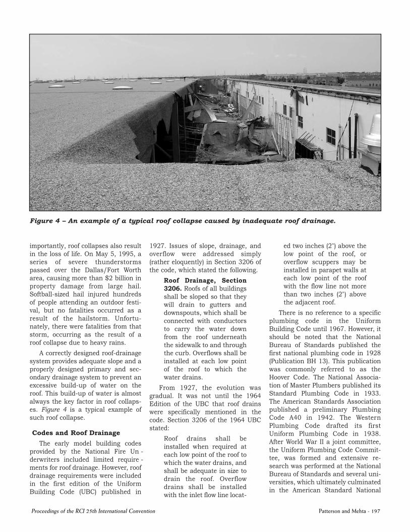
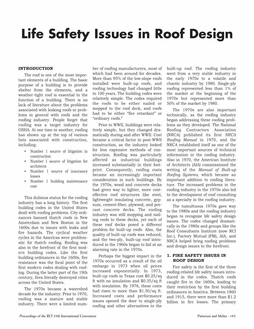
Figure 4 – An example of a typical roof collapse caused by inadequate roof drainage.
importantly, roof collapses also result in the loss of life. On May 5, 1995, a series of severe thunderstorms passed over the Dallas/Fort Worth area, causing more than $2 billion in property damage from large hail. Softballsized hail injured hundreds of people attending an outdoor festival, but no fatalities occurred as a result of the hailstorm. Unfortunately, there were fatalities from that storm, occurring as the result of a roof collapse due to heavy rains.
A correctly designed roofdrainage system provides adequate slope and a properly designed primary and secondary drainage system to prevent an excessive buildup of water on the roof. This buildup of water is almost always the key factor in roof collapses. Figure 4 is a typical example of such roof collapse.
Codes and Roof Drainage
The early model building codes provided by the National Fire Un derwriters included limited re quire ments for roof drainage. How ever, roof drainage requirements were included in the first edition of the Uniform Building Code (UBC) published in
1927. Issues of slope, drainage, and overflow were addressed simply (rather eloquently) in Section 3206 of the code, which stated the following.
Roof Drainage, Section 3206. Roofs of all buildings shall be sloped so that they will drain to gutters and downspouts, which shall be connected with conductors to carry the water down from the roof underneath the sidewalk to and through the curb. Overflows shall be installed at each low point of the roof to which the water drains.
From 1927, the evolution was gradual. It was not until the 1964 Edition of the UBC that roof drains were specifically mentioned in the code. Section 3206 of the 1964 UBC stated:
Roof drains shall be installed when required at each low point of the roof to which the water drains, and shall be adequate in size to drain the roof. Overflow drains shall be installed with the inlet flow line locat
ed two inches (2") above the low point of the roof, or overflow scuppers may be installed in parapet walls at each low point of the roof with the flow line not more than two inches (2") above the adjacent roof.
There is no reference to a specific plumbing code in the Uniform Building Code until 1967. However, it should be noted that the National Bureau of Standards published the first national plumbing code in 1928 (Publication BH 13). This publication was commonly referred to as the Hoover Code. The National Asso cia tion of Master Plumbers published its Standard Plumbing Code in 1933. The American Standards Association published a preliminary Plumbing Code A40 in 1942. The Western Plumbing Code drafted its first Uniform Plumbing Code in 1938. After World War II a joint committee, the Uniform Plumbing Code Com mit tee, was formed and extensive re search was performed at the National Bureau of Standards and several universities, which ultimately culminated in the American Standard National
Proceedings of the RCI 25th International Convention Patterson and Mehta 197

Plumbing Code, ASA A40.81955.
Today’s International Building Code represents the merging of the three national building codes – the BOCA Building Code, the Uniform Building Code, and the Standard Building Code – into one unified building code. The goal was to have a single national building and plumbing code. The International Building Code has been universally accepted for the most part, but there are still three national plumbing codes, which include the Uniform Plumbing Code, the National Standard Plumbing Code, and the International Plumbing Code, each with slightly different philosophies.
Key Drainage Design Issues in the Codes
The key roof design issues addressed in the codes are:
1. Roof slope. 2. Structural issues related to pond
ing, 3. The design of the primary roof
drainage system, and 4. The design of the overflow or sec
ondary drainage systems.
From the beginning, building codes have stated the obvious:
1. Roofs should drain, 2. There needs to be a backup
drainage system in case something happens to the primary drainage system, and
3. Roof structures should be designed to support all the anticipated loads so they do not collapse.
These are pretty simple concepts, but it is alarming how many roof drainage problems persist and how many roofs collapse every year.
Roof Slope
The need for sloping roofs is obvious. Roofs that drain well last longer than roofs that do not drain well, and roofs that do not accumulate water are not likely to collapse. Clearly, however, there are still misunderstandings regarding the issues relat
ed to roof slope. In 1927, the UBC stated, “Roofs of all buildings shall be sloped so that they will drain.” How could it be any clearer? The NRCA published its first Manual of Roof Practice and stated: “enough slope should be builtin so that water does not collect in the low areas between the roofframing members…” Unfortunately, the NRCA finished the sentence with “… so that the roof is completely dry 48 hours after it stops raining.” Water standing for 48 hours does not constitute good drainage, but this 48hour standard found its way into the roofing literature and became part of the first International Building Code in 2000. The 2009 International Building Code defines positive drainage as:
The drainage condition in which consideration has been made for all loading deflections of the roof deck, and the additional slope has been provided to ensure drainage of the roof with 48 hours of precipitation.
The Code further requires lowslope roofs to slope a minimum of ¼ in/ft except for coaltar pitch builtup roofs, which can be sloped 1/8 in/ft It is important, however, to understand that there can be serious problems with roofs with a slope of less than ¼ in/ft. These issues are addressed in the structural requirements in the codes for ponding instability.
Structural Issues Related to Ponding
Roof slope is not only important for roof performance, but roof slope is extremely important in the structural design of a roof. Roof structures with slopes less than 1/4:12 must be evaluated for ponding instability. The concept of ponding instability is not new. The requirement to specifically design roofs for ponding water first appeared in the Uniform Building Code in 1967 in Section 2305(f).
2305(f) Water Accu mu la tion. All roofs shall be
designed with sufficient slope or camber to assure adequate drainage after the longtime deflection from dead load or shall be designed to support maximum loads including possible ponding of water due to deflection. See Section 2307 for deflection criteria.
Ponding instability is critical in roof drainage design, because one of the typical factors in many roof collapses involves the failure of the structure due to progressive deflection under water loads. As water builds up on a roof, the roof structure deflects, and if the slope is inadequate to permit free drainage, the accumulation of water will result. Water continues to build up deeper and deeper as the structure deflects. This progressive buildup of water is one of the key factors in many collapses. Below is the section from the 2009 IBC dealing with ponding instability.
1622.2 Ponding instability. For roofs with a slope less than ¼ inch per foot [1.19 degrees (0.0208 rad)], the design calculations shall include verification of adequate stiffness to preclude progressive deflection in accordance with Section 8.4 of ASCE 7.
Water weighs 62.4 pounds per cubic ft (pcf), and therefore, each inch of water weighs approximately 5.2 pounds per sq ft (psf). It is precisely this weight of water that provides the load on most roofs that leads to roof collapses. The codes have long provided for live load reductions, which commonly allow the reduction in the live load on joists and other roofframing members to as low a 12 psf (depending on the tributary area of the supporting member), which equals slightly more than a 2in uniform water depth on the roof.
Standard deflection criteria for a roof’s structural elements allows for a deflection equal to (span/240), which
Patterson and Mehta 198 Proceedings of the RCI 25th International Convention

is two inches of deflection for a 40ft span. Sloping a roof ¼ in/ft should be considered the very minimum because of variations in construction tolerances. Figure 5 shows a roof that slopes 1/8 in/ft over a span of 40 ft. With a deflection of two inches, the center of the roof’s span is only ½ in above the lowest end (drainage point) of the roof. A deviation of ½ inch in construction tolerances is commonplace, which implies that a part of the roof – from midspan to the eave – has no slope (2½ inches in deflection and 2½ inches in fall).
Any additional deflection (resulting from greater construction tolerances and/or ponding instability) can result in a serious problem – even a collapse. Figure 5 also shows that a roof with the 1¼ in/ft slope has a net slope of 1/8 in/ft (after full deflection) from midspan to the eave, which eliminates any potential ponding. This is an important reason for having a minimum slope of ¼ in/ft. The International Building Code, which allows roof slopes to be reduced to 1/8 in/ft for coaltar pitch, ignores the importance of positive drainage. The Code, however, does require that if the slope is less than ¼ in/ft, the roof should be investigated for ponding instability.
Figure 6 (adopted from Roof Drainage, Ref. 2) shows the importance of slope and the increase in depth of water accumulation with decreasing slope. Decreasing the slope from ¼:12 to 1/8:12 doubles the amount of water on the roof. In other words, the lack of adequate slope can result in catastrophic consequences unless the structure is designed for these loads.
The building codes have taken a step backward in their requirements relating to slope, particularly as it relates to reroofing. The 1988 Uniform Building Code (UBC) addressed the issues related to roof slope and reroofing better than any other code before or after. Presented below is an excerpt from Chapter 32 in the Appendix to the 1988 UBC.
Figure 5 – A roof slope of 1/8 in/ft provides virtually zero net slope after the roof deck assumes its allowable deflection under rain load. A ¼ in/ft roof slope, on the other hand, leaves a net slope of 1/8 in/ft under the same condition.
Figure 6 – For the same head of water over a drainage element (scupper or roof drain), rain load on the roof increases with decreasing roof slope.
Inspections
Sec. 3210. New roof coverings shall not be applied without first obtaining an inspection by the building official and written approval from the building official. A final inspection and approval shall be obtained from the building
official when the reroofing is complete. The preroofing inspection shall pay special attention to evidence of accumulation of water. Where extensive ponding of water is apparent, an analysis of the roof structure for compliance with Section 3207 shall be made and corrective measures, such
Proceedings of the RCI 25th International Convention Patterson and Mehta 199

as relocation of roof drains or scuppers, resloping of the roof or structural changes, shall be made.
An inspection covering the abovelisted topics prepared by a special inspector may be accepted in lieu of the preinspection by the building official.
Further, the 1988 UBC required that the new roof meet the requirements of Chapter 32 of the Code, which required the roof to have a minimum slope of ¼:12. Essentially, the roof had to be inspected, and if there were drainage problems, the roof structure had to be analyzed and the drainage corrected.
It is a mistake to assume that because a building has been around for a long time that the drainage system is adequate. One of the first collapses investigated by the author’s firm involved a 50yearold building that never had a drainage problem— that is until someone tossed a Sunday newspaper up on the roof. That Sunday paper was the perfect size to block the scupper drains on the building, and unfortunately for the owner of the building, the roof was not provided with any overflow drainage system.
Slope is one of the three critical elements of roof drainage design. It is essential that the roof has adequate slope to drain the roof without accumulating excessive amount of water.
The following section deals with the concept of overflow design in order to prevent excessive water buildup.
Overflow Drainage System— Controlling Water Depth on Roofs
Probably the most important element of roof drainage design is controlling the depth of water that can accumulate on the roof. Controlling this depth is a function of the overflow drainage system, also known as the secondary drainage system. Overflow scuppers are prominently mentioned in the 1929 Standard Practice in Sheet Metal Work, which is the forerunner to the Architectural Sheet Metal Manual published by the Sheet Metal and Air Conditioning Contractors National Association (SMACNA). Also, overflow was one of the requirements in the first Uniform Building Code. Why, then, is it that so many existing buildings have no overflow drainage system?
Investigation of a number of roof collapses has revealed that the collapses were either due to the absence or inadequacy of the overflow drainage system. At some point, it is likely that a roof drain will be blocked. It may take 50 years before someone throws a Sunday newspaper on the roof or there is a severe hailstorm, or blowing debris from a hurricane occurs that is severe enough to block the drains. At some point, the primary drainage system will likely become blocked. Water flowing to the drains will carry debris and deposit it at the
low point of the roof, which is where the primary drains are located. Some drains are more likely to become blocked than others. Drainage scuppers are more susceptible to blockage than roof drains. Figure 7 (adopted from Roof Drainage, Ref. 2) shows that a roof drain with a proper strainer can still function, even with debris accumulated around the perimeter of the strainer, whereas the scupper is virtually blocked by the same debris.
The American Society of Civil Engineers recognized the importance of blocked drains and provided the following recommendations for structural engineers in the first ASCE Standard, entitled ANSI/ASCE 788, Minimum Design Loads for Buildings and Structures, which replaced ANSI A58.11982.
8.2 Blocked Drains. Each portion of a roof shall be designed to sustain the load of all rainwater that could accumulate on it if the primary drainage system for that portion is blocked. Ponding instability shall be considered in this situation. If the overflow drainage provisions contain drain lines, such lines shall be independent of any primary drain lines.
Overflow Drainage Requirements
There have been revisions of ASCE 7, but the issues related to overflow
Figure 7 – The relative performance of roof drains and scuppers.
Patterson and Mehta 200 Proceedings of the RCI 25th International Convention

have remained virtually unchanged in ASCE 7 since its inception in 1988, and also in the International Building Code, since its inception in 2000. The structural engineer must assume that the primary drains are blocked, calculate the depth of water that could accumulate on the roof, and design the structure to support those loads. Again, these are pretty simple, commonsense concepts that have been universally accepted in current design standards.
However, there are variations in overflow drainage design theory. Historically, most primary and secondary roof drainage systems were designed based upon the maximum onehour duration, 100year rainfall rate. This is the maximum amount of rain that is likely to occur in one hour, once every 100 years. However, in 1991, the Standard Building and Plumbing Codes changed the requirements for overflow design. The 1991 Standard Plumbing Code adopted the 15minute rainfall rate for the design of overflow drainage systems, which is the maximum rainfall rate expected in 15 minutes once every 100 years. To put it in perspective, the 15minute, 100year rainfall rate is approximately twice the onehour, 100year rainfall rate.
1507.3 Maximum Rainfall Rate for Secondary Drains. Secondary (emergency) roof drain systems or scuppers shall be sized based on the flow rate caused by the 100year, 15minute precipitation as indicated on Figure 1507.3. The flow through the primary system shall not be considered when sizing the secondary roof drain system.
The National Standard Plumbing Code has also adopted this criterion. The rationale for using the 15minute, 100year rainfall rate is based on the concept that roof drains may become blocked during extreme storms like hailstorms and hurricanes. The
Standard Plumbing Code was formerly the Southern Building Code, which was adopted primarily throughout the Southeastern region of the United States, including the hurricaneprone Gulf and Atlantic Coast states. Blowing debris during hurricanes commonly blocks roof drains, and hurricanes often produce extraordinary rainfall. The combination of blowing debris and extraordinary rainfall can be catastrophic for roof drainage systems. The first International Plumbing Code (1997) also adopted this 15minute, 100year rainfall rate, but reverted to using the onehour, 100year rainfall rate for overflow systems in 2000.
Also gone is the old Uniform Building Code standard of using overflow scuppers three times the area of the roof drains. The Uniform Building Code first provided the overflow scupper option in the 1967 Edition, which is shown below.
(c) Overflow Drains and Scuppers. Where roof drains are required, overflow drains having the same size as the roof drains shall be installed with the inlet flow line located two inches (2") above the low point of the roof, or overflow scuppers having three times the size of the roof drains may be installed in adjacent parapet walls with the inlet flow line located two inches (2") above the low point of the adjacent roof and having a minimum opening height of four inches (4").
Overflow drains shall be connected to drain lines independent from the roof drains.
There is a major flaw in this drainage design criterion. This criterion does not take into account the depth of water that develops at the scupper based upon the geometry of the scupper. The fundamental function of the scupper is to control the depth of water, so as to limit the load
on the roof structure and prevent a collapse. The geometry of a scupper is critical. For example, a 6in roof drain has an opening of approximately 28 sq in. Using the old Uniform Building Code’s standard of providing an overflow scupper three times the area of the roof drain, the overflow scupper size would be 84 sq in. The problem with this standard was that a designer could select an 8in wide by 10.5in high scupper and meet the code requirements. However, the head of water at the scupper would have to be 8.4 in to achieve the required flow rate. The net result would be a 10.4in water depth at the scupper (8.4 in of head plus 2.0 in for the scupper inlet elevation). This depth of water could easily cause a collapse in most circumstances. Based upon the old UBC, it was possible to collapse a roof using overflow scuppers three times the area of the roof drains. Roof drains are roughly three times more efficient than scuppers in terms of flow rate. The 8.0in wide by 10.5in high scupper has the flow capacity of almost 790 gallons per minute (gpm). The scupper has about three times the area of a 6in drain. Unfortunately, the head of water required to achieve the 790 gpm of flow through the scupper is 8.4 in, while the head of water required to achieve approximately the same flow is only about 4.0 in.
In 1991, the Standard Plumbing Code introduced a method to determine the depth of water that could accumulate on the roof and required the structural engineer to design the structure based upon this depth of water, assuming the blockage of primary drains. This is the basis of design requirement provided in the 1998 edition of ASCE 7 and the 2000 edition of the International Building Code. This is the most logical approach and simply reinforces the concept that the structural engineer should design the structure for the rain loads expected to occur on a roof.
ASCE/SEI 705 provides a basis for calculating the head of water over roof drains and scuppers. There are also methods for calculating the head
Proceedings of the RCI 25th International Convention Patterson and Mehta 201
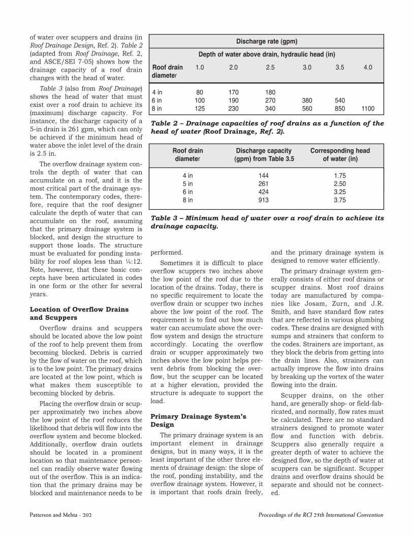
of water over scuppers and drains (in Roof Drainage Design, Ref. 2). Table 2 (adapted from Roof Drainage, Ref. 2, and ASCE/SEI 705) shows how the drainage capacity of a roof drain changes with the head of water.
Table 3 (also from Roof Drainage) shows the head of water that must exist over a roof drain to achieve its (maximum) discharge capacity. For instance, the discharge capacity of a 5in drain is 261 gpm, which can only be achieved if the minimum head of water above the inlet level of the drain is 2.5 in.
The overflow drainage system controls the depth of water that can accumulate on a roof, and it is the most critical part of the drainage system. The contemporary codes, therefore, require that the roof designer
Discharge rate (gpm)
Roof drain diameter
Depth of water above drain, hydraulic head (in)
1.0 2.0 2.5 3.0 3.5 4.0
4 in 6 in 8 in
80 170 180 100 190 270 380 540 125 230 340 560 850 1100
Table 2 – Drainage capacities of roof drains as a function of the head of water (Roof Drainage, Ref. 2).
Roof drain Discharge capacity Corresponding head diameter (gpm) from Table 3.5 of water (in)
4 in 144 1.75 5 in 261 2.50 6 in 424 3.25 8 in 913 3.75
calculate the depth of water that can accumulate on the roof, assuming that the primary drainage system is blocked, and design the structure to support those loads. The structure must be evaluated for ponding instability for roof slopes less than ¼:12. Note, however, that these basic concepts have been articulated in codes in one form or the other for several years.
Location of Overflow Drains and Scuppers
Overflow drains and scuppers should be located above the low point of the roof to help prevent them from becoming blocked. Debris is carried by the flow of water on the roof, which is to the low point. The primary drains are located at the low point, which is what makes them susceptible to becoming blocked by debris.
Placing the overflow drain or scupper approximately two inches above the low point of the roof reduces the likelihood that debris will flow into the overflow system and become blocked. Additionally, overflow drain outlets should be located in a prominent location so that maintenance personnel can readily observe water flowing out of the overflow. This is an indication that the primary drains may be blocked and maintenance needs to be
Table 3 – Minimum head of water over a roof drain to achieve its drainage capacity.
performed.
Sometimes it is difficult to place overflow scuppers two inches above the low point of the roof due to the location of the drains. Today, there is no specific requirement to locate the overflow drain or scupper two inches above the low point of the roof. The requirement is to find out how much water can accumulate above the overflow system and design the structure accordingly. Locating the overflow drain or scupper approximately two inches above the low point helps prevent debris from blocking the overflow, but the scupper can be located at a higher elevation, provided the structure is adequate to support the load.
Primary Drainage System’s Design
The primary drainage system is an important element in drainage designs, but in many ways, it is the least important of the other three elements of drainage design: the slope of the roof, ponding instability, and the overflow drainage system. However, it is important that roofs drain freely,
and the primary drainage system is designed to remove water efficiently.
The primary drainage system generally consists of either roof drains or scupper drains. Most roof drains today are manufactured by companies like Josam, Zurn, and J.R. Smith, and have standard flow rates that are reflected in various plumbing codes. These drains are designed with sumps and strainers that conform to the codes. Strainers are important, as they block the debris from getting into the drain lines. Also, strainers can actually improve the flow into drains by breaking up the vortex of the water flowing into the drain.
Scupper drains, on the other hand, are generally shop or fieldfabricated, and normally, flow rates must be calculated. There are no standard strainers designed to promote water flow and function with debris. Scuppers also generally require a greater depth of water to achieve the designed flow, so the depth of water at scuppers can be significant. Scupper drains and overflow drains should be separate and should not be connected.
Patterson and Mehta 202 Proceedings of the RCI 25th International Convention

Table 3.5 – Size of vertical conductors as per the National Standard Plumbing Code and the Uniform Plumbing Code
Pipe diameter Design flow Maximum drainable (projected) roof area (sq ft) (in) (gpm)
Rainfall intensity (in/h) 1 2 3 4 5 6
2 23 2,176 1,088 725 544 435 363 3 67 6,440 3,220 2,147 1,610 1,288 1,073 4 144 13,840 6,920 4,613 3,460 2,768 2,307
5 261 25,120 12,560 8,373 6,280 5,024 4,187 6 424 40,800 20,400 13,600 10,200 8,160 6,800 7 913 88,000 44,000 29,333 22,000 17,600 14,667
Adapted from the National Standard Plumbing Code, 2003, and Uniform Plumbing Code, 2003, with permission. This table is the same as Table 2.1(a).
Table 3.6 – Size of vertical conductors as per the International Plumbing Code
Pipe diameter Maximum drainable (projected) roof area (sq ft) (in)
Rainfall intensity (in/h) 1 2 3 4 5 6 7 8 9
2 2,880 1,440 960 725 575 480 410 360 320 3 8,800 4,400 2,930 2,147 1,760 1,470 1,260 1,100 980 4 18,400 9,200 6,130 4,613 3,680 3,070 2,630 2,300 2,045
5 34,600 17,300 11,530 8,373 6,920 5,765 4,945 4,325 3,845 6 54,000 27,000 17,995 13,600 10,800 9,000 7,715 6,750 6,000 7 116,000 58,000 38,660 29,333 23,200 19,315 16,570 14,500 12,890
Copyright 2003, International Plumbing Code, Falls Church, Virginia: International Code Council, Inc., reproduced with permission. All rights reserved. This table is the same as Table 2.1(b).
Table 4 – Drainage capacities of roof drains as provided in the three plumbing codes.
Drainage Capacities for Roof Drains
The various plumbing codes generally agree on the design criteria in principle. However, there are variations in the drainage capacities of roof drains between the International Plumbing Code and the other two plumbing codes—the National Standard Plumbing Code and the Uniform Plumbing Code. Table 4 (adopted from Roof Drainage, Ref. 2) shows these variations.
The National Standard and Uniform Plumbing Codes are more conservative. All these flow rates are based upon Manning’s equations, but there are slightly different assumptions regarding the amount of open area in the pipe, which results in the differences in the charts. Roof drain
manufacturers also publish drainage design literature, and most of these manufacturers use the same drainage design assumptions as the International Plumbing Code’s standards.
Scuppers as Drainage Elements and Their Drainage Rates
There are no design provisions for scuppers in the International Build ing Code or the International Plumb ing Code, so scupper drains fall into the category of “Alternate Methods of Construction.” Section 105 of the 2009 International Plumbing Code provides the requirements for “Alternate Methods of Construction,” and these requirements specifically state (Sections 105.4.1 through 105.4.6):
1. The alternate design shall conform to the intent of the provisions of the code.
2. The registered design professional must indicate on the plumbing permit application that the system is an alternative engineered system.
3. The registered design professional shall submit technical data to substantiate the proposed alternative design.
4. The registered design professional shall submit two sets of signed and sealed construction documents for the alternative design.
Proceedings of the RCI 25th International Convention Patterson and Mehta 203

Head of Discharge capacity of scupper, Q (gpm) water, H, in scupper (in) Length of scupper, L (in)
6 8 10 12 18 24 30 36 42
0.5* 6.3 8.4 10.5 12.6 19.0 25.3 31.7 38.2 44.5 1.0 17.4 23.4 29.4 35.4 53.4 71.4 89.4 107.4 125.4 1.5 31.4 42.4 53.5 64.5 97.6 130.6 163.7 196.8 229.8 2.0 47.5 64.5 81.5 98.4 149.3 200.3 251.2 302.0 353.0
2.5 65.2 88.9 112.7 136.4 207.5 278.7 349.8 421.0 492.1 3.0 84.2 115.4 146.5 177.7 271.2 364.8 458.3 551.8 645.4 3.5 102.7 141.4 180.2 218.9 335.2 451.4 575.6 683.9 800.1 4.0 124.8 172.8 220.8 2688 412.8 556.8 700.8 844.8 988.8
Table 2.3 – Drainage Capacity of a Rectangular Scupper (gpm)
Note: the accuracy of discharge capacity values for 0.5 inch head Note: Scupper length, L, below this (stepped) line is less than four times
of water may not be accurate due to the effect of surface tension. the head, 4H. These scupper dimensions should be avoided.
Table 5 – Drainage capacities of rectangular scuppers relative to the head of water.
Of course, there are design data for scuppers, but there are also variations in the formulas used for calculating the flow through a scupper. It is important to understand that water has to build up to a relatively significant depth on the roof to achieve the design flow rate though the scupper. The depth of water that develops is primarily an issue of the width of the scupper. The wider the scupper, the lower the head of water that will develop at the scupper, which is desirable even if the structure is designed to support the loads from a large head of water.
The flow rate of water through scuppers is generally determined by the derivation of an equation known as the Francis Formula, which is Q = 3.33LH1.5, where Q is the flow rate, L is the length of the weir (scupper), and H is the head of water. Because experiments have shown there is a contraction in the water flowing through the weir, the equation has been modified to adjust for this reduction. The modified form is Q = 3.33(L0.2H)H1.5. Table 5 (from Roof Drainage, Ref. 2) has been derived from this equation.
The design of the primary drainage system is relatively straightforward. There are variations in flow rates of drains and scuppers, and further research into these variables would
be helpful in establishing consistent design guidelines.
Drainage Design Requirements for Roof Replacements
The 1967 Uniform Building Code added Chapter 32 to the Appendix of the code, which was titled ReRoofing, and the first section (3209) in that chapter stated that all rroofing had to comply with Section 32 in the Building Code. This was a significant change in the code. However, the most significant change came in 1988 with the addition of the statement that roof systems shall be sloped a minimum ¼ in/ft for drainage. This requirement to provide a minimum slope in Chapter 32 of the 1988 UBC, in combination with the changes made to Chapter 32 in the Appendix for Reroofing, had enormous implications for reroofing design. Chapter 32 in the Appendix required a reroof to conform to Chapter 32 of the Code, which required the roof to be sloped a minimum ¼ in/ft.
There was no reference to draining within 48 hours or allowing 1/8 in/ft for coaltar pitch. From a fundamental design perspective, this was the most appropriate code dealing with roof drainage and roof slope. A minimum slope of ¼ in/ft has long been recognized as the most appropriate minimum slope for good drainage. A
minimum ¼ in/ft is also important from a structural design perspective, as any roof with less than this slope has to be designed for ponding instability. Deflections in structural elements with less than ¼ in/ft slope can result in a progressive collapse due to deflection. In other words, the roof deflects, allowing more water to accumulate until the roof collapses. Clearly, the authors of the 1988 UBC were addressing the issues that cause roof collapses. These changes in the 1988 UBC were met with less than an enthusiastic response from elements of the roofing community. A great number of existing buildings did not have a minimum ¼ in/ft slope. In some cases, it was not only impractical, but it was virtually impossible to provide the minimum ¼ in/ft slope. Then there were the issues from the coaltar pitch industry, where a ¼ in/ft slope could be too much slope for the system. The result of these issues and others was a lessening of the requirements.
Current Drainage Design Standards
Today’s International Building Code is relatively ambiguous regarding positive drainage. As defined, positive drainage is based upon ensuring drainage within 48 hours of precipitation. As previously stated, water
Patterson and Mehta 204 Proceedings of the RCI 25th International Convention

standing for 48 hours does not constitute good drainage. What does 48 hours from precipitation mean? Does it mean 48 hours in summertime conditions or wintertime conditions? A properly sloped roof should drain freely. Other than anomalies in the roof created around penetrations or crickets and valleys, there should be no water ponding after a rain.
The code requires reroofs to have positive drainage, but since the definition is ambiguous and enforcement is difficult. Some building officials have ruled that the design professional is responsible for making the determination of what constitutes positive drainage, but often there is no design professional in the case of reroofing. Certainly, positive drainage is a benefit in terms of roofing longevity and performance, and providing ¼ in/ft eliminates many structural concerns. In those cases where achieving ¼ in/ft is not practical, care should be taken to help limit the amount of water that can accumulate on the roof, and involving a structural engineer should be considered.
It is important to understand that simply resloping a roof with tapered insulation may not be adequate. It is imperative that the drainage system function properly after the tapered insulation is installed. Often, increases in insulation thickness can restrict drains and overflow systems.
One of the most important re quire ments for reroofing is to make sure there is a proper overflow system. This is a code requirement that is often overlooked by many in the roofing industry, but the overflow system is critical in terms of limiting the amount of water that can accumulate on a roof and in preventing roof collapses. As a rule of thumb, some try to limit the depth of water to a maximum of four inches, which prevents the load from water buildup from exceeding the minimum 20 psf live load used throughout much of the southern regions of the country. It is also important to understand that even though there is a minimum 20 psf liveload requirement in the code, there are liveload reductions that are
allowed by code that can reduce live loads on certain structural elements to as low as 12 psf.
FINAL COMMENTS ON DRAINAGE DESIGN
The basic concepts of proper roof drainage design have been around for many years, and there are extensive data and design guides available. The Roof Drainage monograph (Ref. 2) published by the RCI Foundation, provides a much more complete discussion of roof drainage, and every roof consultant should have a copy in his or her library. There are still issues that need clarification and additional research is needed, particularly in the area of water accumulation on roofs and the appropriate flow rates of drains and scuppers.
The roof consultant can play an important role in preventing roof collapses. It is essential that there is a properly functioning overflow system on a building. Checking roofs for an appropriate overflow system and recommending corrective action to add or enlarge overflow drains and/or scuppers should be a standard part of the roof investigation process. Further, improving the drainage and the design and installation of overflow systems should be part of a reroofing project where these systems are inadequate.
LIFE SAFETY ISSUES IN WIND UPLIFT DESIGN OF A ROOF
Few catastrophes are as dramatic as a major roof collapse or 17,000 buildings burning to the ground. However, wind damage to roofs and buildings can be just as dramatic when tornados or hurricanes make a direct strike on a major city. An F5 tornado made a direct hit on the city of Lubbock, Texas, on May 11, 1970, and once again, the 1970s proved to be a pivotal time for roofing design. The Great Plains Life Building, a 20story office building in downtown Lubbock, was in the direct path of the F5 tornado. The building sustained major damage (Ref. Wikipedia). The faculty members in the College of Engineering in Texas Tech University,
Lubbock evaluated the damaged building and found it restorable. The building remained vacant in damaged condition until 1975, when it was restored and renamed the Metro Tower.
Most of the building’s structure was sound, despite major damage caused to some areas that were stressed beyond their elastic limit and were permanently deformed. The permanent deformations in the structure provided an opportunity for Texas Tech engineering faculty to determine the loads required to cause them, allowing them to indirectly calculate the wind loads imposed by the tornado. The 1970 Lubbock tornado provided one of the first opportunities to study the pressures associated with a major tornado. Normally, F5 tornadoes completely destroy what they hit, so there is little left to evaluate. This time, the tornado hit a highrise building. This tornado and the subsequent evaluations of the damages associated with this tornado were significant to the understanding of wind pressures, moving Texas Tech University to the forefront of research related to wind pressures on buildings.
Wind uplift issues on roofs were not something that was dealt with in the early codes. Most roofs were mopped or nailed to wood or concrete structures, and wind was not much of an issue on that type of construction. The methods of attaching roofs to buildings became a major issue after the 1953 General Motors fire in Livonia, Michigan. The method of adhering the insulation to the steel deck on the Livonia GM plant had contributed to a massive fire loss. Studies by both UL and FM showed that the bitumen used to attach the roof could contribute significantly to a fire that developed on the inside of a building. Construction standards for adhering insulation to steel decks changed. The new standards required that the adhesives used to adhere insulation to a steel deck had to be tested and approved and that the application of the adhesive must be limited to the top rib of the steel deck.
Proceedings of the RCI 25th International Convention Patterson and Mehta 205

Insulation was still adhered to steel decks until the 1980s.
In 1983, FM reported (FM 12883) that just over 30% of the wind losses between 1971 and 1980 involved losses to steel decks, and in losses where the insulation lifted off the deck, there were inadequate adhesives, particularly at the edge and perimeter. Further, FM’s investigations indicated that mechanically attached insulation fared far better than adhered insulation. FM stopped approving the installation of insulation to steel decks using adhesives and only approved mechanically attached in sulation. This standard was adopted industrywide by the mid to late 1980s. FM also recognized that wind losses were particularly problematic at the perimeter and in the corners. In 1983, FM required that the fasteners be increased by 50% in the corners of FM 160 systems and increased by 50% in the both the corners and the perimeter of the FM 190 systems.
Factory Mutual provided the first sophisticated roof design guidelines for wind uplift pressures. These design guidelines included charts to determine the appropriate wind uplift pressures on roofs for various exposures and heights. In addition, FM provided lists of roofing systems that had been tested to meet those wind uplift pressures. FM has long been at the forefront of roof design issues and by the 1980s had become the de facto design standard for wind uplift on roofs. Factory Mu tual tested more lowslope roofing systems for wind uplift than any other agency and provided so phisticated de sign standards for wind uplift on roofs. The codes ad dressed wind uplift, but there was little guid
ance for roof design. Most roofs were de signed using FM standards.
The national codes and FM used the fastest mile wind speeds until 2000, when the first IBC was published. However, seven years earlier, the American Society of Engineers (ASCE) changed from using fastest mile wind speed to using threesecond gust wind speeds (ASCE 793 Minimum Design Loads for Buildings and Other Structures). The 2000 International Building Code adopted the ASCE standards. In 2000, there was a divergence between the code requirements and Factory Mutual. ASCE 793 was the most current and accurate design standard of the day, but the use of the ASCE 7 design standards was slow to take hold in the roofing design community. How ever, by the year 2000, ASCE 7 was clearly the design standard for wind uplift. Even so, many (perhaps most) in the roofing design community continued to use the FM design standards.
Fundamentals of Wind Uplift Design
The standard wind speeds used for wind uplift design are based upon the threesecond gust wind speed with a 50year recurrence interval. These wind speeds are based upon measurements taken at 33 ft above the ground in an area with relatively open terrain and are provided as wind
speed contours superimposed on the map of the United States. The pressure related to wind speed is referred to as the velocity pressure (q) and is obtained from Bernoulli’s Equation. The velocity pressure for a wind speed of 100 mph would be 25.6 psf. It is important to realize that the velocity pressure is a function of the square of the wind velocity, so a 50mph wind would only have a velocity pressure of 6.4 psf, or one fourth of the pressure at 100 mph. With respect to wind pressure, Bernoulli’s Equation is generally stated as:
q = 0.00256 V2,
where q = velocity pressure in lbs per sq ft (psf) and V is the wind speed in miles per hour (mph).
Bernoulli’s Equation is the basis for determining wind uplift pressure on roofs, but it is only the first step. There are a variety of other factors that must be taken into consideration when calculating the wind uplift pressure on roofs. It is helpful to understand how wind pressures develop on roofs. The wind uplift pressure occurs as a result of differences in pressure. The atmospheric pressure is lowered when wind blows across the roof. This is the Bernoulli Effect, and this effect allows airplanes to fly. As an airplane picks up velocity, the air pressure on the top of the wing is lowered, resulting in lift. The same thing happens on a roof. Wind lowers the pressure on
Figure 8 – Uplift pressure on a roof is equal to the difference between the interior air pressure (generally the atmospheric pressure of 2,100 psf) and the exterior air pressure.
Patterson and Mehta 206 Proceedings of the RCI 25th International Convention

Figure 9 – Wind uplift pressure on a mechanically fastened singleply roof on a steel deck.
top of the roof, and the difference between the interior pressure and exterior pressure results in wind uplift pressure. Figure 8 shows a building with no wind, where the air pressure inside and outside are equal (to atmospheric pressure of 2,100 psf) and thus there is no uplift pressure on the roof. This figure also shows a building subjected to wind, which lowers the pressure on top of the roof (to say 2,050 psf), while the interior pressure remains at the atmospheric pressure (of 2,100 psf), resulting in uplift pressure of 50 psf on the roof.
It is also helpful to understand how this difference in wind uplift pressure results in wind uplift on the roof. Wind uplift pressure develops as a result of the difference in pressures between the inside and the outside of the building. The uplift pressure acts on the element that prevents the wind pressure from equalizing. This is generally the roof, which provides an airtight or semiairtight barrier between the inside and outside of the building that we call the critical layer. Figure 9 shows how the wind uplift pressure develops on a mechanically attached roof system.
Bernoulli’s Equation gives us wind pressure and Bernoulli’s Effect explains how wind pressure develops.
The next step is to modify the equation to develop a velocity pressure for a specific building. As stated earlier, wind speed maps are based on threesecond wind gusts measured 33 ft above the ground in relatively open terrain. In order to determine the wind uplift pressure on a roof, the basic velocity pressure for the given wind speed must be modified by certain factors to adjust the pressures based upon the building parameters. These factors include an allowance for ground roughness, because the winds are different, depending upon the roughness of the terrain. The more open the terrain, the higher the wind speed; and conversely, the rougher the terrain, the lower the wind speed. These variations in ground roughness are categorized into Surface Roughness Categories B, C, and D. There was a Surface Roughness A for downtown urban terrain, but this category was eliminated. Also, up to a point, the wind speeds increase with an increase in elevation, so the winds are higher on top of a tall building than on top of a short building. The pressure formula is modified based on the ground roughness and height of the building in order to adjust the wind pressure determined using the standard wind speed maps to the
actual conditions of the building. This modifier is called the Velocity Pressure Exposure Coefficient, Kz. Figure 10 illustrates how the height of the building and the ground roughness affect the wind speed and gives a description of the Ground Roughness Categories.
The final equation includes the Importance Factor (I), the Direc tion ality Factor (Kd), and Topo graphical Factor (Kzt), which further refine the equation. The Importance Factor is like a safety factor that increases or decreases the load, depending upon the importance of the building. The directionality factor reduces the load based on the low probability that the maximum wind speed will occur from the direction that produces the maximum wind pressure. The Topographical Factor increases loads to account for buildings located on elevated topography. The final equation for velocity pressure is:
qz = 0.00256(Kz)(Kzt)(Kd)V2)(I)
This equation gives us the velocity pressure for a specific building. The velocity pressure has now been adjusted for the height of the building, the terrain, the type of building, and the topography. There is one more key issue in developing wind
Proceedings of the RCI 25th International Convention Patterson and Mehta 207

Figure 10 – The effect of ground roughness categories on wind speed, and hence on wind uplift pressure on the roof.
uplift pressure, and that involves ballooning, which occurs as a result of an increase in internal pressure caused by an opening on the windward side. Ballooning typically occurs when a door or window on the windward side of the building blows in, becomes trapped, and increases the interior pressure. The design for wind uplift loads on the roof must be increased in these cases. Figure 11 is an illustration of the ballooning effect where there is an opening on the windward side and no (or extremely small) openings on the other sides to allow the additional pressure to dissipate. Such buildings are referred to as “partially enclosed” buildings by wind standards and codes.
The next step is to convert the velocity pressure to uplift pressure on the roof. This step involves the pressure zones on the roof and the internal and external pressure coefficients. Wind uplift is higher along the perimeter and highest at the corners. Typically, there are three zones:
1. The field of the roof, 2. The perimeter of the roof, and 3. The corner of the roof.
Patterson and Mehta 208
Each zone has a different wind uplift pressure, and there is a different External Pressure Coefficient (GCp) for each zone. Table 6 (designated as Table 8 in Wind Pressures on Low Slope Roofs, Ref. 3) shows typical zones on roofs and the different coefficients used in the equation to develop wind uplift pressure.
As previously discussed, the uplift pressure on the roof is the difference between the internal and external pressures. ASCE gives us the Ex ter nal Pressures Coefficient (CGp) based upon the zone on the roof (field, perimeter, and corner) and the height of the building (above and below 60
Figure 11 – Balooning effect in a partially enclosed building.
Proceedings of the RCI 25th International Convention

Table 6 – External pressure coefficients and wind zones on a lowslope roof.
ft). ASCE also provides the Internal Pressure Coefficient (GCpi), as shown in Table 7 (designated as Table 9 in Wind Pressures on Low Slope Roofs, Ref. 3).
The formula for calculating wind uplift pressure on roofs is shown below with pressure (p) equal to the velocity pressure (qh) times the difference between the Internal Pressure Coefficient (CGp) and External Pressure Coefficient (CGpi).
p = qh [(GCp) – (GCpi)]
For ease of use, these equations have been converted into tabular format that provides winduplift pressure for various wind speeds, height of the roof, and various wind zones (in Wind Pressures on Low Slope Roofs, Ref. 3). Table 8 shows one such table.
Factory Mutual Design Standards
Factory Mutual (FM) has long been a leader in roof design and for many years its ratings have provided the de facto standard for designing roofs to resist wind uplift pressures. The FM design standards for wind uplift are based upon the same concepts described above. In addition, however, FM provided design guidelines that allowed the designer to take the wind
uplift pressures and select a roof assembly that would resist those uplift pressures. One major advantage for FM was the comprehensive testing performed at FM’s laboratories. Roofing manufacturers had to test their roofing assemblies in FM’s laboratories in order to sell their roofing systems to FMinsured clients. As a result, FM developed extensive, unparalleled data on the wind uplift resistance of almost every roofing assembly available.
In addition to the extensive testing, FM developed charts for wind uplift pressure for different building heights, different wind speeds, and different ground roughness coefficients. The roof designer selected the ground roughness coefficient, the
wind speed from the
Table 9 – Values of Internal Pressure Coefficients (GCpi) for a Building of Any Mean Roof Height
Enclosure Classification (GCpi)
Open buildings 0.00 Partially enclosed buildings 0.55 Enclosed buildings 0.18
map, and the wind uplift pressure from the chart. The designer’s next step was to select a roof system designed to resist those pressures from FM’s database.
Historically, there Table 7 – Internal pressure coefficients as a were three pressure function of the enclosure classification of zones and two roof the story below the roof.
Table 8 – Wind uplift pressures on various wind zones of a lowslope roof as a function of roof heights and site exposure.
Proceedings of the RCI 25th International Convention Patterson and Mehta 209

classifications. Zone 1 was for pressures up to 30 psf, and roofs with FM Class 160 were acceptable. Zone 2 was for pressures between 31 and 45 psf, and roofs with FM Class 190 were acceptable. Zone 3 was for pressures above 45 psf, and only monolithic decks like concrete were approved. Roofs tested to meet FM Class 160 were tested for pressures up to 60 psf, and these roofs were acceptable for design wind uplift pressures up to 30 psf. Roofs tested to FM Class 190 were tested to pressures up to 90 psf and were acceptable for wind uplift pressures up to 45 psf. This established the safety factor of two for wind uplift on roof assemblies.
There were additional requirements for the roof systems. FM recognized that the wind uplift pressures were greater along the perimeter and in the corners of the roof, so FM required enhancements in the attachment at the corners and perimeter. In 1983, FM 128 required that fasteners be increased by 50% in the corners for Class 160 roofs and required that fasteners be increased by 50% both at the perimeter and in the corners for Class 190 roofs. However, there appeared to be a disconnect between the actual pressures occurring at the perimeter and corners and the attachment enhancements recommended in FM design standards. The 1983 FM 128 Loss Prevention Data Sheet stated that the uplift pressures for the perimeter could be calculated by multiplying the field pressures by two, and the corner pressures by multiplying the field pressures by three. However, FM only required increasing the fasteners by 50% in the corners for Class 160 roof assemblies and by 50% at the perimeter and in the corners for Class 190 roof assemblies.
This disconnect was somewhat rectified in 1991. FM required that the fasteners be increased by 50% along the perimeter and 100% in the corners for Class 190 roof assemblies, but made no change in the requirements for FM Class 160. FM also recognized an increase in pressure on roofs from ballooning and
required the pressures be increased by 25% for partially enclosed buildings. Otherwise, there were no other significant changes. Roofs were classified as either Class 160 for design uplift pressures up to 30 psf or Class 190 for design wind uplift pressures up to 45 psf. Steel decks were not recommended for pressures over 45 psf. The requirement to increase fasteners by 50% at the perimeter and 100% in the corners for the Class 190 systems more closely represented the increased uplift pressures occurring at the perimeter and in the corners.
FM made substantial changes in 1996. The highest wind uplift rating for roofs was FM Class 190 until 1996, at which time FM went from three zones to five zones and from a maximum of FM Class 190 to a maximum FM Class 1180. FM also increased pressures resulting from ballooning to 50% instead of 25%. Curiously, however, FM lowered the enhancement requirement in the corners from an increase in fasteners of 100% to an increase in fasteners of 75%. This lowering of the enhancement requirement was especially interesting considering FM required basesheet fasteners to be increased by 75% at the perimeter and by 160% in the corners, which was more in line with the actual increases in pressures. Again, there appeared to be a disconnection between the enhancement requirements and the actual uplift loads at the perimeter and corners. ASCE adopted the threesecond gust wind speed as its standard in 1993, but FM maintained the fastest mile wind speed standard until 2002.
There were major changes in the codes and design standards in 2000. The three national building codes were consolidated into the International Building Code (IBC), which was published in 2000. The 2000 IBC adopted ASCE 7 as the standard for wind design, which included using the threesecond gust wind speed. This change also effectively raised the building code wind uplift standards above FM’s standards. Roofing Design and Practice (Ref. 4) was also published in 2000 by
Prentice Hall and recognized the discrepancies between FM’s design standards and the new IBC requirements. FM’s wind uplift pressures were below the IBC requirements and the FM enhancements at the perimeter and corners did not compensate for the increase in wind uplift pressures in these areas. Roofing Design and Practice presented a design standard for wind that included the requirement to design the roof system for the actual wind uplift pressures in the field, perimeter, and corners. This was a significant departure from FM’s design standards and was necessary in order to ensure the wind uplift design met the requirements of the IBC. This departure was also recognized in the 2000 AIA Master Specification in Section 1.4.C Roof System Design, which stated the following:
1.4.C Roof System Design: Provide a roofing system that is identical to systems that have been successfully tested by a qualified testing and inspecting agency to resist uplift pressures calculated according to ASCE 7.
Corner Uplift Pressure: <Insert Number> psf
Perimeter Uplift Pressure: <Insert Number> psf
FieldofRoof Uplift Pres sure: <Insert Num ber> psf
FM again revised FM 128 in 2001. FM retained the fastest mile wind speed, which maintained FM’s uplift pressures well below the ASCE 7 standard and IBC. However, FM eliminated zones and introduced a design standard similar to that included in Roofing Design and Practice and the AIA Master Spec. The new FM design standard was based upon taking the actual wind uplift pressure, multiplying the uplift pressure by two (for a safety factor), and then selecting a roof system that was tested to meet the design winduplift pressure. FM
Patterson and Mehta 210 Proceedings of the RCI 25th International Convention

provided a chart showing the system ratings that were required for the field, perimeter, and corner, which was in line with the actual design requirements based on actual load. If the roof had an uplift pressure of 30 psf, an FM 160 system would be used in the field, an FM 190 system would be used at the perimeter, and an FM 1135 system would be used in the corner. This method provided a roof system that was tested for the uplift pressures in the field, perimeter, and corners. Below is an example of FM’s 2001 chart for selecting an appropriate roof.
Field Perimeter Corner
160 190 1135
190 1105 1165
1105 1150 1225
The new method still used the uplift pressures with the lower wind speeds from the fastest mile wind maps, so the design pressures were below the ASCE and IBC standards. This new method of selecting a roof system based on the actual uplift pressures resolved the design problems associated with perimeters and corners. It should have been obvious that increasing the fastening pattern of an FM Class 160 system by 75% would in no way increase the rating of the roof system to an FM Class 1135. In fact, there were very few roof systems over steel decks that would meet a 1135 system on a steel deck in 2001. Again, FM retained the option to increase the fasteners by 50% at the perimeter and 75% in the corners, even though it appeared to be clear that the enhancement standards were inadequate. In 2002, FM finally adopted the ASCE 798 standard based upon the threesecond gust wind speed, which brought FM design standards in line with ASCE and IBC standards. The differences in uplift pressure using the different wind speeds were significant. Below is an example of a typical distribution center in Houston, Texas.
FM finally amended its standards in 2007 and brought the FM design standards in line with the ASCE 7 standard and IBC. In 2007, FM only
2001 FM Standard Using Fastest Mile 2002 FM Standard Using 3Secong Gusts
Wind Speed: 90 mph Wind Speed: 120 mph Pressure: 34.5 psf Pressure: 54 psf System: FM 175 System: FM 1120
permitted enhancements in the attachment under very restricted circumstances. Enhancements can only be used for buildings in nonhurricaneprone regions (with wind speeds of 90 mph or less) with roof heights below 75 ft where the partially enclosed rating does not exceed 175. The roof height is further limited to 30 ft for buildings located in areas with ground exposure D. The enhancement options were also significantly increased. The perimeter enhancement was maintained at 50% but with the restriction of having at least one fastener per two sq ft, which results in 16 fasteners for a 4 x 8ft insulation board. The corner enhancement was changed to one fastener per sq ft or 32 fasteners for a 4 x 8ft insulation board. These were substantial increases in the previous enhancements of 50% at the perimeter and 75% in the corners.
While Factory Mutual’s data sheets became de facto design standards in roof design, the FM standards technically only applied to FMinsured projects and were not a substitute for designing roofs to meet the building codes or to meet the most current design standards from ASCE 7. Until 2007, the design of roofs using FM design standards likely resulted in roofs that were underdesigned when wind speeds approached the upper limits provided for in the codes. The most vulnerable area of the roof was the corner, where FM inexplicably reduced its requirements for enhancements in 1996 and failed to amend the enhancement requirement until 2007. Certainly, there have been many wind uplift roof failures since 1993, but it is important to note that the vast majority of the roofs designed using FM standards have performed well and have not blown off.
The deficiencies in the FM wind
uplift design criteria are mitigated by several factors. First of all, it is relatively unusual for the wind speeds to reach the maximum design wind speeds. The wind uplift pressure is a function of the square of the velocity, so the uplift pressure associated with an 80mph wind is 64% of the wind pressure from a 100mph wind. Therefore, roofs are rarely exposed to the full uplift pressure. Another mitigating factor is the safety factor of two. Doubling the uplift pressure is a substantial safety factor, especially when the loads are high. The safety factor is 30 psf in an FM Class 160, but the safety factor is 120 psf in an FM Class 1120. Another mitigating factor is the gaps in the FM design zones. In 1996, a roof with an FM design winduplift pressure of 31 psf would fall into an FM Zone 2, requiring an FM Class 190, tested for a winduplift pressure of 90 psf. This effectively increased the safety factor to almost three. Also, roof designers often simply specified an FM Class 190 roof assembly, even when an FM Class 160 was required.
COMBINED IMPACT OF RAIN LOADS AND DOWNWARD WIND PRESSURES
A commonly ignored consideration with respect to the structural design of lowslope roofs is the downward wind pressure on them. Although wind uplift is a major concern with lowslope roofs, the downward pressure cannot be ignored in many situations.
For lowheight roofs in lowwind regions, the downward wind pressure is lower than the roof’s live load. Ignoring it is, therefore, of little or no consequence. However, in several situations (such as in highwind regions and/or tall buildings, the downward wind pressure may be substantially larger than the roof live load, and can
Proceedings of the RCI 25th International Convention Patterson and Mehta 211

cause serious problems when it occurs in combination with high rain load on the roof due to inadequate drainage.
Additionally, during severe storms, the rainfall intensity over a short duration (5, 10, and 15minute durations) is far greater than the standard design intensity of one hour. These intense rainfall intensities also typically occur during conditions of high wind speeds. The combination of downward wind pressure (resulting from high wind speeds) and the additional load occurring as a result of higherthandesigned rainfall can become catastrophic for buildings that are designed to the very minimum standards allowed by the codes. The codes and standards must require architects and engineers to evaluate such a possibility.
CONCLUDING REMARKS
The design of roofs has evolved over the years with changes in our understanding of the roofrelated life safety issues. The evolution in our understanding has resulted in changes in codes and design standards. The National Board of Fire Underwriters (Ref. 4) made major contributions at the beginning of the twentieth century and literally provided the forerunner of the modern building code. UL and FM have made major contributions to roof design for more than 100 years. Codes and standards continued to evolve over the years with the development of the modern building and plumbing codes.
In the 1970s, NRCA published the first NRCA Roofing Manual and the AIA commissioned the Manual of Builtup Roofing, both of which contributed significantly to the body of literature on roofing and roof design. Soon after, the International Roofing and Waterproofing Consultants and the Roof Consultants Institute were established, promulgating ethical standards and laying the foundation for the field of professional roof design. The American Society of Civil Engineers and the Structural Engineering Institute also contributed significantly toward both wind and drainage design, particularly in the 1990s.
Major changes occurred in the decade beginning in 2000. The first International Building Code and International Plumbing Code were published in 2000 and were the consolidation of the three national codes. Roofing Design and Practice (Ref. 4) was published in 2000 and was the first roofing book that specifically addressed roofrelated life safety issues. The RCI Foundation commissioned and published Wind Pressures on Low Slope Roofs (Ref. 3) and Drainage Design (Ref. 2), which were comprehensive design manuals related to wind and drainage design respectively.
There is still significant work to be done in the field of roof design for life safety issues. There is limited data and research related to the buildup of water over drains, which is a critical component related to the determi
nation of water loads on roof. The roofing industry has had a turbulent history but has come a long way. The challenge is to take this information to the rest of the design community, lead the way in research to improve the design standards, and improve our understanding of roof design for future generations.
REFERENCES 1. Harry C. Brearly, The History
of the National Board of Fire Underwriters, Fredrick A. Stokes Company, New York, 1916.
2. Stephen Patterson, Madan Mehta, and Richard Wagner, Roof Drainage, Roof Consultants Institute Foundation Publication No. 02.03.
3. Stephen Patterson and Madan Mehta, Wind Pres sures on LowSlope Roofs, Roof Consultants Institute Foundation Publication No. 01.01 (Revised 2005).
4. Stephen Patterson and Madan Mehta, Roofing Design and Practice, Prentice Hall, 2001.
5. 1915 Building Code recommended by the National Board of Fire Underwriters.
Patterson and Mehta 212 Proceedings of the RCI 25th International Convention