life safety code - mjobee.orgmjobee.org/life safety egress.pdf · lighting levels below 1 ft-candle...
TRANSCRIPT
Life Safety Code Handbook ® 2000 Edition
Copyright © 2000 NFPA
7.8 ILLUMINATION OF MEANS OF EGRESS
When fire occurs in a building, the degree of visibility in corridors, stairs, and passagewaysmight mean the difference between orderly evacuation and chaos and possibly the differencebetween life and death. A brief glance at the history of fires reveals several noteworthy fires inwhich the failure of normal or emergency lighting was a major factor in the casualties incurred.A list of some of these fires follows:
Iroquois Theater, Chicago, 1903 602 deaths20
Cocoanut Grove Night Club,
Boston, 1942 492 deaths21
Baltimore Oyster Roast, 1956 11 deaths22
Apartment house, Boston, 1971 8 deaths23
Summerland, Isle of Man, 1973 50 deaths24
Mental hospital, Mississippi, 1978 15 deaths25
The report on the 1971 Massachusetts apartment fire where eight people died stated: “Among theconditions contributing to the . . . loss of life were . . . the lack of emergency lighting and thelack of illuminated exit signs.”
The report on the 1973 fire in the amusement complex on the Isle of Man in Great Britain, where50 people died, stated, “The problems with the evacuation are . . . (5) an insufficient number ofexit signs and directional signs . . . (7) The emergency lighting did not come on when the mainpower was shut off by a staff member in an act of misguided zeal.”
The report on the 1978 mental hospital fire in Mississippi, where 15 people died, stated:
Heat and flame . . . impinged directly on the emergency lighting conduit, causing . . . a shortcircuit to occur. The short tripped the circuit breaker . . . leaving the north end of the buildingwithout emergency lighting. However, in this fire, the emergency lighting circuits on the firstfloor were not used. The dual-function lighting circuits were switched in the “off” position inboth wards. The attendant entering Ward 1 to evacuate the residents did not turn the lights on. InWard 2, the switch could not be reached by the attendants, and the circuit shorted out soon afterthe discovery of the fire. The darkness contributed to the difficulty in evacuating both wards.26
A lack of illuminated exit signs in several key places was also noted in the report.
7.8.1 General.
7.8.1.1*

Life Safety Code Handbook ® 2000 Edition
Copyright © 2000 NFPA
Illumination of means of egress shall be provided in accordance with Section 7.8 for everybuilding and structure where required in Chapters 11 through 42. For the purposes of thisrequirement, exit access shall include only designated stairs, aisles, corridors, ramps, escalators,and passageways leading to an exit. For the purposes of this requirement, exit discharge shallinclude only designated stairs, aisles, corridors, ramps, escalators, walkways, and exitpassageways leading to a public way.
Illumination of means of egress is not required unless specifically called for in the appropriateoccupancy chapter. However, all occupancy chapters do require illumination, but there are a fewexemptions. For example, in new assembly occupancies, 12.2.8 exempts private-party tents notlarger than 1200 ft2 (111.5 m2) from the illumination requirement. Subsection ___.2.8 (forexample, 36.2.8 for new mercantile occupancies) of each occupancy chapter providesillumination requirements.
A.7.8.1.1
Illumination provided outside the building should be to either a public way or a distance awayfrom the building that is considered safe, whichever is closest to the building being evacuated.
7.8.1.2
Illumination of means of egress shall be continuous during the time that the conditions ofoccupancy require that the means of egress be available for use. Artificial lighting shall beemployed at such locations and for such periods of time as required to maintain the illuminationto the minimum criteria values herein specified.Exception: Automatic, motion sensor-type lighting switches shall be permitted within the meansof egress, provided that the switch controllers are equipped for fail-safe operation, theillumination timers are set for a minimum 15-minute duration, and the motion sensor is activatedby any occupant movement in the area served by the lighting units.
7.8.1.3*
The floors and other walking surfaces within an exit and within the portions of the exit accessand exit discharge designated in 7.8.1.1 shall be illuminated to values of at least 1 ft-candle (10lux) measured at the floor.
A.7.8.1.3
A desirable form of means of egress lighting is by lights recessed in walls about 1 ft (30 cm)above the floor. Such lights are not likely to be obscured by smoke.Exception No. 1: In assembly occupancies, the illumination of the floors of exit access shall beat least 0.2 ft-candle (2 lux) during periods of performances or projections involving directedlight.Exception No. 2*: This requirement shall not apply where operations or processes require lowlighting levels.

Life Safety Code Handbook ® 2000 Edition
Copyright © 2000 NFPA
A.7.8.1.3 Exception No. 2
Some processes, such as manufacturing or handling of photosensitive materials, cannot beperformed in areas provided with the minimum specified lighting levels. The use of spaces withlighting levels below 1 ft-candle (10 lux) might necessitate additional safety measures, such aswritten emergency plans, training of new employees in emergency evacuation procedures, andperiodic fire drills.
The Code requires that there be at least 1 ft-candle (10 lux) of illumination at floor level in allthree elements of a means of egress, that is, the exit access, the exit, and the exit discharge. Forthe purposes of Section 7.8, the Code limits exit access to designated stairs, aisles, corridors,ramps, escalators, and passageways leading to an exit. Such components should include thoseportions of the exit access serving occupied spaces. It is not necessary to keep the lights on in allrooms if the rooms are not occupied. For the purposes of Section 7.8, the Code limits exitdischarge to designated stairs, aisles, corridors, ramps, escalators, walkways, and passagewaysleading to a public way. Designated is meant to be designation by the authority havingjurisdiction. While motion pictures, slides, and the like are being shown in theaters, auditoriums,and other assembly occupancies, Exception No. 1 to 7.8.1.3 permits the level of illumination canbe reduced to 0.2 ft-candle (2 lux).
7.8.1.4*
Required illumination shall be arranged so that the failure of any single lighting unit does notresult in an illumination level of less than 0.2 ft-candle (2 lux) in any designated area.
All lights, circuits, or auxiliary power must be arranged to ensure continuity of egress lighting.This arrangement can be accomplished by means such as use of duplicate light bulbs in fixtures,overlapping light patterns, or overlapping dual circuits.
A.7.8.1.4
An example of the failure of any single lighting unit is the burning out of an electric bulb.
7.8.1.5
The equipment or units installed to meet the requirements of Section 7.10 also shall be permittedto serve the function of illumination of means of egress, provided that all requirements ofSection 7.8 for such illumination are met.
7.8.2 Sources of Illumination.
7.8.2.1*
Illumination of means of egress shall be from a source considered reliable by the authorityhaving jurisdiction.
A.7.8.2.1

Life Safety Code Handbook ® 2000 Edition
Copyright © 2000 NFPA
An example of a power source with reasonably ensured reliability is a public utility electricservice.
7.8.2.2
Battery-operated electric lights and other types of portable lamps or lanterns shall not be used forprimary illumination of means of egress. Battery-operated electric lights shall be permitted to beused as an emergency source to the extent permitted under Section 7.9.
7.9 EMERGENCY LIGHTING
Emergency lighting is not required unless specifically called for in the appropriate occupancychapter. Most occupancy chapters require emergency lighting in medium-to-large buildings.Subsection ___.2.9 (for example, 12.2.9 or 36.2.9 for new assembly and new mercantileoccupancies) of each occupancy chapter provides emergency lighting requirements.
7.9.1 General.
7.9.1.1*
Emergency lighting facilities for means of egress shall be provided in accordance with Section7.9 for the following:(1) Buildings or structures where required in Chapters 11 through 42(2) Underground and windowless structures as addressed in Section 11.7(3) High-rise buildings as required by other sections of this Code(4) Doors equipped with delayed egress locks(5) The stair shaft and vestibule of smokeproof enclosures, which shall be permitted to include
a standby generator that is installed for the smokeproof enclosure mechanical ventilationequipment and used for the stair shaft and vestibule emergency lighting power supply
For the purposes of this requirement, exit access shall include only designated stairs, aisles,corridors, ramps, escalators, and passageways leading to an exit. For the purposes of thisrequirement, exit discharge shall include only designated stairs, ramps, aisles, walkways, andescalators leading to a public way.
A.7.9.1.1
Emergency lighting provided outside the building should be to either a public way or a distanceaway from the building that is considered safe, whichever is closest to the building beingevacuated.
7.9.1.2
Where maintenance of illumination depends on changing from one energy source to another, adelay of not more than 10 seconds shall be permitted.
An on-site generator driven by a prime mover must be automatically started and capable of

Life Safety Code Handbook ® 2000 Edition
Copyright © 2000 NFPA
picking up the emergency lighting load within 10 seconds. Where the generator set is not able tosupply power within this time frame, an auxiliary power source must be provided.
Some turbine-driven emergency generators take longer than 10 seconds to reach operating speed.A backup battery pack, such as an uninterruptible power supply (UPS), capable of deliveringemergency power for a few minutes must be used in conjunction with any on-site generator thatcannot meet the 10-second requirement.
Section 700-5 of NFPA 70, National Electrical Code,27 allows use of an emergency generatorfor load shedding and peak load shaving, provided that these loads can be disconnected whennormal power to the emergency lighting system is lost.
Although not required by NFPA 70, the use of bypass-isolation transfer switches should beconsidered. These devices allow maintenance and repair of the transfer switch mechanismwithout interruption of power to the emergency loads. Bypass switches are interlocked to preventsimultaneous interconnection of the two power sources, and isolation of the transfer switch isusually accomplished by operation of a drawout handle. This type of construction should be usedwhere continuity of electrical service to the emergency system is essential. See Exhibit 7.85.
Exhibit 7.85 Schematic of bypass-isolation transfer switch.
7.9.2 Performance of System.
7.9.2.1*
Emergency illumination shall be provided for not less than 11/2 hours in the event of failure ofnormal lighting. Emergency lighting facilities shall be arranged to provide initial illuminationthat is not less than an average of 1 ft-candle (10 lux) and, at any point, not less than 0.1ft-candle (1 lux), measured along the path of egress at floor level. Illumination levels shall be

Life Safety Code Handbook ® 2000 Edition
Copyright © 2000 NFPA
permitted to decline to not less than an average of 0.6 ft-candle (6 lux) and, at any point, not lessthan 0.06 ft-candle (0.6 lux) at the end of the 11/2 hours. A maximum-to-minimum illuminationuniformity ratio of 40 to 1 shall not be exceeded.
A.7.9.2.1
The illumination uniformity ratio is determined by the following formula:
The Code requires a 1-ft-candle (10-lux) average and establishes a 0.1-ft-candle (1-lux)minimum, with a uniformity ratio maximum of 40 to 1 to prevent excessively bright and darkspots.
7.9.2.2*
The emergency lighting system shall be arranged to provide the required illuminationautomatically in the event of any of the following: (1) Interruption of normal lighting such as any failure of a public utility or other outside
electrical power supply(2) Opening of a circuit breaker or fuse(3) Manual act(s), including accidental opening of a switch controlling normal lighting
facilities
A.7.9.2.2
Where approved by the authority having jurisdiction, this requirement is permitted to be met bymeans such as the following.
(a) Two separate electric lighting systems with independent wiring, each adequate alone toprovide the specified lighting. One such system is permitted to be supplied from an outsidesource such as a public utility service and the other from an electric generator on the premisesdriven by an independent source of power. Both sources of illumination should be in regularsimultaneous operation whenever the building is occupied during periods of darkness.
(b) An electric circuit or circuits used only for means of egress illumination, with twoindependent electric sources arranged so that, on the failure of one, the other will automaticallyand immediately operate. One such source is permitted to be a connection from a public utility orsimilar outside power source and the other an approved storage battery with suitable provision tokeep it automatically charged. Such a battery should be provided with automatic controls that,after operation of the battery due to failure of the primary power source or to turn-off the primaryelectric source for the lights, the battery will be shut off after its specified period of operationand will be automatically recharged and ready for further service when the primary currentsource is turned on again.
Life Safety Code Handbook ® 2000 Edition
Copyright © 2000 NFPA
(c) Electric battery-operated emergency lighting systems complying with the provisions of7.9.2.2 and operating on a separate circuit and at a voltage different from that of the primarylight can be used where permitted. (See NFPA 70, National Electrical Code ®.)These requirements are not intended to prohibit the connection of a feeder serving exit lightingand similar emergency functions ahead of the service disconnecting means, but such provisiondoes not constitute an acceptable alternate source of power. Such a connection furnishes onlysupplementary protection for emergency electrical functions, particularly where intended toallow the fire department to open the main disconnect without hampering exit activities.Provision should be made to alert the fire department that certain power and lighting is fed by anemergency generator and will continue operation after the service disconnect is opened.Where emergency lighting is provided by automatic transfer between normal power service andan emergency generator, it is the intent to prohibit the installation, for any reason, of a singleswitch that can interrupt both energy sources.
Six methods of providing emergency power are recognized in NFPA 70, National ElectricalCode; however, some of these sources do not meet the requirements for emergency lightingunder the Life Safety Code.
Storage batteries are an acceptable emergency source and are permitted to be used to supplycontinuous, required emergency lighting. For this arrangement, two separate lighting systemswith independent wiring are employed. One system is permitted to be supplied from a publicutility and the other from storage batteries. Either supply source must have sufficient capacity,and emergency lighting must be designed so that adequate light is available for a specified timeif one system fails.
Instead of installing two separate wiring systems, a single emergency system connected to anautomatic transfer switch is often used. The two sources of power, normal and emergency, areconnected to the transfer switch, which automatically switches the emergency lighting load fromthe normal source to the emergency source upon loss of normal power. When normal power isrestored, the emergency load is transferred to the normal source.
Batteries that are used for the emergency source must be suitable for the application.Automotive-type batteries are not acceptable.
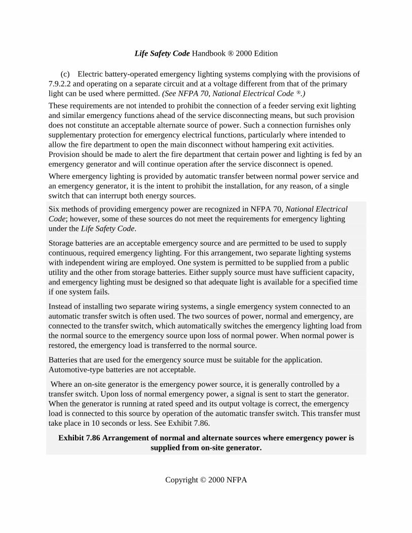
Where an on-site generator is the emergency power source, it is generally controlled by atransfer switch. Upon loss of normal emergency power, a signal is sent to start the generator.When the generator is running at rated speed and its output voltage is correct, the emergencyload is connected to this source by operation of the automatic transfer switch. This transfer musttake place in 10 seconds or less. See Exhibit 7.86.
Exhibit 7.86 Arrangement of normal and alternate sources where emergency power issupplied from on-site generator.

Life Safety Code Handbook ® 2000 Edition
Copyright © 2000 NFPA
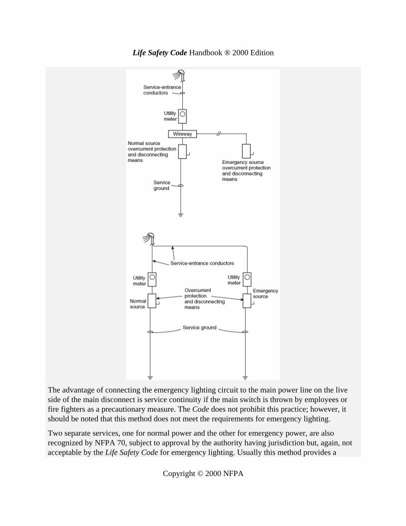
Exhibit 7.87 shows two methods of obtaining an emergency power supply by connection aheadof the service disconnecting means. Although not prohibited by NFPA 70, this method does notcomply with the requirements for emergency lighting of the Life Safety Code and might not beacceptable to the authority having jurisdiction. Before considering this method to supplyemergency power for other than emergency lighting, the reliability of the utility system in thearea must be evaluated, and the risk to building occupants must be carefully thought out. Thisarrangement only provides protection from electrical failures in the occupancy, such as blownfuses, tripped circuit breakers, or a localized fire at such locations as the electrical service ordistribution panels. In such instances, the availability of the emergency source is dependent onthe reliability of the public utility.
Exhibit 7.87 Two methods (not Life Safety Code compliant) of obtaining an emergencysource by connection ahead of service disconnecting means.
Life Safety Code Handbook ® 2000 Edition
Copyright © 2000 NFPA
The advantage of connecting the emergency lighting circuit to the main power line on the liveside of the main disconnect is service continuity if the main switch is thrown by employees orfire fighters as a precautionary measure. The Code does not prohibit this practice; however, itshould be noted that this method does not meet the requirements for emergency lighting.
Two separate services, one for normal power and the other for emergency power, are alsorecognized by NFPA 70, subject to approval by the authority having jurisdiction but, again, notacceptable by the Life Safety Code for emergency lighting. Usually this method provides a
Life Safety Code Handbook ® 2000 Edition
Copyright © 2000 NFPA
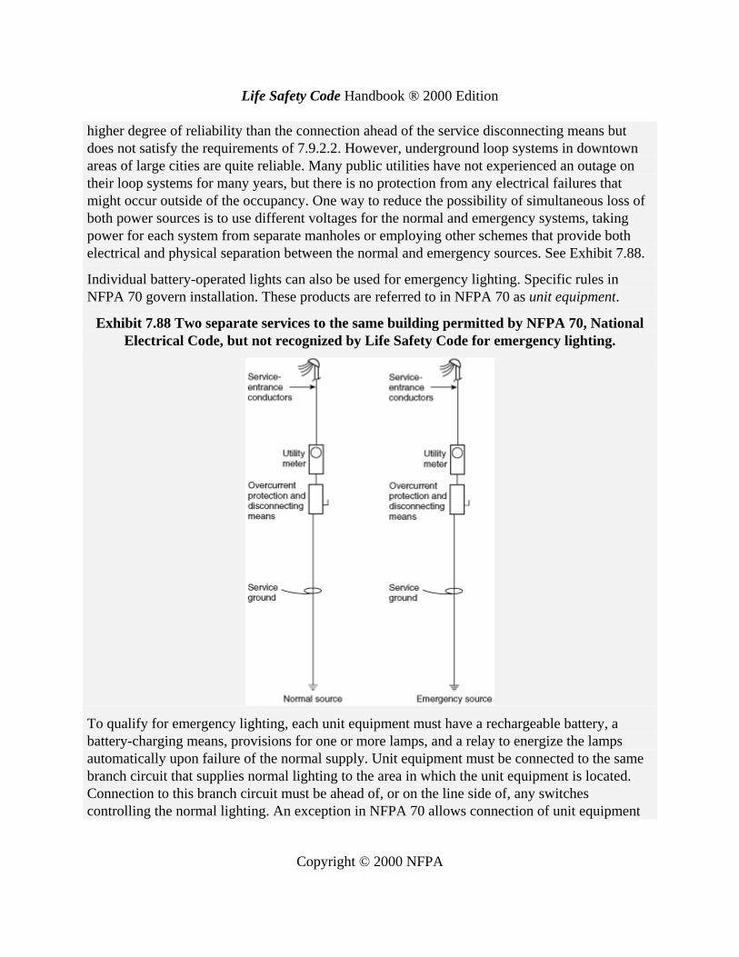
higher degree of reliability than the connection ahead of the service disconnecting means butdoes not satisfy the requirements of 7.9.2.2. However, underground loop systems in downtownareas of large cities are quite reliable. Many public utilities have not experienced an outage ontheir loop systems for many years, but there is no protection from any electrical failures thatmight occur outside of the occupancy. One way to reduce the possibility of simultaneous loss ofboth power sources is to use different voltages for the normal and emergency systems, takingpower for each system from separate manholes or employing other schemes that provide bothelectrical and physical separation between the normal and emergency sources. See Exhibit 7.88.
Individual battery-operated lights can also be used for emergency lighting. Specific rules inNFPA 70 govern installation. These products are referred to in NFPA 70 as unit equipment.
Exhibit 7.88 Two separate services to the same building permitted by NFPA 70, NationalElectrical Code, but not recognized by Life Safety Code for emergency lighting.
To qualify for emergency lighting, each unit equipment must have a rechargeable battery, abattery-charging means, provisions for one or more lamps, and a relay to energize the lampsautomatically upon failure of the normal supply. Unit equipment must be connected to the samebranch circuit that supplies normal lighting to the area in which the unit equipment is located.Connection to this branch circuit must be ahead of, or on the line side of, any switchescontrolling the normal lighting. An exception in NFPA 70 allows connection of unit equipment

Life Safety Code Handbook ® 2000 Edition
Copyright © 2000 NFPA
directly to a branch circuit from a panelboard that also supplies a minimum of three normallighting circuits to the area in which the unit equipment is installed. The overcurrent deviceprotecting this unit equipment circuit must be provided with a lock-on feature that will preventaccidental disconnection.
7.9.2.3
Emergency generators providing power to emergency lighting systems shall be installed, tested,and maintained in accordance with NFPA 110, Standard for Emergency and Standby PowerSystems. Stored electrical energy systems, where required in this Code, shall be installed andtested in accordance with NFPA 111, Standard on Stored Electrical Energy Emergency andStandby Power Systems.
7.9.2.4*
Battery-operated emergency lights shall use only reliable types of rechargeable batteriesprovided with suitable facilities for maintaining them in properly charged condition. Batteriesused in such lights or units shall be approved for their intended use and shall comply with NFPA70, National Electrical Code®.
A.7.9.2.4
Automobile-type lead storage batteries are not suitable by reason of their relatively short lifewhen not subject to frequent discharge and recharge as occurs in automobile operation.For proper selection and maintenance of appropriate batteries, see NFPA 70, National ElectricalCode.
7.9.2.5
The emergency lighting system shall be either continuously in operation or shall be capable ofrepeated automatic operation without manual intervention.
7.9.3 Periodic Testing of Emergency Lighting Equipment.
A functional test shall be conducted on every required emergency lighting system at 30-dayintervals for not less than 30 seconds. An annual test shall be conducted on every requiredbattery-powered emergency lighting system for not less than 11/2 hours. Equipment shall be fullyoperational for the duration of the test. Written records of visual inspections and tests shall bekept by the owner for inspection by the authority having jurisdiction.Exception: Self-testing/self-diagnostic, battery-operated emergency lighting equipment thatautomatically performs a test for not less than 30 seconds and diagnostic routine not less thanonce every 30 days and indicates failures by a status indicator shall be exempt from the 30-dayfunctional test, provided that a visual inspection is performed at 30-day intervals.
7.10 MARKING OF MEANS OF EGRESS
In the fatal Westchase Hilton Hotel fire, which occurred in Houston, Texas, March 1982,
Life Safety Code Handbook ® 2000 Edition
Copyright © 2000 NFPA
“several people were confused by the exit markings or the similarity of exit doors and adjacentstorage room doors. The directional exit signs within the exit foyers at the ends of the hotelcorridors indicated that the exit path from this point would be perpendicular to the exit accesscorridor. Some of the occupants moved toward the locked storage room doors and away from theexits.”28 See also commentary on Sections 7.8 and 7.9.

10011003.2.2.2.1
2001 CALIFORNIA BUILDING CODE
1--105
Chapter 10
MEANS OF EGRESSNOTE: This chapter has been revised in its entirety.
For qualified historical buildings or properties, see Chapter 34, Division II.
SECTION 1001 � ADMINISTRATIVE
1001.1 Scope. Every building or portion thereof shall be providedwith a means of egress as required by this chapter. A means ofegress is an exit system that provides a continuous, unobstructedand undiminished path of exit travel from any occupied point in abuilding or structure to a public way. Suchmeans of egress systemconsists of three separate and distinct elements:
1. The exit access,
2. The exit, and
3. The exit discharge.[For DSA/AC] NOTE: For additional means of egress provisions
adopted byDSA/AC, seeChapters 11A for public housing, 11B for pub-lic accommodations, 11C for motor vehicle fuel facilities and Chapter34, Division II for historical buildings.
1001.2 Standards of Quality. The standards listed below that arelabeled a �UBCStandard� are also listed inChapter 35, Part II, andare part of this code.
[For SFM] The standards listed below that are labeled an�Adopted Standard� are also listed in Chapter 35, Part III, andare part of this code.
1. Power doors.
1.1 UBC Standard 10-1, Power-operated Egress Doors
1.2 UBC Standard 7-8, Horizontal Sliding Fire Doors Usedin a Means of Egress
2. Stairway numbering system.
UBC Standard 10-2, Stairway Identification
3. Hardware.
4. Smoke-containment systems. Adopted standard�ICBO ESAC 77, Acceptance Criteria for Smoke-Containment SystemsUsed with Fire-Resistive Elevator Hoistway Doors and Frames.
UBC Standard 10-4, Panic Hardware
SECTION 1002 � DEFINITIONS
For the purpose of this chapter, certain terms are defined as fol-lows:
AISLE ACCESSWAYS are that portion of an exit access thatleads to an aisle.
EXIT. See Section 1005.1.
EXIT ACCESS. See Section 1004.1.
EXIT DISCHARGE. See Section 1006.1.
EXIT DOOR. See Section 1003.3.1.1.
MEANS OF EGRESS. See Section 1001.1.
MULTITHEATER COMPLEX is a building or portionthereof containing two or more motion picture auditoriums thatare served by a common lobby.
PANICHARDWARE is a door-latching assembly incorporat-ing an unlatching device, the activating portion of which extendsacross at least one half the width of the door leaf on which it isinstalled.
PHOTOLUMINESCENT is the property of emitting light asthe result of absorption of visible or invisible light, which contin-ues for a length of time after excitation.
PRIVATE STAIRWAY is a stairway serving one tenant only.
PUBLIC WAY is any street, alley or similar parcel of landessentially unobstructed from the ground to the sky that is deeded,dedicated or otherwise permanently appropriated to the publicfor public use and having a clear width of not less than10 feet (3048 mm).
SELF-LUMINOUS means powered continuously by a self-contained power source other than a battery or batteries, such asradioactive tritium gas. A self-luminous sign is independent ofexternal power supplies or other energy for its operation.
SMOKE-PROTECTED ASSEMBLY SEATING is seatingserved by a means of egress system and is not subject to blockageby smoke accumulation within or under a structure.
SECTION 1003 � GENERAL
1003.1 Means of Egress. All portions of the means of egressshall comply with the applicable requirements of Section 1003.
1003.2 System Design Requirements. The general designrequirements specified in this section shall apply to all three ele-ments of the means of egress system, in addition to those specificdesign requirements for the exit access, the exit and the exit dis-charge detailed elsewhere in this chapter.
1003.2.1 Use.
1003.2.1.1 General. The building official shall assign a use cate-gory as set forth in Table 10-A to all portions of a building. Whenan intended use is not listed in Table 10-A, the building officialshall establish a use based on a listed use that most nearlyresembles the intended use.
1003.2.1.2 Change in use. No change in use or occupancy shallbe made to any existing building or structure unless the means ofegress system is made to comply with the requirements of thischapter for the new use or occupancy. See Section 3405.
1003.2.2 Occupant load.
1003.2.2.1 General. The basis for the design of the means ofegress system is the occupant load served by the various compo-nents of such system.
1003.2.2.2 Determination of occupant load. Occupant loadsshall be determined in accordance with the requirements of thissection.
1003.2.2.2.1 Areas to be included. In determining the occupantload, all portions of a building shall be presumed to be occupied atthe same time.
EXCEPTION:Accessory use areas that ordinarily are used only bypersons who occupy the main areas of an occupancy shall be providedwith means of egress as though they are completely occupied, but theiroccupant load need not be includedwhen computing the total occupantload of the building.
CA
CACACAC
LLLLLLL
CACAC
LLLLL
CACAC
LLLLL

1003.2.2.2.21003.2.6
2001 CALIFORNIA BUILDING CODE
1--106
1003.2.2.2.2 Areas without fixed seats. For areas without fixedseats, the occupant load [for HCD 1 & HCD 2] permitted in anybuilding or portion thereof shall not be less than the number deter-mined by dividing the floor area under consideration by the [forHCD1&HCD2] square feet per occupant load factor assigned tothe use for such area as set forth in Table 10-A.
[For HCD 1 & HCD 2] When the square feet per occupant isnot given for a particular occupancy, it shall be determined by theenforcing agency based on the area given for the occupancywhichit most nearly resembles.
The occupant load for buildings or areas containing two ormoreuses or occupancies shall be determined by adding the occupantloads of the various use areas as computed in accordance with theapplicable requirements of Section 1003.2.2.2.Where an individual area has more than one proposed use, the
occupant load for such area shall be determined based on that usethat yields the largest occupant load.
1003.2.2.2.3 Areas with fixed seats. For areas having fixedseats, the occupant load for such areas shall be determined by thenumber of fixed seats installed therein.
For areas having fixed benches or pews, the occupant load shallnot be less than the number of seats based on one person for each18 inches (457mm) of length of pewor bench.Where fixed boothsare used in dining areas, the occupant load shall be based on oneperson for each 24 inches (610 mm) of booth length. Where fixedbenches, pews or booths are curved, the larger radius shall deter-mine the booth length.
1003.2.2.2.4 Outdoor areas. The occupant load of yards, patios,courts and similar outdoor areas shall be assigned by the buildingofficial in accordance with their anticipated use. Such outdoorareas accessible to and usable by the building occupants shall beprovidedwith ameans of egress as required by this chapter.Wherean outdoor area exits only through a building, the occupant load ofsuch outdoor area shall be considered in the design of themeans ofegress system of that building.
1003.2.2.2.5 Reviewing stands, grandstands and bleachers.The occupant load for reviewing stands, grandstands and bleach-ers shall be calculated in accordance with Section 1003.2.2.2 andthe specific requirements contained in Section 1008.
1003.2.2.3 Maximum occupant load.
1003.2.2.3.1 Assembly occupancies. The maximum occupantload for an assembly occupancy shall not exceed the occupantload determined in accordance with Section 1003.2.2.2.
EXCEPTION:When approved by the building official, the occu-pant load for an assembly occupancy may be increased, provided themaximum occupant load served does not exceed the capacity of themeans of egress system for such increased number of occupants.
For temporary increases of occupant loads in places of assem-bly, see the Fire Code.
1003.2.2.3.2 Other occupancies. For other than assembly occu-pancies, an occupant load greater than that determined in accord-ance with Section 1003.2.2.2 is permitted; however, the means ofegress system shall comply with the requirements of this chapterfor such increased occupant load.
1003.2.2.4 Minimum occupant load. An occupant load lessthan that determined in accordance with Section 1003.2.2.2 shallnot be used.
1003.2.2.5 Revised occupant load.No increase in occupant loadshall be made to any existing building or structure unless themeans of egress system is made to comply with the requirementsof this chapter for such increased occupant load. See Section 3405.
1003.2.3 Width.1003.2.3.1 General. The width of the means of egress system orany portion thereof shall be based on the occupant load served.1003.2.3.2 Minimum width. The width, in inches (mm), of anycomponent in the means of egress system shall not be less than theproduct determined by multiplying the total occupant load servedby such component by the applicable factor set forth in Table10-B. In no case shall the width of an individual means of egresscomponent be less than the minimum required for such compo-nent as specified elsewhere in this chapter.Where more than one exit or exit-access doorway serves a
building or portion thereof, such calculated width shall be dividedapproximately equally among the means of egress componentsserving as exits or exit-access doorways for that area.
1003.2.3.3 Maintaining width. If the minimum required widthof themeans of egress system increases along the path of exit trav-el based on cumulative occupant loads served, such width shallnot be reduced or otherwise diminished to less than the largestminimumwidth required to that point along the path of exit travel.
EXCEPTION: In other thanGroupH,Divisions 1, 2, 3 and 7Occu-pancies, the width of exterior exit doors from an exit enclosure may bebased on the largest occupant load of all levels served by such exit en-closure multiplied by a factor of 0.2 (5.08) inch per person.
1003.2.3.4 Exiting from adjacent levels.No cumulative or con-tributing occupant loads from adjacent building levels need beconsidered when determining the required width of means ofegress components from a given level.Where an exit enclosure from an upper floor and a lower floor
converge at an intermediate floor, the width of the exit from theintermediate floor shall be based on the sum of the occupant loadsof such upper and lower floors.
1003.2.3.5 Two-way exits. Where exit or exit-access doorwaysserve paths of exit travel from opposite directions, the width ofsuch exit or exit-access doorways shall be based on the largest oc-cupant load served. Where such exit or exit-access doorways arerequired to swing in the direction of exit travel by Section1003.3.1.5, separate exit width for each path of exit travel shall beprovided based on the occupant load of the area that is served.
1003.2.4 Height. Except as specified elsewhere in this chapter,the means of egress system shall have a clear height of not lessthan 7 feet (2134 mm) measured vertically from the walking sur-face to the lowest projection from the ceiling or overhead struc-ture.
EXCEPTION: Sloped ceilings permitted by Section 310.6.1.
1003.2.5 Exit continuity.The path of exit travel along ameans ofegress shall not be interrupted by any building element other thanameans of egress component as specified in this chapter. Obstruc-tions shall not be placed in the required width of a means of egressexcept projections permitted by this chapter. The required capac-ity of a means of egress system shall not be diminished along thepath of exit travel.
1003.2.6 Changes in elevation. All exterior elevation changesand interior elevation changes of 12 inches (305 mm) or morealong the path of exit travel shall be made by steps, stairs or stair-ways conforming with the requirements of Section 1003.3.3.3 orramps conforming with the requirements of Section 1003.3.4.Interior elevation changes of less than 12 inches (305 mm)
along the path of exit travel serving an occupant load of 10 ormoreshall be by ramps conforming with the requirements of Section1003.3.4.[For SFM] In Group I, Division 1.1 Occupancies, any change
in elevation of the floor in a hallway, corridor, exit passageway orexterior exit balcony serving nonambulatory persons shall be bymeans of a ramp.
CACACAC
LLLLLLL
CACACAC
LLLLLLL
CACACAC
LLLLLLL

1003.2.61003.3
2001 CALIFORNIA BUILDING CODE
1--107
EXCEPTIONS: 1. In Group R, Division 3Occupancies andwithinindividual dwelling units of Group R, Division 1 Occupancies.2. Along aisles adjoining seating areas.
1003.2.7 Elevators or escalators. Elevators or escalators shallnot be used as a required means of egress component.
1003.2.8 Means of egress identification.
1003.2.8.1 [For DSA/AC&SFM] Visual exit signs. For the pur-poses of Section 1003.2.8.1, the term �exit sign� shall mean thoserequired signs that visually indicate the path of exit travel withinthe means of egress system.
1003.2.8.2 Where required. The path of exit travel to andwithinexits in a building shall be identified by exit signs conforming tothe requirements of Section 1003.2.8. Exit signs shall be readilyvisible from any direction of approach. Exit signs shall be locatedas necessary to clearly indicate the direction of egress travel. Nopoint shall be more than 100 feet (30 480 mm) from the nearestvisible sign.
EXCEPTIONS: 1. Main exterior exit doors that obviously andclearly are identifiable as exit doors need not have exit signs whenapproved by the building official.2. Rooms or areas that require only one exit or exit access.3. In Group R, Division 3 Occupancies and within individual units
of Group R, Division 1 Occupancies.4. Exits or exit access from rooms or areas with an occupant load of
less than 50 where located within a Group I, Division 1.1, 1.2 or 2Occupancy or a Group E, Division 3 day-care occupancy.
1003.2.8.3 Graphics. The color and design of lettering, arrowsand other symbols on exit signs shall be in high contrast with theirbackground. Exit signs shall have the word �EXIT� on the sign inblock capital letters not less than 6 inches (152mm) in height witha stroke of not less than 3/4 inch (19 mm). The word �EXIT� shallhave letters having a width of not less than 2 inches (51 mm)except for the letter �I� and a minimum spacing between letters ofnot less than 3/8 inch (9.5 mm). Signs with lettering larger than theminimum dimensions established herein shall have the letterwidth, stroke and spacing in proportion to their height.
1003.2.8.4 Illumination. Exit signs shall be internally or exter-nally illuminated. When the face of an exit sign is illuminatedfrom an external source, it shall have an intensity of not less than5 footcandles (54 lx) from either of two electric lamps. Internallyilluminated signs shall provide equivalent luminance and be listedfor the purpose.
EXCEPTIONS: 1. Approved self-luminous signs that provideevenly illuminated letters that have a minimum luminance of 0.06 footlambert (0.21 cd/m2).2. [For SFM] Approved internally illuminated exit signs which use
light-emitting diodes or electroluminescent lamps are not required tohave two electric lamps.
1003.2.8.5 Power source. All exit signs shall be illuminated atall times. To ensure continued illumination for a duration of notless than 11/2 hours in case of primary power loss, the exit signsshall also be connected to an emergency electrical system pro-vided from storage batteries, unit equipment or an on-site genera-tor set, and the system shall be installed in accordance with theElectrical Code. For high-rise buildings, see Section 403.
EXCEPTIONS: 1. Approved self-luminous signs that providecontinuous illumination independent of an external power source.2. [For SFM] The power supply for internally illuminated exit signs
and exit path marking, which do not contain electric lamps, shall nor-mally be provided by the premises� wiring system. In the event of itsfailure, power shall be automatically provided from storage batteriesor an on-site generator set and the system shall be installed in accor-dance with the California Electrical Code.
1003.2.8.6 [For DSA/AC& SFM] Tactile Exit Signage. For thepurposes of Section 1003.2.8.6, the term �tactile exit signs� shallmean those required signs that comply with Section 1117B.5.1-B.
1003.2.8.6.1 [For DSA/AC & SFM] Where required. Tactileexit signs shall be required at the following locations:1. Each grade-level exterior exit door shall be identified by a
tactile exit with the word, �EXIT.�2. Each exit door that leads directly to a grade-level exterior
exit by means of a stairway or ramp shall be identified by a tactileexit sign with the following words as appropriate:
A. �EXIT STAIR DOWN�B. �EXIT RAMP DOWN�C. �EXIT STAIR UP�D. �EXIT RAMP UP�
3. Each exit door that leads directly to a grade-level exteriorexit by means of an exit enclosure or an exit passageway shall beidentified by a tactile exit sign with the words, �EXIT ROUTE.�4. Each exit access door from an interior room or area to a cor-
ridor or hallway that is required to have a visual exit sign, shall beidentified by a tactile exit sign with the words, �EXIT ROUTE.�5. Each exit door through a horizontal exit shall be identified
by a sign with the words, �TO EXIT.�
1003.2.9 Means of egress illumination.
1003.2.9.1 General.Any time a building [for SFM] or portion ofa building is occupied, the means of egress serving the occupiedportion shall be illuminated at an intensity of not less than 1 foot-candle (10.76 lx) at the floor level.
EXCEPTIONS: 1. In Group R, Divisions 2.1.1, 2.2.1, 2.3.1, 6.1.1,6.2.1 and 3 Occupancies and within individual units of Group R, Divi-sion 1 Occupancies.2. In auditoriums, theaters, concert or opera halls, and similar
assembly uses, the illumination at the floor level may be reduced dur-ing performances to not less than 0.2 footcandle (2.15 lx), provided thatthe required illumination be automatically restored upon activation ofa premise�s fire alarm system when such system is provided.3. [For SFM] Sleeping rooms in Group I Occupancies, and sleep-
ing rooms inGroup R,Divisions 2.1, 2.2, 2.3, 6.1 and 6.2Occupancies.
1003.2.9.2 Power supply. The power supply for means of egressillumination shall normally be provided by the premise�s electri-cal supply. In the event of its failure, illumination shall be auto-matically provided from an emergency system for Group I,Divisions 1.1 and 1.2. [For SFM]Occupancies in rooms or areasrequiring two or more exits or exit access doorways, or a com-bination thereof and Group R, Divisions 2.1 and 2.2Occupanciesand for all other occupancies where the means of egress systemserves an occupant load of 100 or more. Such emergency systemsshall be installed in accordance with the Electrical Code.For high-rise buildings, see Section 403.
1003.2.10 Building accessibility. In addition to the requirementsof this chapter, means of egress, which provide access to, or egressfrom, buildings for persons with disabilities, shall also complywith the requirements of Chapter 11.
EXCEPTIONS: 1. [For HCD 1/AC, DSA/AC] For housingaccessibility, see Chapter 11A.
2. [For DSA/AC] For accessibility to public accommodations,commercial buildings and publicly funded housing, see Chapter 11B.
1003.3 Means of egress components. Doors, gates, stairwaysand ramps that are incorporated into the design of any portion ofthe means of egress system shall comply with the requirements ofthis section. These means of egress components may be selec-tively included in the exit access, the exit or the exit discharge por-tions of the means of egress system.
LLLLL
CACAC
CACAC
LLLLL
CACACACAC
LLLLLLLLL
CACACACACACACACACACACACACACACACACACACACACACACA
LLLLLLLLLLLLLLLLLLLLLLLLLLLLLLLLLLLLLLLLLLLLLL
LLLLL
CACAC
CAC
LLL
CAC
LLL
LLLLL
CACAC
CACACAC
LLLLLLL

6' wide egress path, 30' fixture spacing, required UBC FC value = 1FC2'x4' TROFFER W/B30 EM 2L 3000 LUMEN BAL.@10'0"
MICHAEL JOBE ENGINEERING MILPITAS, CA 950353/23/2004 Prepared for: ELECTRICAL CONTRACTORS Project No.: SAMPLE PROJECT
SAMPLE EGRESS PATH EM LIGHTING - Plan ViewScale: 1/8''=1'-0''
12.
27.
51.
68.
58.
35.
18.
12.
17.
32.
55.
68.
53.
29.
1.3
3.1
0.3
6.5
7.7
5.6
8.3
0.2
3.1
8.1
5.3
2.6
7.7
0.6
3.3
.14
1
2
5
6
5
3
1
1
1
3
5
7
5
3
1

6' wide egress path, 20' fixture spacing, required UBC FC value = 1FC32W CF DOWN W/B30 EM 1L 2300 LUMEN BAL.@10'0"
MICHAEL JOBE ENGINEERING MILPITAS, CA 950353/23/2004 Prepared for: ELECTRICAL CONTRACTORS Project No.: SAMPLE PROJECT
SAMPLE EGRESS PATH EM LIGHTING - Plan ViewScale: 1/8''=1'-0''
36.
53.
58.
25.
14.
18.
40.
57.
55.
23.
16.
21.
46.
59.
4.3
9.3
3.6
7.6
0.3
0.2
9.1
3.4
4.6
4.6
5.2
1.2
6.2
0.5
0.7
.54
3
5
5
2
1
1
4
5
5
2
1
2
4
5
4
A1
A1
A1

Lamp Data (Photometrics)
6-volt, 5.0-watt, MR-16 halogen lamp HorizontalLamp Type: MR-16 6V5W
Dual-Lite Part Number: 0110256
Lamp Data (Photometrics)
6-volt, 10-watt, MR-16 halogen lamp HorizontalLamp Type: MR-16 6V10W
Dual-Lite Part Number: 0110261
-8
-6
-4
-2
0
2
4
6
8
10 20 30 40 50 60 70 80
1 0.5 0.3 0.20.1
-12
-10
-8
-6
-4
-2
0
2
4
6
8
10
12
10 20 30 40 50 60 70 80 90 100
10.5
0.30.2
0.1
General InformationThese curves allow a reasonable prediction of the footcandle levels thatmay be expected at various points from the light source. Actual levels ofoutput intensity may differ by as much as ± 15%, due to normal variablesinherent in the manufacturing process.This data should only be used to develop a rough estimate of the typeand number of fixtures required for emergency
lighting layouts. In actual applications, variables such as the color andreflectivity of ceiling, wall and floor surfaces may greatly impactillumination performance.The intent of emergency lighting is to provide a level of illuminationsufficient to allow people to safely exit a building in case of a powerfailure or other emergency. It is advisable to check actual illumination levels on-site to determine if code requirements have been met.
-12
-10
-8
-6
-4
-2
0
2
4
6
8
10
12
10 20 30 40 50 60 70 80 90 100 110
10.5
0.30.2
0.1
MR-16 Lamps (Halogen)
Lamp Data (Photometrics)12-volt, 5.0-watt, MR-16 halogen lamp HorizontalLamp Type: MR-16 12V5W
Dual-Lite Part Number: 0110263
Lamp Data (Photometrics)12-volt, 10-watt, MR-16 halogen lamp HorizontalLamp Type: MR-16 12V10W
Dual-Lite Part Number: 0110264
Lamp PhotometricsHorizontal Isofootcandle Distribution Curves for lamps used
with emergency lighting products and remote fixtures
-8
-6
-4
-2
0
2
4
6
8
10 20 30 40 50 60 70
10.5
0.3 0.20.1

-8
-6
-4
-2
0
2
4
6
8
10 20 30 40 50
10.5
0.30.2
0.1
-8
-6
-4
-2
0
2
4
6
8
10 20 30 40 50 60
10.5
0.30.2
0.1
-10
10 20 30 40 50 60
0.5 0.3 0.20.1
10
01
Sealed Beam Type Lamps (Incandescent)
Sealed Beam Lamps (Incandescent)
-10
10 20 30 40 50 60
0.5 0.3 0.20.1
10
01
Lamp Data (Photometrics)4-volt, 5.0-watt, SBT incandescent lamp HorizontalLamp Type SBT4 Par 36
Dual-Lite Part Number 011025307
Lamp Data (Photometrics)
6-volt, 7.2-watt, SBT incandescent lamp HorizontalLamp Type SBT6 Par 36
Dual-Lite Part Number 011017201
Lamp Data (Photometrics)
12-volt, 7.2-watt, SBT incandescent lamp Horizontal
Lamp Type SBT12 Par 36 Dual-Lite Part Number 011015801
Lamp Data (Photometrics)
6-volt, 7.2-watt, sealed beam incandescent lamp Horizontal
Lamp Type #7672 Par 36 Dual-Lite Part Number 0110172

-14
-12
-10
-8
-6
-4
-2
0
2
4
6
8
10
12
14
10 20 30 40 50 60 70 80
10.5
0.30.2
0.1
-10
10 20 30 40 50 60
0.5 0.3 0.20.1
070 80
-20
-30
10
20
30
1
Sealed Beam Lamps (Incandescent) (cont.)
Lamp Data (Photometrics)
6-volt, 25-watt, sealed beam incandescent lampHorizontal
Lamp Type #4510 Par 36
Dual-Lite Part Number 0110041
Lamp Data (Photometrics)
12-volt, 25-watt, sealed beam incandescent lampHorizontal
Lamp Type #4446 Par 36
Dual-Lite Part Number 0110132
-20
20 40 60 80 100 120
20
0 1 0.5 0.3 0.2 0.1
Lamp Data (Photometrics)
12-volt, 18-watt, sealed beam incandescent lampHorizontal
Lamp Type #4414 Par 36
Dual-Lite Part Number 0110128
-10
10 20 30 40 50 60
0.5 0.3 0.20.1
10
01
20
-20
70 80 90
Lamp Data (Photometrics)
6-volt, 12-watt, sealed beam incandescent lampHorizontal
Lamp Type #4042 Par 36
Dual-Lite Part Number 0110175
Lamp Data (Photometrics)
6-volt, 18-watt, sealed beam incandescent lampHorizontal
Lamp Type #4014 Par 36
Dual-Lite Part Number 0110127
-20
20 40 60 80 100
0.5 0.3 0.2 0.1
20
0120
1

-10
-8
-6
-4
-2
0
2
4
6
8
10
10 20 30 40 50 60 70 80
10.5
0.30.2
0.1
-20
20 40 60 80 100
0.5 0.30.2
0.1
20
01
10
-10
-14
-12
-10
-8
-6
-4
-2
0
2
4
6
8
10
12
14
10 20 30 40 50 60 70 80 90 100
10.5
0.30.2
0.1
Sealed Beam Lamps (Halogen)
-14
-12
-10
-8
-6
-4
-2
0
2
4
6
8
10
12
14
10 20 30 40 50 60 70 80 90 100 110 120
10.5
0.30.2
0.1
Dual-Lite ● 60 Fieldstone Court ● Cheshire, Connecticut 06410-1212 ● Tel: (203) 699-2000 ● Fax: (203) 699-2059 ● Web Site: www.dual-lite.comCopyright© Dual-Lite, a Hubbell Lighting Inc. brand - All Rights Reserved - Specifications subject to change without notice. Printed in U.S.A. 0601600 7/03
Lamp Data (Photometrics)
6-volt, 20-watt, sealed beam halogen lamp Horizontal
Lamp Type #H7554 Par 36
Dual-Lite Part Number 0110157
Lamp Data (Photometrics)12-volt, 12-watt, sealed beam halogen lamp Horizontal
Lamp Type H7557 Par 36
Dual-Lite Part Number 0110190
-20
20 40 60 80
0.5 0.30.2
0.1
20
01
10
-10
10 30 50 70
Lamp Data (Photometrics)
6-volt, 8-watt, sealed beam halogen lamp HorizontalLamp Type #7551 Par 36Dual-Lite Part Number 0110162
Lamp Data (Photometrics)
6-volt, 12-watt, sealed beam halogen lamp HorizontalLamp Type #H7553 Par 36Dual-Lite Part Number 0110159
Lamp Data (Photometrics)
12-volt, 8-watt, sealed beam halogen lamp HorizontalLamp Type #H7555 Par 36Dual-Lite Part Number 0110189