lif1 ultracare la.3 at the cutting edge of industry
TRANSCRIPT

lif1@1 ULTRACARE La.3 At the Cutting Edge of Industry
FSP 180/220 THROUGH FEED FOUR
SIDE PLANING MACHINE
INSTRUCTION MANUAL No.2022/3

MANUFACTURERS E.C. DECLARATION OF CONFORMITY
The following machine has undergone "Conformity Assessment" and has undergone Self Assessment in accordance with:-
Schedule IV of the Supply of Machinery (Safety) Regulations 1992 and Amendment No. 2063
COMPANY
Wadkin Ultracare Limited Franks Road Hilltop Industrial Park Bardon Leicestershire LE67 1TT
RESPONSIBLE PERSON
Mr J P Smith (Director)
MACHINE DESCRIPTION
TYPE
MODEL
Four Sided Planer
FSP
DIRECTIVES COMPLIED WITH
Supply of Machinery (Safety) Regulations 1992 Amendment No. 2063 1994 Draught Proposal GEN/TC 142 ISO 9001 Part 1
SIGNED ON BEHALF OF WADKIN UL TRACARE LTD .
........................... ~ ...................... .

BE CAREFUL THIS MACHINE CAN BE DANGEROUS
IF IMPROPERLY USED
Always use guards. Keep clear until rotation has ceased.
Always operate as instructed and in accordance with good practice.
Read instruction manual before installing, operating or maintaining machine.
Manufactured by : Wadkin UltraCare Franks Road Hilltop Industrial Park Bardon Leicestershire, LE67 1 TT United Kingdom
Telephone No.:+44(0)116 276 9111 Fax No. :+44(0)116 259 8138
~ NATIONAL
ACCREDITATION Of CEMlflCATION
BODIES

PREFACE
IMPORTANT
It is our policy and that of our suppliers to constantly review the design ana capacity of our products. With this in mind we would remind our customers that while the dimensions and performance data contained herein are correct at the time of going to pressf it is possible that due to the incorporation of the latest deve opments to enhance performance, dimensions and suppliers may vary from those illustrated.
This manual is written as a general guide. A typical machine is shown to illustrate the main features. For reason of clarity certain guards, safety devices and machine parts may not be shown on particular illustrations but MUST be fixea to the machine, correctly set and working before operating
Failure to comply with instructions in this manual may invalidate the guarantee ·

IMPORTANT
SAFETY PROCEDURES AND CONSIDERATIONS
To ensure safe working conditions, persons operating and assisting with the operation of this machine must ensure that they read and fully understand the instructions given within this manual and have received sufficient training in the use of the machine and the safety aspects to be observed.
Note:- Persons under the age of 18 years must not operate the machine except during the course of training under the supervision of a trained operator.
A) POINTS TO NOTE BEFORE OPERATING OR ASSISTING WITH THE OPERATION OF THE MACHINE.
1) .. You have read and understand the operation and safety aspects of the machine and have been checked out by a qualified supervisor.
2) The machine is supplied with full safe guarding. The machine shall not be operated unless the safe guardings are in position and are functional.
3) Cutters/blades are the correct type, suitable fcir the machine and working conditions, rotate in the correct direction of cut, are sharp and correctly fitted.
4) Correct spindle and speeds are selected for the cutter equipment and working conditions.
5) Loose clothing is either removed or securely fastened back and jewellery removed.
6) Adequate working space and lighting is provided.
7) All dust extraction equipment is switched on, properly adjusted and working adequately.
8) The machine is securely installed (refer to installation section within this manual).
9) The machine should only be used for cutting wood or materials with physical and technological characteristics similar to wood, and for which the chip or particle removal process is similar.
10) Only use tooling that complies with prEN 847-1. Sawblades made of High Speed Steel (HSS) MUST NOT be used. .

8) DURING MACHINING:-
1) Wear suitable protective clothing e.g, approved eye protection, ear defenders and dust masks. Gloves shall be worn when handling tooling.
2) Stop the machine using the emergency stop or at the mains isolator before making adjustments, cleaning or carrying out maintenance.
3) Keep the floor area around the machine clean and free from wood refuse. Do not allow the floor around the machine to be come slippery.
4) Stop the machine and report immediately to a person in authority any actual or potential malfunction or operator hazard. Do not attempt to repair or rectify the machine unless qualified or authorised to do so.
5) The operator must not leave the machine running whilst unattended.
6) Never by-pass interlocks.
WARNING:-
Failure to observe correct operatin!;J procedures prior to and during operation of this machine can result in severe iniury. •
DO NOT attempt to operate the machine while under the influence of anything that reduces your alertness.

HEAL TH AND SAFETY
The CE mark on this machine signifies that an EC declaration of conformity is drawn up indicating that the machine is manufactured in accordance with the Essential Health and Safety Requirements of the 'Supply of Machinery {Safety) Regulations 1992'.
The 'requirements for supply of relevant machinery' in the General Requirement of the Regulations are not only that the machine satisfies the relevant essential health and safety requirements, but also that 'the manufacture ...... carries out the necessary research or tests on components, fittings or the complete machine to determine whether by its design or construction the machine is capable of being erected and put into service safely'.
Persons who install this machine. have duties unde.r the 'Provision and Use of Work Equipment Regulations 1992'. An indication of these duties is given in the following extracts, but the user should be familiar with the full implications of the regulations.
REGULATION 5 requires that;
Every employer shall ensure that work equipment is so constructed or adapted as to be suitable for the purpose for which it is used or provided.
. In selecting work equipment, every employer shall have regard to the working conditions and to the risks to health and safety of persons which exist in the premises or undertakings in
. which that work equipment is to be used and any additional risk posed by the use of that work equipment.
Every employer shall ensure that work equipment is used only for the operations for which, and under conditions for which, it is suitable.
In this regulation 'suitable' means suitable in any respect which it is reasonably foreseeable will affect health or safety of any person:
The Provision and Use of Work Equipment Regulations also include requirements as follows:-
regulation 6 - maintenance
regulation 7 - specific risks
regulation 8 - information and instructions
regulation 9 - training
Note:-
Attention is drawn to those requirements of the 'Woodworking Machines Regulations 1974' which are not replaced by the Supply of Machinery {Safety) Regulations or other, eg; Regulation 13 of the Woodworking Machinery Regulation, - 'Training', still applies.
Whilst the prime duty for ensuring health and safety rests with employers, employees too have legal duties, particularly under sections 7 and 8 of the Health and Safety at Work Act. They include:
Taking reasonable care for their own health and safety and that of others who may be affected by what they do or don't do;
co-operating with their employer on health and safety;
not interlering with or misusing anything provided for their health, safety and welfare.
These duties on employees have been supplemented by regulation 12 of the Management of Health and Safety at Work Regulations 1992. One of the new requirements is that employees should use correctly all work items provided by their employer in accordance with their training and the instructions they receive to enable them to use the items safely.

Noise
Noise levels can vary widely from machine to machine depending on the conditions of use. Persons exposed to high noise levels, ·even for a short time, may experience temporary partial hearing loss and continuous exposure to high levels can result in permanent hearing damage.
The Noise at Work Regulations 1989 place legal duties on employers to prevent damage to hearing.
There are three action levels of noise defined in regulation 2;
The first action level;-
a daily personal noise exposure (LEe.•) of 85dB(A)
The second action level;-
a daily personal noise exposure (LEe.o) of 90dB(A)
The peak action level
a peak sound pressure of 200 pascals (140dB re 20pa)
The exposure level is obviously influenced by the emission level of all the equipment in use.
Emissions levels for machines are provided in the particular machine instruction manual.
These levels are measured in accordance with ISO 7960 under certain specified test conditions, they do not necessarily represent the highest noise level, which is influenced by many factors, eg number of spindles in operation, type and condition of work piece, spindle speeds etc.
For regulations and information on relevant personal protective equipment i.e ear defenders, employers should refer to the Personal Protective Equipment at Work Regulations 1992.
Dust
Wood dust can be harmful to health by inhalation and skin contact and concentrations of small particles in the air can form an explosive mixture.
The Control of Substances Hazardous to Health Regulations (COSHH) 1989 place legal duties on employers to ensure that;-
the exposure of his employees to substances hazardous to health is either prevented or, where this is not reasonably practicable, adequately controlled.
..... adequate control to exposure of employees to a substance hazardous to health shall be secured by measures other than the provision of personal protective equipment.
where the measures taken in accordance with the paragraph above do not prevent or provide adequate control of, exposure to substances hazardous to the health of employees, then in addition to tacking those methods, the employer shall provide those employees with such suitable personal protective equipment as will adequately control their exposure to substances hazardous to health.
Instructions for Use
Machinery manufactures are required by the Supply of Machinery Safety Regulations to provide comprehensive "Instructions for Use' of equipment, it is important that this information is transmitted to the person using the machine.

CONTENTS
SECTION 1 GENERAL DESCRIPTION
Operating Practice General notes Machine feed systems Noise Common operating problems
Leading Particulars - FSP180 Principal dimensions and capacities Output of motors Standard supplied tooling
Leading particulars - FSP220 Principal dimensions and capacities Output of motors Standard supplied tooling
SECTION 2 INSTALLATION
Lifting and Transportation Unloading Moving Unpacking Cleaning
Installation Data Major dimensions and weight Foundations Supplies and services:-
Noise Emission Values:Machine criteria Machine cutting criteria Material criteria Noise emission chart
Electrical supply Pneumatics Exhaust Air requirements
Page
1-1 1-3 1-6 1-7
1-9 1-9 1-9
1-10 1-10 1-10
2-1 2-1 2-1 2-1
2-2 2-2
2-2 2-2 2-2 2-2
2-5 2-5 2-5 2-5

SECTION 3 OPERATING INSTRUCTIONS
General Information Safety Safety devices Warnings:-
Machine controls
Notice to operators Before operating machine During machining
3-1 3-1
3-2 3-2 3-2 3-3
Mounting the Cutterblocks ~ne~ 3-5 To change plain bore cutterblocks 3-5
Setting Up the Machine Opening and closing the hood 3-7 Setting bottom head cutterblock 3-7 Setting cut height to bottom head 3-8 Setting cut to fence side head by infeed fence adjustment 3-8 Setting fence side head cutterblock 3-8 Near side head adjustment:-
Top head/beam adjustment:-
Setting through feed rollers:-
Final adjustments
Manual 3-9 Powered 3-1 O
Manual 3-10 Powered 3-12
Shaft mounted Flange mounted
3-12 3-13 3-13
Faults in the Workpiece and their Causes General 3-15
3-15 3-15
Faults caused by tools Faults in grinding and setting
Cleaning the machine
SECTION 4 MAINTENANCE
Scheduled Maintenance General Lubrication and cleaning:-
Spindle drive belt tensioning Side head drive belt check Cleaning
Daily Weekly· Monthly Two monthly Three monthly Yearly
3-15
4-1
4-1 4-1 4-3 4-3 4-3 4-4 4-4 4-4 4-5

Unscheduled Maintenance General Checking cutterblock spindle bearings:-
Bottom head Fence side head Near side head Top head
Removing top throughfeed roller swing Bearing change to top throughfeed roller swings:
Shaft mounted
Replacing drive belts:-Flange mounted
Top and bottom heads Side heads
Removal and replacement of infeed table Replacement of variable speed friction drive ring
Fault Finding Mechanical faults Elimination of vibration Electrical faults
Approved Lubricants
Pneumatic Layout
Motor and Drive Belt Data
SECTION 5 ILLUSTRATED PARTS LIST
Contents Bedplates, fences and bedrolls lnfeed table lnfeed fence lnfeed gate assembly Bottom head adjustment Fence side head adjustment Near side head - Manual adjustment Near side head - Powered adjustment Near side head hood Side head belt tension Top head hood chipbreaker - FSP180 Top head and beam vertical adjustment - Manual Top head and beam vertical adjustment - Powered Raise and fall gearbox for beam and top head Spindle assembly Shaft mounted throughfeed roll Flange mounted throughfeed roll· Driven outfeed bedroll Top head hood and chipbreaker - FSP220 Gearboxes and drive shafts - Fixed speed Gearboxes and drive shafts - Variable speed Drive to outfeed bedroll Pneumatics
4-7
4-7 4-8 4-9 4-9 4-11
4-11 4-12
4-13 4-14 4-15 4-16
4-19 4-19 4-19
4-23
4-25
4-27
5-3 5-5 5-7 5-9
5-11 5-13 5-15 5-17 5-19 5-21 5-23 5-25 5-27 5-29 5-31 5-33 5-35 5-37 5-39 5-41 5-43 5-45 5-47

SECTION 1 GENERAL DESCRIPTION
OPERATING PRACTICE
General notes on all models of Wadkin Planing and Moulding machines.
These are general notes and some of the operating practices may not be available or applicable to individual machines.
A planing and moulding machine produces planed or moulded surfaces on all four sides of lengths of timber, both hard and softwood, at feed speeds determined by the cutter equipment and quality of surface finish required.
A series of 'ridges' (cutter marks) is created on the surface of the timber as it is moved past a rotating cutterblock (see Fig 1 ). The quality of surface finish is determined by the number of knife marks per 25mm (1 ") (the pitch of the cutter marks). The closer the pitch the better the quality of surface finish.
FIG 1
From experience a good quality surface finish has knife marks at a pitch of 1.5 to 2mm. Reducing the pitch improves the surface finish but increases the wear on the cutters, increasing the pitch reduces the quality.
The number of cutter knives in a cutterblock will only be effective· when all are rotating in precisely the same cutting circle. Two main factors influence this.
a. The fit of the cutterblock on the spindle
b. The concentricity of grinding
The conventional method of mounting a cutterblock is to lock a plain bore block on to a plain ground spindle with a locknut. The tolerances in each component give a possible 0.05mm (0.002") clearance in the bore and thus eccentric running (see Fig 2).
FIG 2
The Wadkin hydrofix locking system eliminates this clearance by pressurising the bore of the cutterblock onto spindle (see Fig 3).
!+t+l!tr
ltiJ)ltJ
FIG3
1-1

1-2
Axial locking is not required and a simple safety collar is recommended to prevent the cutterblock moving axially, or rotating on the spindle, if the hydraulic pressure is not applied.
Because the Hydrofix locking is also used while the knives in the· cutterblock are ground in the toolroom, it can be seen that the high accuracy of the grinding process is transferred directly to the planing and moulding machine.
This accuracy, together with the true running of the precision spindle of the moulder, reduces the running of the knives to within 0.002 to 0.005mm of the true cutting circle. However, this minimum run-out is still such that only one knife leaves a finishing cut, no matter how many are in the block.
To ensure that all the knives in a cutterblock run in an absolutely true cutting circle, the technique of jointing is used, in which the jointing 'stone' trues all the knives while rotating at cutting speed in the planing and moulding machine (see Fig 4).
FICi
It can be seen that for a given spindle speed and quality of surface finish (pitch of knife marks), the feed speed may be increased in direct relationship to the number of knives in the cutterblock.
Cuttermark pitch~ Feed speed in mm per min Block rpm x No of cutters
For example 12 x 1000 6000 x 1 = 2mm pitch
for a spindle running at 6000 rpm and a feed speed of 12m/min and unjointed (1 knife finishing).
Jointing a 4 knife block and increasing the feed speed to ((4 x 12)) ie: 48M/min gives the same resulting pitch (finish).
Jointing can be carried out on straight planing blocks - 'straight' jointing, and on profile blocks - 'plunge' jointing.
The process of jointing. which can be repeated several times, produces a heel on the knives.
In the interests of quality this must not exceed a certain width. This is approx 0.5mm on softwood and 0.7mm on hardwood (see Fig 5).
FIG 5
Both high speed steel and carbide knives may be jointed but require a different composition of jointing stone.
An alternative method of increasing output is to increase the spindle speed thus permitting a faster speed for a given quality of surface finish. 'Wadkin' can offer alternative spindle speeds up to a maximum of 15000 rpm. This highest spindle speed, achieved with very high precision, lubricated for life bearings, permits a 2112 x (250%) increase in output without jointing.

Typical surface finish pitch values for different applications are listed:
Sawmilling Joinery Strip moulding Furniture
1.5to 2.5mm 1.5 to 2.0mm 1.3 to 2.0mm 1.0 to 1.5mm
Machine Feed Systems
Push Feed (Fig 6)
This original method of feeding a planing and moulding machine is still provided, and consists of two top driven and two opposed bottom driven feed rolls at the infeed end of the machine. An idle roller and pad pressures between the cutterheads controls the timber down to the bed and across to the fence as it passes through the machine. It follows that if bowed or twisted stock is fed to the cutters, that while a perfect profile will be produced, the component will be as twisted or bowed as it entered.
FIG 6
The pushfeed machine has the disadvantage that the last piece of timber is always left in the machine; traction stops as the trailing end leaves the feedworks. The last piece can only be retrieved by following with a scrap length or by reverse feeding, in which case the component is unfinished.
Through feed (Fig 7)
Through feed was developed to overcome the handicap of the last piece remaining in cut, and to eliminate the heavy top and side pressures.
Drive rolls between each cutterhead feed the components through the machine.
I
~$-~~$-I -e-8l$- -$--$- -EB- I -$-
FIG 7
A Jong infeed table before the first bottom head, together with the much lighter loading on the timber, enables straightening of the component i.e.: the underside being straightened (surfaced) at the first bottom head, and the edge (fence side) being straightened at the first side head (see Fig 8).
FIG 8
An alternative method of straightening combines underside and fence side straightening, using a single cutterblock, planing the underside in the normal way and machining a reference edge with a rebating disc on the same block (see Fig 9).
FIG 9
1-3

1-4
The above straightening techniques are most successful on timber which is bowed and has square ends, typical of softwood. For timber which is twisted and has out-of-square ends, typical of some hardwoods, an alternative technique is provided.
Grooved bed straightening (Fig 10)
In this design, grooving cutters on the first bottom head permit support in the form of rails right through the cut, thus preventing 'dipping' on the twisted timber, or 'buckling' as out-of-square ends come into contact with each other. The grooves on the underside are subsequently machined out on a second bottom head, which is obligatory. Fitting a standard lip plate and cutterblock converts the machine to conventional use.
Hopper Feeding (Fig 11)
To enable the operator to feed timber at relatively fast feed speeds and still maintain butt up, (this may be difficult on short lengths), various types of hopper feed are available.
F!Gll
Components are -stacked in a hopper at the infeed end of the machine and automatically fed one at a time from the bottom of the stack at a rate to ensure 'butt-up'. A slipping device prevents the hopper feed trying to override the machine feed.
Feeding at very high feed speeds, typically on flooring, cladding etc, also presents problems to the operator, again a special feeding device (fast feed table Fig 12) can be provided.
The fast feed table, in line with the machine feed, receives timber from a tilt hoist and cross chains, the driven rollers in· the fast feed table and an overhead hydraulically driven nip roll ensure 'butt up before entry into the machine feedworks, a slipping arrangement prevents overriding.
FIG 12
Outfeed Equipment
Generally used on high feed speed machines, this equipment can be provided at the outfeed end of 'Wadkin' moulders to transfer to ·another process, ie: stack, bundle, wrap, count, etc. Outfeed equipment can be provided and programmed to print on each component some identifying information e.g. Job No. Date, etc. Combinations of these facilities enable the finished components to be presented in a variety of ways at the outfeed end of the machine.

Extra Head Positions
Typically a planing and moulding machine has four heads to machine all four faces, these can be augmented with the addition of other heads. The most common is a second bottom head to ensure clean up on the underside. Where the amount of timber to be removed is great, or where the mould detail is complex it may be necessary to provide an extra bottom head, available as an option.
Splitting (Fig 13)
Splitting is a common operation, usually done on the last bottom head, and often requiring very large horse powers. Such a head is available and may be fitted with anti kick-back fingers to prevent ejection towards the operator. Only one saw can be fitted on the smaller machines, ie. GC.
nc 13
Universal Head
A universal head, either three or four position (always last head on the machine) may be provided to order, or the machine prepared to fit the head at a later date. The three position head may be used as a top head, bottom head or near side head and at any angular position in between. The four position head has the added capability of use as a fence side head.
The universal head . gives greater flexibility for splitting and moulding on a conventional machine, and special pressures, chipbreakers, etc can be
provided to ensure perfect control of the workpiece.
Dial-a-Size Positioning (Fig 14)
On machines which are used for a large variety of small quantity batches of square dressed material, the set up time can be reduced by fitting. Dial-aSize positioning.
FIG 14
The near side head horizontal adjustment is motorised and fitted with an encoder, the motorised vertical movement of the top head and feed is also fitted with an encoder.
A programmable memory stores the widths and thicknesses of the workpieces to be produced and on command the two heads are repositioned to the preset dimensions. In a similar manner, where components of random width are machined (eg. Table tops, see Fig 15). The machine can be arranged to sense the width of the incoming pieces and automatically move the outside head to the required position.
Whilst being a slow operation, (butt feeding is nof possible and the feed speed is slow), the facility does have great advantage to some users.
FIG 15
-~.,... =:::=:.....~~ \-=--··
l-5

1-6
Feed Enhancement
The 'Wadkin' push feed and through feed syst€ms are the result of years of experience in the planing and moulding industry, and for the great majority of work are exemplary. However, the great variety of timbers available, and the differ€nt conditions in which they are presented to the machine is acknowledged in the various options available to enhance feeding and minimise bed wear.
Bed Lubrication
A lubricant is introduced to the surface of the machine bed, from a manual or auto pump; this reduces friction, improves feeding capability and reduces bed wear.
An alt€rnative; of introducing air between the timber and the bed of the machine, can be provided for those machines that do not have a second bottom head io machine off the small amount of oil introduced to the underside of the timber or where the material being machined must not in any circumstances be contaminated with oil.
Feed Rolls
The top driven feed rolls of a through feed moulder are normally spring loaded down onto the workpiece.
The required amount of load can vary with the nature of the work being run, although as a general rule it must be as light as practicable, and variation in rough timber thickness will of course increase the load as the feed rolls yield more. Adjustment of the loading is done at each individual roll.
Pneumatic loading can be provided, this has a number of advantages. The loading does not vary with any variation in lift, and the amount of loading can be changed more easily, using an air regulator valve.
One regulator controls the loading to rolls before the top head, and the other regulator controls the rolls after to top head.
Noise
Planing and moulding machine, by virtue of the number of cutter heads and the speed of the heads, produce high noise levels, typically between 95dB and 115dB when cutting.
The woodworking machine regulations require that an operator is not to be subjected to noise levels above 90dBA for 8 hours, some precautions are therefore required and a safety/acoustic cover can be supplied for this purpose.
It should be noted however, that even with a sound enclosure, under some circumstances, because of 'break out' (at say the infeed end), the noise level at the operating positions will be above 90 dBA.
For personal safety ·reasons the operator should wear ear defenders.
WARNING Before operating the machine read the preface and notice to operators in section 3, Operating Instructions.

COMMON OPERATING PROBLEMS
When resolving problems, always work in a systematic logical sequence. Work from the infeed end of the machine through to the outfeed end, checking for faults in a progressive manner.
In this way faults will not be overlooked and remedial action can be taken where needed.
Set (spring loaded) top pressure with minimum amount of lift. Set side guide just up to timber ie; not clear, not trapping. When feeding wide pieces, on a through feed machine it is normally better to space feed roller than have a solid bank, (see Setting up the Machine).
FAULT
Check
FAULT
Check
FAULT
Check
FAULT
Check
Timber stops in machine
Setting of cutterblocks to table and fences. Amount of pressure applied to feedrolls (pneumatic or spring). Sharpness of cutters. Yield of chipbreakers. Tightness of side guide onto timber. Oil level of bed lubrication pump. Position of feed rolls on workpiece.
Ripples appear on surface of workpiece
Setting of cutterblocks to table or fences. Pressure is applied to feedrolls (pneumatic or spring). Sharpness of cutters. Chipbreakers are set correctly and have sufficient pressure to control timber. All locks are applied. Tooling is suitable for the work.
Bumps on infeed or outfeed end of workpieces
Setting of cutterblocks to table and fences. Sharpness of cutters. Chipbreakers are set correctly and have sufficient pressure to control timbe~ -All locks are applied. Bed and fences for build up of resin or chips.
Timber runs away from fence
Near side head chipbreaker is in contact with timber. Side guide after fence sidehead is adjusted correctly. Mating faces of feed rolls and spacers are clean.
1-7

1-8
FAULT
Check
Machine will not straighten timber
Setting of cutterblocks to table and fences (accurate setting of knife edge to table/fence is critical to obtain perfect straightening). Sharpness of cutters. · . Feed rollers and top/side pressures should not be used before first bottom head. Is the amount of cut set at the infeed end fence and table adequate for the amount of bow in the timber? Is the timber to be straightened a stable section?

LEADING PARTICULARS - FSP 180
Principal Dimensions and Capacities
Maximum size of timber admitted Minimum size of finished work
Maximum cut to all heads
Fixed feed speed Variable feed speed
180mm x 120mm 20mmx6mm
10mm
Sm/min 5-15m/min
Pressure adjustment of pneumatic feed rolls
Shaft mounted feed rolls (per station)
6 bar - reduced
1 off serrated steel 50mm wide x 140mm dia.
Outfeed shaft mounted feed roll only
Flange mounted feed rolls (per station)
Spindle diameter all heads
Max cutting circle diameter all heads Min cutting circle diameter all heads
Output of Motors
Feed motor Bottom head Fence and near side head (shared drive) Top head
Standard Supplied Tooling
1 off polyurethane 50mm wide x 140mm dia.
2 off serrated steel 1 Omm wide x 140mm dia. + 1 off 20mm wide spacer
40mm
127mm 123mm
1.5kw (2.0hp) 4.0kw (5.5hp) 5.5kw (7.5hp) 4.0kw (5.5hp) .
2 off - 1 BOmm long x 125mm diameter 2 knife planing cutterblock complete with 3mm thick HSS planing cutters. ·
2 off - 130mm long x 125mm diameter 2 knife planing cutterblock complete with 3mm thick HSS planing cutters.
1-9

1-10
LEADING PARTICULARS - FSP220
Principal Dimensions and Capacities
Maximum size of timber admitted Minimum size of finished work
Maximum cut to all heads
Fixed feed speed Variable feed speed
220mm x 120mm 20mm x 6mm
10mm
Sm/min 5-15m/min
Pressure adjustment of pneumatic feed rolls
Shaft mounted feed rolls (per station)
6 bar - reduced
1 off serrated steel 50mm wide x 140mm dia.
Outfeed shaft mounted feed roll only
Flange mounted feed rolls (per station)
Spindle diameter all heads
Max cutting circie diameter all heads Min cutting circle diameter all heads
Output of Motors
Feed motor Bottom head Fence and near side head (shared drive) Top head
Standard Supplied Tooling
1 off polyurethane 50mm wide x 140mm dia.
2 off serrated steel 1 Omm wide x 140mm dia. + 1 off 20mm wide spacer
40mm
127mm 123mm
1.5kw (2.0hp) 5.5kw (7.5hp) 5.5kw (7.Shp) 5.5kw (7.5hp)
2 off - 230mm long x 125mm diameter 2 knife planing cutterblock complete with 3mm thick HSS planing cutters. ·
2 off - 130mm long x 125mm diameter 2 knife planing cutterblock complete with 3mm thick HSS planing cutters.

SECTION 2 INSTALLATION
LIFTING AND TRANSPORTATION
Unloading
Verify the weight of the machine (see Installation Data). Ensure that all lifting equipment used is capable of lifting this weight as a minimum.
The machine is despatched from the factory complete with lifting bars and shackles.
Ensure hood is secured down before lifting.
The machine should lift straight if the chain nearest the infeed end is slightly shorter than the other one. The angle between the chains must not exceed 90°.
Remove shackles before opening hood.
Moving
In the process of moving, avoid jolting or vibrating the machine. If the ground is flat the machine can be positioned on wooden plinths and moved by . rollers instead of lifting.
FIG 1 LIFTING MACHINE
Unpacking
Undo the packing and make sure that damage has not occurred during transit; undo the case of accessories and ascertain that the machine is complete with all fittings.
Cleaning
Before levelling the machine, carefully remove the anti-rust material particularly from the bright parts.
Clean the machine with paraffin or diesel and a soft rag. Do not use a substitute - it may precipitate an explosion.
2-1

2-2
INSTALLATION DATA
Major Dimensions and Weight
Length Width Height Height with hood open Weight
Foundations
3050mm 1300mm 1400mm 1900mm 1250 kg
To obtain the best result from the 'Wadkin' woodworking machine it is important that the floor on which the machine is to stand has been prepared and is dry.
The machine must be securely bolted down to a firm, solid and flat base. Wadkin recommended a concrete base 1400mm x 1000mm x 75mm deep. The machine is to be secured by the three supplied M12 anchor type bolts and securing washers.
NOTE: THE MACHINE MUST BE BOLTED DOWN BEFORE USE.
See Foundation Plan for details of floor area required.
Supplies and Services
Electrical Supply
The customer is responsible for an adequate electrical supply. Details of power requirements are provided with the machine.
The machine is delivered with its complete electrical equipment ready for connection.
The electrical connection and schematic diagram are found in the electrical control cubicle of the machine. All that is required is to connect the power supply to the disconnect (isolator) switch at the electrical control cubicle or panel:
POINTS TO CONNECTING SUPPLY
NOTE WHEN THE POWER
Check the voltage, phase and frequency correspond with those on the machine nameplate details.
Check the main fuses are of the correct capacity in accordance with the machine nameplate details.
Connect the incoming supply leads to the appropriate terminals.
Check all connections are sound and that equipment is earthed.
Check the spindle rotation is correct. When looking from the front of the machine the feed rolls should rotate in a clockwise direction. To reverse the rotation on any drive, reverse any two
. of the line lead connections at the incoming supply.
After power has been connected up to the machine isolator, position and secure the hood interlock switch (3) in its horizontal working position (ensure isolator is in the off position)
2
FIG 1 SAFETY HOOD INTERLOCK IN TRANSPORT POSITION.

To position the interlock slacken off the rear mounting bolt (1 ), pivot the interlock unit upwards and secure with mounting bolt (2).
IMPORTANT: ANY ELECTRICAL MODIFICATIONS SHOULD BE CARRIED OUT BY A COMPETENT ELECTRICIAN.
Pneumatic Pressure (where fitted).
Equipment
Where the machine is equipped with pneumatic pressure operated feedrolls, the number of connections are shown on the pneumatic circuit diagram and foundation plan. To make the system operative connect up the air pipes and fittings to a suitable air supply.
The size of the air inlet connection is 114in. BSP female.
The size of the pipe is 8mm O.D. x Smm l.D.
Pressure required is 6 bar (approx 90 psi), see Operating Instructions for feed roll pressures.
An air compressor rated at approximately 2 cu.dm/sec (4 elm) is recommended for pneumatics.
---------------
Exhaust (Dust Extraction) Connections
The size of the connections are given on the Foundation and Dust Extraction Plan.
The part of the air extraction pipe fitted to the exhaust hood should be flexible and detachable. The length of the flexible part is dependant on the way the pipe is used and the adjustment required on the work spindle. As a guide use a flexible pipe one metre long for the lower and fence side spindles and two metres for the top and near side spindles.
The flow of air to the exhaust hoods should be approximately 25 to 30 metres per second.
Volume of Air Required
Total extraction for machine = 2700 elm
Schematic Diagram for Electrical Service
The electrical wiring and schematic diagram will be in the electrical control cubicle of the machine.
2-3

NOISE EMISSION VALUES
Machine criteria
The machine was free standing on a concrete floor, not bolted down and not on any vibration dampening. A flexible pipe connected the machine to the dust extraction. Bedplates prior and after the first bottom head had slotted table lips. · The machine was equipped with a totally enclosed safety cover with foam insulation and outfeed curtain.
Machine cutting criteria
All heads were fitted with 125mm diameter cutterblocks. These were 1 OOmm long on the vertical heads and rotating at 5140 r.p.m whilst the horizontal cutter blocks were 130mm Jong and rotating at 5150 r.p.m. The first bottom head was fitted with an edge reference cutter. The feed speed was 8.8 Ml min.
Material criteria
Material:-
Moisture content:Material length:-
Soft wood joinery grade 12% 1500mm
Material width:- 106mm processed down to 94mm
Material height 64mm processed down to 58mm
Prior machining:- Planed on all four sides
When cutting, two pieces of timber were 'butt' feed throu.
The figures quoted in the noise emission chart are emission levels and not necessarily safe working levels. Whilst there is a correlation between emission levels and exposure levels, this cannot be used reliably to determine whether or not further precautions are required to achieve safe working levels. Factors that influence the actual level of exposure to the work force include the duration of exposure, the characteristics of the work room, sources of noise etc i.e the number of machines and other adjacent processes, also the permissible exposure levels can vary from country to country. Emission levels, however will enable the user of the machine to make a better evaluation of the 'hazard and risk'.
NOISE EMISSION CHART
MODEL:- PLANER TYPE :- FSP 220 SOHZ 415V ·
DECLARED NOISE EMISSION VALUES in accordance with IS04871 Idling Operating
Declared A-weighted sound power level (LwAo) in dB re lpw 91.32 100.05
Declared A-weighted emission sound level (LpAd) in dB re 20uPa at the operators position 77.09 85.82
Environmental correction factor (K) =3
values determined according to specific test code 187960
2-5

SECTION 3 OPERATING INSTRUCTIONS
GENERAL INFORMATION
Safety
The safe operation of woodworking machinery requires constant alertness and close attention to the work in hand.
Read this instruction manual, the Preface and the Safety Notes carefully before operating the machine.
Blunt cutters often contribute to accidents. An efficient machinist knows when sharpening is necessary, but if there is reluctance to spend time on grinding and resetting, the cutters may run beyond their efficient limits and instead of cutting efficiently and smoothly they will tend to chop and snatch at the workpiece. This not only increases the risk of accidents but also lowers the quality of work.
Customers are strongly advised at all times to use high tensile cutterblock bolts which should be tensioned by means of a torque spanner. When choosing cutterblocks ensure they are suitable for the minimum cutting speed of the machine.
It is recommended that personnel involved with the machine are acquainted with the Woodworking Machines Regulations 1974 and also Booklet No. 41 'Safety in the use of woodworking machines', issued by the Department of Employment and available from Her Majesty's Stationary Office. Also BSI Code of Practice 'Safeguarding Woodworking Machines' Part 1 BS 6854.
Only tooling conforming to EN 847-1 shall be used. The speed range marked on the tools must be observed.
Safety Devices
To avoid personal ·injury or accidental damage to the machine sensors and interlocks have been built in which prevent certain operations happening or ensure a certain sequence of events occur in the correct order.
1. Over size timber entering the enclosure will trip a switch and the feedworks will stop. The feedworks must be restarted at the control panel once the timber has been removed.
WARNING:- Only the feed will stop not the spindles. Isolate machine at emergency stop before attempting to remove timber.
2. The enclosure cannot be opened unless the spindles are stationary (C.E machines only).
3.
4.
5.
Opening the enclosure on NON C.E machines causes the brake motors to activate and stop the spindles.
With the enclosure open feed works and spindles will not operate (all machines).
The feed works will not operate unless the spindles are running.
The feed works adjusted vertically spindles are at machines only)
cannot be unless the rest (C.E
3-1

1":::1·~ dim ~~~~~~~~~~~~~~~~~~~~~~~~~~~~
3-2
WARNINGS
Notice to Operators
Read and follow the guide-lines given below in conjunction with the Safety Procedures and Considerations printed at the front of this manual.
The gas struts fitted to the safety enclosure hood and the side head belt tensioner are constantly under internal pressure. At NO time during usage or after replacement should they be dismantled punctured or incinerated.
SAFETY 1•_,'---ENCLOSURE ®[[)
.'. ~ STRUT
jQ3 •
•
~ ----
SIDE HEAD BELT TENSION STRUT
FIG 1 GAS STRUT POSITIONS
Before operatin!;J the machine
Ensure that all guards and fences are securely fitted and correctly adjusted. Guards and other safety devices are NOT to be removed while the machine is in operation. They are there for YOUR SAFETY.
Ensure cutters/blades are the correct type and rotate in correct direction of cut, are sharp and securely fastened.
Remove or fasten loose clothing; confine long hair and remove jewellery, etc. ·
Ensure sufficient working space is provided and that lighting is adequate.
Switch on equipment, correctly.
all dust extraction ensure it is working
During Machining
Wear suitable protective equipment, e.g. goggles, ear defenders, dust mask.
Stop the machine before making adjustments or cleaning woodchips from the work area.
Keep the floor area around the machine clean and free from wood refuse.
Do not allow the floor to become slippery with oil or grease.
Report any machine malfunction or operator hazard to a person in authority immediately. Do not attempt to repair the machine unless -qualified to do so.
Ensure all power sources are isolated before commencing any maintenance work.
Comply with the Woodworking Machines Regulations. Failure to do so could result in legal proceedings.

Machine Controls (Fig 2)
Before starting the machine, operators should familiarise themselves with the various controls and their usage.
Check direction of spindle rotation, ensuring that the spindles rotate freely. Check each spindle motor separately.
Check the infeed table raise and lower operation.
The machine has continuous feedworks. When started, timber stock will be fed to the cutter heads until the pass is completed or the machine is stopped.
The feed rolls have serrated teeth up to the top cutterhead after which they are rubber covered. The serrated rolls need to be adjusted to 2mm lower than the thinnest workpiece; the rubber covered rolls should be adjusted to 1 mm lower than the workpiece.
The pushbuttons are positioned on the Electrical Control Panel located at the infeed end of the machine. The adjustment for height of the rollers may be made independently to suit the finished workpiece.
A typical panel mounted control station at the infeed end of the machine may contain the following features:
Stop - Start:- Push button with indicator light
Feed Start:-Beamrfop head raise and lower:optional powered adjustment
Master Stop:-Emergency button . located on the control panel. Push in to stop, pull out to restore power. Spindle, feed, etc have to be individual restarted .. An additional button is located towards the out feed end on C.E machines only.
Motor Braking:-Brake release to stationary spindle when brake motors fitted.
Near Side Head ln-Out:Optional powered adjustment
Hood Open:-Electrically interlocked hood can only be opened when this pushbutton is illuminated.
Machine Isolator:- Cuts power to control cabinet.
FORWARD FEED STOP/START
POWER BEAM/TOP HEAD RISE AND FALL
STDP /START PUSHBUTTONS AND INDICATOR LIGHTS FOR SPINDLES
MACHINE ISOLATOR BRAKE OFF PUSHBUTTON
MASTER STOP HOOD OPEN PUSHBUTTON
POWER NEAR SIDE HEAD IN /OUT
FIG 2 TYPICAL PANEL LAYOUT
3-3

MOUNTING THE CUTTERBLOCKS
General
The FSP180/220 is fitted with plain bore cutterblocks. The blocks are a slide fit onto the plain spindle, drive being transmitted through the clamping action of the locking nut.
To protect the cutterblock, spindle and machine a safety locking collar is fitted to prevent the locking nut unscrewing.
To change plain bore cutterblocks
1) Unscrew the locking nut using the spanners provided. The nut has a right hand thread.
Note: DO NOT use any form of percussion tool or damage to spindle bearings can result.
2)
DO NOT use box or extension spanners.
Slide the safety locking collar off the spindle and then remove the cutterblock.
CAUTION:
3)
4)
Take care not to allow the cutterblock to fall onto the spindle shoulder while removing or refitting. This can cause damage to spindle bearings and subsequent vibration. This is especially applicable to vertical spindles. Care should also be taken when handling cutterblocks to avoid personal injury.
Carefully clean spindles, spindle shoulders, cutterblocks, spacers and collars before refitting.
Replace cutterblock and safety , locking collar. Relit locking nut and tighten using provided spanners.
5) Turn spindle slowly to ensure free and easy rotation. Where brake motors are fitted, press brake off button on console to allow spindle rotation.
WARNING:
6)
7)
Because the side heads use a common belt rotation of one head automatically revolves the other.
Replace any guards, ducting etc.
Close hood, restore power and operate spindles. Observe and check spindle rotates freely and without vibration.
3-5

SETTING UP THE MACHINE
Opening and Closing · the Hood (Fig 1)
The hood is electrically interlocked with the machine. On C.E machines it can only be opened after a series of operations has been completed but on NON C.E machines it may be opened at any time although this will stop the feed and spindles.
Note: Mains power must be present at the control panel to open hood (C.E machines).
In the following sequence only sections 1) and 4) applies to NON C.E machines.
1) Isolate machine by pressing master stop
2)
or Switch off all heads and feed drives.
After a set time delay an orange illuminated button lights on the control panel. This indicates that the hood can be opened.
FORWARD FEED STOP/ START
POWER BEAM/TOP HEAD RISE ANO FALL
STOP/START PUSHBUTTONS AND INDICATOR LIGHTS FOR SPINDLES
MACHINE ISOLATOR BRAK[ OFF PUSHBUTTON
MASTER STOP HOOD OPEN PUSHBUTTON
POWER NEAR SIDE HEAD IN /OUT
FIG 1 TYPICAL PANEL LAYOUT
3) The hood must be opened whilst the illuminated button is pushed. With the hood open the feed and spindle motors are inoperative.
4) Closing the hood re-engages the interlock and the heads may be. started (if the master stop was used then this must also be pulled out to re-engage power).
Setting Bottom Head Cutterblock (Fig 2)
The fixed cutting circle to the bottom head reduces the amount of setting required. At it's correct setting the cutterblock knives should be level with the outfeed side bedplate of the bottom head and the edge reference cutter knives level with the fence between bottom and fence side head.
To Adjust/set:
1) Isolate power at mains or at master stop and open hood.
2)
3)
4)
Ensure outfeed side of bottom head bedplate and fence are clean and place a straight edge (1) along the bedplate projecting over the bottom head.
Slacken spindle locknut (2) and adjust the worm shaft (3) until the cutterblock knives "(4) just touch the underside of the straight edge.
Using the same straight edge placed along the fence side head adjust eccentric pin (5) to position the edge reference knives so they are just touching the straight edge.
"3--7

3-8
5)
6)
4
Tighten spindle locknut (2).
Remove straight edge and if no further adjustments are needed close hood and restore the power.
FIG 2 BOTTOM HEAD SETTING
Setting Cut Height to Bottom Head (Fig 3)
The cut on the bottom head is set by adjusting the height of the infeed table (1} in.the following manner.
1)
2)
3)
Twist adjusting handle (2) anticlockwise to release lock.
Reading from the height scale (3) position handle (2) until indicator is on the required cut depth.
Twist handle (2) clockwise to lock in position.
FIG 3 INFEED TABLE AND FENCE ADJUSTMENT
Setting Cut to Fence Side Head by lnfeed Fence Adjustment (Fig 3)
Adjustment of the infeed fence sets the . cut depth on the fence side head. The
maximum cut being 1 Omm.
1} Slacken locking handle (4).
2)
3)
Reading from the graduated scale (5) position fence for the desired cut.
Tighten handle (4).
Setting Fence Side Head Cutterblock (Fig 4)
As with the bottom head the fence side head has a fixed cutting circle to reduce setting time. The cut is set by adjusting the infeed fence and the only adjustment to the cutterblock is to aligning the knives to the outfeed side of the fence as follows:
1) Isolate power at master stop or at mains and open hood.

2) Ensure outfeed side of the fence and bed are clean before placing a straight edge along the fence projecting across the fence side head cutterblock.
FIG 4 SIDE HEAD ADJUSTMENTS
3)
4)
5)
Slacken off the spindle lock (1) and re-position cutterblock using worm shaft (2) until the knives are just touching the straight edge.
Tighten spindle lock (1 ).
Remove straight edge, close . hood and re-engage power if no further adjustments are necessary.
Near Side Head Adjustment (Fig 4, Fig 5)
The chipbreaker hood (6) is permanently sprung load so as the timber passes through it is pushed back but still maintains contact with the work piece. The 'siko' dial indicator (5) should give a zero reading when there is no gap between the· cutterblock · knives and the fence.
To set/adjust cutterblock - manual
1) Isolate power at master stop or at mains and open hood.
2)
3)
With a clean bed and fence place a datum block of known width between cutterblock and fence.
Release the side head adjustment lock (10) and using the winding handle (3) adjust the cutterblock until the knives are just touching the datum block.
Note: It may be necessary to remove exhaust lid (4) to obtain a clear view.
4)
5)
If the 'siko' reading does not correspond to that of the datum block, slacken off the grubscrew in the collar of the indicator (5) and rotate collar to achieve correct reading. Tighten grubscrew.
Slacken off side guide screw (7) and using the same datum block positioned between guide (8) and fence (9). Set the guide to provide a very light pressure on the block. Tighten screw (7) .
FIG 5 NEAR SIDE HEAD
3-9

3-10
6)
7)
Remove block, replace and tighten exhaust lid (4). If no further adjustments are required close hood and restore power.
Reading off the siko indicator set the cutterblock to the desired timber width. Tighten adjusting lock (10).
NOTE:- Maximum cut is 1 Omm
To set/adjust cutterblock- powered
Note: Because of the electrical interlocking the hood must be down for movement of the side head. When the powered top head/beam is fitted it should be set at the same time. Ensure all other heads, fences, feed rollers. etc, have been set before passing timber through. Near side head guide (8) and top head pressure (Fig 6 item (5)) should be adjusted clear of the timber to be passed through.
1) The buttons on the control panel marked '+' and '-' operate the powered near side head.
.·The '+' sign moving the head away from the fence. Micro switches prevent excessive movement in either direction. The reading on the 'siko' indicator relates to the timber width.
2) To set the cutterblock pass a test piece of limber through. Once the timber has reached the near side head side guide, stop machine using master stop.
3) Open the hood.
4)
5)
6)
7)
. 8)
Slacken off the side guide screw (7) and using the test piece between fence (9) and guide (8) set the guide to exert a very light pressure on the timber.
Tighten screw and close hood. Restart machine and finish machining test piece. If powered top head is fitted machine should be halted again when timber is under top head
· (see Top Head/Beam Adjustment).
Using vernier callipers or other suitably accurate measuring instruments ascertain the finished timber width.
Compare this to the indicator reading and if necessary adjust the 'siko'.
To re-calibrate the 'siko' slacken the grubscrew in the collar and then rotate the collar to correspond to the test piece width. Tighten grubscrew
9) Set 'siko' indicator to give desired wood width. Max cut 10mm.
Top Head/Beam Adjustment (Fig 6, Fig 7)
The top head is fitted to the beam rise and fall slide and therefore movement of the top head also moves the beam and through feed rollers. The top head hood/chipbreaker is mounted on a spring loaded pivot thus allowing timber to pass under whilst maintaining chipbreaker contact. The 'siko' indicator zero reading i.e, the datum, is at the point where the cutterblock knives just touch the bed.

The top head chipbreaker has a limit stop to allow a maximum of 20mm lift. A stop in the fence bar prevents the head (manual machines only) from machining less than Smm with a 125mm cutterblock. Machines with powered movement have trip stops to achieve the same result.
To set/adjust cutterblock - manual;
1)
2)
6
Isolate power at master stop or at mains and open hood.
Clean the bedplate (7) under the top head and place a datum block (1) of known size under the cutterblock.
3
FIG 6 TOP HEAD/BEAM ADJUSTMENT
3) Using the winding handle (2) adjust the cutterblock until the knives are just touching the block.
Note: Removal of the front cover (3) will allow a clear view.
4)
5)
6)
Check 'siko' reading is correct to datum block.
If the indicator ( 4) should need adjusting slacken off the grubscrew in the indicators collar and then by rotating this collar the reading can be recalibrated. Tighten grubscrew.
The top head spring pressure (5) is adjusted by slackening off the two setscrews (6) and then setting the pressure approx · 1 mm lower than the finished timber height. Re-tighten setscrews.
7) Remove block replace and tighten front cover. If no further adjustments are required close hood and re-engage power.
8) Set head to machine timber to desired thickness. Maximum cut is 10mm.
7
FIG 7 TOP HEAD BEAM ADJUSTMENT
3-ll

3-12
To adjust/set cutterblock - powered
Note: The electrical interlocking of the hood prevents the machine from working when it is raised. When a powered side head is fitted it should also be set at this same time. Ensure all other heads, fences, feedrolls, etc have been set before machining timber. Top head pressure and near side head guide should be adjusted clear of the proposed work piece.
1)
2)
3)
4)
5)
Movement of the head/beam is controlled · from the infeed instrument panel buttons marked with an upward facing arrow and a downward facing arrow relate to the head/beam direction of travel. Micro switches prevent excessive movement beyond max-min limits. The 'siko' indicator reading (4) relates to the timber height.
To set the cutterblock pass a test piece of timber through.
Using a vernier calliper or other suitably accurate measuring instruments ascertain the finished timber height.
Compare this to the siko reading and if necessary adjust the indicator.
When required re-calibrate the siko by slackening off the grubscrew in the indicators collar and then rotate this collar to obtain a reading that corresponds to the finished timber height. Tighten grubscrew.
6)
7)
To set the top head spring pressure (5) open the hood and slacken off the two setscrews (6). Position the pressure approx 1 mm lower than the finished timber height. Tighten screws.
Close hood and set head. at desired cut. Maximum cut is 10mm.
Setting Through Feed Rollers (Fig 8, · Fig 9)
Whilst the rollers, beam and top head all move in unison a stop screw allows for small variations to the individual roller. Serrated feed rolls should be set at approx 2mm below timber height and 1 mm below for rubber tyre rollers.
Caution:- Serrated feedrolls have sharp teeth and suitable precautions should be taken when handling them.
Shaft Mounted Feedrollers
1)
2)
To adjust the stop (2) slacken off locknut (1) and using a 4mm alien key adjust grubscrew stop (2) to raise or lower feedroll.
Tighten locknut when positioned to suit.
Note: To achieve maximum traction on wide timber it is advisable to space rolls apart rather than having a solid bank of feedrolls.
3) . To re-position shaft mounted feedrolls (4) slacken off lock screw (3) and slide along shaft to desired position. Re-tighten lock screw.
Note: Before moving feedroll ensure shaft is clean.

3
FIG 8 THROUGH FEED ROLLERS
Flange Mounted Feedrolls
4)
5)
6)
To alter the spacing on the flange mounted feedrolls (7) first slacken off setscrew (5).
Remove 'C' washer (6).
The feedrolls and spacers can now be removed and re spaced to suit timber requirements. The setscrew (5) may need to be unscrewed if extra rollers or spacers are to be fitted.
7)
6
Refit 'C' washer (6) and tighten setscrew (5).
5
FIG 9 FLANGE MOUNTED FEEDROLLS
Final adjustments
Pass a test piece through the machine and check dimensions. If necessary make adjustments. Check for marks on the timber where side guide or top pressure may be set too tight.
3-13

FAULTS IN THE WORKPIECES AND THEIR CAUSES
General
FAULT - Blips at the leading end of the underside of the timber.
Cause - The cutterblock is too low in relalion to the outfeed bedplate.
Remedy - Adjust the cutterblock correctly;
FAULT - Scars on the trailing end of the underside of the timber.
Cause - The cutterblock is too high in relation to the outleed bedplate.
Remedy - Adjust the cutterblock correctly.
FAULT - The trailing end of the top face of the timber shows blips.
Cause - Top pressure is incorrectly adjusted.
Remedy - Adjust the pressure correctly.
Faults Caused by Tools
FAULT- Out of square stock after planing. Cause - The cutters are not parallel to the
outfeed bedplate, or are badly ground.
Remedy - Adjust, or sharpen the cutters carefully.
FAULT - Buin marks on the stock. Cause - Cutters are blunt and need re
grinding. Remedy - Re-grind cutters.
Faults In Grinding and Setting
FAULT - Nicks in the edges of the cutters especially carbide.
Cause - Generally caused by removing too much melal when re-grinding. This results in undue stresses and subsequent cracking and breaking away of the cutting edge when machining.
Remedy - Take grealer care when re-grinding cutters.
FAULT- Vibrating heads Cause - Cutlerblocks have been set up
incorrectly. Reset.
CLEANING THE MACHINE
Machines are designed to need a minimum of maintenance. However, it is recommended that the machine be cleaned thoroughly once a week. This is essential when working on hardwood such as Sipo (Utile) or similar.
If cleaning with compressed air, take care not to direct the jet onto the spindle and moving shaft, bearing housings, etc. Clean the spindles and remove all remains of resin and
grease. Do the same wilh the cutterblock collars and machine tables (bedplates) and lightly lubricate.
Check that all machine parts slide easily at friction points. Lubricate as indicated in the lubricating instructions (see Maintenance).
3-15

SECTION 4 MAINTENANCE
SCHEDULED MAINTENANCE
Scheduled maintenance consists of regularly maintaining the machine in a good operating condition, capable of safely producing good quality trouble free work, with the minimum of downtime.
This includes tasks such as daily/weekly cleaning and lubrication which can and should be performed by the operator. Tasks carried out at longer intervals will require more specialised knowledge and tools to perform.
WARNING:- The machine must be isolated before carrying out maintenance, lubrication or cleaning work.
Lubrication and Cleaning (Fig 1, Fig 2, Fig 3, Fig 4)
Much attention has been given to keeping lubrication and maintenance to a minimum. In consequence, 'sealed for life' bearings and 'Oilite' bushes have been used. The cutterblock spindles have been fitted with permanently lubricated bearings; these should only require replacement of lubricant if the spindle bearings are replaced.
There is no requirement for periodic lubrication of the feedrolls motor driven speed units.
Regular maintenance, cleaning and lubrication will pay dividends in quality of work.
Daily·
When fitted the hand operated lubricating pump (1) (located near the air adjustment dial (2)) provides oil for
the machine bed lubrication.. Each stroke of the handle (3) delivers approximately 6cu.cm of oil at between 30-60 P.S.J.
Frequency of use of the pump can only be judged on sit by the operator and depends on wood type, condition of wood, feed rate, etc. The pump reservoir holds 0.4 litres (1 pint) and should be replenished as needed using Wadkin grade L 1 oil. Refill by lifting the top filler cap (4).
Where oil lubricated bedplates are fitted check oil outlets are clear.
FIG 1 BED LUBRICATION AND AIR PRE SURE AD TMENT
Weekly
It is recommended that the machine be thoroughly cleaned once a week, especially when working on hard wood or highly resinous material, to prevent chocking of ventilator airways and build up of deposits on working parts.
4-1

4-2
Clean all spindles regularly and remove all remains of resin and grease. Do the same with cutterblocks collars, machine tables, bottom outfeed roll and top throu feed rolls.
If cleaning with compressed air, take care not to direct the jet onto the spindle bearing housings, moving shafts, etc .. , to avoid forcing dust and debris into the bearings and housings.
Grease the machine slideways and the various traverse screws as follows using Wadkin Grade L6 grease (see Approved).
NOTE:- Removal of the rear machine cover whilst not essential does greatly assist in the ease of access. The cover is secured by four screws on the top face and one location peg on each side.
a) Near Side Head Leadscrew and Slideways
1) Position the head to its maximum setting.
2) Apply grease along the length of both slides (2).
3) Adjust the head to its minimum setting and from the rear of the machine apply grease along the full length of the leadscrew (3).
4) Re-position to original setting.
3
FIG 2 NEAR SIDE HEAD LEADSCREW · AND SLIDEWAYS
b) Top Head Leadscrew and Slideway
1) Position head approximately mid way between its maximum and minimum limits.
2) Apply a 'shot' of grease to each of the grease nipples (4).
NOTE:- No grease nipple is fitted to · the 'Nyoil' nut (5) in the
manually adjusted top head and therefore grease should be applied over the length of the showing thread (6).
3) Adjust the head to both limits to evenly distribute the grease and prevent resin build up.

4) Re-position head to original setting.
6 [J
4
FIG 3 TOP HEAD LEADSCREW AND SLJDEWAV
Monthly
Where variable speed drive units are · fitted they should be lubricated with one stroke of a grease gun containing Wadkin type L6 grease. The lubrication point is located just above the adjusting shaft
Two monthly
In general the condition and tension of the flat belts should be checked at two monthly inteivals after an initial one month check from installation.
Three Monthly
Remove rear cover (see previous NOTE). Lubricate universal drive shaft couplings (7) and variable speed couplings (when fitted) with Wadkin grade L6 grease.
7
0
FIG 4 DRIVE SHAFT WBRICATION
Grease motor mounting bolts and belt tensioning bolts to prevent rusting and resin build up on threads.
Electric drive motors have sealed for life bearings and are maintenance free. However the fan cowl should be removed at inteivals and the following checks made:-a) check fans for damage b) check for excessive end float c) Check for signs of overheating d) check there is no build up of saw
dust, etc in cowl or around fan.
If the cowl itself is damaged it must be replaced.
4-3

4-4
Oil enclosure hinges and infeed gate hinge using Wadkin grade L4 oil in a can.
Yearly
Remove oil reservoir from the bed lubrication hand pump (if fitted), empty contents and clean out to remove · sediment etc. Use air jet to blow through piping to clear any debris. Replace pump filter with a new 40 micron particle separation double filtering net and felt filter.
Spindle Drive Belt Tensioning (Fig 5)
Check drive belts at regular intervals. If the need arises re-tension. Insufficient tension causes slipping and premature belt wear. Too much tension causes bearing wear.
Observe the operation of the machine when first put into service or after spindle maintenance. After approximately one hours effective use, check and re-tension belts to take up initial stretch.
The shared drive belt for the side heads is permanently tensioned via a gas spring but it's condition should still be checked at the snme intervals.
Check/Adjustment for Top and Bottom Heads
1) Isolate power at master stop.
2)
3)
Remove rear drive cover.
Check belt tension. As a rough guide the belt should · be capable of being depressed approximately not more than 5mm at mid span by application of average thumb pressure. If in doubt slacken off belt and re-tension.
4) To tension belt (1) slacken off the four nuts (3). Allow the weight of the motor to be taken by the belt. Measure the distance from the motor rim to the bottom of the tension screw pad (4). Then turn tension screw (2) clockwise to move the motor rim down a further 8mm.
Note: Do not over tension belts.
2
4
3---~~ (/~
FIG 5 BOfTOM HEAD DRIVE BELT TENSIONING
6) Tighten Nuts (3) and re-fit cover.
Side Head Drive Belt Check
A single belt drives both side head spindles. Permanent tension to the belt is applied by a gas strut and therefore no adjustment is necessary.
1) Check spindles are at rest and then press brake release button where fitted.

2) Isolate power at master stop.
3) Remove Wadkin logo from front of machine body. ·
4) Rotate spindles manually to check whole of belt length condition.
5) Check gas strut for signs of damage or leakage.
6} Replace cover.
Cleaning
Woodworking machines are designed to need a minimum of maintenance. However, a certain level of maintenance, especially cleaning and lubrication, will pay dividends in quality of work.
It is recommended that the machine be cleaned thoroughly once a week, especially when working on hardwood or highly resinous material, to prevent choking of ventilator airways and build up of deposits on working parts.
Clean all spindles regularly and remove all remains of resin and grease. Do the same with cutterblock collars and machine tables. Check that all machines parts slide, or rotate freely. Lightly lubricate as directed, do not over lubricate.
If cleaning with compressed air, take care not to direct the jet onto the spindle bearing housings, moving shafts, etc., to avoid forcing dust and debris into bearings and housings.
4-5

UNSCHEDULED MAINTENANCE-
Unscheduled maintenance consists of replacing or correcting items which are worn, damaged or are otherwise unserviceable. Generally items which are defective will be replaced.
These tasks require specialised knowledge and tools to perform. Following this type of maintenance, the machine will need to be set up prior to return to work.
All unscheduled tasks such as changing bearings, should be performed by competent personnel.
Maintenance must not be performed unless the power to the machine has been isolated.
Changing Cutterblock Spindle Bearings (Fig 6, Fig 7, Fig 8, Fig 9, Fig 10, Fig 11)
The bearings (26 and 28) have been fitted to the cutterblock spindle (24) in an orthodox manner. At the non-drive end of the spindle a liquid engineering adhesive ('Loctite' grade 241) has been applied to the thread diameters of the bearing nuts (22 and 23) and at the pulley end to the thread on the set screw (18).
To disassemble parts joined by 'Loctite' adhesive use normal tools and methods. If the holding force of the 'Loctite' joint is too great then apply gentle heat and break the bond while the parts are still hot. The bonding adhesive may be left as a powder and must be removed before applying further adhesive.
Preparation Prior to Fitting Bearings
Before fitting a new bearing, the protective lubricant must be meticulously removed with petroleum spirit, triethamolamine, or other volatile solvent.
In order to prevent the moving parts from being damaged by drying out due to over cleaning, add a small amount of bearing lubricant to the cleaning agent at the second bath. The film of grease which remains after the solvent has evaporated will provide protection for the bearing until charged with lubricant.
The new bearings, where necessary, should be charged with 'Kluber' · lubricant, type 'lsoflex' NBU 15. It is important that the correct amount of grease is applied, preferably using the formula:
G (Weight in grams) = DxBx0.01
where; D = bore of bearing in mm b = width in mm
This is approximately sufficient to fill one third of the bearing volume.
Work must take place in a clean and dry environment. Failure to do so could result in premature bearing failure.
1) Raise beam to maximum position.
2)
3)
4)
5)
Isolate power at master stop or mains
Remove cutterblock
Remove rear cover
The method of spindle removal varies between heads
a. Bottom head
i) The eccentric pin (5) is held in position by the infeed fence. By unscrewing and removing the two .pivot pins (6) the fence may be swung clear and the pin (5) removed.
4-7

4-B
(ii)
(iii)
Unscrew and remove the two locknuts (1) from the bottom of the worm shaft (2). A bronze bush held in position by the locknuts can now be removed. The worm shaft may also now be unscrewed and removed.
Slacken off tension in drive belt (3) and remove.
(iv) Slacken off barrel clamp (4) and remove spindle.
b. Fence side head
i) Remove through feed rolls (7) either side of fence side head to prevent injury.
(ii) Unscrew wing nuts (8) and remove hood lid (9).
(iii)
(iv)
Unscrew three hexagon socket capscrews (10) securing hood base. Lift clear and remove base.
Unscrew and remove the two locknuts (11) and bronze bush (12) holding the worm adjusting shaft in position.
5
7 10
FIG 7 FENCE. SIDE HE.ADEXTRACTION HOOD REMOVAL
(v) From the front of the machine unscrew the worm adjusting shaft and then the barrel lock shaft (see General Operating Instructions - Fig 4).
(vi) Release tension in the drive belt and then remove belt.
(vii) Supporting the weight of the spindle unit unscrew the four capscrews (13) holding the spindle barrel bracket. Lift the unit upwards and tilt slightly forwards. When the pulley is clear of the motor withdraw unit rearwards.

(viii) On a clean work area slacken off the locknut (14) and unscrew the grubscrew (15). The spindle should now slide free.
13
FIG 8 FENCE SPINDLE UNIT
c.
(i)
Near Side head
Position spindle centre approximately 200mm from fence line. In this position access to the two grubscrews (16), locating the spindle barrel in the housing, is possible.
~- _, -''"""--'----' ' I 16
• e
FIG 9 NEAR SPINDLE REMOVAL
(ii)
(iii)
Remove drive belt
It is recommended that a second person supports the spindle while the two grubscrews (one at the top and one at the bottom) are unscrewed using a 6mm alien key. With these removed the spindle can be extracted.
d. Top Head
(i) Remove drive belt
(ii) Unscrew and remove the two holding grubscrews (8) using a 6mm alien key.
(iii) Extract spindle from front of machine
5)
6)
7)
8)
9)
10)
11 )
Slide pulley assembly (19) from spindle by unscrewing and removing the M16 setscrew (18) and the pulley spigot (20).
Remove key (21)
Unscrew and remove spindle barrel nut (22) and spindle nut (23).
Using a press of soft faced mallet on the pulley end, remove the spindle (24) and subsequently bearing (28) out the front of the barrel housing (25).
Remove bearing (26) using a bearing puller. Care should be taken to avoid damage to the spindle or housing.
Remove disc spring washers (27).
Examine all parts for wear or damage. New front and rear bearings and new disc springs should always be fitted.
4-9

4-10
17
-- ---- -
FIG 10 TOP SPINDLE REMOVAL
12) After cleaning and preparation fit new disc springs and bearing to pulley end of spindle. Disc springs must be fitted back to back as shown. Use only sufficient pressure to fit bearings applying pressure to the inner ring only.
13)
14)
15)
16)
17)
18)
19)
FIG 11 DISMANTLEMENT OF SPINDLE UNIT
Ensure that bearings fit up to location shoulders on the spindle.
Refit key (21 ), pulley {19) and spigot (20). Apply loctite 241 to threads of screw (18) and tighten to 82 Nm (60 lbft).
Fit new bearing (28) and barrel nut (22) into barrel (25).
Feed spindle into barrel and secure using spindle nut (23) tightened to 82 Nm (60 lbft).
Check that spindle assembly runs freely and without end float.
Re-assemble spindle unit into machine rnversing the removal procedure.
Refit belts, covers and cutte rblock.
Check and observe operation before cutting timber.

Removing Top Throughfeed Roller Swings (Fig 12)
1) Isolate power at master stop or mains.
2) Remove rolls, spacers and on the flange mounted feed rolls the rear screwed flange (left hand thread) and spacer (items . (7) and (8) Fig 8).
3) The application of pressure to the feed roll may be via a spring or pneumatic.
a. Pneumatic pressure
(i) Disconnect or switch off air suppl9
(ii) Remove pivot pin (1) and swing cylinder (2) clear.
b. . Spring pressure
(i) The spring is under compression and to prevent injury and ease of re-assembly an M12 nut (3) MUST be screwed onto \he top threaded portion of the rod running through the spring.
2-
6
FIG 12 THROUGH FEED . PRESSURES
3
(ii) .
(iii)
4)
5)
6)
7)
Position swing stop screw so as to allow swing to rest at its lowest position.
Remove clevis pin (4) and move spring assembly (5) clear.
Remove 'E' retaining dips from the pivot shaft (6) of the throughfeed roll swing (7).
Supporting the swing (7) tap the pivot shaft (6) out.
Pulling the swing (7) forwards disconnects the cardan drive shaft and the unit is free to work on.
Re-assemble swings by reversing the procedure. When re-connecting cardan shafts ensure the indentations on each half line up. Ensure removal of nut from threaded rod on spring mounted feed rolls. Check operation off feed rolls and reset.
Bearing Change to Top Through Feed roller Swings (Fig 13, Fig 14)
Although a common swing casting is used the internal components between shaft and flange mounted rollers vary.
a. Shaft mounted
1 ) With a swing unit removed from the machine remove the front half of the cardan shaft by slackening of the two grubscrews securing it to the roller shaft (3).
2) Remove drive key (1) and circlips (2 and 16).
4-11

4-12
3) Using a soft faced mallet on the cardan drive end of the shaft (3) separate it from the swing unit (4).
4) Using bearing pullers or a suitable driver withdraw the bearings (5 and 6) from the swing (4). Care should be taken not to damage the bores.
Note: Both bearings have been fitted into the swing with bearing adhesive (Loctite 641) applied to the outer race. If the holding force is too great then apply gentle heat and break the bond while the parts are still hot. The bonding adhesive may be left as a - powder and must be removed from the swing bores before fitting new bearings and adhesive.
5)
6)
Clean and check condiiion of components. Replace as necessary.
Apply !octile 641 to outer race of rear bearing (6) and fit into swing. Ensure outer race fits tight up to shoulder.
FIG 13 BEARING CHANGE TO SHAFT MOUNTED FEEDROLLS
7)
8)
9)
b.
1 )
2)
3)
Fit front bearing (5) onto shaft (3) using !octile 641 on inner race. Check bearing fits tight up to shoulder.
With bearing !octile 641 applied to the inner race of rear bearing (6) and the outer race. of front bearing (5) re-assemble shaft into swing. Secure with circlip (2).
Refit drive key (1)
Flange Mounted
With a swing unit off the machine remove the front half of the cardan shaft by slackening off the two securing grubscrews.
Unscrew and remove mounting flange (7) and spacer (8) if not already removed (the flange is easier to remove whilst swing is on machine)
Remove circlips (9 and 15) and drive key (10).
4) Using a soft faced mallet on end of feed roll shaft (11) drive shaft and rear bearing (12) out of swing (13)
13 1r-! 12 9\
8 15 14\ \ ~~1· ~-0-
1 \\., .. ~w\ I ~~(}~. -6Y' 11 10
'1'.JV ___ ~~ FIG 14 BEARING CHANGE TO
FLANGE MOUNTED FEEDROLL

5) To remove the bearing (12) off the shaft (11) use of suitable puller or alternatively adjust the iaws of a vice so as the shaft fits loosely in but the bearing rests on the jaws. A sharp blow to the shaft centre with a driver should separate them. Appropriate care should be taken not to damage the shaft.
Note: Both bearings have been fitted into the swing with bearing adhesive (Loctite 641 ). If the holding force is too great then apply gentle heat and break the bond while the parts are still hot. The bonding adhesive may be left as a powder and must be removed from the swing bores before fitting new bearings and adhesive.
6) Use bearing pullers or a suitable driver to withdraw front bearing (14) from swing (13). Care should be taken not to damage the bores.
7) Clean and check condition of components. If necessary replace worn or damaged items.
8)
9)
10)
Apply bearing loctite 641 to . inner race of front bearing (14)
and fit to shaft (11 ). Ensure bearing locates up to shaft shoulder.
Refit spacer (8) and mounting flange (7), having first applied Loctite 241 to threads. In working operation the flange is self tightening and so at assembly stage it need only be nipped up.
Fit. new rear beari.ng (12) into swrng (13) agam applying Loctite 641 to outer race and take care that is fits up to shoulder.
11) Apply Loctite 641 to outer race of front bearing (14) and inner race of rear bearing (12) and then re-assemble shaft into swing (13). Secure with circlips (9 and 15) and refit drive key (10)
Replacing Drive Belts (Fig 15, Fig 16)
The top and bottom heads follow the same procedure for removal and tensioning of drive belts
a. Top and bottom heads
1 ) Isolate power at isolator or at master stop.
2) Remove rear covers
3) Slacken off the four mounting nuts (3).
4) Unscrew tensioning bolt allow motor to be raised.
(2) to
FIG 15
2
4-13

4-14
5)
6)
7)
8)
Lift the motor up until the belt (1) is not under load. Tighten the top two nuts to hold the motor in this position.
Remove belt (1) and replace with correct new one.
Slowly slacken off the nuts and allow the belt to hold the motors weight.
Adjust the tensioning bolt (2) to achieve correct tension (see belt tensioning - scheduled maintenance).
9) Tighten all mounting nuts (3).
b. Side heads
The shared drive belt for the side heads is automatically tensioned by a gas spring.
1) Isolate power at master stop
2) Remove Wadkin Logo from front of machine.
3)
4)
Place the supplied lever tool as shown (Fig 12), the hole in the tool fitting over the idle belt roller pivot.
Applying force on the lever push the idle roller (6) back against the gass spring pressure and remove belt (7).
Note: Allow the gas spring (2) to gently push the idle roller back after belt removed.
5) When replacing the belt it should be firstly placed around the drive motor (3) then the fence spindle and near side spindle and finally over the idle roller (6).
6) Turn the spindle to check belt is running true and equal on the pulleys. The idle roller may need to be pitched by turning the central grubscrew (8) to ensure this.
2
----7
5
6
FIG 16 SIDE HEAD
7)
DRIVE BELT REPLACEMENT
Remove lever and refit Wadkin logo.

Removal and Replacement of lnfeed Table (Fig 17, Fig 18)
Dismantlement of the table should only be necessary when replacing bushes.
The infeed fence and bottom head cutterblock must be removed prior to commencing work on the table.
1) Isolate power at mains or at master stop.
2)
3)
4)
Support the weight of the table using a magnetic plate connected to the hoist. If a magnetic plate is not available position a rope sling under the table as close to the body as possible.
Slacken capscrew (1) and unhook counterbalance spring located under the infeed part of the body table support.
Using a suitable driver tap the pivot shaft (2) from the rear of the table until clear.
Note: If the table is supported only by a rope sling then when removing this pivot shaft (3) a second person should support the table at the bottom head point taking suitable care to prevent injury.
6) Lift and remove table, place face down on a clean and flat work station.
FIG 18 INFEED TABLE
5) With the same driver remove 7) the pivot shaft (3), again from
Remove the retaining clips (4) from one side only on both pivot shafts. Remove shafts (5) and pivot links (6).
the rear of the machine.
3
FIG 17 INFEED TABLE REMOVAL
8)
9)
Remove bushes (7) and replace with new items. Tap the bushes in, until flush with outer edges of the table.
Reassemble pivot links (6) with shafts (5) and retaining clips (4). Ensure bores and shafts are clean.
10) Lower table onto machine body. Align lower pivot link holes with body pivot holes and insert pivot shafts from the front.
4-15

4-16
Note: These shafts should be clean and free from burns. New tolerance rings should be fitted. Also check table stud (8) engages into adjusting lever block (9).
11) Re connect counter balanced spring and re-tighten capscrew (1) on adjusting lever block (9) to provide a close but free fit onto stud (8).
12) Place a straightedge on the fixed beds projecting over the infeed table. With the table set at zero the beds should be level.
If required adjust the infeed table by first slackening off the MB grubscrews locking the eccentric bushes (1 O) using an extended alien key. Access to the grubscrews is via holes in the top face of the body either side of the table, the front hole being covered by a plastic cap.
Adjust the eccentric bushes to raise or lower the table using a peg spanner. The infeed table should be flush wit the fixed bed plates not only along its length but also across its width.
Tighten locking grubscrews when set and replace cap.
13) Replace infeed fence and cutterblock.
Replacement of Variable Speed Friction Dive Ring (Fig 19, Fig 20, Fig 21, Fig 22, Fig 23)
A drop in speed without a speed alteration may not always be due to a worn friction drive ring. The brake screw (4) which clamps onto the adjusting shaft may have come loose and this should always be checked first and tightened if necessary.
4
'((~~~~) FIG 19 TIGHTENING BRAKE
SCREW
Adjust the variable speed dial to its maximum limit i.e 15M/min, whilst the machine is running. Then isolate the power at mains or at the emergency stop.
1)
2)
2
Remove rear covers to allow unimpeded access.
To ensure correct re-alignment on assembly mark the position of the speed adjusting shaft (1) in relationship to its mounting bracket (2) and the universal joint (3). At the drive unit end the universal joint (9) is located by a keyway and so there is no requirement for marking.
\ 3
@) @)
FIG 20 VARIABLE SPEED DRIVE ADJUSTMENT

3)
4)
5)
6)
7)
Slacken off the grubscrews (5) securing the universal joints to the drive unit (6) and to the adjusting shaft (1 ).
Unscrew the bolts (7) and remove the speed adjusting handwheel unit (8) from the mounting bracket (2).
Pull the universal joint (9) off the drive unit.
Slacken off the grubscrew (1 O) in the segmented coupling and separate the two halves.
Mechanically support the weight of the drive motor and the two gearboxes either side. The gearboxes (11) nearest the drive unit are each secured to the beam and these support the other gearboxes and drive unit. Each gearbox is held in place by four capscrews (12) which must be removed.
FIG 21 REPLACING FRICTION RING
. 8) Pull the unit backwards to separate the two halves of the telescopic splined feedroll drive shafts (13).
9) Place the removed unit on a clean surface ensuring the drive unit is in a vertical position
1 O) Separate the drive unit just in front of the adjusting shaft connection by unscrewing the four capscrews (14).
FIG 22 DISCONNECTING GEARBOXES
11)
Note
12)
Slide the friction drive ring flange (15) out off the drive gearbox housing (16)
When the flange is removed a small amount off grease may flow out.
Using a blunt instrument tap the old friction ring out off the flange.
4-17

4-lB
13) Place a new friction ring (17) into the flange and with the aid of a block off wood and mallet, gently tap down working all the way around the ring.
14) Apply a thin coat of grease (Wadkin type L6) to the shaft of the friction flange before reinserting into the gearbox housing (16).
15) Before connecting the drive unit together it is advisable to check the friction cone for wear. With a depth gauge resting on the housing measure the depth at point 'A'. The depth must be between 5.2mm and 5.4mm. Differences may be compensated for by adding shims (18) as illustrated, providing the wear is not localised to the form of a groove.
18
FfG 23 CHECKfNG CONE . WEAR
16) Ensure friction cone is clean and re-assembfy drive unit.
17) Lift drive unit and securer to beam.
Note When re-engaging the feed roll drive shafts each halve has an indentation · (19) which must align to each other.
19)
20)
21)
Connect segmented drive coupling and tighten grubscrew (10).
Re-connect universal joints and adjusting handle ensuring scribed marks line up.
Re-fit cover.

FAULT FINDING
Mechanical Faults
Apart from mechanical· failure (breakage) the majority of mechanical faults can be attributed to incorrectly tensioned drive belts; the setting of cutterblocks and cutterblades; items working lose due to vibration; failure to set or tighten correctly or misuse. Therefore to get the best performance it is essential that the machine is setup and used correctly, when many mechanical faults can be avoided. If the speed drops on its own when a variable speed drives is fitted refer to Unscheduled Maintenance :- Friction drive ring.
Electrical Faults
Elimination of Vibration
It is important to check condition and tension of the cutter spindle drive belts regularly (see Scheduled Maintenance).
It is also important that the cutters are evenly ground and set to run true in the cutterblock, the assembled cutterblock should be statically balanced before fitting to the spindle.
In the case of high speed machines it is highly recommended that cutterblocks be dynamically balanced.
FAULT The machine does not run when any 'START button is operated
Diagnosis a. Disconnect (isolator) switch has not been closed b. Main fuse or control circuit fuse has blown or control circuit tripped c. Overload relay has tripped d. Hood not closed e. Master stop pressed and locked
Remedial Action a. Check and close if needed b. Replace fuse c. Reset relay. Check reason for trip d. Close hood e. Pull/twist to release master stop
FAULT A motor does not start - loud humming sound
Diagnosis a. An open circuit in a least two 'line leads' of the motor b. The fuses on the motor have blown
Remedial Action a. Check circuit and rectify b. Replace fuse
4-19

4-20
FAULT An air break magnetic contactor does not operate
Diagnosis a. The contacts are burned and make improper contact b. Broken connection wire c. An overload relay has tripped d. A fuse has blown
Remedial Action a. Clean or replace contacts b. Remake connections c. Reset relay. Check reason for overload d. Replace fuse
FAULT A Star/Delta connected motor does not operate when the contactor is connected in star
Remedial Action Check/Remedy the symptoms outlined in paragraph above
FAULT When a motor is started, the fuses blow and the overload relay trips
Diagnosis a. The motor does not run freely b. There is a short circuit in the wiring mains c. The motor windings or winding are/is earthed
Remedial Action a. Check that the motor is free running b. Check the circuit wiring c. Check the windings in turn for electrical continuity and also earth faults
with a 'Megger'
FAULT The motor overheats when running 'light' (unloaded)
Diagnosis a. The motor windings are connected in delta instead of star b. The main voltage is too high c. The ventilating air ducts of the motor frame have become blocked with
dust or chips, the cooling air passage has become impeded, or the cooling fan (if fitted) is not functioning correctly
Remedial Action a. Check connections b. Check mains voltage and correct c. Clean airways. Check fan operation

FAULT Motor overheats while working
Diagnosis a. The motor is overloading b. The motor is running under single phase conditions
Remedial Action a. Check reason and correct b. Check electrical circuits
FAULT The motor makes an abnormal noise
Diagnosis a. The cause can be of a mechanical or electrical nature. b. If the noise is caused by an electrical fault, the noise will disappear when
the power is switched off. c. If the noise is caused by a mechanical fault, the noise will diminish as
speed of rotation decreases.
Remedial Action a. Establish mechanical or electrical origin b. Check symptoms. Deduce by elimination to locate position and nature of
fault
FAULT The Air Break Magnetic Starter is noisy
Diagnosis a. The mains voltage is too low b. The surfaces of the 'fixed' and 'moving' contacts are dirty
Remedial Action a. Check mains voltage and correct b. Replace contactor
FAULT The air break magnetic starter remains 'closed' after a STOP button has been operated . ·
Diagnosis a. The contactor 'fixed' and 'moving' contacts have welded together
following a short circuit
Remedial Action a. Check and remove cause of the short circuit. Replace the complete
contactor
4-21

4-22
FAULT A fault condition arises on a motor and the overload current relay fails to operate
Diagnosis a. The overload relay may be incorrectly rated - it should correspond the
normal full load current of the motor (given on the motor nameplate) for Direct-on-Line Starting
b. If the overload relay is connected in a Star/Delta starter, the rating of the overload should be the normalfull load current of the motor (given on the motor nameplate) multiplied by 1/1.73 (0.58)
Remedial Action a. Replace with correctly rated relay
FAULT A spindle stops, but the motor still runs
Diagnosis a. The drive belts are loose, broken, or have come off
Remedial Action a. Re-tension or replace belts
FAULT The Rise and Fall drive motor does not operate
Diagnosis a. The limit switch of the machine is jammed by woodchips or is damaged. b. The push button is faulty .
Remedial Action a. Check and clean the limit switches b. Check and clean the push button
The foregoing observations are of a general nature and intended to be of assistance to avoid the incidence of breakdown. They do not preclude the user from calling a qualified electrician.

WADKIN CASTROL
L1
L2
L4
LG
L1 Oil
L20il
L40il
Hyspin AWS32
Alpha ZN 150
Magna 68
Spheerol AP3
L6 Grease
APPROVED LUBRICANTS
8.P SHELL MOBIL ESSO GULF CAL TEX
energol Tell us DTE oil Nuto H32 Harmony Rando HLP 32 37 Lighl 24 43AW Oil HDA
Energol Vitrea Vactra Spartan Service URSA P40 HP 150 150 Extra EP 150 13
or Heavy cs 150
Energol Vitrea Vactral Nurray Service URSA P20 HP 68 68 Oil 68 51
or Heavy CS68 Medium
Energrease Alvania Mobilplex Beacon Gulf crown Regal LS3 Grease Grease 3 Grease Siartak
No3 No 48 No3 Premium3
Hydraulic oil with anti-corrosion, anti -oxidation, anti wear, anti-foam performance.
Gear oil (viscosity 150 centi-stokes at 40 degrees c).
Plain mineral oil (viscosity 68 centi-stokes at 40 degrees c).
Grease NLG1 No3 consistency lithium bearing grease.
4-23

MAINTENANCE
' ' 1 ____ .!
3-6 bar (42-87 P.S.I)
FEEDROLL BEFORE BOTTOM HEAD
PNEUMATIC LAYOUT
FEEDROLL BETWEEN SIDE HEADS
FEEOROLL AFTER TOP HEAD
FEED ROLL AFT ER BOTTOM HEAD
FEEDROLL BEFORE TOP HEAD
PRE5SU<E, ARE (MY APPRO:IMATE VALLES ANO MAY NEED ADJUSTING TO SUIT WORK MATERIAL, CONOfflet-IS, ETC.
LAYOUT SHOWS OPTIONAL INDIVIDUALLY CONTROLLED AIR FLOW TO BOTTOM HEAD
4-25
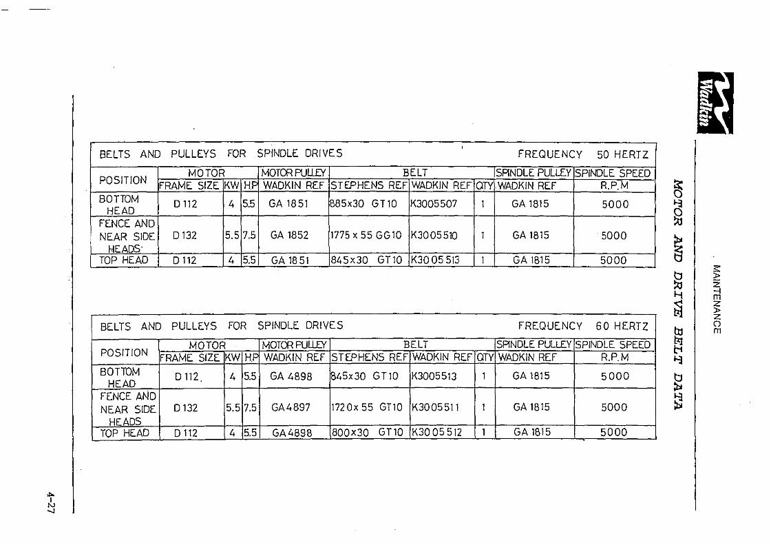
BELTS AND PULLEYS FOR
POSITION MOTOR
FRAME SIZE KW HJ BOTTOM D 112 4 5.5
HEAD FENCE AND NEAR SIDE D 132 5.5 7.5
HEADS· TOP HEAD D 112 4 5.5
BELTS AND PULLEYS FOR
MOTOR POSITION FRAME SIZE KW H.F BOTTOM D 112 4 5.5
HEAD FENCE AND NEAR SIDE D132 5.5 7.5
HEADS TOP HEAD D 112 4 5.5
.... i!, -.J
SPINDLE DRIVES '
MOTCfl PUU£Y BELT WADKIN REF STEPHENS REF WADKIN REF
GA 1851 B85x30 GT 10 K3005507
GA 1852 1775 x 55GG10 K3005510
GA 18 51 84Sx30 GT10 K30 05 513
SPINDLE DRIVES
MOTCfl PUU£Y BELT WADKIN REF STEPHENS REF WADKIN REF
GA 4898 B45x30 GT10 K3005513
GA4897 172 Ox 55 GT10 K3005511
GA4898 800x30 GT10 K3005512
QTY
1
1
1
OTY
1
1
1
FREQUENCY 50 HERTZ
SPINDLE PULLEY SPINDLE SPEED WADKIN REF R.P.M
GA 1815 5000
GA 1815 5000
GA 1815 5000
FREQUENCY 60 HERTZ
SPINDLE PULLEY SPINDLE SPEED WAOKIN REF R.P.M
GA 1815 5000
GA 1815 5000
GA 1815 5000
~ 11
~
~ ~ 1-j
~ ttJ ~ 11
~ ~
~ z --l m z )> z 0 m

ILLUSTRATED PARTS LIST
SECTION 5 ILLUSTRATED PARTS LIST
CONTENTS
1. Bedplates, Fences and Bedroll 2. lnfeed Table 3. lnfeed Fence 4. lnfeed Gate 5. Bottom Head Adjustment 6. Fence Side Head Adjustment 7. Near Side Head - Manual Adjustment 8. Near Side Head - Powered Adjustment 9. Near Side Head Hood 10. Side Head Belt Tensioning 11. Top Head Hood and Chipbreaker {180) 12 Top Head and Beam Vertical Adjustment - Manual 13. Top Head and Beam Vertical Adjustment - Powered 14. Rise and Fall Gearbox for Beam and Top Head 15. Spindle Assembly 16. Shaft Mounted Through Feed Rolls 17. Flange Mounted Through Feed Rolls 18. Outfeed Driven Bedroll 19. Top Head Hood and Chipbreaker (220) 20. Gearboxes and Drive Shafts (fixed speed) 21. Gearboxes and Drive Shafts (variable speed) 22. Drive to Outfeed Bedroll 23. Pneumatics
5-1
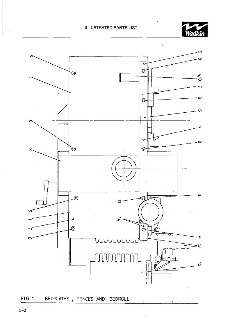
ILLUSTRATED PARTS LIST
())
@) w
N
FIG 1 BEDPLATES , FENCES AND BEDROLL
5-2
(£)
())
-::: 0
.._,
., @
C.11
JllbJ---0> 0 ' 1-"----~
--==w -+-----
I J]Z __ -N
:1

ILLUSTRATED PARTS LIST
1. BEDPLATES, FENCES AND BEDROLLS
Ref No.
1. 2.
or 3.
or 4.
or 5.
or 6. 7. 8. 9. 10. 11. 12. 13. 14.
Description
Bedplate after bottom head Near side head carriage with manual adjustment Near side head carriage with powered adjustment Outfeed bed plate with idle bedroll Outfeed bedpfate with driven bedroll Idle bedroll Driven bed roll (see separate section) Outfeed fence with idle bedroll Outfeed fence with driven bedroll Hexagon socket capscrew M12 x 25mm long Tension pin Smm dia x 40mm long Hexagon socket capscrew M12 x 60mm long Tension pin Smm dia x 24mm long Hexagon socket capscrew MS x 20mm long Tension pin Smm dia x SOmm long lnfeed table Fence between bottom head and fence side head Heavy duty tension pin 5mm dia x 24mm long
No Off.
1 1 6 3 4 1 2 1 1 1 2
5-3

Wadkln
------~IL=LU-ST-RA_T_ED_P_AR-Ts_u_sT--~--111
N N
-w
w
N N----,
FIG 2 INFEED TABLE
U1
())
'\ ~ \" -
~ 0

Wadkin
'I' ILLUSTRATED PARTS LIST
------2. INFEED TABLE
Ref No.
1. 2. 3. 4. 5. 6. 7. 8. 9. 10. 11. 12. 13. 14. 15. 16. 17. 1B. 19. 20. 21. 22. 23. 24.
Description
lnfeed table Lever for table heighl adjustmenl Locking handle Locking ring Adjustment scale Eccentric bush for infeed table Pivot pin for table Pivot pin for adjusting lever Lever block Positioning stud for table Spring Spring tension stud Pivot pin for table Pivot link for table Mounting bracket for adjusting lever Plain washer M 12 Hexagon nut M12 Hexagon socket capscrew MB x 30mm long Hexagon nut MB 'E' Retaining clip Bronze bush 0/0 30mm x 110 25mm x 25mm long Tolerance ring 25mm dia. x 20mm wide Taper washer M16 Hexagon nut M6
No Off.
1 1 1 1 1 2 1 1 1 1 1 1 1 2 1 3 3 1 2 4 4 2 1 1
5--5

Wadkln ILLUSTRATED PARTS LIST Ill
------
en -0
FIG 3 INFEEO FENCE
5--6
/1--11-----~
If.If--~
~ \ w 01 .r-.

Wadkln
'I' ILLUSTRATED PARTS LIST
------3. INFEED FENCE
Ref No.
1. 2. 3. 4. 5. 6. 7. 8. 9. 10. 11. 12. 13. 14.
Description
lnfeed fence Hand lever Fence pivot link Pivot link pin Pivot pin Washer Pointer bracket Scale Hexagon nut M12 Plain washer M 12 Drive screw Stud M 12 x 55mm long Hexagon socket capscrew MB x 12mm long Locking handle
No Off.
1 1 1 1 3 1 1 1 1 1 2 1 2 1
5-7

ILLUSTRATED PARTS LIST
2
6
7-------
1~
FIG 4 INFEED GATE
5-8
10
3

ILLUSTRATED PARTS LIST
4. INFEED GATE ASS EMBLY
Ref No.
1. 2. 3. 4. 5. 6. 7. 8. 9. 10.
Description
lnfeed gate Support plate for hinge Hexagon nut M6 Hexagon socket capscrew M4 x 16mm long Socket head button screw MS x 1 Smm long Tension pin M6 x 20mm long Hinge Limit switch Spring Plain washer M6
No Off.
1 3 2 3 2
1 3
5-9

Wadkln
ILLUSTRATED PARTS LIST Ill ------
(!) I
FIG 5 BOTTOM HEAD ADJUSTMENT .
5-10

Wadkin
'I' ILLUSTRATED PARTS LIST
------5. BOTTOM HEAD ADJUSTMENT
Rel No.
1. 2. 3. 4. 5. 6. 7. 8. 9. 10. 11.
Description
Worm shaft Barrel support bracket Clamping nut Spindle assembly Eccentric pin assembly Bronze headed bush 22mm O/D x 16mm l/D x 12mm long Stud M12 x 80mm long Hexagon setscrew M12 x 40mm long Taper washer M12 Bronze headed bush 18mm O/D x 12mm l/D x 20mm long Special locking nut M 12 x 1.0p
No Off.
1 1 1 1 1 1 1 4 4 1 2
5-ll

ILLUSTRATED PARTS LIST
3
FIG 6 FENCE SIDE HEAD ADJUSTMENT
5-12

Wadkln
'I' ILLUSTRATED PARTS LIST
------6. FENCE SIDE HEAD ADJUSTMENT
Ref No.
1. 2. 3. 4. 5. 6. 7. 8. 9. 10. 11.
Description
Worm shaft Barrel support bracket Clamping nut Spindle assembly Bronze headed bush 18mm O!D x 12mm l/D x 20mm long Special locking nut M12 x 1.0p Stud M12 x somm long Hexagon selscrew M12 x 40mm long Taper washer M12 Hexagon socket grubscrew M1 ox 25mm long Locknut M10
No Ott.
1 1 1 1 1 2 1 4 4 1 1
5-13

:O< ml> i::i ;o<
0,, "TJ:O :s:o )> :s: n :c z rn
ILLUSTRATED PARTS LIST
FIG 7 NEAR SIDE HEAD - MANUAL ADJUSTMENT
5-14

ILLUSTRATED PARTS LIST
7. NEAR SIDE HEAD-MANUAL ADJUSTMENT
Ref No.
1. 2. 3. 4. 5. 6. 7. s. 9. 10. 11. 12. 13. 14. 15.
Description
Leadscrew for adjustment Nut for lateral movement Bush 'INA' Thrust washer ref. AS2035 Collar 32mm O/D x 20mm f/D x 14mm Tension pin dia. 6mm x 32mm long Brass pad Stud MS x 45mm long Plastic hand wheel Nyloc hexagon socket screw MS x 16mm long Hexagon socket capscrew MS x SOmm long 'ELESA' axial retaining washer ref. GN31111 Hexagon socket countersunk screw M4 x 12mm long 'ELESA' crank handle ref. 44311 Near side head carriage
No Off.
1 2 2 2 1
1 1 3 1 1
5-15

.. ILLUSTRATED PARTS LIST
~
°''--
~
~---
\
FIG 8 NEAR SIDE HEAD- POWERED ADJUSTMENT
5-16
(J)
I ~
0~°' ~N
N w
~
1---..1
~ ~--N

ILLUSTRATED PARTS LIST
8. NEAR SIDE HEAD-POWERED ADJUSTMENT
Ref No.
1. 2. 3. 4. 5. 6. 7. 8. 9. 10. 11. 12. 13. 14. 15. 16. 17. 18. 19. 20. 21. 22. 23. 24. 25. 26. 27.
Description
Near side head carriage Leadscrew extension Limit activator support bar Nut for lateral movement Lead screw Extension for carriage Barrel support bracket (fence side head) Bush for carriage Gearbox mounting flange Worm geared motor unit Limit switch "Siko' dial indicator Hexagon socket capscrew MB x 50mm long Tension pin 6mm dia x 32mm long Key 5mm x 5mm x 32mm fang Hexagon socket grubscrew M6 x Bmm long Hexagon head setscrew M6 x 16mm long Bronze bush 25mm O/D x 20mm l/D x 25mm long Taper washer M12 Hexagon head setscrew M 12 x 30mm long 'INA' Thrust bearing ref. AXK 2035 '!NA' locating washer ref. WS 81104 'INA' Thrust washer ref. AS 2035 Locknuts M20 x 1.Sp Collar 20mm l/D Hexagon socket grubscrew M6 x 6mm long Hexagon socket grubscrew M6 x 25mm long
No Off.
1 3 1 1 1 8 1 2 2 2 2 2 2 3 2
5-17

ILLUSTRATED PARTS LIST Ip:; p 3iir ~~~~~~~~~~~~~~~~~- i~:MI
1 8 7
9-------~ \ ~/ 10----r~
....,....,, --.,,--
" 11----
'" 12 23--24
4
FIG 9 NEAR SIDE HEAD HOOD
5-18

ILLUSTRATED PARTS LIST
9. NEAR SIDE HEAD HOOD
Ref No.
1 . 2. 3. 4. 5. 6. 7. 8. 9. 10. 11. 12. 13. 14. 15. 16. 17. 18. 19. 20. 21. 22. 23. 24.
Description
lid for near side head hood Pressure support p1a1e Block for tension spring Pressure pad Screwed bar Exhuast hood Chamfered washer MB Wing nut MB Self locking nut M 16 Plain washer M 16 Siud M16 x 110mm long Bronze bush 20mm O/D x 16mm l/D x 16mm long Stud M 1 o x 40mm long Lock nutM10 Plain washer M 1 O Self locking nut MB Self locking nut M 10 Slud M10 x 60mm long Lock nu! MB Spring Hexagon socket capscrew M10 x 25mm long Plain collar dia. 10mm Hexagon socket countersunk screw M6 x 16 Chipbreaker shoe
No Off.
1 1 2 2
1 2
1 3 1 2 2 2
5-19

Wadkln ILLUSTRATED PARTS LIST Ill
------
18, 1 9 4 11, 17
16
6
14
FIG 10 SIDE HEAD BELT TENSIONING
5-20
w 90 "' < w ~ :i:
'11'
'
~10 w ;S U<:l: z w "-
~~~----7 ~------8
------3 ~-------9

Wadkln
'II ILLUSTRATED PARTS LIST
------10. SIDE HEAD BELT TENSIONING
Ref No.
1. 2. 3. 4. 5. 6. 7. 8. 9. 10. 11. 12. 13. 14. 15. 16. 17. 18. 19.
Description
Pivoting link for idle roller Idle roller support shaft Idle roller Fixing block for gas spring Pivot pin for idle roller link Tensioner pivot bracket External circlip dia. 25mm Bearing 'SFK' ref 6305 2RS Bearing 'SFK' rel 6206 2RS Stud MB x 35mm long Sett locking nut MB Hexagon socket countersunk screw MB x 25mm long Hexagon socket grubscrew MB x 35mm long Locknut MB Gas spring Bronze bush O/D 25mm x l/D 20mm x 15mm long Hexagon socket capscrew MB x 45mm long Large plain washer M 16 Hexagon head setscrew M16 x 35mm long
No Off.
1 1 1 1 1 1 1 1 1 1 2 5 1 1 1 1 1 1 1
5-21

Wad kin ILLUSTRATED PARTS LIST Ill
------
<5-~ :::-®
e----(J) £) @
FIG 11 TOP HEAD HOOD AND CHIPBREAKER -180
5-22

Wad kin
'I' ILLUSTRATED PARTS LIST
------11. TOP HEAD HOOD AND CHIPBREAKER - FSP180
Ref No.
1. 2. 3. 4. 5. 6. 7. s. 9. 10. 11. 12. 13. 14. 15.
Description
Top head/beam slide Top head hood Front cover Washer Bearing bush Coil spring Pivot shaft Top head pressure Hexagon socket capscrew MS x 12mm long Hexagon head setscrew M12 x 25mm long Plain washer M12 Tension pin dia. 6mm x 40mm long Hexagon socket capscrew M12 x 25mm long Hexagon head setscrew MB x 45mm long Lock nut MS
No Off.
1 1 1 1 2 1 1 1 2 2 2 1 1 1 1
5-23

Wad kin
ILLUSTRATED PARTS LIST Ill ------
N
I
I
FIG 12 TOP HEAD AND BEAM VERTICAL ADJUSTMENT - MANUAL
5-24

Wadkln
~~~~~~~~~1-LL_u_s_T_R_AT_E_D~PA_R_T_s_L_is_T~~~~~~~~~~~-12. TOP HEAD AND BEAM VERTICAL ADJUSTMENT-MANUAL
Ref No. Description No Off
1. Adjusting shaft bearing bracket 1 2. Adjusting shaft 1 3. Top head/beam slide 1 4. Rise and fall nut 1 5. Washer for rise and fall nut 1 6. Gearbox assembly 1 7. Bracket carrying cross shaft 1 8. Clamping block 1 9. Bronze bush 25mm O/D ~ 20mm l/D x 15mm long 2 10. 'Siko' digital counter 1 11. 'Elesa' crank handle 1 12. 'Elsea' axial retaining washer 1 13. Hexagon socket counter sunk screw M4 x 12mm long 1 14. Hexagon socket capscrew MB x 20mm long 2 15. Hexagon socket capscrew MB x 65mm long 2 16. Hexagon socket capscrew MB x 40mm long 2 17. Rise and fall leadscrew 1 1B. Bedplate
'
5-25

Wad kin ILLUSTRATED PARTS LIST Ill
------
i~® ® 6"" ,~ch ~
El
11
FIG .13 TOP HEAD AND BEAM VERTICAL ADJUSTMENT- POWERED
5-26
5
2,19
4
3, 15,21
18
22

Wadkln
'I' ILLUSTRATED PARTS LIST
------13. TOP HEAD AND BEAM VERTICAL ADJUSTMENT-POWERED
Ref No. Description No Off
1. Shaft bearing block 1 2. Universally jointed shaft 1 3. Beam support/head rise and fall nut 1 4. Lead screw 1 5. Beam/head slide support 1 6. Leadscrew support plate 1 7. Vertical position indicator shaft 1 8. Bronze bush 25mm O/D x 20mm l/D x 15mm long 2 9. Bronze bush 25mm O/D x 20mm VD x 20mm long. 2 10. Locknut M20 x 1.5p 2
11. 'INA' Thick thrust washer ref WS81104 2 12. 'INA' Thrust bearing ref AXK2035 2 13. 'INA' Thin thrust washer ref AS2035 2 14. Hexagon socket capscrew M 12 x 4Dmm long 3 15. Hexagon socket capscrew MB x 30mm long 2 16. Hexagon socket capscrew MB x 25mm long 2 17. Plain washer MB 2
18. Key 5m:n x 5mm x 25mm long 1 19. Hexagon socket grubscrew MS x 5mm long 2
20. "Siko' position indicator 0904 4mm pitch 1
21. Grease nipple 1 22. Worm geared motor unit 1
S--27

Wad kin ILLUSTRATED PARTS LIST Ill
------
/ {)1
- -Q) {)1 N
I
FIG 14 RISE AND FALL GEARBOX FOR BEAM AND TOP HEAD
5-28
~---0

Wadkln
'I' ILLUSTRATED PARTS LIST
------14. RISE AND FALL GEARBOX FOR BEAM AND TOP HEAD
Ref No.
1. 2. 3. 4. 5. 6. 7. 8. 9. 10. 11. 12. 13. 14. 15. 16. 17.
Description
Gearbox housing Collar Worm gear Worm wheel Adjusting shalt Rise and fall leadscrew 'SFK' bearing ref 6204 RS Internal circlip dia. 47mm Hexagon socket capscrew M12 x 30mm long Key 6mm x 6mm x 20mm long Hexagon socket grubscrew M6 x Bmm long Bronze bush 25mm O/D x 20mm l/D x 20mm long Key 6mm x 6mm x 40mm key 'INA' Thrust washer ref AS 2035 'INA' Thrust bearing ref AXK 2035 'INA' Thrust washerret WS 81104 Locknut M20 x 1.Sp
No Off.
1 1 1 1 1 1 2 2 3 2 2 1 1 3 2 1 2
5--29

Wadkln ILLUSTRATED PARTS UST Ill
------
Ul
FIG 15 SPINDLE ASSEMBLY
5-30

Wad kin
'I' ILLUSTRATED PARTS LIST
------15. SPINDLE ASSEMBLY
Ref No.
1. 2: 3. 4. 5. 6. 7.' 8. 9. 10. 11. 12. 13.
•NOTE:
Description
Flat belt spindle pulley Spindle barrel Nut for spindle barrel front bearing Nut for spindle front bearing Locking collar assembly Locking nut Spindle Bearing 'SFK' 6009 Bearing 'SFK' 6306 Pulley spigot Hexagon head setscrew M 12 x 40mm long Bearing disc springs Key 8mm x 7mm x 40mm long
Specify spindle position and machine capacity when ordering i.e. Top head· 180, Bottom head· 220, etc.
No Off.
1 1 1 1 1 1 1 1 1 1 1 6 1
5-31

ILLUSTRATED PARTS LIST
~l--~
FIG 16 SHAFT MOUNTED THROUGH FEED ROLL
5-32

ILLUSTRATED PARTS LIST
16. SHAFT MOUNTED THROUGH FEED ROLL
Ref No.
1. 2. 3. 4. 5. 6. 7. 8. 9. 10. 11. 12. 13. 14. 15.
16 .. 17.
NOTE:
Description
Swing for feed roll Feed roller (specify serrated steel or polyurethane) Shaft Pivot pin (for single unit) Pivot pin (for double unit) 'E' retainer Bearing "SFK' 6206 2RS Bearing 'SFK' 6305 2RS Key Smm x ?mm x 20mm long Key 10mm x Smm x 150mm long External circlip 30mm dia. Hexagon socket grubscrew MB x 25mm Jong Hexagon nut M6 Hexagon head setscrew M10 x 16mm long Special "Schrader' single acting cylinder IXB 4726C complete with fittings Bronze bush 25mm O/D x 20mm l/D x 20mm long Internal circlip dia. 62mm
Illustration shows the trailing shalt mounted feed roll. When a leading feedroll unit is used item 1 is lilted in the opposite manner with it's front fork preceding the trailing swing Iron! fork.
No 011.
1 2 1 1
2
5-33

ILLUSTRATED PARTS LIST
I
w
(]1
FIG 17 FLANGE MOUNTED THROUGH FEED ROLL
5-34

ILLUSTRATED PARTS LIST
17. FLANGE MOUNTED THROUGH FEED ROLL
Ref No.
1. 2. 3. 4. 5.
6. 7. 8.
9. 10. 11. 12. 13. 14. 15.
16. 17.
NOTE:
Description No Off.
Swing for feed roll 1 ·c· Washer 1 Feed roll, complete with location peg 2 Spacer Shaft assembly (includes M12 helical insert and M12 x 100mm long setscrew) Pivot pin for swing Feed roll mounting flange Spacer. complete with location peg (used w.Mn second feedroll required) 1 'E' Retainer 2 Bearing 'SFK' 6206 2RS 2 Key Bmm x ?mm x 20mm long External circlip 30mm dia. Hexagon socket grubscrew MB x 25mm long 1 Hexagon nut MB 1 Special 'Schrader' single acting cylinder tXB 4726C complete ~hlitti~ 1 Bronze bush 25mm O!D x 20mm l/D x 20mm long 2 lnlernal circlip dia. 62mm 1
lllustralion shows the trailing llange mounted feed roll. On the leading feedroll, items 1 and 6 are fitted the opposite way around to that shown. Ouantilies quoted are per complete unit.
5-35

ILLUSTRATED PARTS LIST
------20
-~- 8
6 2
FIG 18 DRIVEN OUTFEED BEDROLLER
5-36

ILLUSTRATED PARTS LIST
18. DRIVEN OUTFEED BEDROLL
Ref.
1. 2. 3. 4. 5. 6. 7. 8. 9 .• 10. 11. 12. 13. 14. 15. 16. 17. 18. 19. 20. 21.
Description
Pivot pin for swing Polyurethane feedroll Bottom roller swing Spring support block Cap for spring Shatt for roller Outleed bed plate Fence after fence side head Cover for outfeed bedroll Nut M12 Plain washer M 12 Locknut M12 Terry' Compression spring ref D13810 Bronze headed bush Key 8mm x ?mm x 20mm long Key 10mm x Bmm x 40mm long Hexagon socket grubscrew M10 x 10mm long Bronze bush 25mm O/D x 20mm llD x 20mm long External circlip 20mm dia Hexagon head setscrew M12 x 80mm long Stud M 12 x 105mm long
• Not illustrated
No Off.
1 1 1 1 1 1
1 3 1 2 1 1 1 2 2
5-37

Wad kin ILLUSTRATED PARTS LIST Ill
------
U1
FIG 19 TOP HEAD HOOD AND CHIPBREAKER (220)
5-38

Wadkln
'I' ILLUSTRATED PARTS LIST
------19. TOP HEAD HOOD AND CHIPBREAKER - FSP220
Ref No.
1. 2. 3. 4. 5. 6. 7. B. 9. 10. 11. 12. 13. 14. 15. 16. 17. 18. + 19. +
Description
Top head/beam slide Top head hood Front cover Washer Rear bearing bush Coil spring Pivot shaft Top head pressure Chipbreaker shoe Front bearing bush Hexagon socket capscrew MB x 12mm long Hexagon head setscrew M12 x 25mm long Plain washer M 12 Tension pin dia. 6mm x 40mm long Hexagon head selscrew MB x 45mm long Lock nut Ma Hexagon socket capscrew M 12 x 25mm long Hexagon socket countersunk screw M6 x 16mm long 'Helicoil" insert M6
+ Not illustrated
No Off.
1 1 1 1 1 1 1 1 1 1 2 2 2 1 1 1 1 3 3
5-39

ILLUSTRATED PARTS LIST
11 ~----r 0
- -1-- ,_-I - - ~-11-+1+- -E9- EE3-
'\/ 10
~/ 10 1 10 2
4,6 0
3
FIG 20 GEARBOXES AND DRIVE SHAFTS (SINGLE SPEED)
5-40

ILLUSTRATED PARTS LIST
20. GEARBOXES AND DRIVE SHAFTS {FIXED SPEED)
Ref.
1. 2. 3. 4. 5. 6. 7. 8. 9. 10. 11. 12.
Description
Single gearbox MI 50 {10 :1) Connecting rod Gearbox and motor assembly 'Rotex' coupling ref 19ALUD Adaptor 'Rotex' coupling spider 'Elbe' universal shaft Feed roll swing Key Bmm x 7mm x 40mm long {gearbox drive) Star fastner for universal shaft Hexagon socket grubscrew MS x Bmm long Key Bmm x7mm x 20mm long (feedroll shaft drive)
No Off.
1 2 3 2 5 5 5 5
10 5
5-41

ILLUSTRATED PARTS LIST
c
-.J?:Ja..L--15-----=~ • 12,13,14
12,13,14---/
17 17 5,6
8,9 10,11 2
4
FIG 21 GEARBOXES ANO DRIVE SHAFTS ( VARIABLE SPEED)
5--42

ILLUSTRATED PARTS LIST
21. GEARBOXES AND DRIVE SHAFTS (VARIABLE SPEED)
Ref.
1. 2. 3. 4. 5. 6. 7. 8. 9. 10. 11. 12. 13. 14. 15. 16. 17.
Description
Gearbox and motor assembly Single gearbox Ml 50 (10:1) Connecting rod Handwheel and dial 'Rotex' coupling ref 19ALUD 'Rotex' coupling spider Adaptor Pointer bracket Mounting bracket for speed control Universal joint Hexagon socket grubscrew M6 x 6mm long 'Elbe' universal shaft Key Bmm x ?mm x 40mm long (gearbox drive) Key Bmm x ?mm x 20mm long (feedroll shaft drive) Hexagon socket grubscrew M6 x 8mm long Feed roll swing Star fastner for universal shaft
No Off.
2 2 3 1 1 1 2 5 5 5
10 5 5
5-43

ILLUSTRATED PARTS LIST
9
11
2
FIG 22 DRIVE TO OUTFEEO BEDROLL

ILLUSTRATED PARTS LIST
22. DRIVE TO OUTFEED BEDROLL
Ref.
1. 2. 3. 4. 5. 6. 7. 8. 9. 10. 11. 12. 13.
..
Description
Single gearbox MISO (10:1) Universal drive shaft Gearbox support bracket Beam Top feed roll gearbox 'Fenner' timing pulley ref 27L075 'Fenner' timing belt ref 187L075 Taper lock bush 14mm bore ref 1108 Star lock fastner Key 8mm x 7mm x 40mm long Hexagon socket capscrew M6 x 12mm long Hexagon socket capscrew MG x 16mm long Key Smm x Smm x 20mm long
_No Off.
1 2 1 2
4 4 2
5-45

ILLUSTRATED PARTS LIST
/' ____ ;
~2
3-6 bar (J.2-67 P.5.1)
-----5 FEEOROLL BEFORE BOTTOM HEAD
FiG 23 PNEUMATICS
5-46
FEEDROLL BETWEEN SIDE HEADS
FEEDROLL AFTER TOP HEAD
FEEDROLL AFTER BOTTOM HEAD
FEEOROLL BEFORE TOP HEAD

ILLUSTRATED PARTS LIST
23. PNEUMATICS
Ref.
1. 2. 3 .• 4 .• 5.
Description
'Norgan' Pressure regulator ref ROS-200-RNKD . Pressure gauge
'Schreder' 3/2 spool valve ref 843003-1 OOA 'Schrader' facia actuator ref 33000-1 OOOUAXS 'Schrader' single acting cylinder ref IXB 4726C
No Off.
1 1 5
Items 3. and 4. are only fitted when individual air control is present for the feedrolt.
5-47

::i :1 '.3
~ 1C8 1ML 1U ,..., t-1 t-1---~~I :~:@ BOTIOM HEAD
....-!--.. 2CB 2ML 2U
H-t----~~1 2v'.f2\ FENCE/NEAR SIDE i----~~~ I· 2W~T~ HEAD
....!-., JCS 3 ML 3 U .... , ,_11,__--~~I ~~E@
Wl'ldkin
ODO LEICESTER
WOODWORKING DIVISION
Dote S!u,
TO? HEAD
CI Doto Si"I. B
20.3 900 200
STOP START
t---<LLo--1!,!1_...;;_L 12 1::.--_t~-11::.._ ____________ __,~~
,-,
1ML 14 -.+-1----j
BRAKE COIL
STOP START
1----<>--'-'>--'21'1---o_i_ 2 2 r2:. ........ • I ~ ~r 'o~
/ '
BOTTOM HEAD INDICATOR LIGHT
BRAKE 'OFF'
FENCE/NEAR HEAD· INDICATOR LIGHT
2ML 24 ~I I BRAKE 'OFF'
BRAKE COIL
STCI' START
f----o...Lo--'3f1--¢_L0----''~2'-----------------{ 3 ML
TOP HEAD INDICATOR LIGHT
3ML 34 -.i- BRAKE 'OFF' 1-1---,--;: BRAKE COIL
Dote SI Description
D663 A CE Dron K.MOBBS
FS p SPEC ;;:·•.PATEL -Or'owlng No.
CAD Locptk>n W,0, No 12/11 /94 N: \ACAD\D~\l;LECTDO\ELECSTD\ESTD0629 SHEET 02

---~--··------A·~-·-·--•••• •••,,