liebert dm chilled water series - vertiv · 5.1 lcd screen ... liebert_dm chilled water series air...
TRANSCRIPT

Technical ManualLiebert® DM Chilled Water Series
Precision CoolingFor Business-Critical Continuity™
Liebert_DM Chilled Water Series Cooling Unit
Technical Manual
Version V1.0
Revision date 2010.12.10
BOM 31020817
Emerson Network Power provides customers with technical support. Users may contact
the nearest Emerson local sales office or service center.
Copyright © 2010 by Emerson Network Power Co., Ltd..
All rights reserved. The contents in this document are subject to change without notice.
Emerson Network Power Co., Ltd.
Address: No.1 Kefa Rd., Science & Industry Park, Nanshan District 518057, Shenzhen
China
Homepage: www.emersonnetworkpower.com.cn
E-mail: [email protected]

Contents
THE Liebert_DM ENVIRONMENTAL CONTROL SYSTEM ..................................................................... 3
Chapter 1 Features and Benefits ............................................................................................................ 1
Chapter 2 Model Configuration ............................................................................................................... 3
2.1 Model Number Designations ...................................................................................................... 3
2.2 Unit Mechanical Parameters ....................................................................................................... 3
Chapter 3 Operation Range ................................................................................................................... 5
Chapter 4 Technical Data ....................................................................................................................... 6
Chapter 5 Microprocessor Control .......................................................................................................... 7
5.1 LCD Screen ............................................................................................................................. 7
5.2 Control Buttons ........................................................................................................................ 7
5.3 Setpoints .................................................................................................................................. 8
5.4 Control Screen ......................................................................................................................... 9
5.4.1 Off Screen ..................................................................................................................... 9
5.4.2 On Screen ..................................................................................................................... 9
5.4.3 Normal Screen .............................................................................................................. 9
5.4.4 Password Screen .......................................................................................................... 9
5.5 Main Menu ............................................................................................................................. 10
5.6 Alarm Menu ............................................................................................................................ 10
5.6.1 Alarm Status ............................................................................................................... 10
5.6.2 Alarm History .............................................................................................................. 11
5.6.3 Alarm Setpoint ............................................................................................................ 11
5.6.4 Alarm Output ............................................................................................................... 11
5.6.5 Custom Alarm ............................................................................................................. 12
5.6.6 Service Interval ........................................................................................................... 12
5.7 Setpoints ................................................................................................................................ 13
5.8 System Status ........................................................................................................................ 13
5.8.1 Tem/ Hum ................................................................................................................... 13
5.8.2 Time/Date ................................................................................................................... 13
5.8.3 Output Status .............................................................................................................. 13
5.8.4 Run Time .................................................................................................................... 14
5.8.5 Comp Run Record ...................................................................................................... 14
5.9 System Menu ......................................................................................................................... 14
5.9.1 Setup System ............................................................................................................. 14
5.9.2 Select Options ............................................................................................................ 15
5.9.3 Sensor Calibrate ......................................................................................................... 16
5.9.4 Diagnose..................................................................................................................... 16
5.9.5 Change Password ...................................................................................................... 16
5.9.6 Factory Reset ............................................................................................................. 17
5.10 Help Menu ............................................................................................................................ 17
5.10.1 Normal Info ............................................................................................................... 17
5.10.2 Service Info ............................................................................................................... 18
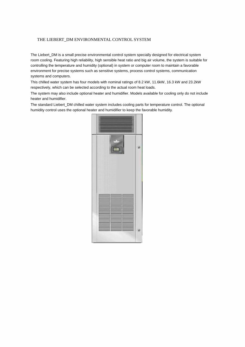
THE LIEBERT_DM ENVIRONMENTAL CONTROL SYSTEM
The Liebert_DM is a small precise environmental control system specially designed for electrical system
room cooling. Featuring high reliability, high sensible heat ratio and big air volume, the system is suitable for
controlling the temperature and humidity (optional) in system or computer room to maintain a favorable
environment for precise systems such as sensitive systems, process control systems, communication
systems and computers.
This chilled water system has four models with nominal ratings of 8.2 kW, 11.6kW, 16.3 kW and 23.2kW
respectively, which can be selected according to the actual room heat loads.
The system may also include optional heater and humidifier. Models available for cooling only do not include
heater and humidifier.
The standard Liebert_DM chilled water system includes cooling parts for temperature control. The optional
humidity control uses the optional heater and humidifier to keep the favorable humidity.

Chapter 1 Features and Benefits 1
Liebert_DM Chilled water Series Air Conditioner Technical Manual
Chapter 1 Features and Benefits
Computer Matched-Liebert systems are designed to create the environment required for computers, telecom
and other sensitive electronic equipment. Liebert_DM provides complete control of temperature, humidity and air
cleanliness on an around the clock basis, as well as the high sensible heat ratio required by sensitive electronic
equipment. Space Saving-Requires 5 square feet (.5m2
) or less.
Reliable-The Liebert reputation for quality and a nationwide service network ensures maximum uptime.
Designed to Fit-Models available to fit any room without disrupting work-station layout.
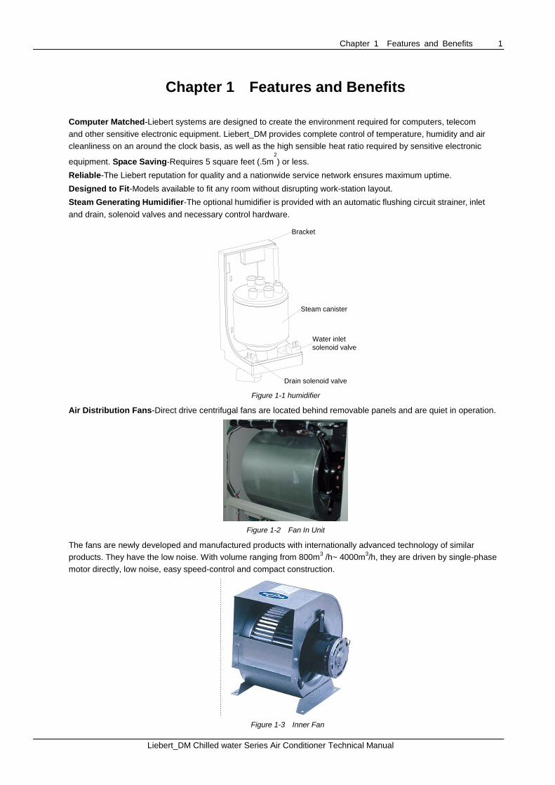
Steam Generating Humidifier-The optional humidifier is provided with an automatic flushing circuit strainer, inlet
and drain, solenoid valves and necessary control hardware.
Water inlet
solenoid valve
Drain solenoid valve
Steam canister
Bracket
Figure 1-1 humidifier
Air Distribution Fans-Direct drive centrifugal fans are located behind removable panels and are quiet in operation.
Figure 1-2 Fan In Unit
The fans are newly developed and manufactured products with internationally advanced technology of similar
products. They have the low noise. With volume ranging from 800m3 /h~ 4000m
3/h, they are driven by single-phase
motor directly, low noise, easy speed-control and compact construction.
Figure 1-3 Inner Fan

2 Chapter 1 Features and Benefits
Liebert_DM Chilled water Series Air Conditioner Technical Manual
Intelligent Microprocessor Control- The system controller has a 128×64-matrix dot LCD screen with blue
backlight. The man-machine-interface is easy-to-use. Multilevel passwords are configured to prevent unauthorized
operation. The program is stored in non-volatile memory. The controller also has functions of high-voltage/low-voltage
protection, phase failure protection and phase switchover in case of reverse phase rotation. Users can acquire the
accurate running time of major parts by browsing the menu. Expert-level troubleshooting system enables the LCD to
display the fault information automatically for convenient maintenance. The controller can store up to 30 history alarms.
It can communicate to a host through the RS485 port.
Figure 1-4 Control Panel
Easy Installation-All components of the Liebert_DM are pre-charged and require no field brazing, evaluation or
charging. Pre-charged refrigerant lines are available in 15-foot and 30-foot lengths (4.5 and 9m) to connect evaporator
and condensing unit modules.
Serviceability-The Liebert_DM is designed with front service access. Routine maintenance and service can be
performed quickly and easily.
Chapter 2 Model Configuration 3
Liebert_DM Chilled water Series Air Conditioner Technical Manual
Chapter 2 Model Configuration
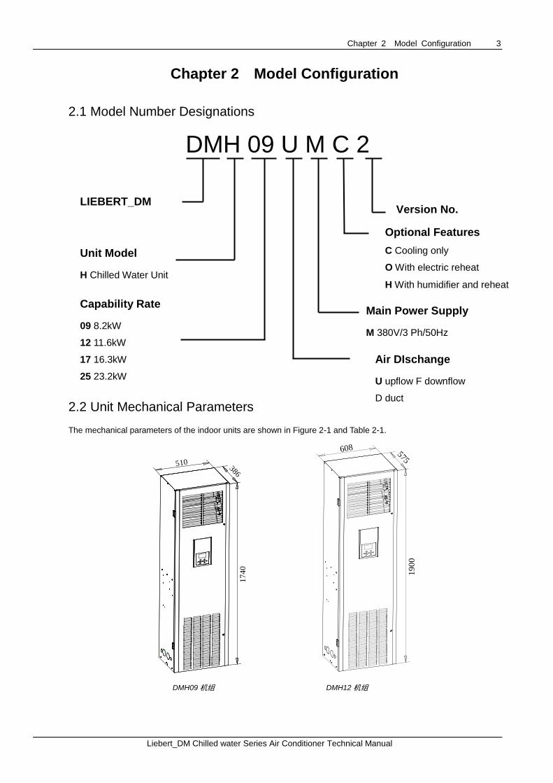
2.1 Model Number Designations
DMH 09 U M C 2
2.2 Unit Mechanical Parameters
The mechanical parameters of the indoor units are shown in Figure 2-1 and Table 2-1.
510
17
40
386
608
19
00
575
DMH09 机组 DMH12 机组
LIEBERT_DM
Air Conditioner
Unit Model
H Chilled Water Unit
Optional Features
C Cooling only
O With electric reheat
H With humidifier and reheat
Capability Rate
09 8.2kW
12 11.6kW
17 16.3kW
25 23.2kW
12 12kW
Main Power Supply
M 380V/3 Ph/50Hz
Version No.
Air DIschange
U upflow F downflow
D duct
4 Chapter 2 Model Configuration
Liebert_DM Chilled water Series Air Conditioner Technical Manual
17
40
1102 405
19
00
1202 575
DMH17 机组 DMH25 机组
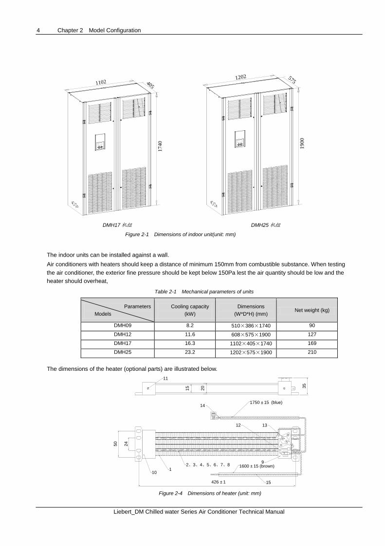
Figure 2-1 Dimensions of indoor unit(unit: mm)
The indoor units can be installed against a wall.
Air conditioners with heaters should keep a distance of minimum 150mm from combustible substance. When testing
the air conditioner, the exterior fine pressure should be kept below 150Pa lest the air quantity should be low and the
heater should overheat,
Table 2-1 Mechanical parameters of units
Parameters
Models
Cooling capacity
(kW)
Dimensions
(W*D*H) (mm) Net weight (kg)
DMH09 8.2 510×386×1740 90
DMH12 11.6 608×575×1900 127
DMH17 16.3 1102×405×1740 169
DMH25 23.2 1202×575×1900 210
The dimensions of the heater (optional parts) are illustrated below.
14
13
9
15426 ±1
35
20
15
11
50
24
1750 ±15 (blue)
1600 ±15 (brown)
12
2、3、4、5、6、7、81
10
Figure 2-4 Dimensions of heater (unit: mm)

Chapter 3 Operation Range 5
Liebert_DM Chilled water Series Air Conditioner Technical Manual
Chapter 3 Operation Range
Liebert_DM are provided for operating within the following working ranges:
Operating environment
The operating environment shall meet the standards of GB4798.3-90. For details, please refer to Table 1-1.
Table 3-1 Requirement of operating environment
Item Requirement
Installation Vertical installation, with the installation base ≥150mm
Ambient temperature Indoor temperature: 4ºC~40ºC
Chilled water inlet temperature: 5ºC~12ºC
altitude <1000m, derated when it is more than 1000m
Operating voltage range 3N~380V (-15%~+20%) , 50Hz 3N~
Storage conditions
The storage environment shall meet the standards of GB4798.3-1996. For details, please refer to Table 1-2.
Table 3-2 Requirement of storage environment
Item Requirement
Storage environment Indoor, clean (free of dust)
Ambient humidity 5%RH~85%RH5%RH~85%RH
Ambient temperature -20ºC~+54ºC
Storage time No more than 6 months in total (transportation plus storage), performance needs to be reevaluated after
6 months
Notes:
1) The system should be derated where the altitude is higher than 1000m;
2) The error (because of sensors) in 3% is permitted;
3) The shipment and storage time should not exceed 6 months. Otherwise, the system shall be re-tested.
6 Chapter 4 Technical Data
Liebert_DM Chilled water Series Air Conditioner Technical Manual
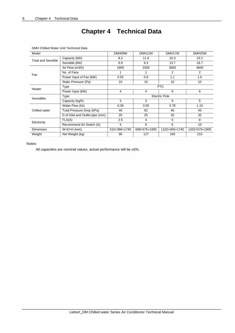
Chapter 4 Technical Data
Notes:
All capacities are nominal values, actual performance will be ±5%.
DMH Chilled Water Unit Technical Data
Model DMH09M DMH12M DMH17M DMH25M
Total and Sensible Capacity (kW) 8.2 11.6 16.3 23.2
Sensible (kW) 6.9 9.3 13.7 18.7
Fan
Air Flow (m3/h) 1800 2300 3600 4600
No. of Fans 1 1 2 2
Power Input of Fan (kW) 0.55 0.8 1.1 1.6
Static Pressure (Pa) 10 10 10 10
Heater Type PTC
Power Input (kW) 4 4 6 6
Humidifier Type Electric Pole
Capacity (kg/h) 3 3 5 5
Chilled water
Water Flow (l/s) 0.39 0.55 0.78 1.10
Total Pressure Drop (kPa) 46 62 46 45
D of Inlet and Outlet pipe (mm) 25 25 32 32
Electricity FLA(A) 2.5 4 5 8
Recommend Air Switch (A) 4 6 6 10
Dimension W×D×H (mm) 510×386×1740 608×575×1900 1102×405×1740 1202×575×1900
Weight Net Weight (kg) 90 127 169 210
Chapter 5 Microprocessor Control 7
Liebert_DM Chilled water Series Air Conditioner Technical Manual
Chapter 5 Microprocessor Control
The microprocessor control features an easy-to-use menu-driven LCD display. It monitors and displays the operation
status of the precision cooling unit to maintain a reasonable environment in the controlled room. The menus, control
features and parameter settings are described in this chapter.
Note
Because the Liebert_DM Air cooling and chilled water series units share the same model of microprocessor, the contents related to the compressor control are applicable to the Air cooling series unit only.
5.1 LCD Screen
LCD screen displays English menus with blue backlight. It displays temperature and relative humidity readings,
operating mode (cool, heat, dehumidify, humidify), alarm information, current date and time, as shown in Figure 5-1.
2 8 ℃ C o o l
5 0 % r h H u m
H i g h T e m p 1 / 4
2 0 0 4 / 0 1 / 0 1 0 0 : 0 0
Figure 5-1 LCD screen
Users can browse more detailed information such as the operation status of a certain part and alarm information by
activating the sub-menus in the main menu screen. The selected item will highlight in a menu. The digit to be changed
will highlight when a parameter is being changed.
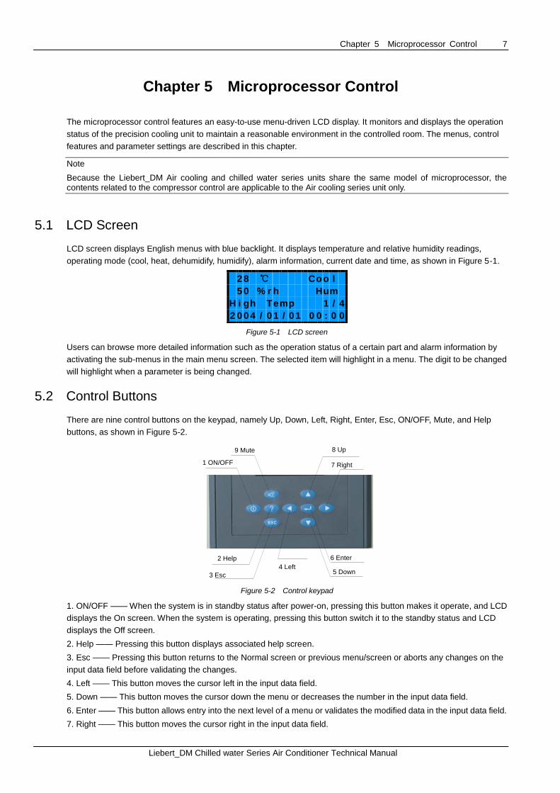
5.2 Control Buttons
There are nine control buttons on the keypad, namely Up, Down, Left, Right, Enter, Esc, ON/OFF, Mute, and Help
buttons, as shown in Figure 5-2.
5 Down
9 Mute
1 ON/OFF
2 Help
3 Esc
4 Left
6 Enter
7 Right
8 Up
Figure 5-2 Control keypad
1. ON/OFF —— When the system is in standby status after power-on, pressing this button makes it operate, and LCD
displays the On screen. When the system is operating, pressing this button switch it to the standby status and LCD
displays the Off screen.
2. Help —— Pressing this button displays associated help screen.
3. Esc —— Pressing this button returns to the Normal screen or previous menu/screen or aborts any changes on the
input data field before validating the changes.
4. Left —— This button moves the cursor left in the input data field.
5. Down —— This button moves the cursor down the menu or decreases the number in the input data field.
6. Enter —— This button allows entry into the next level of a menu or validates the modified data in the input data field.
7. Right —— This button moves the cursor right in the input data field.
8 Chapter 5 Microprocessor Control
Liebert_DM Chilled water Series Air Conditioner Technical Manual
8. Up —— This button moves the cursor up on the menu or increases the value displayed in the input data field.
9. Mute —— If an alarm is present, it will be displayed on the LCD and sound an audible beeper. Pressing this button
eliminates the prompted alarm screen and silences the alarm.
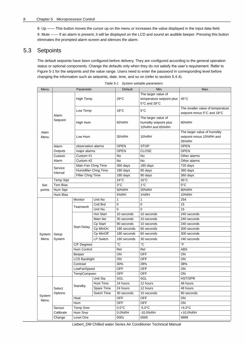
5.3 Setpoints
The default setpoints have been configured before delivery. They are configured according to the general operation
status or optional components. Change the defaults only when they do not satisfy the user’s requirement. Refer to
Figure 5-1 for the setpoints and the value range. Users need to enter the password in corresponding level before
changing the information such as setpoints, date, time, and so on (refer to section 5.4.4).
Table 5-1 System settable parameters
Menu Parameter Default Min. Max.
Alam
Menu
Alarm
Setpoint
High Temp 29°C The larger value of
temperature setpoint plus
5°C and 28°C 45°C
Low Temp 18°C 5°C The smaller value of temperature
setpoint minus 5°C and 18°C
High Hum 65%RH
The larger value of
humidity setpoint plus
10%RH and 65%RH
90%RH
Low Hum 35%RH 10%RH
The larger value of humidity
setpoint minus 10%RH and
35%RH
Alarm
Outputs
observation alarms OPEN STOP OPEN
major alarms OPEN CLOSE OPEN
Custom
Alarm
Custom #1 No No Other alarms
Custom #2 No No Other alarms
Service
Interval
Main Fan Chng Time 360 days 180 days 720 days
Humidifier Chng Time 180 days 90 days 360 days Filter Chng Time 180 days 90 days 360 days
Set-
points
Temp Stpt 24°C 15°C 35°C Tem Bias 3°C 1°C 5°C Hum Stpt 50%RH 20%RH 80%RH Hum Bias 5%RH 1%RH 10%RH
System
Menu
Setup
System
Monitor Unit No 1 1 254
Teamwork Cntl Brd 0 0 15 Unit No. 0 0 15
Start Delay
Hot Start 10 seconds 10 seconds 240 seconds Main fan 30 seconds 10 seconds 240 seconds
Cp Start 90 seconds 10 seconds 240 seconds
Cp MinOn 180 seconds 60 seconds 300 seconds
Cp MinOff 180 seconds 60 seconds 300 seconds
LP Switch 180 seconds 30 seconds 240 seconds
C/F Degrees °C °C °F
Hum Control Rel Rel ABS
Beeper ON OFF ON
LCD Backlight ON OFF ON
Contrast 30% 28% 38% LowFanSpeed OFF OFF ON
TempCompsen OFF OFF ON
System
Menu
Select
Options
Standby
Unit Sta SGL SGL HST/SPR
Host Time 24 hours 12 hours 48 hours Spare Time 24 hours 12 hours 48 hours Swtch Time 30 seconds 10 seconds 90 seconds
Heat OFF OFF ON
Hum OFF OFF ON
Sensor
Calibrate
Temp Snsr 0.0°C -5.0°C +5.0°C Hum Snsr 0.0%RH -10.0%RH +10.0%RH
Change Level One 0001 0000 9999

Chapter 5 Microprocessor Control 9
Liebert_DM Chilled water Series Air Conditioner Technical Manual
Menu Parameter Default Min. Max.
Password Level Two 0002 0000 9999
5.4 Control Screen
5.4.1 Off Screen
The LCD displays this screen after the system is powered on. In addition, it will be displayed by pressing the ON/OFF
button during system operation, as shown in Figure 5-3. You can press the Left/Right button and the Enter button to
select the display language.
E M E R S O N E n g l i s h 中 文
Figure 5-3 Off screen
5.4.2 On Screen
When the system is in automatic turn-on status after powered on, the LCD displays the On screen. Press the ON/OFF
button from the Off screen, and the On screen will also be displayed, as shown in Figure 5-4.
S t a r t i n g
1 0 s
Figure 5-4 On screen
5.4.3 Normal Screen
After the system is powered on, the Normal screen will be displayed after 10 seconds (default) for heat startup delay or
after Enter button is pressed. The Normal screen displays the current temperature and relative humidity readings,
operating mode (cool, heat, dehumidify, humidify), alarm information, current date and time, as shown in Figure 5-5.
2 8 ℃ C o o l
5 0 % r h H u m
H i g h T e m p 1 / 4
2 0 0 4 / 0 1 / 0 1 0 0 : 0 0
Figure 5-5 Normal screen
5.4.4 Password Screen
There are three levels of password in the microprocessor control.
Level one password (0001) is intended for the ordinary user. Users can view all menus by entering this password, but
has no authority to change the parameters except for those of temperature and humidity.
Level two password is intended for trained service personnel. Users can change all parameters by entering this
password.
Level three password is intended for the manufacturer’s personnel only.
Press Enter button from the Normal screen, Password screen is displayed, as shown in Figure 5-6.
P a s s w o r d : 1 * * *
Figure 5-6 Password screen
Method of entering password:
10 Chapter 5 Microprocessor Control
Liebert_DM Chilled water Series Air Conditioner Technical Manual
Press Left/Right button to move the cursor to the digit to be changed, and then Up/Down button to change the value.
Press Enter button to validate the password and enter the main menu. Press Esc button to return to the Normal
screen.
If the password entered is incorrect, the user can view the menu but cannot change the parameters. The user can
return to the Normal screen by pressing Esc button and enter the password again. If the password entered is correct,
any parameter under the main menu can be changed.
Note
If press Enter button from the Password screen instead of inputting any password, the user can only view the menu and cannot
change the parameters.
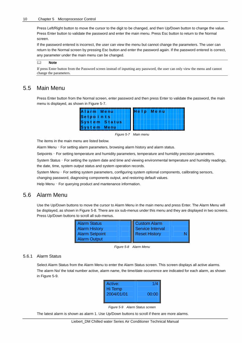
5.5 Main Menu
Press Enter button from the Normal screen, enter password and then press Enter to validate the password, the main
menu is displayed, as shown in Figure 5-7.
A l a r m M e n u
S e t p o i n t s
S y s t e m S t a t u s
S y s t e m M e n u
H e l p M e n u
Figure 5-7 Main menu
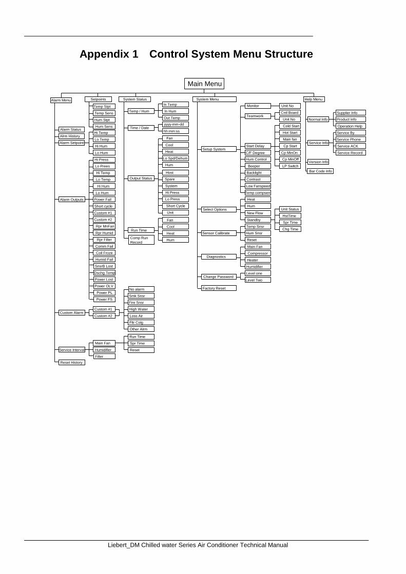
The items in the main menu are listed below.
Alarm Menu - For setting alarm parameters, browsing alarm history and alarm status.
Setpoints - For setting temperature and humidity parameters, temperature and humidity precision parameters.
System Status - For setting the system date and time and viewing environmental temperature and humidity readings,
the date, time, system output status and system operation records.
System Menu - For setting system parameters, configuring system optional components, calibrating sensors,
changing password, diagnosing components output, and restoring default values.
Help Menu - For querying product and mantenance information.
5.6 Alarm Menu
Use the Up/Down buttons to move the cursor to Alarm Menu in the main menu and press Enter. The Alarm Menu will
be displayed, as shown in Figure 5-8. There are six sub-menus under this menu and they are displayed in two screens.
Press Up/Down buttons to scroll all sub-menus.
Alarm Status
Alarm History
Alarm Setpoint
Alarm Output
Custom Alarm
Service Interval
Reset History
N
Figure 5-8 Alarm Menu
5.6.1 Alarm Status
Select Alarm Status from the Alarm Menu to enter the Alarm Status screen. This screen displays all active alarms.
The alarm No/ the total number active, alarm name, the time/date occurrence are indicated for each alarm, as shown
in Figure 5-9.
Active:
Hi Temp
2004/01/01
1/4
00:00
Figure 5-9 Alarm Status screen
The latest alarm is shown as alarm 1. Use Up/Down buttons to scroll if there are more alarms.
Chapter 5 Microprocessor Control 11
Liebert_DM Chilled water Series Air Conditioner Technical Manual
This system can store up to 25 latest active alarms. They will be lost when the system is powered off.
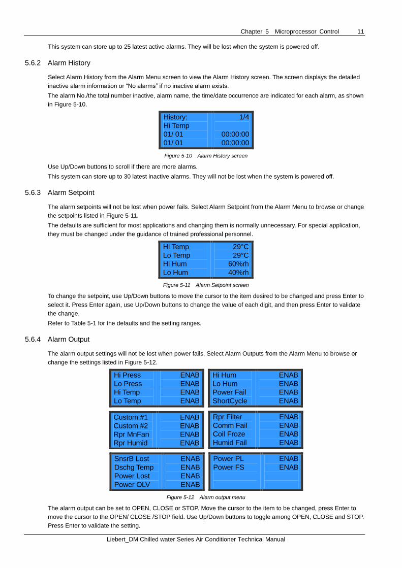
5.6.2 Alarm History
Select Alarm History from the Alarm Menu screen to view the Alarm History screen. The screen displays the detailed
inactive alarm information or “No alarms” if no inactive alarm exists.
The alarm No./the total number inactive, alarm name, the time/date occurrence are indicated for each alarm, as shown
in Figure 5-10.
History:
Hi Temp
01/ 01
01/ 01
1/4
00:00:00
00:00:00
Figure 5-10 Alarm History screen
Use Up/Down buttons to scroll if there are more alarms.
This system can store up to 30 latest inactive alarms. They will not be lost when the system is powered off.
5.6.3 Alarm Setpoint
The alarm setpoints will not be lost when power fails. Select Alarm Setpoint from the Alarm Menu to browse or change
the setpoints listed in Figure 5-11.
The defaults are sufficient for most applications and changing them is normally unnecessary. For special application,
they must be changed under the guidance of trained professional personnel.
Hi Temp
Lo Temp
Hi Hum
Lo Hum
29°C
29°C
60%rh
40%rh
Figure 5-11 Alarm Setpoint screen
To change the setpoint, use Up/Down buttons to move the cursor to the item desired to be changed and press Enter to
select it. Press Enter again, use Up/Down buttons to change the value of each digit, and then press Enter to validate
the change.
Refer to Table 5-1 for the defaults and the setting ranges.
5.6.4 Alarm Output
The alarm output settings will not be lost when power fails. Select Alarm Outputs from the Alarm Menu to browse or
change the settings listed in Figure 5-12.
Hi Press
Lo Press
Hi Temp
Lo Temp
ENAB
ENAB
ENAB
ENAB
Hi Hum
Lo Hum
Power Fail
ShortCycle
ENAB
ENAB
ENAB
ENAB
Custom #1
Custom #2
Rpr MnFan
Rpr Humid
ENAB
ENAB
ENAB
ENAB
Rpr Filter
Comm Fail
Coil Froze
Humid Fail
ENAB
ENAB
ENAB
ENAB
SnsrB Lost
Dschg Temp
Power Lost
Power OLV
ENAB
ENAB
ENAB
ENAB
Power PL
Power FS
ENAB
ENAB
Figure 5-12 Alarm output menu
The alarm output can be set to OPEN, CLOSE or STOP. Move the cursor to the item to be changed, press Enter to
move the cursor to the OPEN/ CLOSE /STOP field. Use Up/Down buttons to toggle among OPEN, CLOSE and STOP.
Press Enter to validate the setting.
12 Chapter 5 Microprocessor Control
Liebert_DM Chilled water Series Air Conditioner Technical Manual
Table 5-2 Alarm output logic
Settings Alarm History Alarm Status Audible alarm Alarm prompt
OPEN Yes Yes Yes Yes
CLOSE Yes Yes No Yes
STOP No No No No
Note
As the high pressure alarm, low pressure alarm and power failure alarm are major alarms, they cannot be set to STOP.
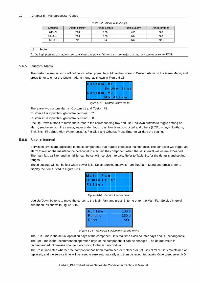
5.6.5 Custom Alarm
The custom alarm settings will not be lost when power fails. Move the cursor to Custom Alarm on the Alarm Menu, and
press Enter to enter the Custom Alarm menu, as shown in Figure 5-13.
C u s t o m # 1
S m o k e S n s r
C u s t o m # 2
N o A l a r m
Figure 5-13 Custom Alarm menu
There are two custom alarms: Custom #1 and Custom #2.
Custom #1 is input through control terminal J67.
Custom #2 is input through control terminal J68.
Use Up/Down buttons to move the cursor to the corresponding row and use Up/Down buttons to toggle among no
alarm, smoke sensor, fire sensor, water under floor, no airflow, filter obstructed and others (LCD displays No Alarm,
Smk Snsr, Fire Snsr, High Water, Loss Air, Fltr Clog and Others). Press Enter to validate the setting.
5.6.6 Service Interval
Service intervals are applicable to those components that require periodical maintenance. The controller will trigger an
alarm to remind the maintenance personnel to maintain the component when the set interval values are exceeded.
The main fan, air filter and humidifier can be set with service intervals. Refer to Table 5-1 for the defaults and setting
ranges.
These settings will not be lost when power fails. Select Service Intervals from the Alarm Menu and press Enter to
display the items listed in Figure 5-14.
M a i n F a n
H u m i d i f i e r
F i l t e r
Figure 5-14 Service Interval menu
Use Up/Down buttons to move the cursor to the Main Fan, and press Enter to enter the Main Fan Service Interval
sub-menu, as shown in Figure 5-15.
Run Time
Rpr time
Reset
100 d
360 d
NO
Figure 5-15 Main Fan Service Interval sub-menu
The Run Time is the actual operation days of the component. It is real time clock counter days and is unchangeable.
The Spr Time is the recommended operation days of the component. It can be changed. The default value is
recommended. Otherwise change it according to the actual condition.
The Reset indicates whether the component has been maintained or replaced or not. Select YES if it is maintained or
replaced, and the service time will be reset to zero automatically and then be recounted again. Otherwise, select NO.
Chapter 5 Microprocessor Control 13
Liebert_DM Chilled water Series Air Conditioner Technical Manual
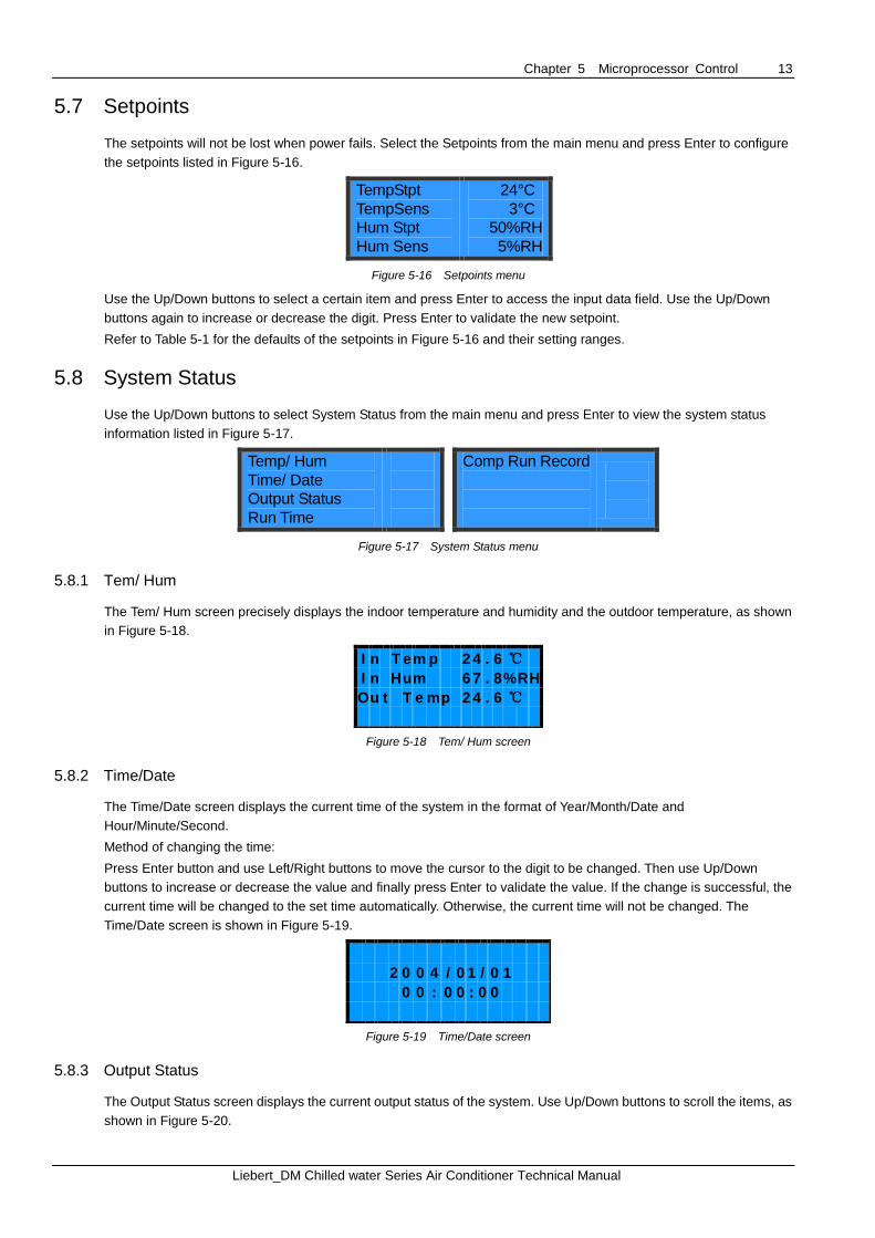
5.7 Setpoints
The setpoints will not be lost when power fails. Select the Setpoints from the main menu and press Enter to configure
the setpoints listed in Figure 5-16.
TempStpt
TempSens
Hum Stpt
Hum Sens
24°C
3°C
50%RH
5%RH
Figure 5-16 Setpoints menu
Use the Up/Down buttons to select a certain item and press Enter to access the input data field. Use the Up/Down
buttons again to increase or decrease the digit. Press Enter to validate the new setpoint.
Refer to Table 5-1 for the defaults of the setpoints in Figure 5-16 and their setting ranges.
5.8 System Status
Use the Up/Down buttons to select System Status from the main menu and press Enter to view the system status
information listed in Figure 5-17.
Temp/ Hum
Time/ Date
Output Status
Run Time
Comp Run Record
Figure 5-17 System Status menu
5.8.1 Tem/ Hum
The Tem/ Hum screen precisely displays the indoor temperature and humidity and the outdoor temperature, as shown
in Figure 5-18.
I n T e m p 2 4 . 6 ℃
I n H u m 6 7 . 8 % R H
O u t T e m p 2 4 . 6 ℃
Figure 5-18 Tem/ Hum screen
5.8.2 Time/Date
The Time/Date screen displays the current time of the system in the format of Year/Month/Date and
Hour/Minute/Second.
Method of changing the time:
Press Enter button and use Left/Right buttons to move the cursor to the digit to be changed. Then use Up/Down
buttons to increase or decrease the value and finally press Enter to validate the value. If the change is successful, the
current time will be changed to the set time automatically. Otherwise, the current time will not be changed. The
Time/Date screen is shown in Figure 5-19.
2 0 0 4 / 0 1 / 0 1
0 0 : 0 0 : 0 0
Figure 5-19 Time/Date screen
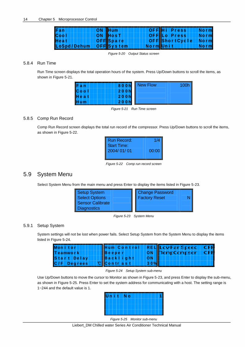
5.8.3 Output Status
The Output Status screen displays the current output status of the system. Use Up/Down buttons to scroll the items, as
shown in Figure 5-20.
14 Chapter 5 Microprocessor Control
Liebert_DM Chilled water Series Air Conditioner Technical Manual
F a n O N C o o l O N H e a t O F F L o S p d / D e h u m O F F
H u m O F F H o s T O F F S p a r e O F F S y s t e m N o r m
H i P r e s s N o r m L o P r e s s N o r m S h o r t C y c l e N o r m U n i t N o r m
Figure 5-20 Output Status screen
5.8.4 Run Time
Run Time screen displays the total operation hours of the system. Press Up/Down buttons to scroll the items, as
shown in Figure 5-21.
F a n 8 0 0 h
C o o l 2 0 0 h
H e a t 2 0 0 h
H u m 2 0 0 h
New Flow
100h
Figure 5-21 Run Time screen
5.8.5 Comp Run Record
Comp Run Record screen displays the total run record of the compressor. Press Up/Down buttons to scroll the items,
as shown in Figure 5-22.
Run Record:
Start Time:
2004/ 01/ 01
1/4
00:00
Figure 5-22 Comp run record screen
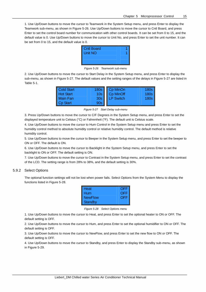
5.9 System Menu
Select System Menu from the main menu and press Enter to display the items listed in Figure 5-23.
Setup System
Select Options
Sensor Calibrate
Diagnostics
Change Password
Factory Reset
N
Figure 5-23 System Menu
5.9.1 Setup System
System settings will not be lost when power fails. Select Setup System from the System Menu to display the items
listed in Figure 5-24.
M o n i t o r
T e a m w o r k
S t a r t D e l a y
C / F D e g r e e s ℃
H u m C o n t r o l R E L
B e e p e r O N
B a c k l i g h t O N
C o n t r a s t 3 0 %
L o w F a n S p e e d O
F F
T e m p C o m p s e n O
F F
Figure 5-24 Setup System sub-menu
Use Up/Down buttons to move the cursor to Monitor as shown in Figure 5-23, and press Enter to display the sub-menu,
as shown in Figure 5-25. Press Enter to set the system address for communicating with a host. The setting range is
1~244 and the default value is 1.
U n i t N o 1
Figure 5-25 Monitor sub-menu
Chapter 5 Microprocessor Control 15
Liebert_DM Chilled water Series Air Conditioner Technical Manual
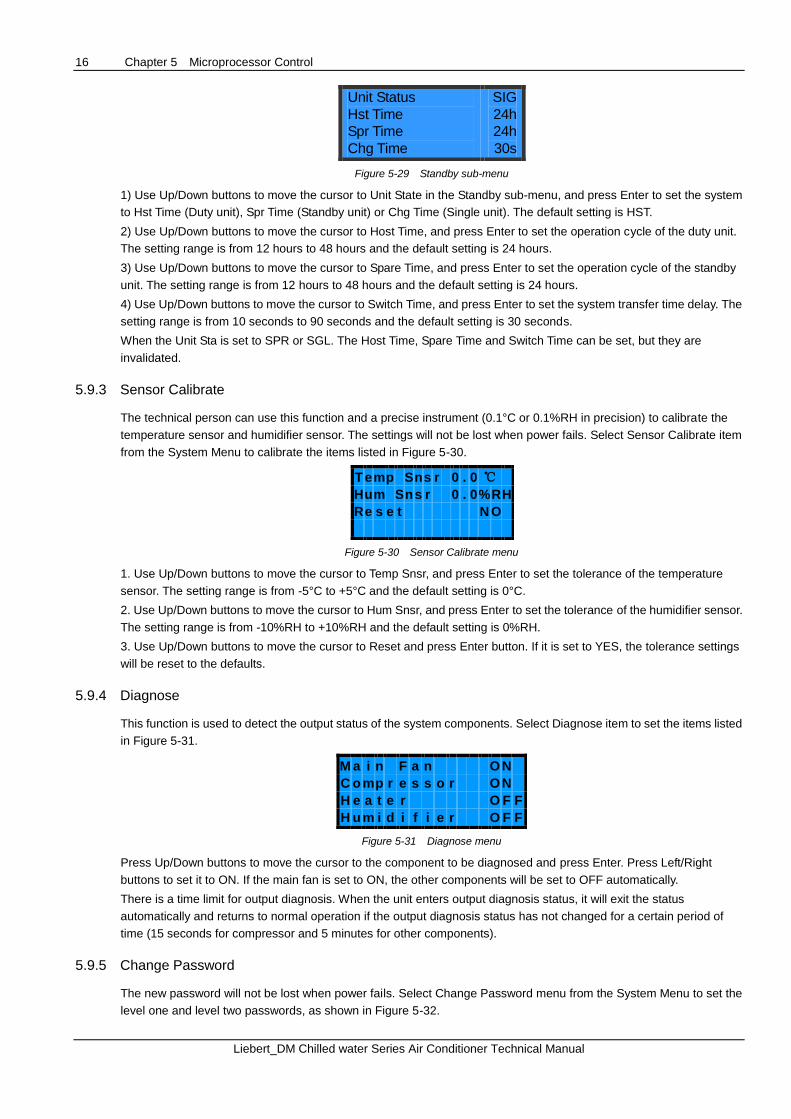
1. Use Up/Down buttons to move the cursor to Teamwork in the System Setup menu, and press Enter to display the
Teamwork sub-menu, as shown in Figure 5-26. Use Up/Down buttons to move the cursor to Cntl Board, and press
Enter to set the control board number for communication with other control boards. It can be set from 0 to 15, and the
default value is 0. Use Up/Down buttons to move the cursor to Unit No, and press Enter to set the unit number. It can
be set from 0 to 15, and the default value is 0.
Cntl Board
Unit NO
1
1
Figure 5-26 Teamwork sub-menu
2. Use Up/Down buttons to move the cursor to Start Delay in the System Setup menu, and press Enter to display the
sub-menu, as shown in Figure 5-27. The default values and the setting ranges of the delays in Figure 5-27 are listed in
Table 5-1.
Cold Start
Hot Start
Main Fan
Cp Start
180s
10s
30s
90s
Cp MinOn
Cp MinOff
LP Switch
180s
180s
180s
Figure 5-27 Start Delay sub-menu
3. Press Up/Down buttons to move the cursor to C/F Degrees in the System Setup menu, and press Enter to set the
displayed temperature unit to Celsius (°C) or Fahrenheit (°F). The default unit is Celsius scale.
4. Use Up/Down buttons to move the cursor to Hum Control in the System Setup menu and press Enter to set the
humidity control method to absolute humidity control or relative humidity control. The default method is relative
humidity control.
5. Use Up/Down buttons to move the cursor to Beeper in the System Setup menu, and press Enter to set the beeper to
ON or OFF. The default is ON.
6. Use Up/Down buttons to move the cursor to Backlight in the System Setup menu, and press Enter to set the
backlight to ON or OFF. The default setting is ON.
7. Use Up/Down buttons to move the cursor to Contrast in the System Setup menu, and press Enter to set the contrast
of the LCD. The setting range is from 28% to 38%, and the default setting is 30%.
5.9.2 Select Options
The optional function settings will not be lost when power fails. Select Options from the System Menu to display the
functions listed in Figure 5-28.
Heat
Hum
NewFlow
Standby
OFF
OFF
OFF
Figure 5-28 Select Options menu
1. Use Up/Down buttons to move the cursor to Heat, and press Enter to set the optional heater to ON or OFF. The
default setting is OFF.
2. Use Up/Down buttons to move the cursor to Hum, and press Enter to set the optional humidifier to ON or OFF. The
default setting is OFF.
3. Use Up/Down buttons to move the cursor to NewFlow, and press Enter to set the new flow to ON or OFF. The
default setting is OFF.
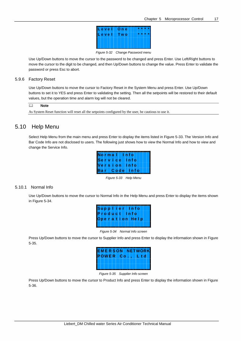
4. Use Up/Down buttons to move the cursor to Standby, and press Enter to display the Standby sub-menu, as shown
in Figure 5-29.
16 Chapter 5 Microprocessor Control
Liebert_DM Chilled water Series Air Conditioner Technical Manual
Unit Status
Hst Time
Spr Time
Chg Time
SIG
24h
24h
30s
Figure 5-29 Standby sub-menu
1) Use Up/Down buttons to move the cursor to Unit State in the Standby sub-menu, and press Enter to set the system
to Hst Time (Duty unit), Spr Time (Standby unit) or Chg Time (Single unit). The default setting is HST.
2) Use Up/Down buttons to move the cursor to Host Time, and press Enter to set the operation cycle of the duty unit.
The setting range is from 12 hours to 48 hours and the default setting is 24 hours.
3) Use Up/Down buttons to move the cursor to Spare Time, and press Enter to set the operation cycle of the standby
unit. The setting range is from 12 hours to 48 hours and the default setting is 24 hours.
4) Use Up/Down buttons to move the cursor to Switch Time, and press Enter to set the system transfer time delay. The
setting range is from 10 seconds to 90 seconds and the default setting is 30 seconds.
When the Unit Sta is set to SPR or SGL. The Host Time, Spare Time and Switch Time can be set, but they are
invalidated.
5.9.3 Sensor Calibrate
The technical person can use this function and a precise instrument (0.1°C or 0.1%RH in precision) to calibrate the
temperature sensor and humidifier sensor. The settings will not be lost when power fails. Select Sensor Calibrate item
from the System Menu to calibrate the items listed in Figure 5-30.
T e m p S n s r 0 . 0 ℃
H u m S n s r 0 . 0 % R H
R e s e t N O
Figure 5-30 Sensor Calibrate menu
1. Use Up/Down buttons to move the cursor to Temp Snsr, and press Enter to set the tolerance of the temperature
sensor. The setting range is from -5°C to +5°C and the default setting is 0°C.
2. Use Up/Down buttons to move the cursor to Hum Snsr, and press Enter to set the tolerance of the humidifier sensor.
The setting range is from -10%RH to +10%RH and the default setting is 0%RH.
3. Use Up/Down buttons to move the cursor to Reset and press Enter button. If it is set to YES, the tolerance settings
will be reset to the defaults.
5.9.4 Diagnose
This function is used to detect the output status of the system components. Select Diagnose item to set the items listed
in Figure 5-31.
M a i n F a n O N
C o m p r e s s o r O N
H e a t e r O F F
H u m i d i f i e r O F F
Figure 5-31 Diagnose menu
Press Up/Down buttons to move the cursor to the component to be diagnosed and press Enter. Press Left/Right
buttons to set it to ON. If the main fan is set to ON, the other components will be set to OFF automatically.
There is a time limit for output diagnosis. When the unit enters output diagnosis status, it will exit the status
automatically and returns to normal operation if the output diagnosis status has not changed for a certain period of
time (15 seconds for compressor and 5 minutes for other components).
5.9.5 Change Password
The new password will not be lost when power fails. Select Change Password menu from the System Menu to set the
level one and level two passwords, as shown in Figure 5-32.
Chapter 5 Microprocessor Control 17
Liebert_DM Chilled water Series Air Conditioner Technical Manual
L e v e l O n e * * * *
L e v e l T w o * * * *
Figure 5-32 Change Password menu
Use Up/Down buttons to move the cursor to the password to be changed and press Enter. Use Left/Right buttons to
move the cursor to the digit to be changed, and then Up/Down buttons to change the value. Press Enter to validate the
password or press Esc to abort.
5.9.6 Factory Reset
Use Up/Down buttons to move the cursor to Factory Reset in the System Menu and press Enter. Use Up/Down
buttons to set it to YES and press Enter to validating the setting. Then all the setpoints will be restored to their default
values, but the operation time and alarm log will not be cleared.
Note
As System Reset function will reset all the setpoints configured by the user, be cautious to use it.
5.10 Help Menu
Select Help Menu from the main menu and press Enter to display the items listed in Figure 5-33. The Version Info and
Bar Code Info are not disclosed to users. The following just shows how to view the Normal Info and how to view and
change the Service Info.
N o r m a l I n f o
S e r v i c e I n f o
V e r s i o n I n f o
B a r C o d e I n f o
Figure 5-33 Help Menu
5.10.1 Normal Info
Use Up/Down buttons to move the cursor to Normal Info in the Help Menu and press Enter to display the items shown
in Figure 5-34.
S u p p l i e r I n f o
P r o d u c t I n f o
O p e r a t i o n H e l p
Figure 5-34 Normal Info screen
Press Up/Down buttons to move the cursor to Supplier Info and press Enter to display the information shown in Figure
5-35.
E M E R S O N N E T W O R K
P O W E R C o . , L t d
Figure 5-35 Supplier Info screen
Press Up/Down buttons to move the cursor to Product Info and press Enter to display the information shown in Figure
5-36.

18 Chapter 5 Microprocessor Control
Liebert_DM Chilled water Series Air Conditioner Technical Manual
Figure 5-36 Product Info screen
Operation Help is not available at present.
5.10.2 Service Info
Select Service Info from the Help Menu and press Enter to display the items listed in Figure 5-37.
S e r v i c e B y
S e r v i c e P h o n e
S e r v i c e A C K N
S e r v i c e R e c o r d
Figure 5-37 Service Info screen
Use Up/Down buttons to move the cursor to Service By item and press Enter to view or change the information about
the service personnel, as shown in Figure 5-38.
S e r v i c e B y
L i e b e r t E n p c
Figure 5-38 Service By screen
Use Up/Down buttons to move the cursor to Service Phone item and press Enter to view or change the service phone
call, as shown in Figure 5-39.
S e r v i c e P h o n e
0 1 2 3 8 8 8 8 8 8 8 8
Figure 5-39 Service Phone screen
Press Up/Down buttons to move the cursor the Service ACK item, press Left/Right button the select Y and then press
Enter to confirm. The service information including service personnel and service time will be recorded and can be
view in the Service Record screen.
Use Up/Down buttons to move the cursor to Service Record and press Enter to view all previous service information,
as shown in Figure 5-40.
S e r v i c e R e c o r d
3 / 1 0
L i e b e r t E n p c
2 0 0 5 / 0 3 / 1 5 1 1 : 4 5
Figure 5-40 Service Record screen
Liebert_DM Chilled water Series Air Conditioner Technical Manual
Appendix 1 Control System Menu Structure
Main Menu
Spare
Hi Hum
Power Fail
Short cycle
Lo Hum
Custom #1
Custom #2
Rpr MnFan
Rpr Humid
Custom #2
Custom #1
Humidifier
Filter
Main Fan
Rpr Filter
Custom Alarm
Service Interval
Alarm Outputs
High Water
Loss Air
Fltr Colg
Other Alrm
Reset
Spr Time
Run Time
Fire Snsr
Smk Snsr
Run Time
Fan
Cool
Hum
Heat
System
Hi Press
Lo Press
Short Cycle
Unit
Setpoints
Temp Stpt
Temp Sens
Hum Sens
Lo Temp
Hi Hum
Hi Temp
Lo Hum
Hi Press
Lo Prees
Hi Temp
Lo Temp
Hum Stpt
Alarm Setpoint
Alarm Status
Alrm History
Alarm Menu
In HumTemp / Hum
Time / Date
Output Status
Heat
Hum
Lo Spd/Dehum
Host
hh:mm:ss
yyyy-mm-dd
Cool
Fan
Out Temp
System Status
In Temp
Low Fanspeed
DiagnosticsHeater
Humidifier
Level one
Level TwoChange Password
Factory Reset
Temp compsen
Heat
Hum
Standby
Temp Snsr
Hum Snsr
Main Fan
Compressor
Reset
Sensor Calibrate
Select Options
Chg Time
Spr Time
HstTime
Unit Status
Cntl BoardTeamwork
Start Delay
C/F Degree
Hum Control
Beeper
Backlight
Contrast
Setup SystemCp MinOn
Cp MinOff
LP Switch
Cold Start
Hot Start
Main fan
Cp Start
Unit No
Monitor
System Menu
Unit No
Supplier Info
Operation Help
Service By
Service Phone
Service ACK
Product Info
Service Info
Normal Info
Help Menu
Service Record
Bar Code Info
Version Info
Coil Froze
Humid Fail
Comm Fail
SnsrB Lost
Dschg Temp
Power Lost
Power PL
Power FS
Power OLVNo alarm
Reset History
Comp Run
Record
New Flow
Emerson Network Power Asia
PakistanT: 92-42-36622526 to 28F: 92-42-36622530
PhilippinesT: 63-2-7207400 F: 63-2-6203693
SingaporeT: 65-64672211F: 65-64670130
ThailandT: 66-2-6178260F: 66-2-6178277 to 78
VietnamT: 84-4-37628908F: 84-4-37628909
AustraliaT: 1800-065345F: 61-2-97810252
IndonesiaT: 62-21-2513003F: 62-21-2510622
JapanT: 81-3-54038564F: 81-3-54032919
KoreaT: 82-2-34831500F: 82-2-5927886
MalaysiaT: 603-78845000F: 603-78845188
New ZealandT: 64-3-3392060F: 64-3-3392063
While every precaution has been taken to ensure the accuracy and completeness of this literature, Emerson Network Power assumes no responsibility and disclaims all liability for damages resulting from use of this information or for any errors or omissions.
Emerson, Business-Critical Continuity and Emerson Network Power are trademarks of Emerson Electric Co. or one of its affi liated companies.
©2013 Emerson Electric Co. All rights reserved throughout the world. Specifi cations subject to change without notice.
Emerson Network Power.www.EmersonNetworkPower.AsiaThe global leader in enabling Business-Critical Continuity™.
AC Power
Connectivity
DC Power
AP13DPG-LiebertDM_ChilledWater-TM
Embedded Computing
Outside Plant Racks & Integrated CabinetsEmbedded Power
Industrial Power Power Switching & Controls Services
Infrastructure Management & Monitoring Precision Cooling