liebert air-cooled, direct-drive...
TRANSCRIPT

Liebert® Air-Cooled, Direct-Drive DrycoolersTechnical Design Manual—50 Hz & 60 Hz


i Liebert® Drycooler Technical Design Manual
Table of Content
1.0 Introduction . . . . . . . . . . . . . . . . . . . . . . . . . . . . . . . . . . . . . . . . . . . . . . . . . 1
1.1 Product Description and Features. . . . . . . . . . . . . . . . . . . . . . . . . . . . . . . . . . . . . . . . . . . . 1
1.2 Agency Listed . . . . . . . . . . . . . . . . . . . . . . . . . . . . . . . . . . . . . . . . . . . . . . . . . . . . . . . . . . . 1
1.3 Site Considerations . . . . . . . . . . . . . . . . . . . . . . . . . . . . . . . . . . . . . . . . . . . . . . . . . . . . . . . 1
2.0 Standard Features . . . . . . . . . . . . . . . . . . . . . . . . . . . . . . . . . . . . . . . . . . . . 3
2.1 Standard Features—All Drycoolers. . . . . . . . . . . . . . . . . . . . . . . . . . . . . . . . . . . . . . . . . . . 3
2.1.1 Drycooler Coil . . . . . . . . . . . . . . . . . . . . . . . . . . . . . . . . . . . . . . . . . . . . . . . . . . . . . . . . . . . 3
2.1.2 Housing. . . . . . . . . . . . . . . . . . . . . . . . . . . . . . . . . . . . . . . . . . . . . . . . . . . . . . . . . . . . . . . . 3
2.1.3 Propeller Fan . . . . . . . . . . . . . . . . . . . . . . . . . . . . . . . . . . . . . . . . . . . . . . . . . . . . . . . . . . . 3
2.1.4 Fan Motor . . . . . . . . . . . . . . . . . . . . . . . . . . . . . . . . . . . . . . . . . . . . . . . . . . . . . . . . . . . . . . 3
2.1.5 Electrical Controls . . . . . . . . . . . . . . . . . . . . . . . . . . . . . . . . . . . . . . . . . . . . . . . . . . . . . . . . 3
3.0 Specific Drycooler Types—Features . . . . . . . . . . . . . . . . . . . . . . . . . . . . . 5
3.1 Drycooler Control Types and Control Options. . . . . . . . . . . . . . . . . . . . . . . . . . . . . . . . . . . 5
3.1.1 Fan Speed—DSF, DDF . . . . . . . . . . . . . . . . . . . . . . . . . . . . . . . . . . . . . . . . . . . . . . . . . . . 5
3.1.2 Fan Cycling Control—(D)DNT, DSO, DDO. . . . . . . . . . . . . . . . . . . . . . . . . . . . . . . . . . . . . 5
3.1.3 Main Fan Control—(D)DNL. . . . . . . . . . . . . . . . . . . . . . . . . . . . . . . . . . . . . . . . . . . . . . . . . 5
3.1.4 No Controls—(D)DNC. . . . . . . . . . . . . . . . . . . . . . . . . . . . . . . . . . . . . . . . . . . . . . . . . . . . . 5
3.1.5 Pump Controls . . . . . . . . . . . . . . . . . . . . . . . . . . . . . . . . . . . . . . . . . . . . . . . . . . . . . . . . . . 5
3.2 Sound Level Options. . . . . . . . . . . . . . . . . . . . . . . . . . . . . . . . . . . . . . . . . . . . . . . . . . . . . . 5
3.2.1 Standard Drycoolers . . . . . . . . . . . . . . . . . . . . . . . . . . . . . . . . . . . . . . . . . . . . . . . . . . . . . . 5
3.2.2 Liebert Quiet-Line Drycoolers . . . . . . . . . . . . . . . . . . . . . . . . . . . . . . . . . . . . . . . . . . . . . . . 5
4.0 Typical System Configurations . . . . . . . . . . . . . . . . . . . . . . . . . . . . . . . . . 7
5.0 Drycooler Performance Data & Selection . . . . . . . . . . . . . . . . . . . . . . . . 17
6.0 Dimensions and Weights . . . . . . . . . . . . . . . . . . . . . . . . . . . . . . . . . . . . . 19
6.1 Drycooler Dimensions and Anchor Plans . . . . . . . . . . . . . . . . . . . . . . . . . . . . . . . . . . . . . 19
7.0 Piping . . . . . . . . . . . . . . . . . . . . . . . . . . . . . . . . . . . . . . . . . . . . . . . . . . . . . 25
7.1 Piping Considerations . . . . . . . . . . . . . . . . . . . . . . . . . . . . . . . . . . . . . . . . . . . . . . . . . . . . 25
7.2 Glycol/Inhibitor Solution. . . . . . . . . . . . . . . . . . . . . . . . . . . . . . . . . . . . . . . . . . . . . . . . . . . 25
7.3 Piping Connections . . . . . . . . . . . . . . . . . . . . . . . . . . . . . . . . . . . . . . . . . . . . . . . . . . . . . . 26

Liebert® Drycooler Technical Design Manual ii
8.0 Pump Packagesand Expansion Tank—Ancillary Items . . . . . . . . . . . . . . . . . . . . . . . . . 29
9.0 Electrical Data . . . . . . . . . . . . . . . . . . . . . . . . . . . . . . . . . . . . . . . . . . . . . . 33
9.1 Line Voltage Electrical Data . . . . . . . . . . . . . . . . . . . . . . . . . . . . . . . . . . . . . . . . . . . . . . . 33
9.2 Low-Voltage Control Wiring. . . . . . . . . . . . . . . . . . . . . . . . . . . . . . . . . . . . . . . . . . . . . . . . 37
9.3 Electrical Connection Diagrams . . . . . . . . . . . . . . . . . . . . . . . . . . . . . . . . . . . . . . . . . . . . 39
10.0 Engineering Data, Calculations and Selection Procedure . . . . . . . . . 45
11.0 Guide Specifications . . . . . . . . . . . . . . . . . . . . . . . . . . . . . . . . . . . . . . . . 49

iii Liebert® Drycooler Technical Design Manual
List of FiguresFigure 1-1: Liebert 3-fan drycooler. . . . . . . . . . . . . . . . . . . . . . . . . . . . . . . . . . . . . . . . . . . . . . . . . . . . . . . . . . . . . . 1
Figure 1-2: Product model nomenclature. . . . . . . . . . . . . . . . . . . . . . . . . . . . . . . . . . . . . . . . . . . . . . . . . . . . . . . . . 2
Figure 4-1: Piping diagram, Liebert DS™ with glycol with semi-hermetic compressor models . . . . . . . . . . . . . . . . 8
Figure 4-2: Piping diagram, Liebert DS™ with water/glycol with semi-hermetic compressor models . . . . . . . . . . . 9
Figure 4-3: Piping diagram, Liebert DS™ with water/glycol with digital scroll compressor models . . . . . . . . . . . . 10
Figure 4-4: Piping diagram, Liebert DS™ with GLYCOOL with semi-hermetic compressor models . . . . . . . . . . . 11
Figure 4-5: Piping diagram, Liebert DS™ with GLYCOOL with scroll compressor models . . . . . . . . . . . . . . . . . . 12
Figure 4-6: Piping diagram, Liebert DS™ with GLYCOOL with digital scroll compressors . . . . . . . . . . . . . . . . . . 13
Figure 4-7: Piping diagram, Liebert PDX™ with water/glycol . . . . . . . . . . . . . . . . . . . . . . . . . . . . . . . . . . . . . . . . 14
Figure 4-8: Piping diagram, Liebert PDX™ with GLYCOOL . . . . . . . . . . . . . . . . . . . . . . . . . . . . . . . . . . . . . . . . . 15
Figure 4-9: Typical piping arrangement, multiple drycoolers and multiple indoor units . . . . . . . . . . . . . . . . . . . . . 16
Figure 6-1: Drycooler planning dimensional data—One- and two-fan units. . . . . . . . . . . . . . . . . . . . . . . . . . . . . . 21
Figure 6-2: Drycooler planning dimensional data—Three- and four-fan units . . . . . . . . . . . . . . . . . . . . . . . . . . . . 22
Figure 6-3: Drycooler planning dimensional data—Six- and eight-fan units . . . . . . . . . . . . . . . . . . . . . . . . . . . . . 23
Figure 6-4: Typical drycooler footprint—dimensions . . . . . . . . . . . . . . . . . . . . . . . . . . . . . . . . . . . . . . . . . . . . . . . 24
Figure 7-1: Piping connection locations for 1-, 2-, 3- and 4-fan drycoolers . . . . . . . . . . . . . . . . . . . . . . . . . . . . . . 26
Figure 7-2: Piping connection locations for 6 and 8 fan drycoolers . . . . . . . . . . . . . . . . . . . . . . . . . . . . . . . . . . . . 27
Figure 8-1: Pump curve, 60 Hz . . . . . . . . . . . . . . . . . . . . . . . . . . . . . . . . . . . . . . . . . . . . . . . . . . . . . . . . . . . . . . . 29
Figure 8-2: Single-pump package and mounting . . . . . . . . . . . . . . . . . . . . . . . . . . . . . . . . . . . . . . . . . . . . . . . . . . 30
Figure 8-3: Dual-pump package and mounting . . . . . . . . . . . . . . . . . . . . . . . . . . . . . . . . . . . . . . . . . . . . . . . . . . . 31
Figure 8-4: Expansion tank . . . . . . . . . . . . . . . . . . . . . . . . . . . . . . . . . . . . . . . . . . . . . . . . . . . . . . . . . . . . . . . . . . 32
Figure 9-1: Electrical field connections, 1-fan DSF/DDF drycooler with pump control. . . . . . . . . . . . . . . . . . . . . . 39
Figure 9-2: Electrical field connections, 1-, 2-, 3- and 4-fan DSO/DDO drycooler with pump control . . . . . . . . . . 40
Figure 9-3: Electrical field connections, 6- and 8-fan DSO/DDO drycooler with pump control . . . . . . . . . . . . . . . 41
Figure 9-4: Electrical field connections, 6- and 8-fan DDNC drycooler without pump control . . . . . . . . . . . . . . . . 42
Figure 9-5: Electrical field connections, 6- and 8-fan DDNL/DDNT drycooler without pump control . . . . . . . . . . . 43
Figure 10-1: Capacity correction factor . . . . . . . . . . . . . . . . . . . . . . . . . . . . . . . . . . . . . . . . . . . . . . . . . . . . . . . . . 46
Figure 10-2: Pressure drop correction factor . . . . . . . . . . . . . . . . . . . . . . . . . . . . . . . . . . . . . . . . . . . . . . . . . . . . . 46
Liebert® Drycooler Technical Design Manual iv
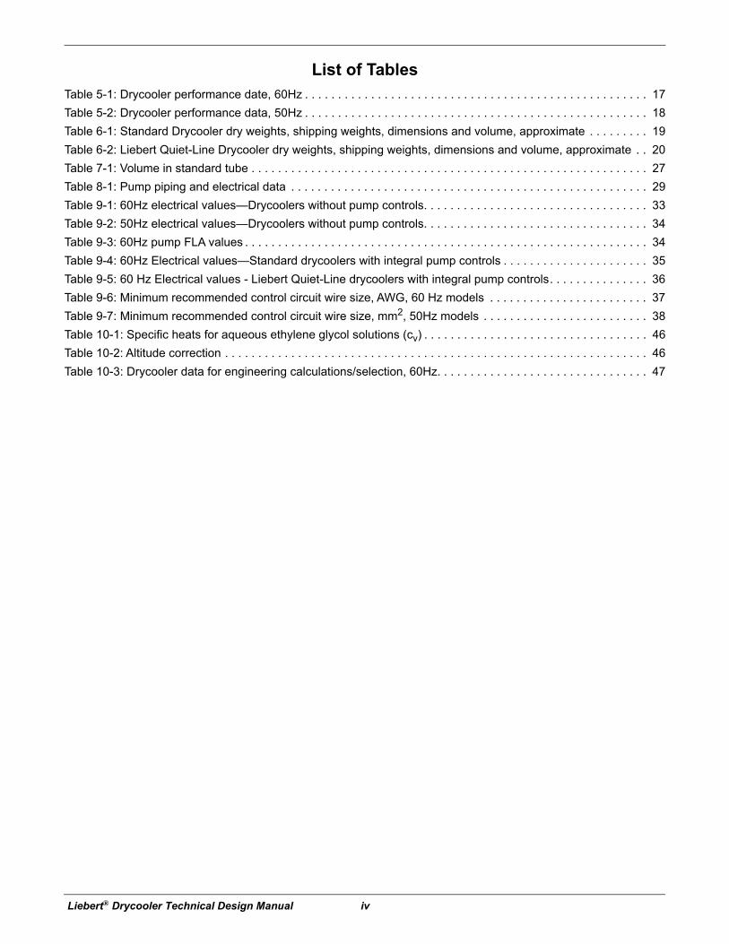
List of TablesTable 5-1: Drycooler performance date, 60Hz . . . . . . . . . . . . . . . . . . . . . . . . . . . . . . . . . . . . . . . . . . . . . . . . . . . . 17
Table 5-2: Drycooler performance data, 50Hz . . . . . . . . . . . . . . . . . . . . . . . . . . . . . . . . . . . . . . . . . . . . . . . . . . . . 18
Table 6-1: Standard Drycooler dry weights, shipping weights, dimensions and volume, approximate . . . . . . . . . 19
Table 6-2: Liebert Quiet-Line Drycooler dry weights, shipping weights, dimensions and volume, approximate . . 20
Table 7-1: Volume in standard tube . . . . . . . . . . . . . . . . . . . . . . . . . . . . . . . . . . . . . . . . . . . . . . . . . . . . . . . . . . . . 27
Table 8-1: Pump piping and electrical data . . . . . . . . . . . . . . . . . . . . . . . . . . . . . . . . . . . . . . . . . . . . . . . . . . . . . . 29
Table 9-1: 60Hz electrical values—Drycoolers without pump controls. . . . . . . . . . . . . . . . . . . . . . . . . . . . . . . . . . 33
Table 9-2: 50Hz electrical values—Drycoolers without pump controls. . . . . . . . . . . . . . . . . . . . . . . . . . . . . . . . . . 34
Table 9-3: 60Hz pump FLA values . . . . . . . . . . . . . . . . . . . . . . . . . . . . . . . . . . . . . . . . . . . . . . . . . . . . . . . . . . . . . 34
Table 9-4: 60Hz Electrical values—Standard drycoolers with integral pump controls . . . . . . . . . . . . . . . . . . . . . . 35
Table 9-5: 60 Hz Electrical values - Liebert Quiet-Line drycoolers with integral pump controls. . . . . . . . . . . . . . . 36
Table 9-6: Minimum recommended control circuit wire size, AWG, 60 Hz models . . . . . . . . . . . . . . . . . . . . . . . . 37
Table 9-7: Minimum recommended control circuit wire size, mm2, 50Hz models . . . . . . . . . . . . . . . . . . . . . . . . . 38
Table 10-1: Specific heats for aqueous ethylene glycol solutions (cv) . . . . . . . . . . . . . . . . . . . . . . . . . . . . . . . . . . 46
Table 10-2: Altitude correction . . . . . . . . . . . . . . . . . . . . . . . . . . . . . . . . . . . . . . . . . . . . . . . . . . . . . . . . . . . . . . . . 46
Table 10-3: Drycooler data for engineering calculations/selection, 60Hz. . . . . . . . . . . . . . . . . . . . . . . . . . . . . . . . 47

Introduction
1 Liebert® Drycooler Technical Design Manual
1.0 Introduction
1.1 Product Description and FeaturesThe Liebert drycooler is a low-profile, direct-drive propeller fan-type air-cooled unit. Constructed with an aluminum cabinet and a copper-tube aluminum fin coil, the unit is quiet and corrosion resistant. All electrical connections and controls are enclosed in an integral NEMA 3R rated electrical panel section of the drycooler.
Figure 1-1 Liebert 3-fan drycooler
1.2 Agency ListedStandard 60Hz units are CSA certified to the harmonized U.S. and Canadian product safety standard, CSA C22.2 No 236/UL 1995 for “Heating and Cooling Equipment” and are marked with the CSA c-us logo.
1.3 Site ConsiderationsWhen considering installation locations, consider that these units reject heat into the atmosphere and should be located in a clean air area, away from loose dirt and foreign matter that may clog the coil. The drycoolers and pumps should be installed in a location offering maximum security and access for maintenance. Avoid ground level sites with public access and areas that are subject to heavy snow or ice accumulations and sites in the vicinity of steam, hot air or fume exhausts. Drycoolers should be located no closer than 3 feet from a wall, obstruction or adjacent unit. There should be no obstructions over the unit. Drycoolers must not be installed in a pit, where discharge air is likely to be recirculated through the drycooler or installed where objects restrict the air inlet free area.
The drycooler must be installed on a level surface to ensure proper glycol flow, venting and drainage. For roof installation, mount the drycooler on suitable curbs or other supports in accordance with local codes. To minimize sound and vibration transmission, mount steel supports across load-bearing walls. Utilize Piggyback drycoolers whenever interior building locations must be used.
C US
R

Introduction
Liebert® Drycooler Technical Design Manual 2
Allow adequate space for pump packages, expansion/compression tanks, piping and additional field supplied devices. When mounting pump packages, mount on level surface or suitable curbs that will allow cooling ventilation air to enter from underneath the pump package frame and exit through the louvers.
Figure 1-2 Product model nomenclature
D N 350 A 48
N = No Pump ControlS = Single Pump ControlD= Dual Pump Control
P = 208/230V-1ph-60Hz *W = 200/220V-1ph-50HzY = 208/230V-3ph-60HzA = 460V-3ph-60HzB = 575V-3ph-60HzM = 380/415V-3ph-50Hz
Optional Disconnect Switch on Models with No Pump Control
C = No Fan ControlL = Main Fan ControlT = Fan CyclingO = Fan Cycling and Pump
ControlS = Special Order Fan/Pump
ControlF = Fan Speed Control
Model Size
Example: DDNT350A48
D
Drycooler
T
* Single-phase input voltage available only on DSF and DDF drycoolers and will require single-phase pumps. For single-phase voltage on other drycoolers, consult factory for SFA DC2022 availability.** See 7.3 - Piping Connections for standard and optional circuits available
48 = Optional Circuiting (Blank for Standard Circuiting) **

Standard Features
3 Liebert® Drycooler Technical Design Manual
2.0 Standard Features
2.1 Standard Features—All DrycoolersLiebert drycoolers consist of drycooler coil(s), housing, propeller fan(s) direct-driven by individual fan motor(s), electrical controls and mounting legs. Liebert air-cooled drycoolers provide for heat rejection needs of glycol-cooled Thermal Management units by using outdoor air to remove heat from circulating water/glycol mixtures and to maintain water/glycol temperatures within designed and controlled ranges. Various control methods are employed to match indoor unit type, indoor unit to drycooler/pump combinations and maximum sound requirements.
2.1.1 Drycooler CoilLiebert-manufactured coils are constructed of copper tubes in a staggered tube pattern. Tubes are expanded into continuous, corrugated aluminum fins. The fins have full-depth fin collars completely covering the copper tubes, which are connected to heavy wall Type “L” headers. Inlet coil connector tubes pass through relieved holes in the tube sheet for maximum resistance to piping strain and vibration. Coil circuit options can be selected and factory built to provide the right combination of heat transfer and pressure drop for the glycol system. The glycol supply and return pipes are either spun shut (1-4 fan) or capped (6-fan and 8-fan) at the factory and include a factory-installed Schrader valve. Coils are factory leak-tested at a minimum of 300 psig (2068kPag), dehydrated, then filled with an inert gas holding charge for shipment and sealed.
2.1.2 HousingThe condenser housing is fabricated from bright aluminum sheet and divided into individual fan sections by full-width baffles. Structural support members, including coil support frame, motor and drive support, are galvanized steel for strength and corrosion resistance. Aluminum legs are provided for mounting the unit for vertical discharge and have rigging holes for hoisting the unit into position. The unit’s electrical panel is inside an integral NEMA 3R weatherproof section of the housing.
2.1.3 Propeller FanAluminum propeller fan blades are secured to a corrosion-protected steel hub. Fan guards are heavy gauge, close-meshed steel wire with corrosion-resistant polyester paint finish rated to pass a 1000-hour salt spray test. Fans are secured to the fan motor shaft by a keyed hub and dual setscrews. Fan diameter is 26" (660mm) or less. The fans are factory-balanced and run before shipment.
2.1.4 Fan MotorThe drycooler’s fan motor is a continuous air-over design equipped with rain shield and permanently sealed bearing. Die-formed, galvanized steel supports are used for rigid mounting of the motor.
2.1.5 Electrical ControlsElectrical controls, overload protection devices and service connection terminals are factory-wired inside the integral electrical panel section of the housing. A locking disconnect switch is factory-mounted and wired to the electrical panel and controlled via an externally mounted locking door handle. An indoor unit interlock circuit enables drycooler operation whenever the indoor unit’s compressors are active. Supply wiring and indoor unit interlock wiring are required at drycooler installation, along with any pumps controlled by the drycooler’s electrical panel.

Standard Features
Liebert® Drycooler Technical Design Manual 4
Page intentionally left blank.
Specific Drycooler Types—Features
5 Liebert® Drycooler Technical Design Manual
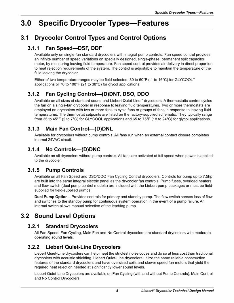
3.0 Specific Drycooler Types—Features
3.1 Drycooler Control Types and Control Options
3.1.1 Fan Speed—DSF, DDFAvailable only on single-fan standard drycoolers with integral pump controls. Fan speed control provides an infinite number of speed variations on specially designed, single-phase, permanent split capacitor motor, by monitoring leaving fluid temperature. Fan speed control provides air delivery in direct proportion to heat rejection requirements of the system. The control is adjustable to maintain the temperature of the fluid leaving the drycooler.
Either of two temperature ranges may be field-selected: 30 to 60°F (-1 to 16°C) for GLYCOOL™ applications or 70 to 100°F (21 to 38°C) for glycol applications.
3.1.2 Fan Cycling Control—(D)DNT, DSO, DDOAvailable on all sizes of standard sound and Liebert Quiet-Line™ drycoolers. A thermostatic control cycles the fan on a single-fan drycooler in response to leaving fluid temperatures. Two or more thermostats are employed on drycoolers with two or more fans to cycle fans or groups of fans in response to leaving fluid temperatures. The thermostat setpoints are listed on the factory-supplied schematic. They typically range from 35 to 45°F (2 to 7°C) for GLYCOOL applications and 65 to 75°F (18 to 24°C) for glycol applications.
3.1.3 Main Fan Control—(D)DNLAvailable for drycoolers without pump controls. All fans run when an external contact closure completes internal 24VAC circuit.
3.1.4 No Controls—(D)DNCAvailable on all drycoolers without pump controls. All fans are activated at full speed when power is applied to the drycooler.
3.1.5 Pump ControlsAvailable on all Fan Speed and DSO/DDO Fan Cycling Control drycoolers. Controls for pump up to 7.5hp are built into the same integral electric panel as the drycooler fan controls. Pump fuses, overload heaters and flow switch (dual pump control models) are included with the Liebert pump packages or must be field-supplied for field-supplied pumps.
Dual Pump Option—Provides controls for primary and standby pump. The flow switch senses loss of flow and switches to the standby pump for continuous system operation in the event of a pump failure. An internal switch allows manual selection of the lead/lag pump.
3.2 Sound Level Options
3.2.1 Standard DrycoolersAll Fan Speed, Fan Cycling, Main Fan and No Control drycoolers are standard drycoolers with moderate operating sound levels.
3.2.2 Liebert Quiet-Line DrycoolersLiebert Quiet-Line drycoolers can help meet the strictest noise codes and do so at less cost than traditional drycoolers with acoustic shielding. Liebert Quiet-Line drycoolers utilize the same reliable construction features of the standard drycoolers and have oversized coils and slower speed fan motors that yield the required heat rejection needed at significantly lower sound levels.
Liebert Quiet-Line Drycoolers are available on Fan Cycling (with and without Pump Controls), Main Control and No Control Drycoolers.

Specific Drycooler Types—Features
Liebert® Drycooler Technical Design Manual 6
Page intentionally left blank.
Typical System Configurations
7 Liebert® Drycooler Technical Design Manual
4.0 Typical System ConfigurationsThe standard glycol-cooled Precision Cooling system includes these major components:
• Indoor air conditioning unit with heat exchangers (refrigerant/glycol)
• Glycol regulating valve
• Outdoor air-cooled drycooler
• Glycol pump(s)
• Expansion/compression tank
• Pump controls
• Interconnection piping
• Unit interlock control wiring
Figures 4-1 and 4-6 show a single unit to drycooler loop arrangement. Figure 4-9 shows a typical configuration of multiple indoor units and multiple outdoor drycoolers using a dual pump package and on a common piping loop. Additional field-supplied components, such as valves, expansion tank, strainers and flow or pressure switches are also shown in Figures 4-1, 4-6 and 4-9. These components are necessary and should be included when designing a system with one indoor and one outdoor unit on a piping loop or a system using multiple indoor and outdoor units on a common piping loop. Larger systems may also benefit from an air separator (not shown).

Typical System Configurations
Liebert® Drycooler Technical Design Manual 8
Figure 4-1 Piping diagram, Liebert DS™ with glycol with semi-hermetic compressor models
NOTE: SCHEMATIC REPRESENTATION SHOWN. THIS SCHEMATIC DOES NOT IMPLY OR DEFINE ELEVATIONS AND COMPONENT LOCATION, UNLESS SPECIFICALLY NOTED.
ServiceValve
ServiceValve
Components are not supplied byLiebert but are required forproper operation and maintenanceField installed at highest point in system onreturn line to pumpsLocate at tops of all risers and any intermediatesystem high points
ExternalEqualizer
Sensing BulbCylinderUnloader(s)
NOTE: TWO REFRIGERATION CIRCUITS PROVIDED. SINGLE REFRIGERATION CIRCUIT SHOWN FOR CLARITY.
FIELD PIPINGFACTORY PIPING
Muffler
EVAPORATORCOIL
ExpansionValve
COMPRESSOR
LIQUID
SUCTION
SightGlass
SolenoidValve
Filter DrierPARADENSER®
CONDENSER
TO SECONDREFRIGERATION
CIRCUIT
HoseBib
Shut-Off ValveHoseBib
Shut-Off Valve
Flow-Regulating Valve
Flow Switch Suppliedwith Dual PumpSystems
Pressure Port
Gate Valves
Check Valves(on Dual PumpSystems only)
GLYCOLPUMPS
EXPANSIONTANK
HoseBib
COOLING TOWERAND PUMP SYSTEM
BY OTHERS
SERVICE / SCHRADER (ACCESS) CONNECTION WITH VALVE CORESERVICE / SCHRADER (ACCESS) CONNECTION NO VALVE COREOPTIONAL FACTORY PIPING
AquastatSensingBulbs
PressurePort
2-WayRegulatingValve
Sensor
Optional3-WayRegulatingValve
By-Pass Valve
Optional Dual Pump System shown
DRYCOOLER(Glycol)
Air Vents(typical)Shut-Off Valve
Shut-Off Valve
CUSTOMERHEAT REJECTION
LIEBERTHEAT REJECTION
LIEBERT DS UNIT (and associated piping)
RETURN SUPPLY
RETURN SUPPLY
RETURN SUPPLY
DISCHARGE
Relief valve(s) suppliedwith 50 Hz EU CE units rated maximum480 PSIG (33 Bar).
Check Valve
1
2
3
11
1
11
1
1
1
1
1
1
1
2
3
DPN000895Rev. 6
Typical System Configurations
9 Liebert® Drycooler Technical Design Manual
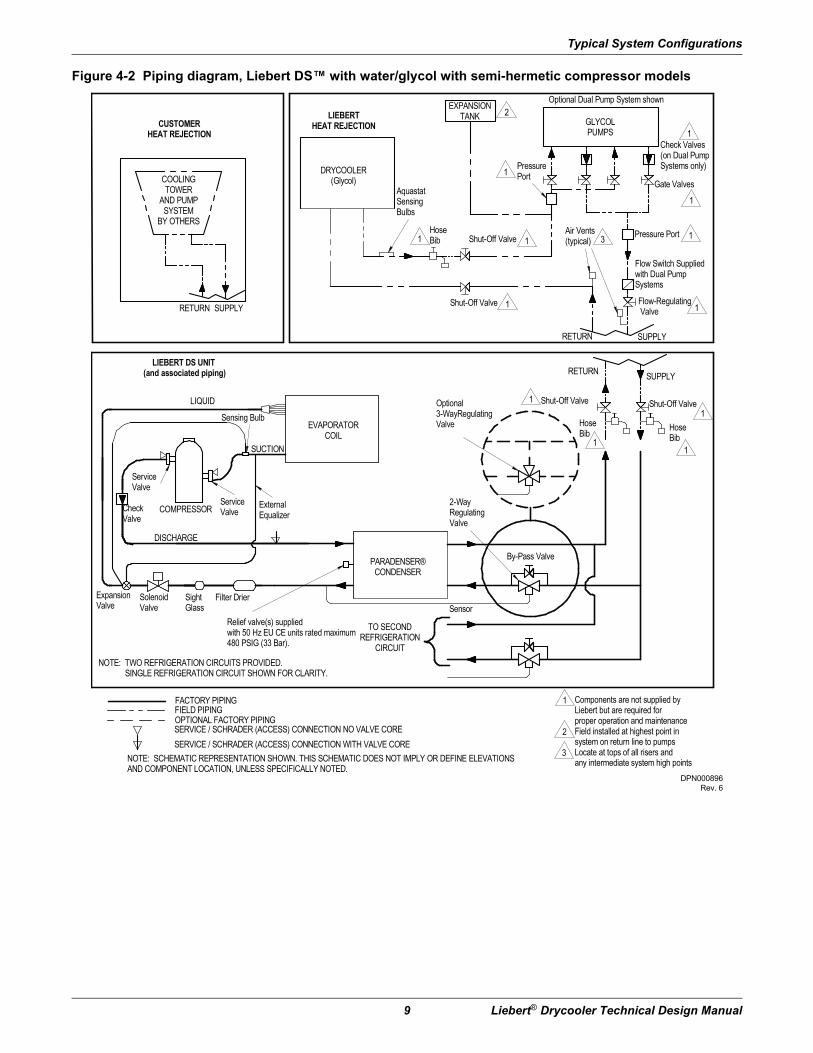
Figure 4-2 Piping diagram, Liebert DS™ with water/glycol with semi-hermetic compressor models
NOTE: SCHEMATIC REPRESENTATION SHOWN. THIS SCHEMATIC DOES NOT IMPLY OR DEFINE ELEVATIONSAND COMPONENT LOCATION, UNLESS SPECIFICALLY NOTED.
ServiceValve
ServiceValve
Components are not supplied byLiebert but are required forproper operation and maintenanceField installed at highest point insystem on return line to pumpsLocate at tops of all risers andany intermediate system high points
ExternalEqualizer
Sensing Bulb
NOTE: TWO REFRIGERATION CIRCUITS PROVIDED. SINGLE REFRIGERATION CIRCUIT SHOWN FOR CLARITY.
FIELD PIPINGFACTORY PIPING
CheckValve
EVAPORATORCOIL
ExpansionValve
COMPRESSOR
LIQUID
SUCTION
SightGlass
SolenoidValve
Filter Drier
PARADENSER®CONDENSER
TO SECONDREFRIGERATION
CIRCUIT
HoseBib
Shut-Off Valve
HoseBib
Shut-Off Valve
Flow-Regulating Valve
Flow Switch Suppliedwith Dual PumpSystems
Pressure Port
Gate Valves
Check Valves(on Dual PumpSystems only)
GLYCOLPUMPS
EXPANSIONTANK
HoseBib
SERVICE / SCHRADER (ACCESS) CONNECTION WITH VALVE CORESERVICE / SCHRADER (ACCESS) CONNECTION NO VALVE COREOPTIONAL FACTORY PIPING
AquastatSensingBulbs
PressurePort
2-WayRegulatingValve
Sensor
Optional3-WayRegulatingValve
By-Pass Valve
Optional Dual Pump System shown
DRYCOOLER(Glycol)
Air Vents(typical)Shut-Off Valve
Shut-Off Valve
RETURN SUPPLY
RETURN SUPPLY
DISCHARGE
COOLINGTOWER
AND PUMPSYSTEM
BY OTHERS
CUSTOMERHEAT REJECTION
LIEBERTHEAT REJECTION
LIEBERT DS UNIT (and associated piping)
RETURN SUPPLY
Relief valve(s) suppliedwith 50 Hz EU CE units rated maximum480 PSIG (33 Bar).
3
2
1
1
1
1
1
1
1
1
1
1
1
1
1
2
3
DPN000896Rev. 6

Typical System Configurations
Liebert® Drycooler Technical Design Manual 10
Figure 4-3 Piping diagram, Liebert DS™ with water/glycol with digital scroll compressor models
NOTE: SCHEMATIC REPRESENTATION SHOWN. THIS SCHEMATIC DOES NOT IMPLY OR DEFINE ELEVATIONSAND COMPONENT LOCATION, UNLESS SPECIFICALLY NOTED.
ServiceValve
ServiceValve
Components are not supplied by Liebert but arerequired for proper operation and maintenanceField installed at highest point in system on returnline to pumpsLocate at tops of all risers and any intermediatesystem high points
ExternalEqualizer
Sensing Bulb
NOTE: TWO REFRIGERATION CIRCUITS PROVIDED. SINGLE REFRIGERATION CIRCUIT SHOWN FOR CLARITY.
FIELD PIPINGFACTORY PIPING
CheckValve
EVAPORATORCOIL
ExpansionValve
COMPRESSOR
LIQUID
SUCTION
SightGlass
SolenoidValve
Filter Drier
PARADENSER®CONDENSER
TO SECONDREFRIGERATION
CIRCUIT
HoseBib
Shut-Off Valve
HoseBib
Shut-Off Valve
Flow-Regulating Valve
Flow Switch Suppliedwith Dual PumpSystems
Pressure Port
Gate Valves
Check Valves(on Dual PumpSystems only)
GLYCOLPUMPS
EXPANSIONTANK
HoseBib
SERVICE / SCHRADER (ACCESS) CONNECTION WITH VALVE CORESERVICE / SCHRADER (ACCESS) CONNECTION NO VALVE COREOPTIONAL FACTORY PIPING
AquastatSensingBulbs
PressurePort
2-WayMotorizedBall Valve
Optional 3-WayMotorized BallValve
Optional Dual Pump System shown
DRYCOOLER(Glycol)
Air Vents(typical)Shut-Off Valve
Shut-Off Valve
RETURN SUPPLY
RETURN SUPPLY
DISCHARGE
COOLING TOWERAND PUMP SYSTEM
BY OTHERS
CUSTOMERHEAT REJECTION
LIEBERTHEAT REJECTION
LIEBERT DS UNIT (and associated piping)
RETURN SUPPLY
Relief valve(s) suppliedwith 50 Hz EU CE units ratedmaximum 480 PSIG (33 Bar).
PressureTransducer
ToiCOMControl
FromiCOMControl
53-70kW DigitalSolenoid Valve
28-42kW Digital Solenoid Valve
3
2
1
11
11
1
1
1
1
1
11
1
2
3
DPN001430Rev. 2

Typical System Configurations
11 Liebert® Drycooler Technical Design Manual
Figure 4-4 Piping diagram, Liebert DS™ with GLYCOOL with semi-hermetic compressor models
NOTE: SCHEMATIC REPRESENTATION SHOWN. THIS SCHEMATIC DOES NOT IMPLY OR DEFINE ELEVATIONSAND COMPONENT LOCATION, UNLESS SPECIFICALLY NOTED.
ServiceValve
ServiceValve
Components are not supplied byLiebert but are required for proper operationand maintenanceField installed at highest point in system onreturn line to pumpsLocate at tops of all risers and any intermediatesystem high points
ExternalEqualizer
Sensing BulbCylinderUnloader(s)
NOTE: TWO REFRIGERATION CIRCUITS PROVIDED. SINGLE REFRIGERATION CIRCUIT SHOWN FOR CLARITY.
FIELD PIPINGFACTORY PIPING
EVAPORATORCOIL
ExpansionValve
COMPRESSOR
LIQUID
SUCTION
SightGlass
SolenoidValve
Filter Drier
PARADENSER®CONDENSER
TO SECONDREFRIGERATION
CIRCUIT
HoseBib
Shut-Off Valve
HoseBib
Shut-Off Valve
Flow-Regulating Valve
Flow Switch Suppliedwith Dual PumpSystems
Pressure Port
Gate Valves
Check Valves(on Dual PumpSystems only)
GLYCOLPUMPS
EXPANSIONTANK
HoseBib
ECON-O-COIL
SERVICE / SCHRADER (ACCESS) CONNECTION WITH VALVE CORESERVICE / SCHRADER (ACCESS) CONNECTION NO VALVE CORE
AquastatSensingBulbs
PressurePort
3-WayRegulatingValve
Sensor
Optional Dual Pump System shown
DRYCOOLER(Glycol)
Air Vents(typical)Shut-Off Valve
Shut-Off Valve
RETURN SUPPLY
RETURN SUPPLY
DISCHARGE
3-WayChilled GlycolValve
Thermistor
LIEBERTHEAT REJECTION
LIEBERT DS UNIT(and associated piping)
Relief valve(s) suppliedwith 50 Hz EU CE units rated maximum480 PSIG (33 Bar).
Muffler
Check Valve
3
2
1
11
1 1
1
1
1
1
11
1
1
2
3
DPN000897Rev. 5
Typical System Configurations
Liebert® Drycooler Technical Design Manual 12
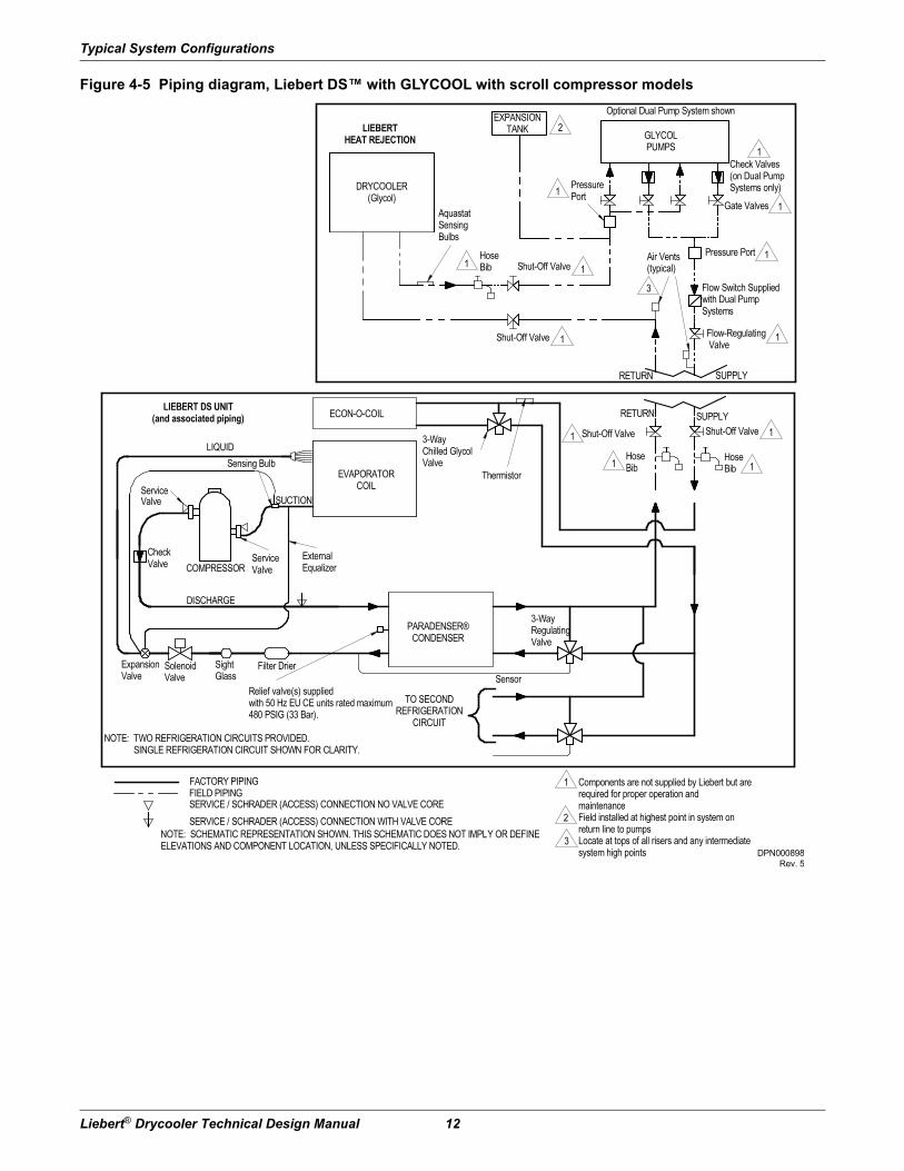
Figure 4-5 Piping diagram, Liebert DS™ with GLYCOOL with scroll compressor models
NOTE: SCHEMATIC REPRESENTATION SHOWN. THIS SCHEMATIC DOES NOT IMPLY OR DEFINEELEVATIONS AND COMPONENT LOCATION, UNLESS SPECIFICALLY NOTED.
ServiceValve
Components are not supplied by Liebert but arerequired for proper operation andmaintenanceField installed at highest point in system onreturn line to pumpsLocate at tops of all risers and any intermediatesystem high points
ExternalEqualizer
Sensing Bulb
NOTE: TWO REFRIGERATION CIRCUITS PROVIDED. SINGLE REFRIGERATION CIRCUIT SHOWN FOR CLARITY.
FIELD PIPINGFACTORY PIPING
CheckValve
EVAPORATORCOIL
ExpansionValve
COMPRESSOR
LIQUID
SUCTION
SightGlass
SolenoidValve
Filter Drier
PARADENSER®CONDENSER
TO SECONDREFRIGERATION
CIRCUIT
HoseBib
Shut-Off Valve
HoseBib
Shut-Off Valve
Flow-Regulating Valve
Flow Switch Suppliedwith Dual PumpSystems
Pressure Port
Gate Valves
Check Valves(on Dual PumpSystems only)
GLYCOLPUMPS
EXPANSIONTANK
HoseBib
ECON-O-COIL
SERVICE / SCHRADER (ACCESS) CONNECTION WITH VALVE CORESERVICE / SCHRADER (ACCESS) CONNECTION NO VALVE CORE
AquastatSensingBulbs
PressurePort
3-WayRegulatingValve
Sensor
Optional Dual Pump System shown
DRYCOOLER(Glycol)
Air Vents(typical)Shut-Off Valve
Shut-Off Valve
LIEBERTHEAT REJECTION
LIEBERT DS UNIT(and associated piping)
RETURN SUPPLY
RETURN SUPPLY
DISCHARGE
3-WayChilled GlycolValve
Thermistor
Relief valve(s) suppliedwith 50 Hz EU CE units rated maximum480 PSIG (33 Bar).
3
2
1
1
1
1
1
1
1
1
1
1
1
1
1
2
3
ServiceValve
DPN000898Rev. 5
Typical System Configurations
13 Liebert® Drycooler Technical Design Manual
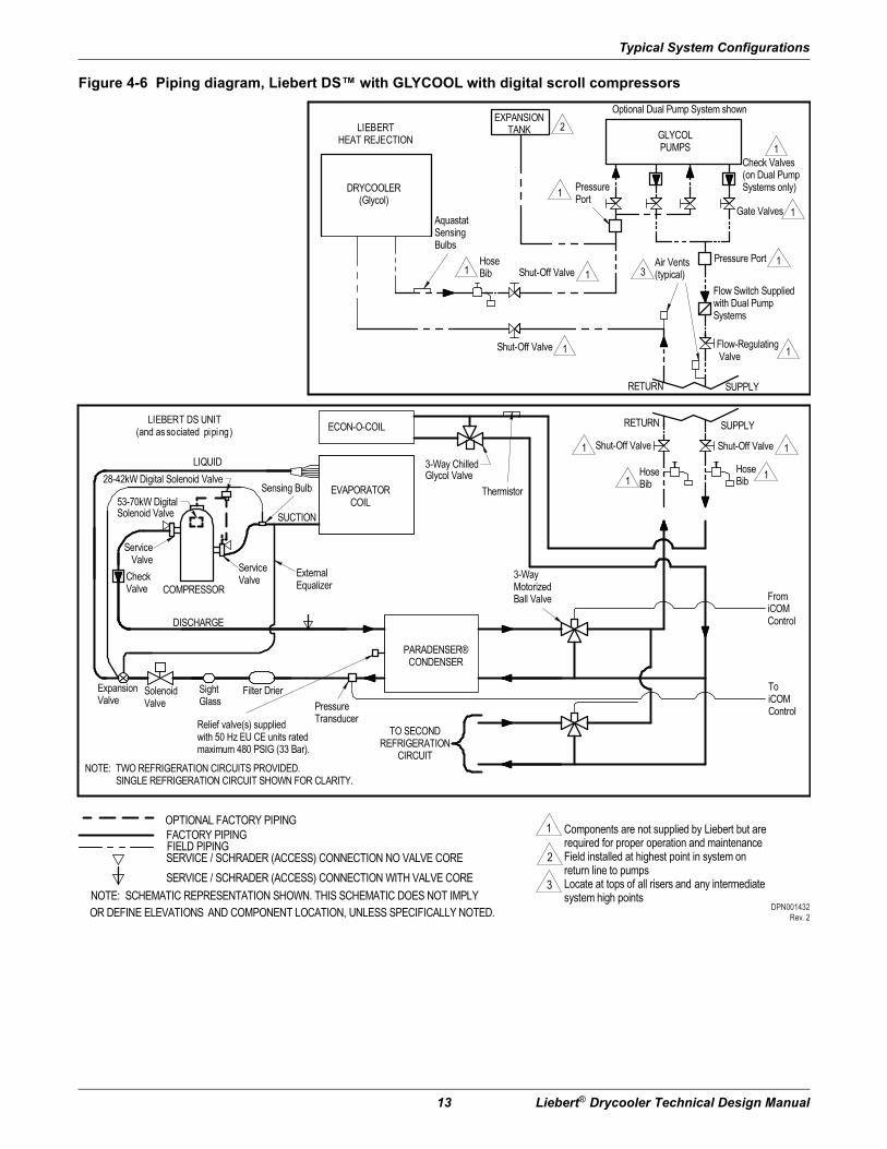
Figure 4-6 Piping diagram, Liebert DS™ with GLYCOOL with digital scroll compressors
NOTE: SCHEMATIC REPRESENTATION SHOWN. THIS SCHEMATIC DOES NOT IMPLY OR DEFINE ELEVATIONS AND COMPONENT LOCATION, UNLESS SPECIFICALLY NOTED.
ServiceValve
ServiceValve
Components are not supplied by Liebert but arerequired for proper operation and maintenanceField installed at highest point in system onreturn line to pumpsLocate at tops of all risers and any intermediatesystem high points
ExternalEqualizer
Sensing Bulb
NOTE: TWO REFRIGERATION CIRCUITS PROVIDED. SINGLE REFRIGERATION CIRCUIT SHOWN FOR CLARITY.
FIELD PIPINGFACTORY PIPING
CheckValve
EVAPORATORCOIL
ExpansionValve
COMPRESSOR
LIQUID
SUCTION
SightGlass
SolenoidValve
Filter Drier
PARADENSER®CONDENSER
TO SECONDREFRIGERATION
CIRCUIT
HoseBib
Shut-Off Valve
HoseBib
Shut-Off Valve
Flow-Regulating Valve
Flow Switch Suppliedwith Dual PumpSystems
Pressure Port
Gate Valves
Check Valves(on Dual PumpSystems only)
GLYCOLPUMPS
EXPANSIONTANK
HoseBib
ECON-O-COIL
SERVICE / SCHRADER (ACCESS) CONNECTION WITH VALVE CORESERVICE / SCHRADER (ACCESS) CONNECTION NO VALVE CORE
AquastatSensingBulbs
PressurePort
3-WayMotorizedBall Valve
Optional Dual Pump System shown
DRYCOOLER(Glycol)
Air Vents(typical)Shut-Off Valve
Shut-Off Valve
LIEBERTHEAT REJECTION
LIEBERT DS UNIT(and associated piping)
RETURN SUPPLY
RETURN SUPPLY
DISCHARGE
Thermistor
Relief valve(s) suppliedwith 50 Hz EU CE units ratedmaximum 480 PSIG (33 Bar).
PressureTransducer
ToiCOMControl
FromiCOMControl
28-42kW Digital Solenoid Valve
53-70kW DigitalSolenoid Valve
3
2
1
11
1 1
1
1
1
1
1 1
1
2
3
1
OPTIONAL FACTORY PIPING
3-Way ChilledGlycol Valve
DPN001432Rev. 2

Typical System Configurations
Liebert® Drycooler Technical Design Manual 14
Figure 4-7 Piping diagram, Liebert PDX™ with water/glycol
ServiceValve
ServiceValve
ExternalEqualizer
Sensing BulbDigital Solenoid Valve
FIELD PIPINGFACTORY PIPING
CheckValve
EVAPORATORCOIL
ExpansionValve
COMPRESSOR
LIQUID
SUCTION
SightGlass
Filter Drier
HEATEXCHANGER
HoseBib*
Shut-Off Valve*HoseBib*
Flow-Regulating Valve*
Flow SwitchSupplied with DualPump Systems
Pressure Port*
Gate Valves*
Check Valves*(on Dual PumpSystems only)
GLYCOLPUMPS
EXPANSIONTANK**
HoseBib*
SERVICE / SCHRADER (ACCESS) CONNECTION WITH VALVE CORE
SERVICE / SCHRADER (ACCESS) CONNECTION NO VALVE CORE
OPTIONAL FACTORY PIPING
AquastatSensingBulbs
PressurePort*
2-WayMotorizedBall Valve
Optional 3-WayMotorized BallValve
Optional Dual Pump System shown
DRYCOOLER(Glycol)
Air Vents(typical)***Shut-Off Valve*
Shut-Off Valve*
RETURN SUPPLY
RETURN SUPPLY
DISCHARGE
COOLING TOWERAND PUMP
SYSTEMBY OTHERS
CUSTOMERHEAT REJECTION
LIEBERTHEAT REJECTION
LIEBERT PDX UNIT (and associated piping)
RETURN SUPPLY
PressureTransducer
ToiCOMControl
FromiCOMControl
Y-Strainer+
NOTES: 1. SCHEMATIC REPRESENTATION SHOWN. DO NOT USE FOR SPECIFIC CONNECTION LOCATIONS.2. INSTALL A 20 MESH STRAINER, IN AN EASILY ACCESSIBLE LOCATION, ON THE WATER/GLYCOL SUPPLY TO PREVENT PARTICLES FROM ENTERING THE HEAT EXCHANGER. STRAINER BYPASS VALVES ARE RECOMMENDED TO ALLOW THE STRAINER TO BE CLEANED WHILE MAINTAINING FLOW TO THE COOLING UNIT.
* Components are not supplied by Liebert, but are required for proper circuit operation and maintenance** Field installed at highest point in system on return line to pumps*** Locate at tops of all risers and any intermediate system high points+ Components are Liebert supplied and field installed, and are required for proper circuit operation and maintenance.++ Components are not supplied by Liebert but are recommended for proper circuit operation and maintenance.
Shut-off Valve(3) Places ++
DPN002931Rev. 2

Typical System Configurations
15 Liebert® Drycooler Technical Design Manual
Figure 4-8 Piping diagram, Liebert PDX™ with GLYCOOL
ServiceValve
ServiceValve
ExternalEqualizer
Sensing Bulb
FIELD PIPINGFACTORY PIPING
CheckValve
EVAPORATORCOIL
ExpansionValve
COMPRESSOR
LIQUID
SUCTION
SightGlass
Filter Drier
HEATEXCHANGER
HoseBib*
Shut-Off Valve*HoseBib*
Flow-Regulating Valve*
Flow SwitchSupplied with DualPump Systems
Pressure Port*
Gate Valves*
Check Valves*(on Dual PumpSystems only)
GLYCOLPUMPS
EXPANSIONTANK**
HoseBib*
ECON-O-COIL
SERVICE / SCHRADER (ACCESS) CONNECTION WITH VALVE CORE
SERVICE / SCHRADER (ACCESS) CONNECTION NO VALVE CORE
AquastatSensingBulbs
PressurePort*
3-WayMotorizedBall Valve
Optional Dual Pump System shown
DRYCOOLER(Glycol)
Air Vents(typical)***Shut-Off Valve*
Shut-Off Valve*
LIEBERTHEAT REJECTION
LIEBERT PDX UNIT(and associated piping)
RETURN SUPPLY
RETURN SUPPLY
DISCHARGE
3-WayChilled GlycolValve
ThermistorDigital Solenoid Valve
ToiCOMControl
FromiCOMControl
Shut-off Valve(3) Places ++
Y-Strainer+
NOTES: 1. SCHEMATIC REPRESENTATION SHOWN. DO NOT USE FOR SPECIFIC CONNECTION LOCATIONS.2. INSTALL A 20 MESH STRAINER, IN AN EASILY ACCESSIBLE LOCATION, ON THE WATER/GLYCOL SUPPLY TO PREVENT PARTICLES FROM ENTERING THE HEAT EXCHANGER. STRAINER BYPASS VALVES ARE RECOMMENDED TO ALLOW THE STRAINER TO BE CLEANED WHILE MAINTAINING FLOW TO THE COOLING UNIT.
* Components are not supplied by Liebert, but are required for proper circuit operation and maintenance** Field installed at highest point in system on return line to pumps*** Locate at tops of all risers and any intermediate system high points+ Components are Liebert supplied and field installed, and are required for proper circuit operation and maintenance.++ Components are not supplied by Liebert but are recommended for proper circuit operation and maintenance.
PressureTransducer
DPN002932Rev. 2
Typical System Configurations
Liebert® Drycooler Technical Design Manual 16
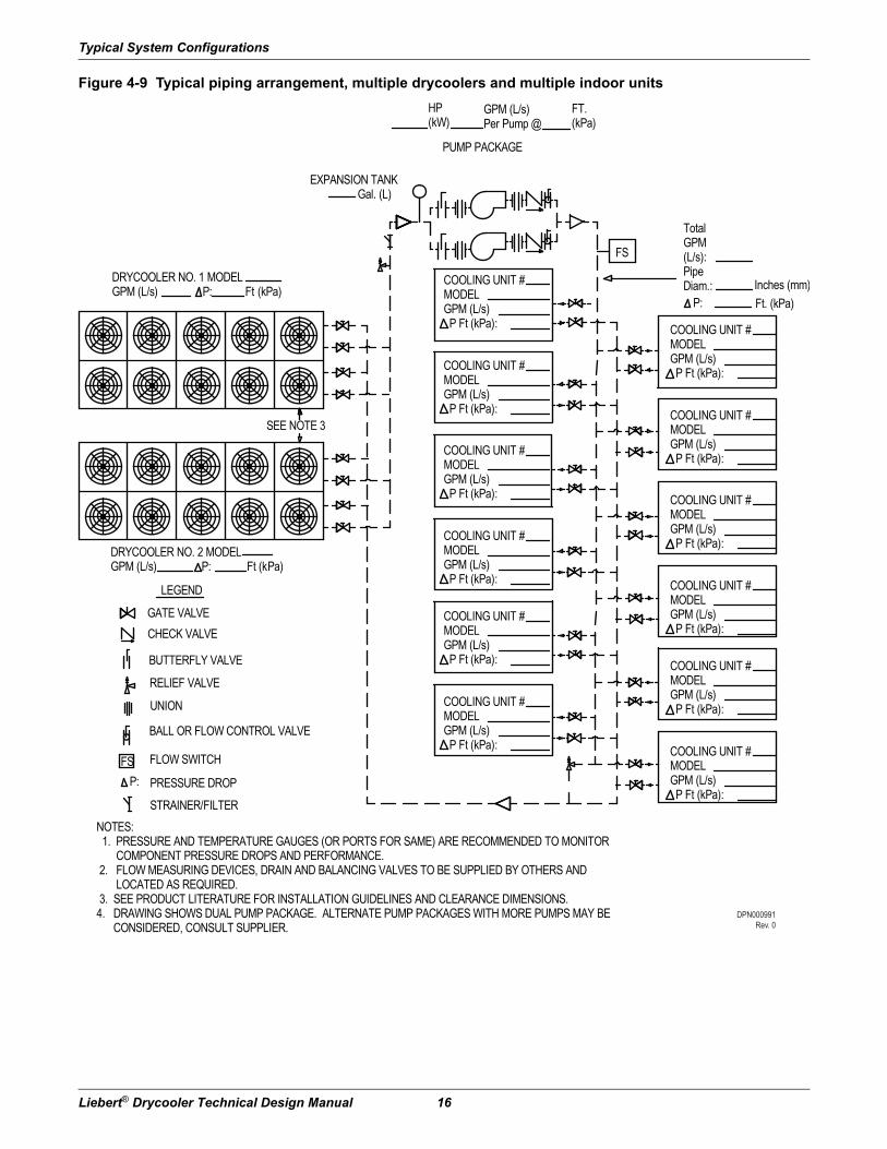
Figure 4-9 Typical piping arrangement, multiple drycoolers and multiple indoor units
LEGEND
GATE VALVECHECK VALVE
RELIEF VALVE
UNION
BALL OR FLOW CONTROL VALVE
FLOW SWITCH
PRESSURE DROPP:FS
FS
TotalGPM(L/s):PipeDiam.: Inches (mm)
P: Ft. (kPa)
DRYCOOLER NO. 1 MODELGPM (L/s) P: Ft (kPa)
DRYCOOLER NO. 2 MODELGPM (L/s) P: Ft (kPa)
EXPANSION TANK Gal. (L)
HP(kW)
GPM (L/s)Per Pump @
FT.(kPa)
PUMP PACKAGE
SEE NOTE 3
COOLING UNIT #MODELGPM (L/s) P Ft (kPa):
NOTES: 1. PRESSURE AND TEMPERATURE GAUGES (OR PORTS FOR SAME) ARE RECOMMENDED TO MONITOR COMPONENT PRESSURE DROPS AND PERFORMANCE. 2. FLOW MEASURING DEVICES, DRAIN AND BALANCING VALVES TO BE SUPPLIED BY OTHERS AND LOCATED AS REQUIRED. 3. SEE PRODUCT LITERATURE FOR INSTALLATION GUIDELINES AND CLEARANCE DIMENSIONS.4. DRAWING SHOWS DUAL PUMP PACKAGE. ALTERNATE PUMP PACKAGES WITH MORE PUMPS MAY BE CONSIDERED, CONSULT SUPPLIER.
COOLING UNIT #MODELGPM (L/s) P Ft (kPa):
COOLING UNIT #MODELGPM (L/s) P Ft (kPa):
COOLING UNIT #MODELGPM (L/s) P Ft (kPa):
COOLING UNIT #MODELGPM (L/s) P Ft (kPa):
COOLING UNIT #MODELGPM (L/s) P Ft (kPa):
COOLING UNIT #MODELGPM (L/s) P Ft (kPa):
COOLING UNIT #MODELGPM (L/s) P Ft (kPa):
COOLING UNIT #MODELGPM (L/s) P Ft (kPa):
COOLING UNIT #MODELGPM (L/s) P Ft (kPa):
COOLING UNIT #MODELGPM (L/s) P Ft (kPa):
COOLING UNIT #MODELGPM (L/s) P Ft (kPa):
BUTTERFLY VALVE
STRAINER/FILTER
DPN000991Rev. 0

Drycooler Performance Data & Selection
17 Liebert® Drycooler Technical Design Manual
5.0 Drycooler Performance Data & SelectionTable 5-1 Drycooler performance date, 60Hz
Standard Unit (Circuits) Data Fans Direct Drive
ModelNumber
*D**
Total HeatRejection,
kBtuh (kW)@25F ITD
GlycolFlow Rate, GPM (lpm)
PressureDrop,
Ft. H20 (kPa)
No. ofInternalCircuits
(Std.)No. of Fans
BladeDiameter,
in (cm)
RatedMotor
hp Air Flow
(CFM)
SoundPower,
LwA
SoundPressure,
dBA**
Standard Models
033 38 (11.1) 10 (38) 9.1 (27) 4
1
26 (66) 3/4
7200 86.5 72.5
069 67 (19.6) 20 (76) 8.9 (27) 8 6870 86.5 72.5
092 92 (27.1) 30 (114) 8.6 (26) 12 6600 86.5 72.5
109 109 (31.9) 40 (152) 8.1 (24) 16 6300 86.5 72.5
112 118 (34.6) 40 (152) 10.1 (30) 16 6090 86.5 72.5
139 134 (39.3) 40 (152) 7.1 (21) 16
2
13700 91.0 75.5
174 173 (50.8) 40 (152) 10.5 (31) 16 13300 91.0 75.5
197 197 (57.7) 40 (152) 13.9 (42) 16 12645 91.0 75.5
225 231 (67.7) 65 (246) 10.9 (33) 26 12200 91.1 75.5
260 260 (76.3) 60 (227) 10.1 (30) 24
3
19900 94.0 77.3
310 311 (91.0) 80 (303) 9.8 (29) 32 19000 94.0 77.3
350 353 (103) 80 (303) 14.6 (44) 32 17400 94.0 77.3
352 328 (96.2) 60 (227) 12.9 (39) 24
4
24800 94.4 78.5
419 394 (115) 80 (303) 12.7 (38) 32 23650 94.4 78.5
466 441 (129) 100 (379) 12.7 (38) 40 22800 94.4 78.5
491 469 (137) 120 (455) 12.8 (38) 48 21700 94.4 78.5
620 621 (182) 160 (606) 9.8 (29) 64
6
37900 96.8 80.3
650 652 (191) 130 (493) 15.2 (45) 52 36500 96.8 80.3
700 706 (207) 160 (606) 14.6 (44) 64 34800 96.8 80.3
790 787 (231) 160 (606) 12.7 (38) 64
8
47300 97.4 81.5
880 882 (258) 200 (758) 12.7 (38) 80 45500 97.4 81.5
940 938 (275) 240 (910) 12.5 (37) 96 43400 97.4 81.5
Liebert Quiet-Line™ Models
040 44 (13.0) 20 (76) 8.8 (26) 8
1
26 (66) 1/4
3110 68.9 56.5
057 57 (16.7) 30 (114) 8.6 (26) 12 2990 68.9 56.5
060 63 (18.4) 40 (152) 8.1 (24) 16 2840 68.9 56.5
080 89 (26.0) 40 (152) 7.0 (21) 16
2
6220 72.6 59.5
111 111 (32.5) 40 (152) 10.4 (31) 16 5980 72.6 59.5
121 121 (35.4) 40 (152) 13.7 (41) 16 5680 72.6 59.5
158 166 (48.7) 60 (227) 10.0 (30) 24
3
8970 74.8 61.3
173 185 (54.2) 80 (303) 9.7 (29) 32 8520 74.8 61.3
178 186 (54.5) 80 (303) 14.5 (43) 32 7440 74.8 61.3
205 219 (64.2) 60 (227) 12.9 (39) 244
11680 76.2 62.5
248 248 (72.8) 80 (303) 12.5 (37) 32 11360 76.2 62.5
347 369 (108) 160 (606) 9.8 (29) 646
17040 78.4 64.3
356 372 (109) 160 (606) 14.6 (44) 64 14880 78.4 64.3
453 496 (145) 160 (606) 12.6 (38) 648
22720 79.9 65.5
498 505 (148) 240 (910) 12.4 (37) 96 19840 79.9 65.5Standard data based on 95 °F (35 °C) EAT, 120 °F (48.9 °C) EFT, 40% E.G.Capacity shown is drycooler THR at sea level.Sound Pressure is dBA @ 5ft (1.5m)

Drycooler Performance Data & Selection
Liebert® Drycooler Technical Design Manual 18
Table 5-2 Drycooler performance data, 50Hz
ModelNumber
*D**
Standard Circuits Data Fans Direct Drive
Total HeatRejection, kBtuh (kW)@ 25F ITD
Glycol Flow Rate,
GPM (lpm)
PressureDrop,
Ft. H20
(kPa)
No. ofInternalCircuits
(Std.)No. of Fans
Blade Diameter,
in (cm)
RatedMotor
hp
AirFlow
(CFM)
Sound Power,
LwA
SoundPressure,
dBA**
Standard Models
033 35 (10.3) 10 (38) 9.1 (27) 4
1
26 (66) 3/4
6000 82.5 69.1
069 60 (17.4) 20 (76) 8.9 (27) 8 5700 82.5 69.1
092 82 (23.9) 30 (114) 8.6 (26) 12 5500 81.7 68.3
109 95 (27.7) 40 (152) 8.1 (24) 16 5300 81.7 68.3
112 104 (30.3) 40 (152) 10.1 (30) 16 5100 81.7 68.3
139 119 (34.8) 40 (152) 7.1 (21) 16
2
11400 85.9 71.8
174 153 (44.5) 40 (152) 10.5 (31) 16 11100 85.9 71.8
197 175 (51.0) 40 (152) 13.9 (42) 16 10500 85.9 71.8
225 204 (59.4) 65 (246) 10.9 (33) 26 10100 85.9 71.8
260 230 (67.1) 60 (227) 10.1 (30) 24
3
16600 89.4 73.7
310 274 (80.0) 80 (303) 9.8 (29) 32 15800 89.4 73.7
350 312 (91.0) 80 (303) 14.6 (44) 32 14500 89.4 73.7
352 290 (84.5) 60 (227) 12.9 (39) 24
4
20700 91.0 75.7
419 347 (101) 80 (303) 12.7 (38) 32 19700 91.0 75.7
466 389 (114) 100 (379) 12.7 (38) 40 19000 91.0 75.7
491 416 (121) 120 (455) 12.8 (38) 48 18100 91.0 75.7
620 549 (160) 160 (606) 9.8 (29) 64
6
31600 92.4 76.7
650 577 (168) 130 (493) 15.2 (45) 52 30400 92.4 76.7
700 624 (182) 160 (606) 14.6 (44) 64 2900 92.4 76.7
790 697 (203) 160 (606) 12.7 (38) 64
8
39400 94.0 78.7
880 781 (228) 200 (758) 12.7 (38) 80 37900 94.0 78.7
940 830 (242) 240 (910) 12.5 (37) 96 36200 94.0 78.7
Liebert Quiet-Line™ Models
040 19 (5.6) 20 (76) 8.8 (26) 8
1
26 (66) 1/4
2600 65.6 53.2
057 45 (13.2) 30 (114) 8.6 (26) 12 2500 65.6 53.2
060 52 (15.3) 40 (152) 8.1 (24) 16 2400 65.6 53.2
080 65 (19.2) 40 (152) 7.0 (21) 16
2
5200 69.3 56.2
111 84 (24.7) 40 (152) 10.4 (31) 16 5000 69.3 56.2
121 96 (28.2) 40 (152) 13.7 (41) 16 4700 69.3 56.2
158 127 (37.1) 60 (227) 10.0 (30) 24
3
7500 71.5 58.0
173 151 (44.2) 80 (303) 9.7 (29) 32 7100 71.5 58.0
178 172 (50.3) 80 (303) 14.5 (43) 32 6200 71.5 58.0
205 160 (46.7) 60 (227) 12.9 (39) 244
9700 72.9 59.2
248 191 (55.9) 80 (303) 12.5 (37) 32 9500 72.9 59.2
347 302 (88) 160 (606) 9.8 (29) 646
14200 75.1 61.0
356 343 (101) 160 (606) 14.6 (44) 64 12400 75.1 61.0
453 383 (112) 160 (606) 12.6 (38) 648
18900 76.6 62.2
498 457 (134) 240 (910) 12.4 (37) 96 16500 76.6 62.2
Standard data based on 95 °F (35 °C) EAT, 120 °F (48.9 °C) EFT, 40% E.G.Capacity shown is drycooler THR at sea level.Sound Pressure is dBA @ 5ft (1.5m)

Dimensions and Weights
19 Liebert® Drycooler Technical Design Manual
6.0 Dimensions and Weights
6.1 Drycooler Dimensions and Anchor PlansTable 6-1 Standard Drycooler dry weights, shipping weights, dimensions and volume, approximate
ModelNo. of Fans
Dry Weight lb (kg)
Domestic Packed Export Packed
Weight Dimension (LxWxH) Volume Weight Dimension (LxWxH) Volume
lb. (kg) in. (cm) ft3 (m3) lb. (kg.) in. (cm) ft3 (m3)
*D**033
1
355 (161) 510 (231)
62x36x63 (157x91x160) 81 (2.3)
617 (280)
63x37x64 (160x94x163) 86 (2.5)
*D**069 375 (170) 530 (240) 637 (289)
*D**092 395 (179) 550 (249) 657 (298)
*D**109 415 (188) 570 (259) 677 (307)
*D**112 435 (197) 590 (268) 697 (316)
*D**139
2
500 (227) 757 (343)
102x36x63 (259x91x160) 134 (3.8)
914 (415)
103x37x64 (262x94x163) 141 (4.0)*D**174 540 (245) 797 (362) 954 (433)
*D**197 580 (263) 837 (380) 994 (451)
*D**225 620 (281) 877 (398) 1034 (469)
*D**260
3
735 (333) 1104 (501)
142x36x63 (361x91x160) 186 (5.3)
1282 (582)
143x37x64 (363x94x163) 196 (5.6)*D**310 795 (361) 1164 (528) 1342 (609)
*D**350 855 (388) 1224 (555) 1402 (636)
*D**352
4
940 (426) 1401 (635)
182x36x63 (462x91x160) 239 (6.7)
1658 (752)
183x37x64 (465x94x163) 251 (7.0)*D**419 1020 (463) 1481 (672) 1738 (788)
*D**466 1050 (476) 1511 (685) 1768 (802)
*D**491 1100 (499) 1561 (708) 1818 (825)
*D**620
6
1780 (808) 2223 (1008)
142x36x94 (361x91x239) 278 (7.9)
2948 (1337)
143x37x95 (363x94x241) 291 (8.2)*D**650 1830 (831) 2273 (1031) 2998 (1360)
*D**700 1880 (854) 2323 (1054) 3048 (1383)
*D**790
8
2250 (1022) 2815 (1277)
182x36x94 (462x91x239) 356 (10.0)
3769 (1710)
183x37x95 (465x94x241) 372 (10.5)*D**880 2330 (1058) 2895 (1313) 3849 (1746)
*D**940 2430 (1103) 2995 (1359) 3949 (1791)
Dimensions and Weights
Liebert® Drycooler Technical Design Manual 20
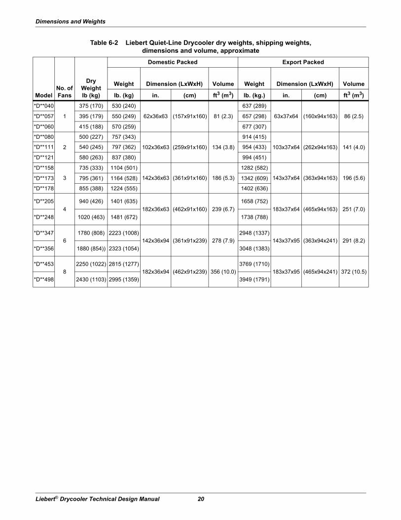
Table 6-2 Liebert Quiet-Line Drycooler dry weights, shipping weights, dimensions and volume, approximate
ModelNo. of Fans
Dry Weight lb (kg)
Domestic Packed Export Packed
Weight Dimension (LxWxH) Volume Weight Dimension (LxWxH) Volume
lb. (kg) in. (cm) ft3 (m3) lb. (kg.) in. (cm) ft3 (m3)
*D**040
1
375 (170) 530 (240)
62x36x63 (157x91x160) 81 (2.3)
637 (289)
63x37x64 (160x94x163) 86 (2.5)*D**057 395 (179) 550 (249) 657 (298)
*D**060 415 (188) 570 (259) 677 (307)
*D**080
2
500 (227) 757 (343)
102x36x63 (259x91x160) 134 (3.8)
914 (415)
103x37x64 (262x94x163) 141 (4.0)*D**111 540 (245) 797 (362) 954 (433)
*D**121 580 (263) 837 (380) 994 (451)
*D**158
3
735 (333) 1104 (501)
142x36x63 (361x91x160) 186 (5.3)
1282 (582)
143x37x64 (363x94x163) 196 (5.6)*D**173 795 (361) 1164 (528) 1342 (609)
*D**178 855 (388) 1224 (555) 1402 (636)
*D**205
4
940 (426) 1401 (635)
182x36x63 (462x91x160) 239 (6.7)
1658 (752)
183x37x64 (465x94x163) 251 (7.0)
*D**248 1020 (463) 1481 (672) 1738 (788)
*D**3476
1780 (808) 2223 (1008)142x36x94 (361x91x239) 278 (7.9)
2948 (1337)143x37x95 (363x94x241) 291 (8.2)
*D**356 1880 (854)) 2323 (1054) 3048 (1383)
*D**4538
2250 (1022) 2815 (1277)182x36x94 (462x91x239) 356 (10.0)
3769 (1710)183x37x95 (465x94x241) 372 (10.5)
*D**498 2430 (1103) 2995 (1359) 3949 (1791)
Dimensions and Weights
21 Liebert® Drycooler Technical Design Manual
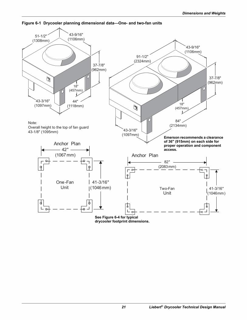
Figure 6-1 Drycooler planning dimensional data—One- and two-fan units
51-1/2"(1308mm)
43-9/16"(1106mm)
37-7/8"(962mm)
18"(457mm)
91-1/2"(2324mm)
44"(1118mm)
43-3/16"(1097mm)
Note:Overall height to the top of fan guard43-1/8" (1095mm)
43-9/16"(1106mm)
37-7/8"(962mm)
18"(457mm)
84"(2134mm)
43-3/16"(1097mm)
41-3/16"(1046mm)
42"(1067mm)
One-Fan 41-3/16"
(1046mm)
82"(2083mm)
Two-Fan
UnitUnit
Anchor Plan
Anchor Plan
Emerson recommends a clearance of 36" (915mm) on each side for proper operation and component access.
See Figure 6-4 for typical drycooler footprint dimensions.
Dimensions and Weights
Liebert® Drycooler Technical Design Manual 22
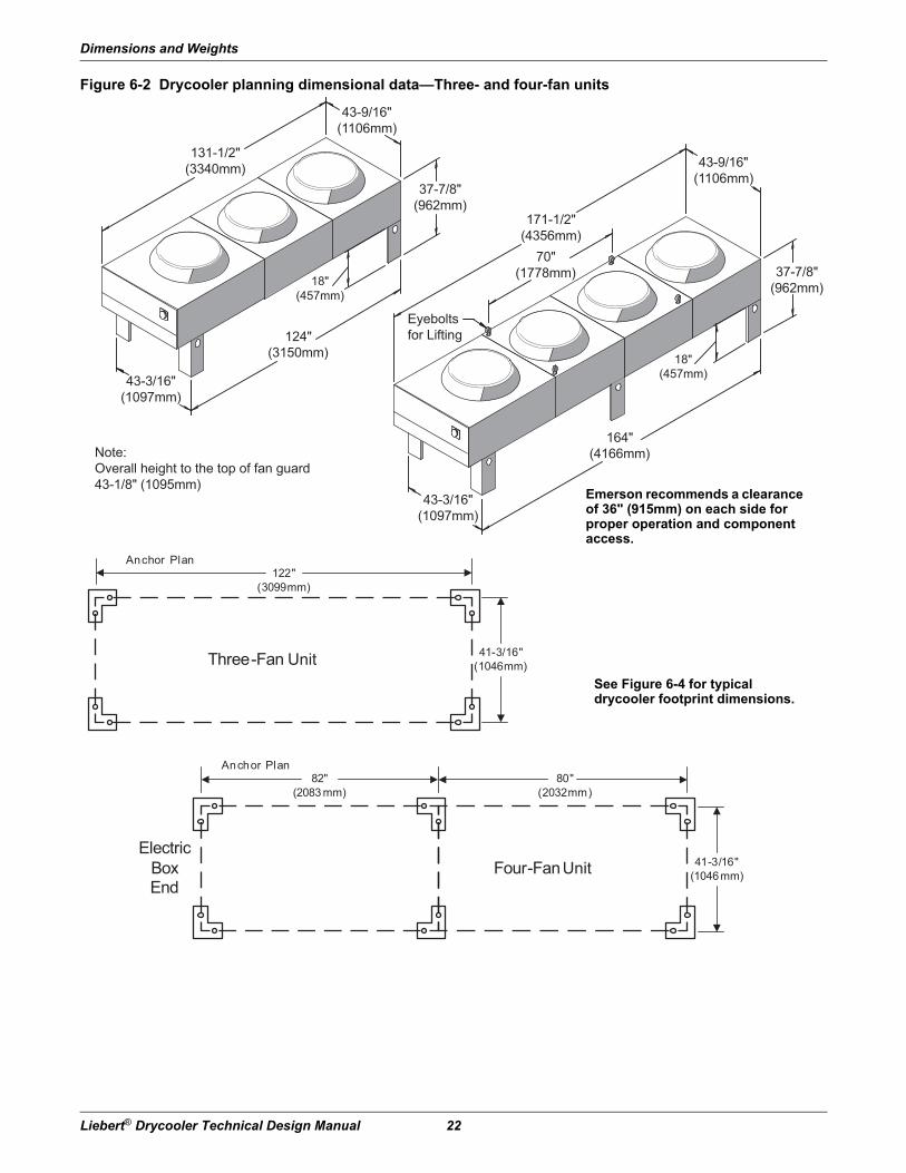
Figure 6-2 Drycooler planning dimensional data—Three- and four-fan units
Note:Overall height to the top of fan guard43-1/8" (1095mm)
Eyeboltsfor Lifting
37-7/8"(962mm)
37-7/8"(962mm)
171-1/2"(4356mm)
70"(1778mm)
131-1/2"(3340mm)
124"(3150mm)
164"(4166mm)
43-3/16"(1097mm)
43-3/16"(1097mm)
43-9/16"(1106mm)
43-9/16"(1106mm)
18"(457mm)
18"(457mm)
41-3/16"(1046mm)
122"(3099mm)
Three-Fan
Anchor Plan
41-3/16"(1046mm)
82"(2083 mm)
80"(2032mm)
Four-Fan Electric
BoxEnd
Anchor Plan
Unit
Unit
See Figure 6-4 for typical drycooler footprint dimensions.
Emerson recommends a clearance of 36" (915mm) on each side for proper operation and component access.

Dimensions and Weights
23 Liebert® Drycooler Technical Design Manual
Figure 6-3 Drycooler planning dimensional data—Six- and eight-fan units
171-1/2"(4356mm)37-7/8"
(962mm)
131-1/2"(3340mm)
18"(457mm)
70" (1778mm)
86-3/4"(2203mm)
86-3/4"(2203mm)
124"(3150mm)
164"(4166mm)
Overalll height to the topof the fan guard is 43-1/8” (1095mm).
1-1/2" (38mm)diameterhole for rigging(typ.4)
87-1/8"(2213mm)
87-1/8"(2213mm)
18"(457mm)
59"(1499mm)
37-7/8"(962mm)
Six-Fan
122"(3099mm)
84-3/4"(2153 mm)
Anchor Plan
Eight-Fan
82"(2083mm)
80"(2032mm)
84-3/4"(2153 mm)
ElectricBox End
Anchor Plan
Unit
Unit
See Figure 6-4 for typical drycooler footprint dimensions.
Emerson recommends a clearance of 36" (915mm) on each side for proper operation and component access.

Dimensions and Weights
Liebert® Drycooler Technical Design Manual 24
Figure 6-4 Typical drycooler footprint—dimensions
2”(50.8mm)
9/16" (14mm)Typical Diameter
1-3/4”(44.5mm)
4-1/4”(108mm)
1-3/4”(44.5mm)
4-1/4”(108mm)
1”(25.4mm)
2”(50.8mm)

Piping
25 Liebert® Drycooler Technical Design Manual
7.0 Piping
7.1 Piping Considerations
NOTICERisk of freezing temperatures and broken pipes. Can cause building and equipment damage.
When using water under pressure to test the system for leaks, immediately charge the tested system with glycol. Complete system drain-down cannot be assured.
Emerson recommends testing instead with common refrigerant gas pressurized with nitrogen and using a refrigerant-type leak detector to check for leaks.
Galvanized pipe or other components should not be used with an inhibited glycol system.
All fluid piping must comply with local codes. Care in sizing pipes will help reduce pumping power and operating costs.
Manual shutoff valves and unions should be installed at the supply and return line of each major system component. This permits routine service or emergency isolation of the component.
Where connecting to a city water supply, provide a disconnection means. A city water source is desirable for initially charging the system and as an emergency standby cooling source.
The minimum glycol temperature to be supplied from the drycooler determines whether the supply and return lines should be insulated to prevent condensation (see Table 10-1).
Vents are required at system high points to vent trapped air when filling the system.
Since the system is not open to the atmosphere, an expansion tank must be provided for expansion and contraction of the fluid with temperature change. A relief valve is also necessary.
A fill port is necessary for charging the system with glycol.
Depending on the complexity of the system, various other devices may be specified, such as pressure gages, valves, pumps and sensors.
7.2 Glycol/Inhibitor SolutionThe percentage of glycol to water will be determined by the outdoor ambient in which the system is operating. Just as critical is the inhibitor used with the glycol.
Commercial ethylene glycol (Union Carbide Ucartherm, Dow Chemical Dowtherm SR-1, and Texaco E.G. Heat Transfer Fluid 100), when pure, is generally less corrosive to the metals than water. It will, however, assume the corrosivity of the water from which it is prepared and may become increasingly corrosive with use if not properly inhibited. Proper inhibitor maintenance must be performed to prevent corrosion of the glycol system. Consult glycol manufacturer for testing and maintenance of inhibitors.
Automotive antifreeze is unacceptable and must not be used in any glycol fluid system.
There are two basic concepts of corrosion inhibition: They are classified as corrosion inhibitors or environmental stabilizers. The corrosion inhibitors function by forming a surface barrier that protects the metals. Environmental stabilizers decrease corrosion by stabilizing or favorably altering the overall environment. An alkaline buffer, such as borax, is a simple example, since its prime purpose is to maintain an alkaline condition (pH above 7).
The quality of the water of dilution must be considered because water may contain corrosive elements which reduce the effectiveness of the inhibited formulation. Surface waters that are classified as soft and are low in chloride and sulfate ion content (less than 100 ppm each) should be employed.

Piping
Liebert® Drycooler Technical Design Manual 26
7.3 Piping ConnectionsFigure 7-1 Piping connection locations for 1-, 2-, 3- and 4-fan drycoolers
Piping Connection Sizes (O.D. Cu)
Model No. No. of Coil CircuitsInlet and Outlet
Pipe Diameter, in.
-033 4* 1-3/8
-069 4, 8* 1-3/8
-092 6, 12*, 16 1-5/8
-109 8 1-3/8
-109 16* 2-1/8
-112 8 1-3/8
-112 16*, 26 2-1/8
-139 8, 16* 2-1/8
-174 8, 16*, 24 2-1/8
-197 8 1-3/8
-197 16*, 32 2-1/8
-225 16, 26* 2-1/8
-260 16, 24* 2-1/8
-310 16, 32* 2-1/8
-350 16, 32* 2-1/8
-350 48 2-5/8
-352 16, 24* 2-1/8
-419 16, 32* 2-1/8
-466 26 2-1/8
-466 40* 2-5/8
-491 16, 32 2-1/8
-491 48* 2-5/8
* = Standard Circuiting
INLET CONNECTION(UPPER HEADER)
OUTLET CONNECTION(LOWER HEADER)
EXPANSION TANK
1/2" FPTCONNECTIONS
DPN000275Pg. 1 Rev. 4
Piping
27 Liebert® Drycooler Technical Design Manual
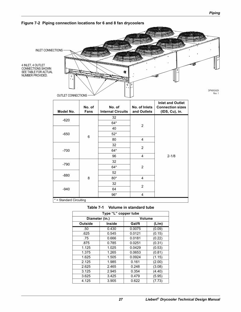
Figure 7-2 Piping connection locations for 6 and 8 fan drycoolers
Model No.No. of Fans
No. of Internal Circuits
No. of Inlets and Outlets
Inlet and Outlet Connection sizes
(IDS, Cu), in.
-620
6
32
2
2-1/8
64*
-650
40
52*
80 4
-700
322
64*
96 4
-790
8
32
264*
-88052
80* 4
-940
322
64
96* 4
* = Standard Circuiting
Table 7-1 Volume in standard tube
Type “L” copper tube
Diameter (in.) Volume
Outside Inside Gal/ft (L/m)
.50 0.430 0.0075 (0.09).625 0.545 0.0121 (0.15).75 0.666 0.0181 (0.22)
.875 0.785 0.0251 (0.31)1.125 1.025 0.0429 (0.53)1.375 1.265 0.0653 (0.81)1.625 1.505 0.0924 (1.15)2.125 1.985 0.161 (2.00)2.625 2.465 0.248 (3.08)3.125 2.945 0.354 (4.40)3.625 3.425 0.479 (5.95)4.125 3.905 0.622 (7.73)
INLET CONNECTIONS
OUTLET CONNECTIONS
4 INLET, 4 OUTLETCONNECTIONS SHOWNSEE TABLE FOR ACTUALNUMBER PROVIDED.
DPN002429Rev. 1
Piping
Liebert® Drycooler Technical Design Manual 28
Page intentionally left blank.

Pump Packages and Expansion Tank—Ancillary Items
29 Liebert® Drycooler Technical Design Manual
8.0 Pump Packagesand Expansion Tank—Ancillary Items
Figure 8-1 Pump curve, 60 Hz
Table 8-1 Pump piping and electrical data
HP
Connections
Hz
Electrical Data
Pump Suct.
Conn., in.Pump Disc. Conn., in.
FLA
PH208
Volts230
Volts460
Volts575
Volts
3/4
1-1/4 3/4
60
1 7.6 6.9 — —
3/4
3
3.5 3.2 1.6 1.3
1-1/2 6.6 6.0 3.0 2.4
2 7.5 6.8 3.4 2.7
31-1/2
1 10.6 9.6 4.8 3.9
5 1-1/4 16.7 15.2 7.6 6.1
7-1/2 3 3 24.2 22.0 11.0 9.0
200 Volts
220 Volts
380/415 Volts
1
1-1/4 3/4
50 3
3.26 3.24 1.64 / 1.63
1-1/2 4.51 4.47 2.4 / 2.25
2 5.77 5.71 3.00 / 2.88
31-1/2
1-1/4 8.76 8.67 4.7 / 4.38
5 1 14.94 14.5 7.9 / 7.47
0
100
120
80
160
180
140
60
40
2020 30 5010 120 2007040 60 80 160 250 300 400
G
A
B
C
D
E
F
Tota
l Hea
d, F
eet/W
ater
Curve
Flow Rate, GPM
HP
3/4 (1-ph)3/4 (3-ph)
1.5235
7.5
ABCDEF
G
Pump Packages and Expansion Tank—Ancillary Items
Liebert® Drycooler Technical Design Manual 30
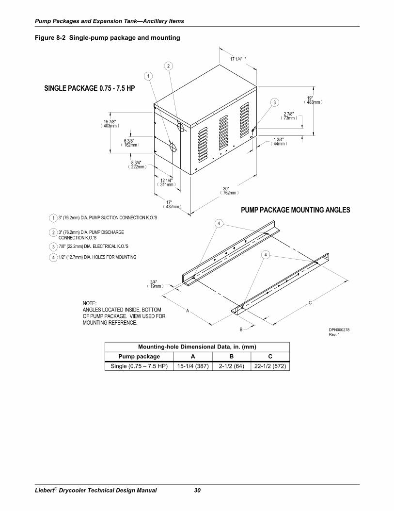
Figure 8-2 Single-pump package and mounting
Mounting-hole Dimensional Data, in. (mm)
Pump package A B C
Single (0.75 – 7.5 HP) 15-1/4 (387) 2-1/2 (64) 22-1/2 (572)
19"483mm
2 7/8"73mm
3
1 3/4"44mm
30"762mm
17"432mm
12 1/4"311mm
6 3/8"162mm
15 7/8"403mm
2
1
SINGLE PACKAGE 0.75 - 7.5 HP
1
2
3
4
3" (76.2mm) DIA. PUMP SUCTION CONNECTION K.O.'S
3" (76.2mm) DIA. PUMP DISCHARGECONNECTION K.O.'S
7/8" (22.2mm) DIA. ELECTRICAL K.O.'S
1/2" (12.7mm) DIA. HOLES FOR MOUNTING
8 3/4"222mm
17 1/4" "
A
3/4"19mm
4
4
PUMP PACKAGE MOUNTING ANGLES
NOTE:ANGLES LOCATED INSIDE, BOTTOMOF PUMP PACKAGE. VIEW USED FORMOUNTING REFERENCE.
B
C
DPN000278Rev. 1

Pump Packages and Expansion Tank—Ancillary Items
31 Liebert® Drycooler Technical Design Manual
Figure 8-3 Dual-pump package and mounting
Mounting-hole Dimensional Data, in. (mm)
Pump package A B C
Dual (0.75 – 5.0 HP) 30-1/4 (768) 2-1/2 (64) 22-1/2 (572)
Dual (7.5 HP) 39-5/16 (999) 1-3/4 (45) 26-7/8 (683)
19"483mm
1 3/4"44mm
30"762mm
8 3/4"222mm12 1/4"311mm
23 3/4"603mm27 1/4"692mm
32"813mm
6 3/8"162mm
15 7/8"403mm
3
3
2
2
1
1
DUAL PACKAGE 0.75 - 5 HP1
2
3
3" (76.2mm) DIA. PUMP SUCTION CONNECTION K.O.'S
3" (76.2mm) DIA. PUMP DISCHARGECONNECTION K.O.'S
7/8" (22.2mm) DIA. ELECTRICAL K.O.'S
4
5
5" (127mm) DIA. PUMP DISCHARGECONNECTION HOLE
5" (127mm) DIA. PUMP SUCTIONCONNECTION HOLE
5 54
4
3DUAL PACKAGE 7.5 HP
32 1/4"819mm
2 7/8"73mm
4 1/8"105mm
33 3/16"843mm
29 3/16"741mm
15 7/8"403mm
11 7/8"302mm
16 3/8"416mm
6 1/2"165mm
41"1041mm
41 1/4"1048mm
32 3/8"822mm
19 5/16"491mm
6 1/2" (12.7mm) DIA. HOLES FORMOUNTING
A
3/4"19mm
6
6
PUMP PACKAGE MOUNTING ANGLES
NOTE:ANGLES LOCATED INSIDE, BOTTOMOF PUMP PACKAGE. VIEW USED FORMOUNTING REFERENCE.
B
C
DPN000328Pg. 1 Rev. 1

Pump Packages and Expansion Tank—Ancillary Items
Liebert® Drycooler Technical Design Manual 32
Expansion TankThis tank, included in a standard pump package, has an internal volume of 8.8 gal. (33 l) and a maximum pressure of 100 psi (690 kPa).
This tank is sized for a typical “open” system with a fluid volume of less than 75 gal. (280l). When used in a “closed” system, volumes of up to 140 gal. (530 l) can be accommodated. The use of a safety relief valve, field supplied, is recommended for systems “closed” to atmospheric venting. Other piping accessories for filling, venting, or adjusting the fluid in the system, are recommended, but not included.
Figure 8-4 Expansion tank
EXPANSION TANK
8.8 GALLON EXPANSION TANK(33.3 Liter)
9"229mm
2 3/4"70mm
6 1/8"156mm
1/2" FPTFITTING
30 1/2"775mm
4"102mm
3"76mm TYP.
1 1/2"38mm TYP.
17 1/4"438mm TYP.
1/2"13mm TYP. (8) PLACES
7"178mm
6 13/16"173mm
1/2" FPTFITTING
DPN000329Rev. 1

Electrical Data
33 Liebert® Drycooler Technical Design Manual
9.0 Electrical DataElectrical service is required for all drycoolers at the location of the outdoor system. The power supply does not necessarily have to be the same voltage supply that is required by the indoor unit. The only electrical connection between the indoor unit and the drycooler is a two-wire control interlock, which is field-provided and field-connected.
Tables 9-1, 9-2 and 9-3 provide electrical requirements for drycoolers and pumps powered from separate power supplies. Tables 9-4 and 9-5 provide single electrical-supply requirements of drycoolers using integral pump controls.
9.1 Line Voltage Electrical DataTable 9-1 60Hz electrical values—Drycoolers without pump controls
# of Fans Model # Voltage Phase FLA WSA OPD
Standard Models
1 33, 69, 92, 109, 112208/230
1 4.8 6.0 153 3.5 4.4 15
460 3 1.7 2.1 15575 3 1.4 1.8 15
2 139, 174, 197, 225208/230 3 7.0 7.9 15
460 3 3.4 3.8 15575 3 2.8 3.2 15
3 260, 310, 350208/230 3 10.5 11.4 15
460 3 5.1 5.5 15575 3 4.2 4.6 15
4 352, 419, 466, 491208/230 3 14.0 14.9 20
460 3 6.8 7.2 15575 3 5.6 6.0 15
6 620, 650, 700208/230 3 21.0 21.9 25
460 3 10.2 10.6 15575 3 8.4 8.8 15
8 790, 880, 940208/230 3 28.0 28.9 35
460 3 13.6 14.0 20575 3 11.2 11.6 15
Liebert Quiet-Line Models
1 40, 57, 60208/230 3 1.8 2.3 15
460 3 0.9 1.1 15575 3 0.7 0.9 15
2 80, 111, 121208/230 3 3.6 4.1 15
460 3 1.8 2.0 15575 3 1.4 1.6 15
3 158, 173, 178208/230 3 5.4 5.9 15
460 3 2.7 2.9 15575 3 2.1 2.3 15
4 205, 248208/230 3 7.2 7.7 15
460 3 3.6 3.8 15575 3 2.8 3.0 15
6 347, 356208/230 3 10.8 11.3 15
460 3 5.4 5.6 15575 3 4.2 4.4 15
8 453, 498208/230 3 14.4 14.9 20
460 3 7.2 7.4 15575 3 5.6 5.8 15
Values are calculated per UL 1995. OPD values may be adjusted higher than calculations to compensate for maximum anticipated application temperatures.
Electrical Data
Liebert® Drycooler Technical Design Manual 34
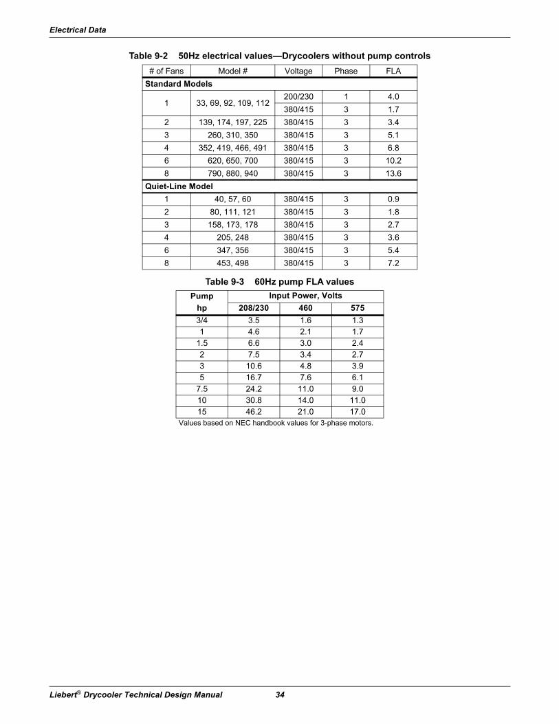
Table 9-2 50Hz electrical values—Drycoolers without pump controls
# of Fans Model # Voltage Phase FLA
Standard Models
1 33, 69, 92, 109, 112200/230 1 4.0
380/415 3 1.7
2 139, 174, 197, 225 380/415 3 3.4
3 260, 310, 350 380/415 3 5.1
4 352, 419, 466, 491 380/415 3 6.8
6 620, 650, 700 380/415 3 10.2
8 790, 880, 940 380/415 3 13.6
Quiet-Line Model
1 40, 57, 60 380/415 3 0.9
2 80, 111, 121 380/415 3 1.8
3 158, 173, 178 380/415 3 2.7
4 205, 248 380/415 3 3.6
6 347, 356 380/415 3 5.4
8 453, 498 380/415 3 7.2
Table 9-3 60Hz pump FLA values
Pump
hp
Input Power, Volts
208/230 460 575
3/4 3.5 1.6 1.31 4.6 2.1 1.7
1.5 6.6 3.0 2.42 7.5 3.4 2.73 10.6 4.8 3.95 16.7 7.6 6.1
7.5 24.2 11.0 9.010 30.8 14.0 11.015 46.2 21.0 17.0
Values based on NEC handbook values for 3-phase motors.

Electrical Data
35 Liebert® Drycooler Technical Design Manual
Table 9-4 60Hz Electrical values—Standard drycoolers with integral pump controls
# ofFans 1 2 3 4 6 8
Model# 33,69,92,109,112 139,174,197,225 260,310,350 352,419,466,491 620,650,700 790,880,940
Pumphp Ph FLA WSA OPD Ph FLA WSA OPD Ph FLA WSA OPD Ph FLA WSA OPD Ph FLA WSA OPD Ph FLA WSA OPD
208/230/60
0.75 1 12.4 14.3 20 — — — — — — — — — — — — — — — — — — — —
0.75 3 7.0 7.9 15 3 10.5 11.4 15 3 14.0 14.9 20 3 17.5 18.4 25 3 24.5 25.4 30 3 31.5 32.4 40
1.5 3 10.1 11.8 15 3 13.6 15.3 20 3 17.1 18.8 25 3 20.6 22.3 25 3 27.6 29.3 35 3 34.6 36.3 40
2.0 3 11.0 12.9 20 3 14.5 16.4 20 3 18.0 19.9 25 3 21.5 23.4 30 3 28.5 30.4 35 3 35.5 37.4 45
3.0 3 14.1 16.8 25 3 17.6 20.3 30 3 21.1 23.8 30 3 24.6 27.3 35 3 31.6 34.3 40 3 38.6 41.3 50
5.0 3 20.2 24.4 40 3 23.7 27.9 40 3 27.2 31.4 45 3 30.7 34.9 50 3 37.7 41.9 50 3 44.7 48.9 60
7.5 * 3 27.7 33.8 50 3 31.2 37.3 60 3 34.7 40.8 60 3 38.2 44.3 60 3 45.2 51.3 70 3 52.2 58.3 80
10.0 * 3 34.3 42.0 70 3 37.8 45.5 70 3 41.3 49.0 70 3 44.8 52.5 80 3 51.8 59.5 90 3 58.8 66.5 90
15 * 3 49.7 61.3 100 3 53.2 64.8 110 3 56.7 68.3 110 3 60.2 71.8 110 3 67.2 78.8 110 3 74.2 85.8 125
460/60
0.75 3 3.3 3.7 15 3 5.0 5.4 15 3 6.7 7.1 15 3 8.4 8.8 15 3 11.8 12.2 15 3 15.2 15.6 20
1.5 3 4.7 5.5 15 3 6.4 7.2 15 3 8.1 8.9 15 3 9.8 10.6 15 3 13.2 14.0 20 3 16.6 17.4 20
2.0 3 5.1 6.0 15 3 6.8 7.7 15 3 8.5 9.4 15 3 10.2 11.1 15 3 13.6 14.5 20 3 17.0 17.9 20
3.0 3 6.5 7.7 15 3 8.2 9.4 15 3 9.9 11.1 15 3 11.6 12.8 15 3 15.0 16.2 20 3 18.4 19.6 25
5.0 3 9.3 11.2 15 3 11.0 12.9 20 3 12.7 14.6 20 3 14.4 16.3 20 3 17.8 19.7 25 3 21.2 23.1 30
7.5 3 12.7 15.5 25 3 14.4 17.2 25 3 16.1 18.9 25 3 17.8 20.6 30 3 21.2 24.0 30 3 24.6 27.4 35
10.0 3 15.7 19.2 30 3 17.4 20.9 30 3 19.1 22.6 35 3 20.8 24.3 35 3 24.2 27.7 40 3 27.6 31.1 45
15 * 3 22.7 28.0 45 3 24.4 29.7 50 3 26.1 31.4 50 3 27.8 33.1 50 3 31.2 36.5 50 3 34.6 39.9 60
575/60
0.75 3 2.7 3.1 15 3 4.1 4.5 15 3 5.5 5.9 15 3 6.9 7.3 15 3 9.7 10.1 15 3 12.5 12.9 15
1.5 3 3.8 4.4 15 3 5.2 5.8 15 3 6.6 7.2 15 3 8.0 8.6 15 3 10.8 11.4 15 3 13.6 14.2 20
2.0 3 4.1 4.8 15 3 5.5 6.2 15 3 6.9 7.6 15 3 8.3 9.0 15 3 11.1 11.8 15 3 13.9 14.6 20
3.0 3 5.3 6.3 15 3 6.7 7.7 15 3 8.1 9.1 15 3 9.5 10.5 15 3 12.3 13.3 15 3 15.1 16.1 20
5.0 3 7.5 9.0 15 3 8.9 10.4 15 3 10.3 11.8 15 3 11.7 13.2 15 3 14.5 16.0 20 3 17.3 18.8 20
7.5 3 10.4 12.7 20 3 11.8 14.1 20 3 13.2 15.5 20 3 14.6 16.9 25 3 17.4 19.7 25 3 20.2 22.5 30
10.0 3 12.4 15.2 25 3 13.8 16.6 25 3 15.2 18.0 25 3 16.6 19.4 30 3 19.4 22.2 30 3 22.2 25.0 35
15 3 18.4 22.7 35 3 19.8 24.1 40 3 21.2 25.5 40 3 22.6 26.9 40 3 25.4 29.7 45 3 28.2 32.5 45
Values are calculated per UL 1995. Pump FLA values used are based on NEC tables for motor horsepower. OPD values may be adjusted higher than calculations to compensate for maximum anticipated application temperatures.
* May require electrical component(s) with higher capacity in the drycooler. Consult factory representatives for assistance before ordering.

Electrical Data
Liebert® Drycooler Technical Design Manual 36
Table 9-5 60 Hz Electrical values - Liebert Quiet-Line drycoolers with integral pump controls
# ofFans 1 2 3 4 6 8
Model# 40,57,60 80,111,121 158,173,178 205,248 347,356 453,498
Pumphp Ph FLA WSA OPD Ph FLA WSA OPD Ph FLA WSA OPD Ph FLA WSA OPD Ph FLA WSA OPD Ph FLA WSA OPD
208/230/3/60
0.75 3 5.3 6.2 15 3 7.1 8.0 15 3 8.9 9.8 15 3 10.7 11.6 15 3 14.3 15.2 20 3 17.9 18.8 25
1.5 3 8.4 10.1 15 3 10.2 11.9 15 3 12.0 13.7 20 3 13.8 15.5 20 3 17.4 19.1 25 3 21.0 22.7 25
2.0 3 9.3 11.2 15 3 11.1 13.0 20 3 12.9 14.8 20 3 14.7 16.6 20 3 18.3 20.2 25 3 21.9 23.8 30
3.0 3 12.4 15.1 25 3 14.2 16.9 25 3 16.0 18.7 25 3 17.8 20.5 30 3 21.4 24.1 30 3 25.0 27.7 35
5.0 3 18.5 22.7 35 3 20.3 24.5 40 3 22.1 26.3 40 3 23.9 28.1 40 3 27.5 31.7 45 3 31.1 35.3 50
7.5 * 3 26.0 32.1 50 3 27.8 33.9 50 3 29.6 35.7 50 3 31.4 37.5 60 3 35.0 41.1 60 3 38.6 44.7 60
10.0 * 3 32.6 40.3 70 3 34.4 42.1 70 3 36.2 43.9 70 3 38.0 45.7 70 3 41.6 49.3 80 3 45.2 52.9 80
15 * 3 48.0 59.6 100 3 49.8 61.4 100 3 51.6 63.2 100 3 53.4 65.0 110 3 57.0 68.6 110 3 60.6 72.2 110
460/3/60
0.75 3 2.5 2.9 15 3 3.4 3.8 15 3 4.3 4.7 15 3 5.2 5.6 15 3 7.0 7.4 15 3 8.8 9.2 15
1.5 3 3.9 4.7 15 3 4.8 5.6 15 3 5.7 6.5 15 3 6.6 7.4 15 3 8.4 9.2 15 3 10.2 11.0 15
2.0 3 4.3 5.2 15 3 5.2 6.1 15 3 6.1 7.0 15 3 7.0 7.9 15 3 8.8 9.7 15 3 10.6 11.5 15
3.0 3 5.7 6.9 15 3 6.6 7.8 15 3 7.5 8.7 15 3 8.4 9.6 15 3 10.2 11.4 15 3 12.0 13.2 15
5.0 3 8.5 10.4 15 3 9.4 11.3 15 3 10.3 12.2 15 3 11.2 13.1 20 3 13.0 14.9 20 3 14.8 16.7 20
7.5 3 11.9 14.7 25 3 12.8 15.6 25 3 13.7 16.5 25 3 14.6 17.4 25 3 16.4 19.2 30 3 18.2 21.0 30
10.0 3 14.9 18.4 30 3 15.8 19.3 30 3 16.7 20.2 30 3 17.6 21.1 35 3 19.4 22.9 35 3 21.2 24.7 35
15 * 3 21.9 27.2 45 3 22.8 28.1 45 3 23.7 29.0 45 3 24.6 29.9 50 3 26.4 31.7 50 3 28.2 33.5 50
575/3/60
0.75 3 2.0 2.3 15 3 2.7 3.0 15 3 3.4 3.7 15 3 4.1 4.4 15 3 5.5 5.8 15 3 6.9 7.2 15
1.5 3 3.1 3.7 15 3 3.8 4.4 15 3 4.5 5.1 15 3 5.2 5.8 15 3 6.6 7.2 15 3 8.0 8.6 15
2.0 3 3.4 4.1 15 3 4.1 4.8 15 3 4.8 5.5 15 3 5.5 6.2 15 3 6.9 7.6 15 3 8.3 9.0 15
3.0 3 4.6 5.6 15 3 5.3 6.3 15 3 6.0 7.0 15 3 6.7 7.7 15 3 8.1 9.1 15 3 9.5 10.5 15
5.0 3 6.8 8.3 15 3 7.5 9.0 15 3 8.2 9.7 15 3 8.9 10.4 15 3 10.3 11.8 15 3 11.7 13.2 15
7.5 3 9.7 12.0 20 3 10.4 12.7 20 3 11.1 13.4 20 3 11.8 14.1 20 3 13.2 15.5 20 3 14.6 16.9 25
10.0 3 11.7 14.5 25 3 12.4 15.2 25 3 13.1 15.9 25 3 13.8 16.6 25 3 15.2 18.0 25 3 16.6 19.4 30
15 3 17.7 22.0 35 3 18.4 22.7 35 3 19.1 23.4 40 3 19.8 24.1 40 3 21.2 25.5 40 3 22.6 26.9 40
Values are calculated per UL 1995. Pump FLA values used are based on NEC tables for motor horsepower. OPD values may be adjusted higher than calculations to compensate for maximum anticipated application temperatures.
* May require electrical component(s) with higher capacity in the drycooler. Consult factory representatives for assistance before ordering.
Electrical Data
37 Liebert® Drycooler Technical Design Manual
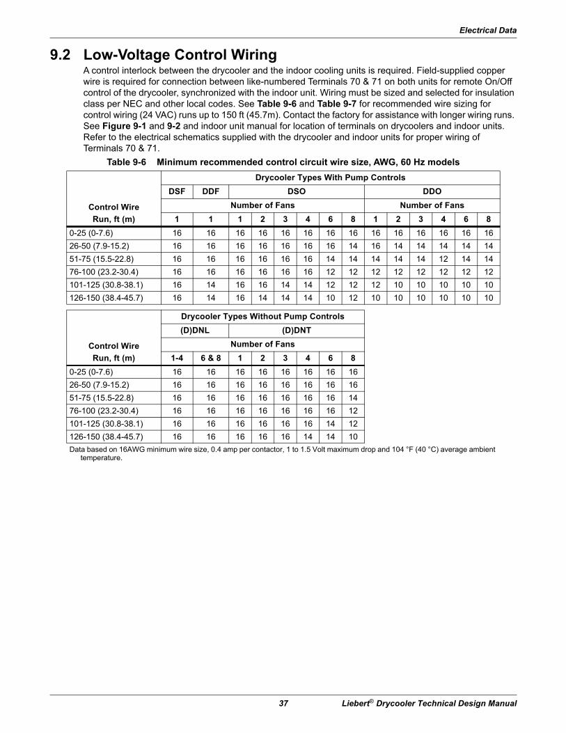
9.2 Low-Voltage Control WiringA control interlock between the drycooler and the indoor cooling units is required. Field-supplied copper wire is required for connection between like-numbered Terminals 70 & 71 on both units for remote On/Off control of the drycooler, synchronized with the indoor unit. Wiring must be sized and selected for insulation class per NEC and other local codes. See Table 9-6 and Table 9-7 for recommended wire sizing for control wiring (24 VAC) runs up to 150 ft (45.7m). Contact the factory for assistance with longer wiring runs. See Figure 9-1 and 9-2 and indoor unit manual for location of terminals on drycoolers and indoor units. Refer to the electrical schematics supplied with the drycooler and indoor units for proper wiring of Terminals 70 & 71.
Table 9-6 Minimum recommended control circuit wire size, AWG, 60 Hz models
Control Wire
Run, ft (m)
Drycooler Types With Pump Controls
DSF DDF DSO DDO
Number of Fans Number of Fans
1 1 1 2 3 4 6 8 1 2 3 4 6 8
0-25 (0-7.6) 16 16 16 16 16 16 16 16 16 16 16 16 16 16
26-50 (7.9-15.2) 16 16 16 16 16 16 16 14 16 14 14 14 14 14
51-75 (15.5-22.8) 16 16 16 16 16 16 14 14 14 14 14 12 14 14
76-100 (23.2-30.4) 16 16 16 16 16 16 12 12 12 12 12 12 12 12
101-125 (30.8-38.1) 16 14 16 16 14 14 12 12 12 10 10 10 10 10
126-150 (38.4-45.7) 16 14 16 14 14 14 10 12 10 10 10 10 10 10
Control Wire
Run, ft (m)
Drycooler Types Without Pump Controls
(D)DNL (D)DNT
Number of Fans
1-4 6 & 8 1 2 3 4 6 8
0-25 (0-7.6) 16 16 16 16 16 16 16 16
26-50 (7.9-15.2) 16 16 16 16 16 16 16 16
51-75 (15.5-22.8) 16 16 16 16 16 16 16 14
76-100 (23.2-30.4) 16 16 16 16 16 16 16 12
101-125 (30.8-38.1) 16 16 16 16 16 16 14 12
126-150 (38.4-45.7) 16 16 16 16 16 14 14 10
Data based on 16AWG minimum wire size, 0.4 amp per contactor, 1 to 1.5 Volt maximum drop and 104 °F (40 °C) average ambient temperature.
Electrical Data
Liebert® Drycooler Technical Design Manual 38
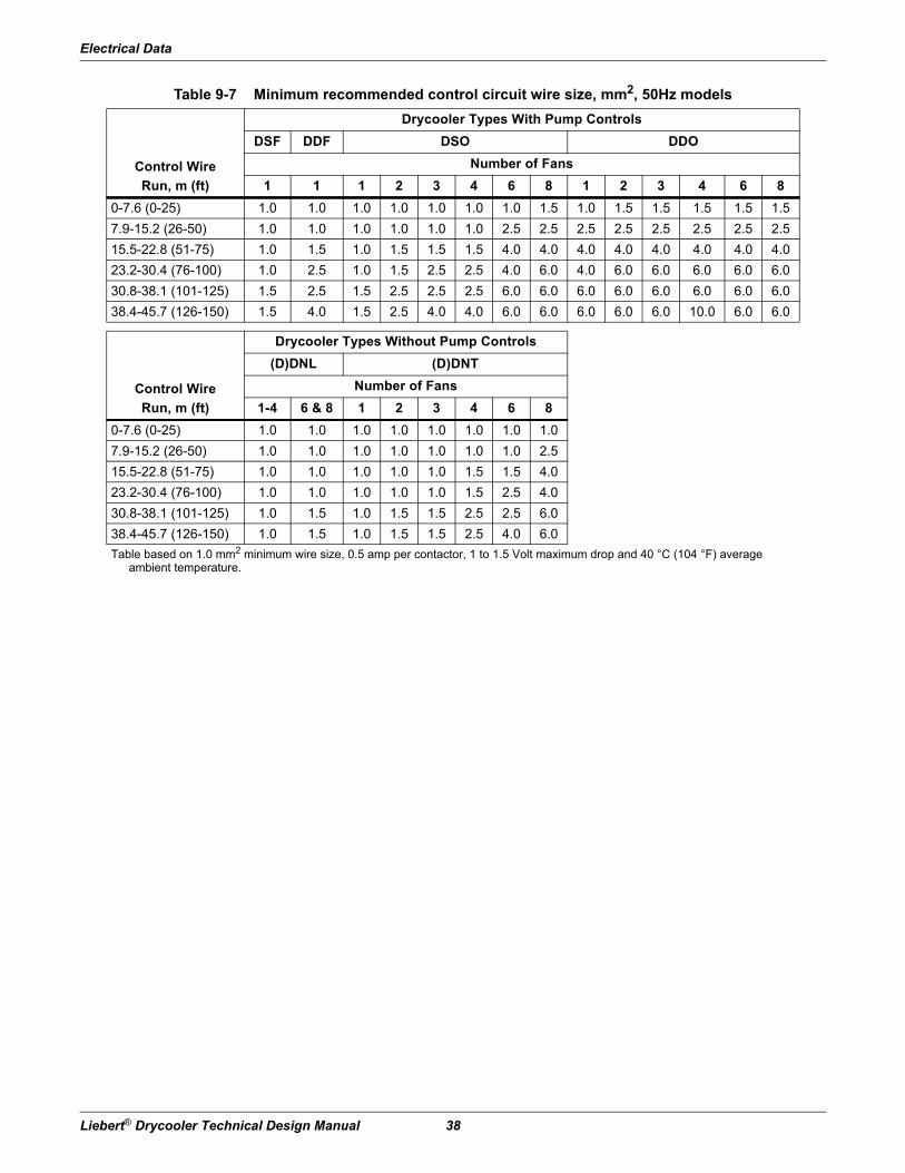
Table 9-7 Minimum recommended control circuit wire size, mm2, 50Hz models
Control Wire
Run, m (ft)
Drycooler Types With Pump Controls
DSF DDF DSO DDO
Number of Fans
1 1 1 2 3 4 6 8 1 2 3 4 6 8
0-7.6 (0-25) 1.0 1.0 1.0 1.0 1.0 1.0 1.0 1.5 1.0 1.5 1.5 1.5 1.5 1.5
7.9-15.2 (26-50) 1.0 1.0 1.0 1.0 1.0 1.0 2.5 2.5 2.5 2.5 2.5 2.5 2.5 2.5
15.5-22.8 (51-75) 1.0 1.5 1.0 1.5 1.5 1.5 4.0 4.0 4.0 4.0 4.0 4.0 4.0 4.0
23.2-30.4 (76-100) 1.0 2.5 1.0 1.5 2.5 2.5 4.0 6.0 4.0 6.0 6.0 6.0 6.0 6.0
30.8-38.1 (101-125) 1.5 2.5 1.5 2.5 2.5 2.5 6.0 6.0 6.0 6.0 6.0 6.0 6.0 6.0
38.4-45.7 (126-150) 1.5 4.0 1.5 2.5 4.0 4.0 6.0 6.0 6.0 6.0 6.0 10.0 6.0 6.0
Control Wire
Run, m (ft)
Drycooler Types Without Pump Controls
(D)DNL (D)DNT
Number of Fans
1-4 6 & 8 1 2 3 4 6 8
0-7.6 (0-25) 1.0 1.0 1.0 1.0 1.0 1.0 1.0 1.0
7.9-15.2 (26-50) 1.0 1.0 1.0 1.0 1.0 1.0 1.0 2.5
15.5-22.8 (51-75) 1.0 1.0 1.0 1.0 1.0 1.5 1.5 4.0
23.2-30.4 (76-100) 1.0 1.0 1.0 1.0 1.0 1.5 2.5 4.0
30.8-38.1 (101-125) 1.0 1.5 1.0 1.5 1.5 2.5 2.5 6.0
38.4-45.7 (126-150) 1.0 1.5 1.0 1.5 1.5 2.5 4.0 6.0
Table based on 1.0 mm2 minimum wire size, 0.5 amp per contactor, 1 to 1.5 Volt maximum drop and 40 °C (104 °F) average ambient temperature.

Electrical Data
39 Liebert® Drycooler Technical Design Manual
9.3 Electrical Connection DiagramsFigure 9-1 Electrical field connections, 1-fan DSF/DDF drycooler with pump control
70 71
Factory wired to 24VClass 2 control circuit Factory wired to components
on electric panelElectric service connectionto fuse block (factory wired) Electric service connection
terminals for field wiring
Factory installeddisconnect switch
Note:Refer to specification sheet forfull load amp and wire sizeamp ratings
Control interlock field suppliedClass 2 wiring to interlockdrycooler 24V controls toLiebert room unit. 7/8" (22mm)diameter hole provided inbottom of electric box
Electric service connection terminalsfor power supply to pumps whenpump controls are factory supplied.7/8" (22mm) diameter knockoutsprovided in bottom of electric box.Three terminals for three phasepump option only
Earth ground bar (50Hz).Connection terminals with factory
ground from each high voltagecomponent for field supplied
earth grounding wire.
PUMP FUSES & OVERLOADHEATERS (SHIPPED WITHSTANDARD PUMP PACKAGES)ARE TO BE FIELD INSTALLEDIN PUMP FUSE BLOCK(S) ANDSTARTER(S).
Earth ground connection (60Hz).Connection terminal for fieldsupplied earth grounding wire Electric service entrance.
A 7/8" (22mm) diameter holein a 1-1/8" (29mm) knockout
provided in bottom of electric boxElectric service single phasenot by Liebert. Three phasenot by Liebert (for three phasepump option only)
DPN000277Pg. 1 Rev. 2

Electrical Data
Liebert® Drycooler Technical Design Manual 40
Figure 9-2 Electrical field connections, 1-, 2-, 3- and 4-fan DSO/DDO drycooler with pump control
24 50 70 71 77 74
Factory wired to 24VClass 2 control circuit
Unit Alarm ConnectionField supplied 24VClass 2 wiring toterminals 24 & 50 toindicate "StandbyGlycol Pump On".(Supplied with dualpump controls only).
Factory wired to componentson electric panel
Electrical service connection terminalswhen factory disconnect is not supplied.Fuse block supplied on DNT drycoolers.
Electrical service connection terminalswhen factory disconnect is supplied.
Factory installeddisconnect switch(optional)
Electric service notprovided by Liebert.Electric service entrance.
A 7/8" (22mm) diameter holein a 1-1/8" (29mm) knockout
provided in bottom of electric box.
Earth ground connection (60Hz).Connection terminal for fieldsupplied earth ground wire.
Earth ground bar (50Hz).Connection terminals with factoryground from each high voltagecomponent for field suppliedearth ground wire.
PUMP FUSES & OVERLOADHEATERS (SHIPPED WITHSTANDARD PUMP PACKAGES)ARE TO BE FIELD INSTALLEDIN PUMP FUSE BLOCK(S) ANDSTARTER(S).
Electric service connection terminals forpower supply to pumps when pump controlsare factory supplied. Dual pump connectionshown. 7/8" (22mm) diameter knockoutsprovided in bottom of electric box.
Flow switch connection(Dual pump controls only).Field supplied 24V Class 2wiring from terminals 74 & 77to field mounted flow switch.
Control interlock. Field suppliedClass 2 wiring to interlock
drycooler 24V controls to Liebertroom unit. 7/8" (22mm) diameter
hole provided in bottom ofelectric box.
Note:Refer to specification sheetfor full load amp and wiresize amp ratings.
DPN000276Rev. 2
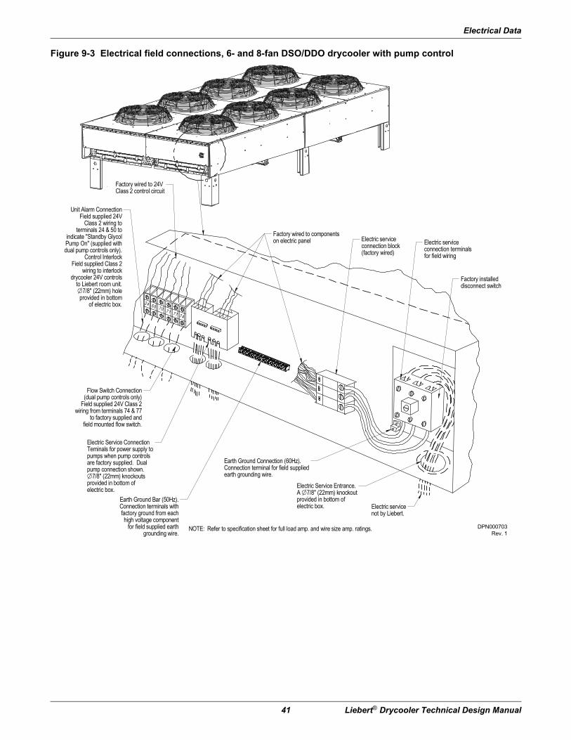
Electrical Data
41 Liebert® Drycooler Technical Design Manual
Figure 9-3 Electrical field connections, 6- and 8-fan DSO/DDO drycooler with pump control
NOTE: Refer to specification sheet for full load amp. and wire size amp. ratings.
24 50 70 71 77 74
Factory wired to 24VClass 2 control circuit
Unit Alarm ConnectionField supplied 24V
Class 2 wiring toterminals 24 & 50 to
indicate "Standby GlycolPump On" (supplied withdual pump controls only).
Control InterlockField supplied Class 2
wiring to interlockdrycooler 24V controls
to Liebert room unit.7/8" (22mm) hole
provided in bottomof electric box.
Flow Switch Connection(dual pump controls only)
Field supplied 24V Class 2wiring from terminals 74 & 77
to factory supplied andfield mounted flow switch.
Electric Service ConnectionTeminals for power supply topumps when pump controlsare factory supplied. Dualpump connection shown.
7/8" (22mm) knockoutsprovided in bottom ofelectric box.
Earth Ground Bar (50Hz).Connection terminals withfactory ground from eachhigh voltage component
for field supplied earthgrounding wire.
Earth Ground Connection (60Hz).Connection terminal for field suppliedearth grounding wire.
Electric Service Entrance.A 7/8" (22mm) knockoutprovided in bottom ofelectric box. Electric service
not by Liebert.
Factory installeddisconnect switch
Electric serviceconnection terminalsfor field wiring
Electric serviceconnection block(factory wired)
Factory wired to componentson electric panel
DPN000703Rev. 1

Electrical Data
Liebert® Drycooler Technical Design Manual 42
Figure 9-4 Electrical field connections, 6- and 8-fan DDNC drycooler without pump control
NOTE: Refer to specification sheet for full load amp. and wire size amp. ratings.
Factory wireddirectly tofan motors
Earth ground connection (60Hz)Connection terminal for fieldsupplied earth grounding wirewhen factory disconnect is NOTsupplied.
Factory supplied wiringwhen (optional) disconnectswitch is ordered
Electric service connectionterminals when factorydisconnect is NOT supplied
Electric service connectionterminals when factorydisconnect is supplied
Factory installeddisconnect switch(optional)
Electric service entranceA 7/8" (22mm) hole in a1-1/8" (29mm) knockoutprovided in bottom ofelectric panel
Electric service not by Liebert.Three phase for all models.Provide in accordance withlocal and national electric code
DPN000702Rev. 1

Electrical Data
43 Liebert® Drycooler Technical Design Manual
Figure 9-5 Electrical field connections, 6- and 8-fan DDNL/DDNT drycooler without pump control
NOTE: Refer to specification sheet for full load amp. and wire size amp. ratings.
Electric Service Connectionand fuse block
Factory wired to 24VClass 2 control circuit
Control InterlockField supplied Class 2
wiring to interlockcondenser 24V controls
to Liebert room unit.7/8" (22mm) hole
provided in bottom ofelectric box
Factory wired to componentson electric panel
Earth Ground Bar (optional on 50Hz only).Connection terminals with factory groundfrom each high voltage component forfield supplied earth grounding wire
Earth Ground Connection (60Hz).Connection terminal for field suppliedearth grounding wire when factory disconnect is NOT supplied
Electric Service.Three phase forall models. Wiringnot by Liebert
Electric Service Entrance.A 7/8" (22mm) hole ina 1-1/8" (29mm) knockoutprovided in bottom ofelectric box
Factory installed disconnect switch(optional)
Electric Service Connectionterminals when factorydisconnect is supplied
Electric Service Connectionterminals when factorydisconnect is NOT supplied
DPN000704Rev. 1
Electrical Data
Liebert® Drycooler Technical Design Manual 44
Page intentionally left blank.
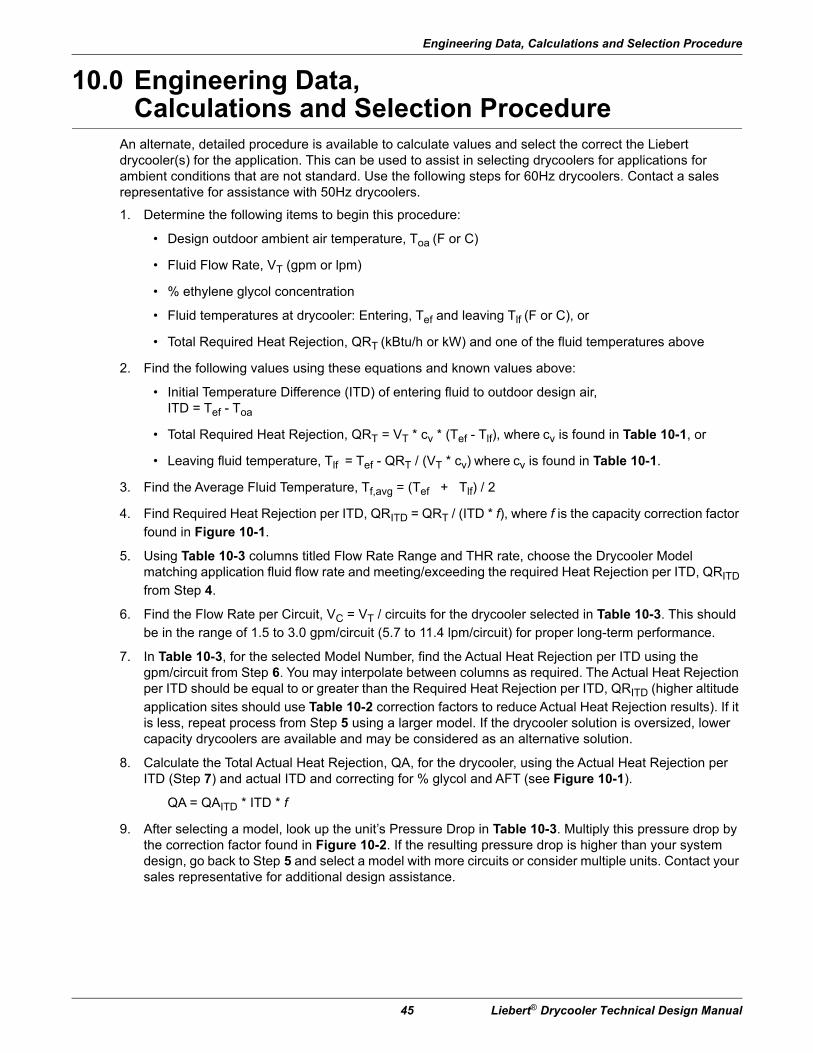
Engineering Data, Calculations and Selection Procedure
45 Liebert® Drycooler Technical Design Manual
10.0 Engineering Data, Calculations and Selection Procedure
An alternate, detailed procedure is available to calculate values and select the correct the Liebert drycooler(s) for the application. This can be used to assist in selecting drycoolers for applications for ambient conditions that are not standard. Use the following steps for 60Hz drycoolers. Contact a sales representative for assistance with 50Hz drycoolers.
1. Determine the following items to begin this procedure:
• Design outdoor ambient air temperature, Toa (F or C)
• Fluid Flow Rate, VT (gpm or lpm)
• % ethylene glycol concentration
• Fluid temperatures at drycooler: Entering, Tef and leaving Tlf (F or C), or
• Total Required Heat Rejection, QRT (kBtu/h or kW) and one of the fluid temperatures above
2. Find the following values using these equations and known values above:
• Initial Temperature Difference (ITD) of entering fluid to outdoor design air,ITD = Tef - Toa
• Total Required Heat Rejection, QRT = VT * cv * (Tef - Tlf), where cv is found in Table 10-1, or
• Leaving fluid temperature, Tlf = Tef - QRT / (VT * cv) where cv is found in Table 10-1.
3. Find the Average Fluid Temperature, Tf,avg = (Tef + Tlf) / 2
4. Find Required Heat Rejection per ITD, QRITD = QRT / (ITD * f), where f is the capacity correction factor found in Figure 10-1.
5. Using Table 10-3 columns titled Flow Rate Range and THR rate, choose the Drycooler Model matching application fluid flow rate and meeting/exceeding the required Heat Rejection per ITD, QRITD
from Step 4.
6. Find the Flow Rate per Circuit, VC = VT / circuits for the drycooler selected in Table 10-3. This should be in the range of 1.5 to 3.0 gpm/circuit (5.7 to 11.4 lpm/circuit) for proper long-term performance.
7. In Table 10-3, for the selected Model Number, find the Actual Heat Rejection per ITD using the gpm/circuit from Step 6. You may interpolate between columns as required. The Actual Heat Rejection per ITD should be equal to or greater than the Required Heat Rejection per ITD, QRITD (higher altitude application sites should use Table 10-2 correction factors to reduce Actual Heat Rejection results). If it is less, repeat process from Step 5 using a larger model. If the drycooler solution is oversized, lower capacity drycoolers are available and may be considered as an alternative solution.
8. Calculate the Total Actual Heat Rejection, QA, for the drycooler, using the Actual Heat Rejection per ITD (Step 7) and actual ITD and correcting for % glycol and AFT (see Figure 10-1).
QA = QAITD * ITD * f
9. After selecting a model, look up the unit’s Pressure Drop in Table 10-3. Multiply this pressure drop by the correction factor found in Figure 10-2. If the resulting pressure drop is higher than your system design, go back to Step 5 and select a model with more circuits or consider multiple units. Contact your sales representative for additional design assistance.

Engineering Data, Calculations and Selection Procedure
Liebert® Drycooler Technical Design Manual 46
Figure 10-1 Capacity correction factor
Figure 10-2 Pressure drop correction factor
Table 10-1 Specific heats for aqueous ethylene glycol solutions (cv)
% Ethylene Glycol 0% 10% 20% 30% 40% 50%
Btu/h/gpm°F 500 490 480 470 450 433
kW/lpm°C 251 245 241 236 226 217
Table 10-2 Altitude correction
Altitude, ft. (m) 0(0)
1000(305)
2000(610)
5000(1525)
8000(2440)
12000(3660)
15000(4575)
Correction Factor 1.000 0.979 0.960 0.900 0.841 0.762 0.703
1.080
10
20
30
40
50
Glycol Percentage and Average Temperature
Average Fluid Temperature
Cor
rect
ion
Fact
or
Gly
col P
erce
ntag
e
1.07
1.06
1.05
1.04
1.03
1.02
1.01
1.00
0.99
0.98
0.97
0.96
0.95
0.9480
(26.7)100
(37.8)120
(48.9)140(60)
160(71.1)
°F(°C)
01020304050
Glycol Percentage and Fluid Temperature
Cor
rect
ion
Fact
or
Gly
col P
erce
ntag
e
Average Fluid Temperature
80(26.7)
100(37.8)
120(48.9)
140(60)
160(71.1)
°F(°C)
1.15
1.10
1.05
1.0
0.95
0.90
0.55
0.80

Engineering Data, Calculations and Selection Procedure
47 Liebert® Drycooler Technical Design Manual
Table 10-3 Drycooler data for engineering calculations/selection, 60Hz
Model#
FlowRate
RangeGPM
No. of Circuits
1.5 GPM/CIR(5.7 LPM/CIR)
2.0 GPM/CIR (7.6 LPM/CIR)
2.5 GPM/CIR(9.5 LPM/CIR)
3.0GPM/CIR(11.4 LPM/CIR)
THR RatekBtuh/°F(kW/°C)
PressureDrop
Ft. of H20
(kPa)
THR RatekBtuh/°F(kW/°C)
PressureDrop
Ft. of H20
(kPa)
THR RatekBtuh/°F(kW/°C)
PressureDrop
Ft. of H20
(kPa)
THR RatekBtuh/°F(kW/°C)
PressureDrop
Ft. of H20
(kPa)
Standard Models
33 6-12 4* 1.3 (0.69) 4.2 (13) 1.5 (0.79) 6.2 (18) 1.6 (0.84) 9.2 (27) 1.7 (0.89) 12.8 (38)
696-12 4 1.8 (0.95) 7.3 (22) 2.1 (1.1) 11.4 (34) 2.3 (1.21) 17 (51) 2.4 (1.26) 23.6 (70)
12-24 8* 2.3 (1.21) 3.9 (12) 2.5 (1.31) 6 (18) 2.7 (1.42) 8.9 (27) 2.8 (1.47) 12.4 (37)
92
9-18 6 2.7 (1.42) 7 (21) 3 (1.58) 11.7 (35) 3.3 (1.73) 16.7 (50) 3.5 (1.84) 23 (69)
18-36 12* 3.2 (1.69) 3.7 (11) 3.5 (1.84) 6.2 (18) 3.7 (1.94) 8.7 (26) 3.8 (2) 12.1 (36)
24-48 16 3.4 (1.79) 3 (9) 3.6 (1.89) 4.6 (14) 3.8 (2) 6.3 (19) 3.9 (2.05) 8.7 (26)
10912-24 8 3.3 (1.74) 7.1 (21) 3.7 (1.94) 11.3 (34) 3.9 (2.05) 16.8 (50) 4.1 (2.15) 23.3 (69)
24-48 16* 3.9 (2.06) 3.8 (11) 4.1 (2.15) 6 (18) 4.3 (2.26) 8.2 (24) 4.5 (2.36) 11.4 (34)
112
12-24 8 3.6 (1.89) 12.2 (36) 4 (2.11) 19.5 (58) 4.3 (2.26) 29.2 (87) 4.51 (2.37) 40.6 (121)
24-48 16* 4.2 (2.22) 4.6 (14) 4.5 (2.36) 7.3 (22) 4.7 (2.47) 10.2 (30) 4.8 (2.52) 14.1 (42)
39-78 26 4.5 (2.37) 2.6 (8) 4.7 (2.47) 4.4 (13) 4.9 (2.57) 6.6 (20) 5 (2.63) 9.2 (27)
13912-24 8 3.6 (1.9) 6.2 (18) 4.1 (2.15) 9.8 (29) 4.6 (2.42) 14.6 (44) 4.9 (2.57) 20.2 (60)
24-48 16* 4.5 (2.37) 3.3 (10) 5 (2.63) 5.2 (15) 5.4 (2.84) 7.1 (21) 5.6 (2.94) 9.8 (29)
174
12-24 8 4.4 (2.31) 12.5 (37) 5.19 (2.72) 20.2 (60) 5.8 (3.04) 30.1 (90) 6.26 (3.29) 41.9 (125)
24-48 16* 5.8 (3.06) 4.7 (14) 6.5 (3.41) 7.5 (22) 6.9 (3.62) 10.5 (31) 7.3 (3.83) 14.5 (43)
36-72 24 6.4 (3.38) 3.2 (10) 7 (3.68) 4.9 (15) 7.4 (3.89) 7.3 (22) 7.6 (3.99) 10.1 (30)
197
12-24 8 4.7 (2.49) 16.5 (49) 5.7 (2.99) 26.8 (80) 6.43 (3.38) 40 (119) — —
24-48 16* 6.5 (3.43) 6.2 (18) 7.3 (3.83) 9.9 (30) 7.9 (4.15) 14.1 (42) 8.2 (4.31) 19.4 (58)
48-96 32 7.7 (4.06) 3 (9) 8.3 (4.36) 5 (15) 8.7 (4.57) 7 (21) 8.9 (4.67) 9.8 (29)
22524-48 16 7.1 (3.75) 7.4 (22) 8 (4.2) 12 (36) 8.6 (4.52) 17.2 (51) 9 (4.73) 23.9 (71)
39-78 26* 8.1 (4.27) 4.4 (13) 8.8 (4.62) 7.4 (22) 9.2 (4.83) 11 (33) 9.5 (4.99) 15.2 (45)
26024-48 16 7.5 (3.96) 6.4 (19) 8.7 (4.57) 10.2 (30) 9.5 (4.99) 14.7 (44) 10.1 (5.3) 20.3 (60)
36-72 24* 9.7 (5.12) 4.4 (13) 9.7 (5.09) 6.8 (20) 10.4 (5.46) 10.4 (31) 10.9 (5.72) 14 (42)
31024-48 16 8.3 (4.38) 8.4 (25) 9.7 (5.09) 13.5 (40) 10.7 (5.62) 19.5 (58) 11.4 (5.99) 26.9 (80)
48-96 32* 10.7 (5.64) 4.1 (12) 11.7 (6.14) 6.9 (21) 12.4 (6.51) 9.8 (29) 12.9 (6.77) 13.6 (41)
350
24-48 16 9.2 (4.85) 12.2 (36) 10.9 (5.72) 20.9 (62) 12.1 (6.35) 29.1 (87) 12.9 (6.77) 40.2 (120)
48-96 32* 12.3 (6.49) 6 (18) 13.4 (7.04) 10.1 (30) 14.1 (7.4) 14.6 (44) 14.6 (7.67) 20.2 (60)
72-144 48 13.4 (7.07) 4.2 (13) 14.2 (7.46) 6.7 (20) 14.8 (7.77) 10 (30) 15.1 (7.93) 13.5 (40)
35224-48 16 8.8 (4.64) 8.1 (24) 10.4 (5.46) 13.1 (39) 11.6 (6.09) 18.9 (56) 12.5 (6.56) 26.2 (78)
36-72 24* 10.6 (5.59) 5.5 (16) 12.1 (6.35) 8.7 (26) 13.1 (6.88) 12.9 (38) 13.9 (7.3) 17.9 (53)
41924-48 16 9.5 (5.01) 10.6 (32) 11.4 (5.99) 17.3 (52) 12.9 (6.77) 25.1 (75) 14 (7.35) 36.7 (109)
48-96 32* 13.2 (6.96) 5.2 (15) 14.7 (7.72) 8.8 (26) 15.7 (8.24) 12.7 (38) 16.5 (8.66) 17.5 (52)
46639-78 26 13.1 (6.91) 7.9 (24) 15 (7.88) 13.2 (39) 16.2 (8.51) 19.6 (58) 17.1 (8.98) 27.1 (81)
60-120 40* 15.2 (8.02) 5.3 (16) 16.7 (8.77) 8.6 (26) 17.6 (9.24) 12.7 (38) 18.3 (9.61) 17.6 (52)
491
24-48 16 10.1 (5.33) 15.6 (46) 12.5 (6.56) 25.6 (76) — — — —
48-96 32 14.9 (7.86) 7.7 (23) 16.6 (8.72) 12.9 (38) 17.7 (9.29) 18.9 (56) 18.4 (9.66) 26.1 (78)
72-144 48* 16.7 (8.81) 5.3 (16) 18 (9.45) 8.6 (26) 18.8 (9.87) 12.8 (38) 19.3 (10.13) 17.4 (52)
62048-96 32 16.7 (8.81) 8 (24) 19.4 (10.19) 13.3 (40) 21.4 (11.24) 19.4 (58) 22.8 (11.97) 26.9 (80)
96-192 64* 21.4 (11.29) 4.1 (12) 23.5 (12.34) 6.8 (20) 24.8 (13.02) 9.8 (29) 25.8 (13.55) 13.6 (41)
650
60-120 40 19.9 (10.5) 8 (24) 22.7 (11.92) 13.1 (39) 24.6 (12.92) 19.5 (58) 26 (13.65) 27 (80)
78-156 52* 22 (11.61) 6.3 (19) 24.4 (12.81) 10.2 (30) 26.1 (13.7) 15.2 (45) 27.2 (14.28) 20.6 (61)
120-240 80 24.6 (12.98) 4.1 (12) 26.5 (13.91) 6.7 (20) 27.8 (14.6) 9.9 (30) 28.7 (15.07) 13.4 (40)

Engineering Data, Calculations and Selection Procedure
Liebert® Drycooler Technical Design Manual 48
700
48-96 32 18.5 (9.76) 11.8 (35) 21.8 (11.45) 19.8 (59) 24.1 (12.65) 29 (86) — —
96-192 64* 24.6 (12.98) 6 (18) 26.8 (14.07) 10 (30) 28.2 (14.81) 14.6 (44) 29.2 (15.33) 20.2 (60)
144-288 96 26.7 (14.08) 4 (12) 28.5 (14.96) 6.7 (20) 29.5 (15.49) 9.8 (29) 30.2 (15.86) 13.5 (40)
79048-96 32 18.9 (9.97) 10.2 (30) 22.8 (11.97) 17.1 (51) 25.7 (13.49) 25 (75) — —
96-192 64* 26.4 (13.93) 5.2 (15) 29.4 (15.44) 8.7 (26) 31.5 (16.54) 12.6 (38) 33 (17.33) 17.5 (52)
88078-156 52 26.2 (13.82) 8.1 (24) 29.9 (15.7) 13.1 (39) 32.4 (17.01) 19.5 (58) 34.2 (17.96) 26.6 (79)
120-240 80* 30.4 (16.04) 5.2 (15) 33.4 (17.54) 8.5 (25) 35.3 (18.53) 12.7 (38) 36.6 (19.22) 17.3 (52)
940
48-96 32 20.2 (10.66) 15.3 (46) 25 (13.13) 25.4 (76) — — — —
96-192 64 29.8 (15.72) 7.7 (23) 33.2 (17.43) 12.9 (38) 35.4 (18.59) 18.8 (56) 36.8 (19.32) 26 (77)
144-288 96* 33.4 (17.62) 5.1 (15) 35.9 (18.85) 8.6 (26) 37.5 (19.69) 12.6 (38) 38.6 (20.27) 17.4 (52)
Liebert Quiet-Line Models
406-12 4 1.4 (0.74) 7.4 (22) 1.5 (0.79) 11.4 (34) 1.6 (0.84) 17 (51) 1.7 (0.89) 23.5 (70)
12-24 8* 1.6 (0.84) 3.9 (12) 1.7 (0.89) 5.9 (18) 1.8 (0.95) 8.9 (27) 1.8 (0.95) 12.3 (37)
5718-36 12* 2.1 (1.11) 3.6 (11) 2.2 (1.16) 6.1 (18) 2.3 (1.21) 8.6 (26) 2.3 (1.21) 11.9 (35)
24-48 16 2.2 (1.16) 3 (9) 2.3 (1.21) 4.6 (14) 2.3 (1.21) 6.2 (18) 2.4 (1.26) 8.6 (26)
6012-24 8 2.2 (1.16) 7.1 (21) 2.3 (1.21) 11.3 (34) 2.4 (1.26) 16.6 (49) 2.5 (1.31) 23 (69)
24-48 16* 2.4 (1.27) 3.8 (11) 2.5 (1.31) 5.9 (18) 2.5 (1.31) 8.1 (24) 2.5 (1.31) 11.3 (34)
8012-24 8 2.7 (1.42) 6.2 (18) 3 (1.58) 9.8 (29) 3.2 (1.68) 14.5 (43) 3.3 (1.73) 20.1 (60)
24-48 16* 3.2 (1.69) 3.3 (10) 3.4 (1.79) 5.1 (15) 3.6 (1.89) 7 (21) 3.7 (1.94) 9.7 (29)
11124-48 16* 4.4 (2.32) 4.7 (14) 4.3 (2.26) 7.4 (22) 4.4 (2.31) 10.4 (31) 4.5 (2.36) 14.3 (43)
36-72 24 4.2 (2.22) 3.2 (10) 4.4 (2.31) 4.8 (14) 4.6 (2.42) 7.2 (21) 4.6 (2.42) 10 (30)
12124-48 16* 4.4 (2.32) 6.1 (18) 4.7 (2.47) 9.7 (29) 4.8 (2.52) 13.7 (41) 4.9 (2.57) 18.9 (56)
48-96 32 4.8 (2.53) 2.9 (9) 4.9 (2.57) 4.9 (15) 5 (2.63) 7 (21) 5.1 (2.68) 9.6 (29)
15824-48 16 5.6 (2.95) 6.4 (19) 6 (3.15) 10.3 (31) 6.3 (3.31) 14.7 (44) 6.6 (3.47) 20.3 (60)
36-72 24* 6 (3.17) 4.3 (13) 6.4 (3.36) 6.7 (20) 6.6 (3.47) 10 (30) 6.8 (3.57) 13.8 (41)
17324-48 16 6.1 (3.22) 8.4 (25) 6.6 (3.47) 13.5 (40) 6.9 (3.62) 19.5 (58) 7.1 (3.73) 26.9 (80)
48-96 32* 6.9 (3.64) 4.1 (12) 7.2 (3.78) 6.8 (20) 7.4 (3.89) 9.7 (29) 7.5 (3.94) 13.5 (40)
178
24-48 16 6.5 (3.43) 12.3 (37) 6.9 (3.62) 20 (60) 7.1 (3.73) 29.1 (87) 7.3 (3.83) 40.1 (119)
48-96 32* 7.1 (3.75) 6 (18) 7.3 (3.83) 10 (30) 7.4 (3.89) 14.5 (43) 7.5 (3.94) 20 (60)
72-144 48 7.3 (3.85) 4.1 (12) 7.4 (3.89) 6.6 (20) 7.5 (3.94) 9.9 (30) 7.6 (3.99) 13.3 (40)
20524-48 16 6.9 (3.64) 8.2 (24) 7.7 (4.04) 13.2 (39) 8.2 (4.31) 18.9 (56) 8.6 (4.52) 26.2 (78)
36-72 24* 7.8 (4.11) 5.5 (16) 8.4 (4.41) 8.7 (26) 8.8 (4.62) 12.9 (38) 9 (4.73) 17.6 (52)
24824-48 16 7.6 (4.01) 10.7 (32) 8.5 (4.46) 17.4 (52) 9.1 (4.78) 25.2 (75) 9.4 (4.94) 34.8 (104)
48-96 32* 9.1 (4.8) 5.2 (15) 9.6 (5.04) 8.7 (26) 9.9 (5.2) 12.5 (37) 10.1 (5.3) 17.3 (52)
34748-96 32 12.2 (6.44) 8 (24) 13.2 (6.93) 13.3 (40) 13.9 (7.3) 19.4 (58) 14.3 (7.51) 26.8 (80)
96-192 64* 13.8 (7.28) 4.1 (12) 14.4 (7.56) 6.7 (20) 14.8 (7.77) 9.7 (29) 15 (7.88) 13.4 (40)
356
48-96 32 12.9 (6.81) 11.9 (35) 13.8 (7.25) 19.8 (59) 14.3 (7.51) 29 (86) 14.5 (7.61) 40 (119)
96-192 64* 14.2 (7.49) 6 (18) 14.7 (7.72) 9.9 (30) 14.9 (7.82) 14.4 (43) 15 (7.88) 20 (60)
144-288 96 14.6 (7.7) 4 (12) 14.9 (7.82) 6.6 (20) 15 (7.88) 9.6 (29) 15.2 (7.98) 13.3 (40)
45348-96 32 15.2 (8.02) 10.3 (31) 17 (8.93) 17.2 (51) 18.1 (9.5) 25.1 (75) 18.9 (9.92) 34.7 (103)
96-192 64* 18.2 (9.6) 5.2 (15) 19.2 (10.08) 8.7 (26) 19.9 (10.45) 12.5 (37) 20.3 (10.66) 17.3 (52)
498
48-96 32 16.1 (8.49) 15.4 (46) 17.8 (9.35) 25.6 (76) 18.8 (9.87) 37.6 (112) 19.2 (10.08) 51.8 (154)
96-192 64 18.8 (9.92) 7.7 (23) 19.5 (10.24) 12.8 (38) 19.9 (10.45) 18.6 (55) 20.1 (10.55) 25.7 (77)
144-288 96* 19.5 (10.29) 5.1 (15) 20 (10.5) 8.5 (25) 20.2 (10.61) 12.4 (37) 20.4 (10.71) 17.2 (51)* Denotes standard circuitingTHR Rate data is expressed in kBtuh/°F ITD (kW/°C ITD) and is based on 40% EG solution at 115°F (46.1°C) average solution temperature.
Table 10-3 Drycooler data for engineering calculations/selection, 60Hz (continued)
Model#
FlowRate
RangeGPM
No. of Circuits
1.5 GPM/CIR(5.7 LPM/CIR)
2.0 GPM/CIR (7.6 LPM/CIR)
2.5 GPM/CIR(9.5 LPM/CIR)
3.0GPM/CIR(11.4 LPM/CIR)
THR RatekBtuh/°F(kW/°C)
PressureDrop
Ft. of H20
(kPa)
THR RatekBtuh/°F(kW/°C)
PressureDrop
Ft. of H20
(kPa)
THR RatekBtuh/°F(kW/°C)
PressureDrop
Ft. of H20
(kPa)
THR RatekBtuh/°F(kW/°C)
PressureDrop
Ft. of H20
(kPa)
49 Liebert® Drycooler Technical Design Manual
11.0 Guide SpecificationsLiebert® Air-cooled, Direct-drive Drycooler
50 Hz and 60 HzGuide Specifications
1.0 General
1.1 SUMMARYThese specifications describe requirements for a Liebert air-cooled drycooler for a Liebert Thermal Management system. The drycooler shall be designed to reject waste heat to outdoor air and to control glycol temperature as pumped glycol rates and outdoor ambient conditions change.
The manufacturer shall design and furnish all equipment in the quantities and configurations shown on the project drawings.
Standard 60Hz units are CSA certified to the harmonized U. S. and Canadian product safety standard CSA C22.2 No 236/UL 1995 for “Heating and Cooling Equipment” and are marked with the CSA c-us logo.
The drycooler model number shall be: ____________________________
1.2 DESIGN REQUIREMENTSThe drycooler shall be a factory-assembled unit, complete with integral electrical panel, designed for outdoor installation and vertical airflow only. (The drycooler shall be a draw-through design.)
The drycooler shall have a total heat rejection capacity of _____ kBtuh (kW) rated at an outdoor ambient of _____ °F (°C), an entering glycol temperature of ______ °F (°C) and a glycol flow rate of _____ GPM (LPM). The unit is to be supplied for operation using a ____ volt _____phase, _____Hz power supply.
1.3 SUBMITTALSSubmittals shall be provided with the proposal and shall include: Dimensional, Electrical and Capacity data; and Piping and Electrical Connection drawings.
1.4 QUALITY ASSURANCEThe specified system shall be factory-tested before shipment. Testing shall include, but shall not be limited to: Quality Control Checks, “Hi-Pot” Test (two times rated voltage plus 1000V, per NRTL agency requirements) and Metering Calibration Tests. The system shall be designed and manufactured according to world class quality standards. The manufacturer shall be ISO 9001 certified.
2.0 PRODUCT
2.1 STANDARD FEATURES—ALL DRYCOOLERSThe drycooler shall consist of drycooler coil(s), housing, propeller fan(s) direct-driven by individual fan motor(s), electrical controls and mounting legs. The Liebert air-cooled drycooler shall provide glycol temperature control to the indoor cooling unit by adjusting heat rejection capacity. Various methods shall be available to match indoor unit type, minimum outdoor design ambient and maximum sound requirements.

Liebert® Drycooler Technical Design Manual 50
2.2 DRYCOOLER COILThe Liebert-manufactured coil shall be constructed of copper tubes in a staggered tube pattern. Tubes shall be expanded into continuous, corrugated aluminum fins. The fins shall have full-depth fin collars completely covering the copper tubes, which are connected to heavy wall Type “L” headers. Inlet coil connector tubes pass through relieved holes in the tube sheet for maximum resistance to piping strain and vibration. Coil shall be split flow into multiple coil circuits, combined to yield a drycooler with ______ internal circuits. The supply and return lines shall be (spun shut [1-4 fan models]), (brazed with a cap [6 or 8-fan models]) and shall include a factory-installed Schrader valve. Coils shall be factory leak-tested at a minimum of 300 psig (2068kPag), dehydrated, then filled and sealed with an inert gas holding charge for shipment. Field relief of the Schrader valve shall indicate a leak-free coil.
2.2.1 HousingThe drycooler housing shall be constructed of bright aluminum sheet and divided into individual fan sections by full-width baffles. Structural support members, including coil support frame, motor and drive support, shall be galvanized steel for strength and corrosion resistance. Aluminum legs shall be provided to mount unit for vertical air discharge and shall have rigging holes for hoisting the unit into position. An electrical panel shall be inside an integral NEMA 3R weatherproof section of the housing.
2.2.2 Propeller FanThe propeller fan shall have aluminum blades secured to a corrosion protected steel hub. Fans shall be secured to the fan motor shaft by means of a keyed hub and dual setscrews. Fan diameter shall be 26" (660mm) or less. Fans shall be factory-balanced and run before shipment. Fan guards shall be heavy gauge, close-mesh steel wire with corrosion-resistant polyester paint finish that shall be rated to pass a 1000-hour salt spray test.
2.2.3 Fan MotorThe fan motor shall be continuous air-over design and shall be equipped with a rain shield and permanently sealed bearing. Motors shall be rigidly mounted on die-formed galvanized steel supports.
2.2.4 Electrical ControlsElectrical controls, overload protection devices and service connection terminals shall be provided and factory-wired inside the integral electrical panel section of the housing. A locking disconnect switch shall be factory-mounted and wired to the electrical panel and controlled via an externally mounted locking door handle. An indoor unit interlock circuit shall enable drycooler operation whenever indoor unit compressors are active. Only supply wiring, indoor unit interlock wiring and high voltage wiring to pumps when controlled by the drycooler shall be required at drycooler installation.
2.3 SPECIFIC FEATURES BY DRYCOOLER TYPE
2.3.1 Fan Speed Control (DSF/DDF) Drycooler (1 Fan) with Integral Pump ControlThe DSF/DDF drycooler shall have a fan speed controller that senses the leaving glycol temperature and varying the speed of a FSC duty motor in direct proportion to the heat rejection needs of the system. Fan speed controller shall be factory set to range of 70 to 100°F (21 to 38°C) for glycol-cooled applications. The fan speed control shall be field adjustable to a range of 30 to 60°F (–1 to 16°C) for free-cooling applications. The motor shall be single-phase and include built-in overload protection. The motor shall have an ODP enclosure and a full speed of 1100rpm @ 60Hz (920rpm @ 50Hz). The DSF/DDF drycooler shall control operation of glycol pump(s) powered from the electrical panel. The air-cooled drycooler shall have a ____ volt, 1 ph, ____ Hz power supply.
2.3.2 Fan Cycling Control (DSO/DDO) Drycooler with Integral Pump Control (All Fan Quantities)
The DSO/DDO drycooler shall sense the leaving glycol temperature and cycle fixed speed fans to maintain glycol temperatures. Aquastats shall have field adjustable set-points. The fixed speed motors shall be three-phase and have individual internal overload protection. Fixed speed motors shall have a TEAO enclosure and a full speed of 1140rpm @ 60Hz (950rpm @ 50Hz). The DSO/DDO drycooler shall control operation of glycol pump(s) powered from the electrical panel. The air-cooled drycooler shall have a ____ volt, 3 ph, ____ Hz power supply.

51 Liebert® Drycooler Technical Design Manual
2.3.3 Fan Cycling Control ((D)DNT) Drycooler (All Fan Quantities)The DDNT/DNT drycooler shall sense the leaving glycol temperature and cycle fixed-speed fans to maintain glycol temperatures. Aquastats shall have field adjustable setpoints. The fixed-speed motors shall be three-phase and have individual internal overload protection. Fixed-speed motors shall have a TEAO enclosure and a full speed of 1140 rpm @ 60Hz (950 rpm @ 50Hz). The air-cooled drycooler shall have a ____ volt, 3 ph, ____ Hz power supply.
2.3.4 Main Fan Control ((D)DNL) Drycooler (All Fan Quantities)The DDNL/DNL drycooler shall control fixed-speed fans when an external contact closure completes the internal 24VAC circuit. The fixed-speed motors shall be three-phase and have individual internal overload protection. Fixed-speed motors shall have a TEAO enclosure and a full speed of 1140 rpm @ 60Hz (950 rpm @ 50Hz). The air-cooled drycooler shall have a ____ volt, 3 ph, ____ Hz power supply.
2.3.5 No Fan Control ((D)DNC) Drycooler (All Fan Quantities)The DDNC/DNC drycooler shall activate all fixed-speed fans when supply power is applied to the drycooler. The fixed-speed motors shall be three-phase and have individual internal overload protection. Fixed-speed motors shall have a TEAO enclosure and a full speed of 1140 rpm @ 60Hz (950 rpm @ 50Hz). The air-cooled drycooler shall have a ____ volt, 3 ph, ____ Hz power supply.
2.3.6 Liebert Quiet-Line™ Drycooler (All Fan Quantities)Liebert Quiet-Line drycoolers shall be available for DSO, DDO, (D)DNT, (D)DNL and (D)DNC control types. The fixed-speed fan motor(s) shall have a TEAO enclosure, provide individual overload protection and have a full speed of 570rpm @ 60Hz (475rpm @ 50Hz) for quiet operation.
2.3.7 Pump ControlsThe control for pump(s) up to 7.5hp shall be incorporated into the drycooler electrical panel and shall be available on all Fan Speed and Fan Cycling Control drycoolers. The pump fuses, overload heaters and flow switch (dual pump control models) for the drycooler electrical panel shall be included with the Liebert pump packages or shall be field-supplied for field-supplied pumps.
The dual pump control option shall provide controls for primary and standby pump operation. A flow switch shall be field-installed into glycol piping and wired into the drycooler electrical panel. A loss of glycol flow shall be sensed by the flow switch and the pump controls shall energize the standby pump and de-energize the primary pump. An internal switch shall allow manual selection of the lead/lag pump for the balance of run time.
2.4 ANCILLARY ITEMS
2.4.1 Expansion Tanks, Fluid Relief Valves, Air Management and Other DevicesAn expansion tank shall be provided for expansion and contraction of the glycol fluid due to temperature change in the closed system. The tank and air vents shall be field-installed at the system’s highest elevation to allow venting of trapped air. A fluid pressure relief valve shall be provided for system safety. The system shall include (tank-steel [expansion, compression, diaphragm, bladder], air separator, air vent, fluid pressure relief valve, pressure gauges, flow switches, tempering valves, [primary, primary and standby] pumps, supply and return piping).
3.0 Execution
3.1 INSTALLATION OF AIR CONDITIONING UNIT
3.1.1 GeneralThe air conditioning unit shall be installed in accordance with the manufacturer’s installation instructions. Install unit plumb and level, firmly anchored in location indicated, and maintain manufacturer’s recommended clearances.
3.1.2 Electrical WiringInstall and connect electrical devices furnished by manufacturer but not specified to be factory-mounted. Furnish a copy of the manufacturer’s electrical connection diagram submittal to the electrical contractor. Install and wire per local and national codes.
Liebert® Drycooler Technical Design Manual 52
3.1.3 Piping ConnectionsInstall and connect devices furnished by manufacturer but not specified to be factory-mounted. Furnish a copy of manufacturer's piping connection diagram submittal to the piping contractor.
3.1.4 Field Quality ControlStart cooling units in accordance with manufacturer’s startup instructions. Test controls and demonstrate compliance with requirements. These specifications describe requirements for a computer room environmental control system. The system shall be designed to maintain temperature and humidity conditions in the rooms containing electronic equipment.
The manufacturer shall design and furnish all equipment to be fully compatible with heat dissipation requirements.

Technical Support / ServiceWeb Sitewww.liebert.comMonitoringliebert.monitoring@emerson.com800-222-5877Outside North America: +00800 1155 4499
Single-Phase UPS & Server [email protected] North America: +00800 1155 4499Three-Phase UPS & Power Systems800-543-2378Outside North America: 614-841-6598Thermal Management Systems800-543-2778Outside the United States: 614-888-0246
LocationsUnited States
1050 Dearborn DriveP.O. Box 29186
Columbus, OH 43229
EuropeVia Leonardo Da Vinci 8
Zona Industriale Tognana35028 Piove Di Sacco (PD) Italy
+39 049 9719 111Fax: +39 049 5841 257
Asia7/F, Dah Sing Financial Centre
108 Gloucester Road, WanchaiHong Kong
852 2572220Fax: 852 28029250
While every precaution has been taken to ensure the accuracy and completeness of this literature, Liebert Corporation assumes no responsibility and disclaimsall liability for damages resulting from use of this information or for any errors or omissions.© 2016 Liebert CorporationAll rights reserved throughout the world. Specifications subject to changewithout notice.® Liebert is a registered trademark of Liebert Corporation. All names referred to are trademarks or registered trademarks of their respective owners.
Emerson Network Powerwww.emersonnetworkpower.com
SL-10058_REV3_5-16
590-1373-501A