licensed copy: tom magee, howden power, 02 june 2003 ... · licensed copy: tom magee, howden power,...
TRANSCRIPT

Lice
nsed
Cop
y: T
om M
agee
, How
den
Pow
er, 0
2 Ju
ne 2
003,
Unc
ontr
olle
d C
opy,
(c)
BS
I

BRITISH STANDARD BS EN ISO 9934-2:2002
Non-destructive testing — Magnetic particle testing —
Part 2: Detection media
The European Standard EN ISO 9934-2:2002 has the status of a British Standard
ICS 19.100
���������������� ������������������������������� �������������
Lice
nsed
Cop
y: T
om M
agee
, How
den
Pow
er, 0
2 Ju
ne 2
003,
Unc
ontr
olle
d C
opy,
(c)
BS
I
BS EN ISO 9934-2:2002
This British Standard, having been prepared under the direction of the Engineering Sector Policy and Strategy Committee, was published under the authority of the Standards Policy and Strategy Committee on 19 December 2002
© BSI 19 December 2002
ISBN 0 580 40971 6
National forewordThis British Standard is the official English language version of EN ISO 9934-2:2002. It is identical with ISO 9934-2:2002. It supersedes BS 4069:1982 and BS 5044:1973 which are withdrawn.
The UK participation in its preparation was entrusted to Technical Committee WEE/46, Non-destructive testing, which has the responsibility to:
A list of organizations represented on this committee can be obtained on request to its secretary.
Cross-referencesThe British Standards which implement international or European publications referred to in this document may be found in the BSI Catalogue under the section entitled “International Standards Correspondence Index”, or by using the “Search” facility of the BSI Electronic Catalogue or of British Standards Online.
This publication does not purport to include all the necessary provisions of a contract. Users are responsible for its correct application.
Compliance with a British Standard does not of itself confer immunity from legal obligations.
— aid enquirers to understand the text;
— present to the responsible international/European committee any enquiries on the interpretation, or proposals for change, and keep the UK interests informed;
— monitor related international and European developments and promulgate them in the UK.
Summary of pagesThis document comprises a front cover, an inside front cover, the EN ISO titlepage, pages 2 to 24, an inside back cover and a back cover.
The BSI copyright date displayed in this document indicates when the document was last issued.
Amendments issued since publication
Amd. No. Date Comments
Lice
nsed
Cop
y: T
om M
agee
, How
den
Pow
er, 0
2 Ju
ne 2
003,
Unc
ontr
olle
d C
opy,
(c)
BS
I

EUROPEAN STANDARD
NORME EUROPÉENNE
EUROPÄISCHE NORM
EN ISO 9934-2
December 2002
ICS 19.100
English version
Non-destructive testing - Magnetic particle testing - Part 2:Detection media (ISO 9934-2:2002)
Essais non destructifs - Magnétoscopie - Partie 2: Produitsmagnétoscopiques (ISO 9934-2:2002)
Zerstörungsfreie Prüfung - Magnetpulverprüfung - Teil 2:Prüfmittel (ISO 9934-2:2002)
This European Standard was approved by CEN on 14 July 2002.
CEN members are bound to comply with the CEN/CENELEC Internal Regulations which stipulate the conditions for giving this EuropeanStandard the status of a national standard without any alteration. Up-to-date lists and bibliographical references concerning such nationalstandards may be obtained on application to the Management Centre or to any CEN member.
This European Standard exists in three official versions (English, French, German). A version in any other language made by translationunder the responsibility of a CEN member into its own language and notified to the Management Centre has the same status as the officialversions.
CEN members are the national standards bodies of Austria, Belgium, Czech Republic, Denmark, Finland, France, Germany, Greece,Iceland, Ireland, Italy, Luxembourg, Malta, Netherlands, Norway, Portugal, Spain, Sweden, Switzerland and United Kingdom.
EUROPEAN COMMITTEE FOR STANDARDIZATIONC OM ITÉ EUR OP ÉEN DE NOR M ALIS AT IONEUROPÄISCHES KOMITEE FÜR NORMUNG
Management Centre: rue de Stassart, 36 B-1050 Brussels
© 2002 CEN All rights of exploitation in any form and by any means reservedworldwide for CEN national Members.
Ref. No. EN ISO 9934-2:2002 E
Lice
nsed
Cop
y: T
om M
agee
, How
den
Pow
er, 0
2 Ju
ne 2
003,
Unc
ontr
olle
d C
opy,
(c)
BS
I
EN ISO 9934-2:2002 (E)
2
Contents
page
Foreword....................................................................................................................... ...............................................3
1 Scope ......................................................................................................................... .....................................4
2 Normative references .......................................................................................................... ..........................4
3 Terms and definitions......................................................................................................... ...........................4
4 Safety precautions............................................................................................................ .............................5
5 Classification................................................................................................................ ..................................55.1 General..................................................................................................................... .......................................55.2 Magnetic inks ............................................................................................................... ..................................55.3 Powders ..................................................................................................................... .....................................5
6 Testing and test certificate .................................................................................................. .........................56.1 Type testing and batch testing .............................................................................................. .......................56.2 In service testing.......................................................................................................... ..................................5
7 Requirements and test methods ................................................................................................. .................57.1 Performance ................................................................................................................. ..................................57.2 Colour...................................................................................................................... ........................................67.3 Particle size ............................................................................................................... .....................................67.4 Temperature resistance ...................................................................................................... ..........................67.5 Fluorescent coefficient and fluorescent stability ........................................................................... ............67.6 Fluorescence of carrier liquid.............................................................................................. .........................87.7 Flash point ................................................................................................................. .....................................87.8 Corrosion induced by detection media ........................................................................................ ...............87.9 Viscosity of the carrier liquid............................................................................................. ...........................87.10 Mechanical stability ....................................................................................................... ................................87.11 Foaming .................................................................................................................... ......................................97.12 pH 97.13 Storage stability .......................................................................................................... ...................................97.14 Solids content ............................................................................................................. ...................................97.15 Sulphur and halogen content ................................................................................................ .......................9
8 Testing requirements .......................................................................................................... ........................10
9 Test report ................................................................................................................... .................................10
10 Packaging and labelling ...................................................................................................... ........................10
Annex A (normative) Procedure for type, batch and in service testing .............................................................13
Annex B (normative) Reference blocks ............................................................................................................... ..15
Annex C (normative) Corrosion testing of steel ...................................................................................................2 0
Bibliography ................................................................................................................... ...........................................24
Lice
nsed
Cop
y: T
om M
agee
, How
den
Pow
er, 0
2 Ju
ne 2
003,
Unc
ontr
olle
d C
opy,
(c)
BS
I

EN ISO 9934-2:2002 (E)
3
Foreword
This document EN ISO 9934-2:2002 has been prepared by Technical Committee CEN/TC 138 "Non-destructivetesting", the secretariat of which is held by AFNOR, in collaboration with Technical Committee ISO/TC 135"Non-destructive testing".
This European Standard shall be given the status of a national standard, either by publication of an identical text orby endorsement, at the latest by June 2003, and conflicting national standards shall be withdrawn at the latest byJune 2003.
Annexes A, B and C are normative
This standard consists of the following parts:
EN ISO 9934-1, Non-destructive testing - Magnetic particle testing - Part 1: General principle (ISO 9934-1:2001).
EN ISO 9934-2, Non-destructive testing - Magnetic particle testing - Part 2: Detection media (ISO 9934-2:2002).
EN ISO 9934-3, Non-destructive testing - Magnetic particle testing - Part 3: Equipment (ISO 9934-3:2002).
According to the CEN/CENELEC Internal Regulations, the national standards organizations of the followingcountries are bound to implement this European Standard: Austria, Belgium, Czech Republic, Denmark, Finland,France, Germany, Greece, Iceland, Ireland, Italy, Luxembourg, Malta, Netherlands, Norway, Portugal, Spain,Sweden, Switzerland and the United Kingdom.
Lice
nsed
Cop
y: T
om M
agee
, How
den
Pow
er, 0
2 Ju
ne 2
003,
Unc
ontr
olle
d C
opy,
(c)
BS
I

EN ISO 9934-2:2002 (E)
4
1 Scope
This European Standard specifies the significant properties of magnetic particle testing products (includingmagnetic ink, powder, carrier liquid, contrast aid paints) and the methods for checking their properties.
2 Normative references
This European Standard incorporates by dated or undated reference, provisions from other publications. Thesenormative references are cited at the appropriate places in the text, and the publications are listed hereafter. Fordated references, subsequent amendments to or revisions of any of these publications apply to this EuropeanStandard only when incorporated in it by amendment or revision. For undated references the latest edition of thepublication referred to applies (including amendments).
EN 1330-1, Non destructive testing - Terminology - Part 1: List of general terms.
EN 1330-2, Non destructive testing - Terminology - Part 2: Terms common to the non-destructive testing methods.
EN 10083-1, Quenched and tempered steels - Part 1: Technical delivery conditions for special steels.
EN 10204, Metallic products - Types of inspection documents.
EN 12157, Rotodynamic pumps - Coolant pumps units for machine tools - Nominal flow rate, dimensions.
EN ISO 2160, Petroleum products - Corrosiveness to copper - Copper strip test (ISO 2160:1998).
EN ISO 3059, Non-destructive testing - Penetrant testing and magnetic particle testing - Viewing conditions (ISO3059:2001).
EN ISO 3104, Petroleum products - Transparent and opaque liquids - Determination of kinematic viscosity andcalculation of dynamic viscosity (ISO 3104:1994).
EN ISO 9934-1, Non-destructive testing - Magnetic particle testing - Part 1: General principle (ISO 9934-1:2001).
EN ISO 9934-3, Non-destructive testing - Magnetic particle testing - Part 3: Equipment (ISO 9934-3:2002).
prEN ISO 12707, Non-destructive testing - Terminology - Terms used in magnetic particle testing(ISO/DIS 12707:2000).
ISO 2591-1, Test sieving - Part 1: Methods using test sieves of woven wire cloth and perforated metal plate.
ISO 4316, Surface active agents - Determination of pH of aqueous solutions - Potentiometric method.
3 Terms and definitions
For the purposes of this European Standard, the terms and definitions given in EN 1330-1, EN 1330-2 andprEN ISO 12707 together with the following apply.
3.1batchquantity of material produced during one manufacturing operation having uniform properties throughout and with aunique identifying number or mark
Lice
nsed
Cop
y: T
om M
agee
, How
den
Pow
er, 0
2 Ju
ne 2
003,
Unc
ontr
olle
d C
opy,
(c)
BS
I
EN ISO 9934-2:2002 (E)
5
4 Safety precautions
The materials used in magnetic particle inspection and those used in their testing include chemicals that can beharmful, flammable and/or volatile. All necessary precautions should be observed. All relevant regulations,including national and local regulations pertaining to health and safety, anti-pollution requirements etc., shall beobserved.
5 Classification
5.1 General
The magnetic particle materials covered by this specification shall be classified as follows.
5.2 Magnetic inks
Magnetic inks shall consist of finely divided coloured or fluorescent magnetic particles in a suitable carrier liquid.They shall form a uniform suspension when agitated.
Magnetic inks may be produced from products supplied as concentrates, including paste and powders, or ready foruse.
5.3 Powders
Powders for the dry technique shall consist of finely divided coloured and/or fluorescent magnetic particles.
6 Testing and test certificate
6.1 Type testing and batch testing
Type testing and batch testing of magnetic particle materials shall be carried out in accordance with therequirements of EN ISO 9934-1, EN ISO 9934-2, and EN ISO 9934-3.
Type testing is carried out in order to demonstrate suitability of a product for the intended use. Batch testing iscarried out in order to demonstrate conformity of the characteristics of a batch to the product type specified.
The supplier shall provide a test certificate showing compliance with this standard having used the methodsdetailed. This certificate shall include results obtained and tolerances allowed.
If any changes are made to the detection media, then a new type test shall be performed.
6.2 In service testing
In service testing is carried out to demonstrate the continued performance of the detection media.
7 Requirements and test methods
7.1 Performance
7.1.1 Type testing and batch testing
Type testing and batch testing shall be carried out according to annex A using the reference blocks types 1 or 2 asdescribed in annex B.
Lice
nsed
Cop
y: T
om M
agee
, How
den
Pow
er, 0
2 Ju
ne 2
003,
Unc
ontr
olle
d C
opy,
(c)
BS
I
EN ISO 9934-2:2002 (E)
6
7.1.2 In service testing
In service testing shall be carried out according to annex A using one of the reference blocks types 1 or 2 asdescribed in annex B or a test block which exhibit similar discontinuities to those normally found in componentstypically processed in the equipment.
7.1.3 Contrast aid paints
Type testing and batch testing shall be carried out according to 7.1.1 after having applied the paint in accordancewith the manufacturer instructions and using a type test approved, compatible magnetic ink.
7.2 Colour
The colour of magnetic particles detection media under working conditions shall be stated by the supplier.
The colour of the batch test sample shall not differ from the colour of the type test sample when visually compared.
7.3 Particle size
7.3.1 Method
The method for determination of particle size is dependent on the range of the particle size distribution.
NOTE For magnetic inks the particle-size-distribution can be determined by the Coulter Method or an equivalent method(see Bibliography).
7.3.2 Definition of the particle size
The range of particle size shall be as follows:
-lower diameter dl: no more than 10 % of the particles shall be smaller than dl;
-average diameter da: 50 % of the particles shall be larger and 50 % smaller than da;
-upper diameter du: no more than 10 % of the particles shall be larger than du.
7.3.3 Requirements
dl, da and du shall be reported. For magnetic inks sizes shall lie in the range dl > 1,5 µm and du < 40 µm.
NOTE For powders dl is generally > 40 µm.
7.4 Temperature resistance
There shall be no degradation of the product after 5 minutes heating at the maximum temperature specified by thesupplier. This shall be verified by repeating the performance test as specified in 7.1.1.
7.5 Fluorescent coefficient and fluorescent stability
To carry out these tests it is necessary to use dry powder. For magnetic inks the magnetic particle solid contentshall be used.
7.5.1 Type testing
7.5.1.1 Method
The fluorescent coefficient β in cd/W is defined as follows:
Lice
nsed
Cop
y: T
om M
agee
, How
den
Pow
er, 0
2 Ju
ne 2
003,
Unc
ontr
olle
d C
opy,
(c)
BS
I

EN ISO 9934-2:2002 (E)
7
β = L/Ee
where L = luminance in cd/m² of a plane powder surface;
Ee = level of UV-irradiance in W/m² at the surface of the powder.
The arrangement of the apparatus used is shown in Figure 1.
The powder surface shall be evenly irradiated with UV(A) at an angle of 45° (± 5°). Luminance shall be measuredwith a suitable meter with an accuracy of ± 10 %. It shall measure the luminance from the powder surface and beunaffected by areas outside of the target area. The level of irradiance shall be measured with a meter conformingto EN ISO 3059 with its UV sensor replacing the powder surface.
Key
1 Measurement of luminance
2 Lamp
3 UV radiation
4 Measurement point of the irradiance
5 Powder surface
Figure 1 - Determination of the fluorescent coefficient β for magnetic particles
NOTE A recommended arrangement is using a luminance meter with a 200 cd/m² range and a viewing angle (α) of 20ºplaced 80 mm above the plane powder surface, diameter 40 mm. UV (A) lamps are placed so as to give an even irradiance atthe powder surface, with Ee between 10 W/m² and 15 W/m².
7.5.1.2 Requirements
The fluorescent coefficient (β) shall be greater than 1,5 cd/W.
7.5.1.3 Fluorescence stability
The sample shall first be tested according to the method described in 7.5.1.1.
Lice
nsed
Cop
y: T
om M
agee
, How
den
Pow
er, 0
2 Ju
ne 2
003,
Unc
ontr
olle
d C
opy,
(c)
BS
I
EN ISO 9934-2:2002 (E)
8
The sample shall then be exposed and re-tested as described in 7.5.1.1 after 30 minutes of exposure to UV-Airradiance of 20 W/m² (minimum). The fluorescent coefficient shall not decrease more than 5 %.
7.5.2 Batch testing
Batch testing shall be carried out according to 7.5.1.1. The fluorescent coefficient shall be within 10 % of the typetest value.
7.6 Fluorescence of carrier liquid
The fluorescence of the carrier liquid shall be checked by visually comparing with quinine sulphate solution whenirradiated with UV-A of at least 10 W/m².
The concentration of the quinine sulphate solution shall be 7 × 10⁻⁹ M (5,5 ppm) in 0,1 N H2SO4.
The carrier liquid under test shall exhibit no more fluorescence than the quinine sulphate solution.
7.7 Flash point
For magnetic inks, other than water based, the flash point (open cup method) of the carrier fluid shall be reported.
7.8 Corrosion induced by detection media
7.8.1 Corrosion testing on steel
The corrosive effect on steel shall be tested and reported according to annex C.
7.8.2 Corrosion testing of copper
The corrosive effect on copper shall be tested according to EN ISO 2160.
7.9 Viscosity of the carrier liquid
The viscosity shall be tested according to EN ISO 3104.
The dynamic viscosity shall not be higher than 5 mPa⋅s at 20 °C (± 2 °C)
7.10 Mechanical stability
7.10.1 Long term test (endurance test)
The manufacturer shall show that the detection media is unaffected by use in a typical magnetic particle testingbench over a period of 120 h.
This may be proven in a magnetic particle testing bench bench or by using an arrangement to simulate this; arecommended arrangement is as follows:
a 40 l sample of the detection media shall be contained in a corrosion resistant reservoir fitted with a centrifugalpump. The detection media shall be recirculated and the flow interrupted by a valve.
Technical data:
Type of the sump pump EN 12157 - T 160-270-1
Diameter of the return flow RI 1" NB pipe
Cycle time
Lice
nsed
Cop
y: T
om M
agee
, How
den
Pow
er, 0
2 Ju
ne 2
003,
Unc
ontr
olle
d C
opy,
(c)
BS
I

EN ISO 9934-2:2002 (E)
9
valve opened 5 s
valve closed 5 s
The detection media shall be checked with a reference block (see 7.1.1) before use and after 120 h.
Any discernible change in the quality of indications shall be cause for rejection.
7.10.2 Short term test
7.10.2.1 Equipment
A stirring arrangement similar to Figure 2 shall be used.
1) Speed of stirring blade: (3 000 0300− ) rpm.
2) Stirring cup: Capacity 2 l.
3) Reference blocks type 1 and type 2 as detailed in annex B.
4) UV-A source to give irradiance of 10 W/m², to the requirement of EN ISO 3059.
7.10.2.2 Procedure
Stir a 1 l sample for 2 h. Compare the indications on reference block N° 1 and N° 2 produced by the stirred probeand the reference probe.
7.10.2.3 Requirements
Any discernible change in the quality of indications shall be cause for rejection.
7.11 Foaming
Foaming shall be checked during mechanical stability test to 7.10.1 or 7.10.2. Significant foaming shall be cause forrejection.
7.12 pH
The pH of aqueous carrier liquids shall be determined according to ISO 4316. The value shall be reported.
7.13 Storage stability
The expiry date shall be given by the producer and shall be marked on each original container.
7.14 Solids content
The recommended magnetic particle content in g/l of magnetic inks shall be given by the supplier.
7.15 Sulphur and halogen content
For products designated low in sulphur and halogens, the sulphur and halogen content shall be determined by asuitable method which is accurate to ± 10 ppm at 200 ppm of sulphur/halogens.
Sulphur content shall be less than 200 ppm (± 10);
Halogens content shall be less than 200 ppm (± 10), (halogens shall be taken as chlorine + fluorine).
Lice
nsed
Cop
y: T
om M
agee
, How
den
Pow
er, 0
2 Ju
ne 2
003,
Unc
ontr
olle
d C
opy,
(c)
BS
I
EN ISO 9934-2:2002 (E)
10
8 Testing requirements
Testing shall be carried out according to the requirements of Table 1.
Type testing (Q) and batch testing (B) shall be the responsibility of the supplier or manufacturer. In service testing(P) shall be the responsibility of the user.
9 Test report
As agreed at the time of the order, the manufacturer or the supplier of the magnetic particle testing materials shallprovide a certificate of compliance according to EN 10204.
Results of all tests required in Table 1 shall be reported.
10 Packaging and labelling
Packaging and labelling shall be in accordance with all applicable national and local regulations. Containers shallbe compatible with the detection media. Containers shall be marked with the following information:
product identification;
type of detection media;
batch number;
date of manufacture;
expiry date.
Lice
nsed
Cop
y: T
om M
agee
, How
den
Pow
er, 0
2 Ju
ne 2
003,
Unc
ontr
olle
d C
opy,
(c)
BS
I
EN ISO 9934-2:2002 (E)
11
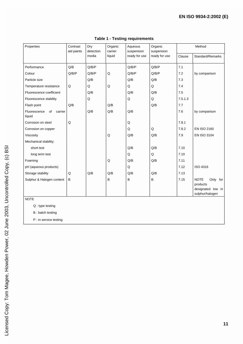
Table 1 - Testing requirements
MethodProperties Contrastaid paints
Drydetectionmedia
Organiccarrierliquid
Aqueoussuspensionready for use
Organicsuspensionready for use Clause Standard/Remarks
Performance Q/B Q/B/P Q/B/P Q/B/P 7.1
Colour Q/B/P Q/B/P Q Q/B/P Q/B/P 7.2 by comparison
Particle size Q/B Q/B Q/B 7.3
Temperature resistance Q Q Q Q Q 7.4
Fluorescence coefficient Q/B Q/B Q/B 7.5
Fluorescence stability Q Q Q 7.5.1.3
Flash point Q/B Q/B Q/B 7.7
Fluorescence of carrierliquid
Q/B Q/B Q/B 7.6 by comparison
Corrosion on steel Q Q 7.8.1
Corrosion on copper Q Q 7.8.2 EN ISO 2160
Viscosity Q Q/B Q/B 7.9 EN ISO 3104
Mechanical stability:
short test
long term test
Q/B
Q
Q/B
Q
7.10
7.10
Foaming Q Q/B Q/B 7.11
pH (aqueous products) Q 7.12 ISO 4316
Storage stability Q Q/B Q/B Q/B Q/B 7.13
Sulphur & Halogen content B B B B 7.15 NOTE Only forproductsdesignated low insulphur/halogen
NOTE
Q : type testing
B : batch testing
P : in service testing
Lice
nsed
Cop
y: T
om M
agee
, How
den
Pow
er, 0
2 Ju
ne 2
003,
Unc
ontr
olle
d C
opy,
(c)
BS
I

EN ISO 9934-2:2002 (E)
12
Dimensions in millimetres
Material: nonferromagneticsteel protectedagainstcorrosion
Gap dimensionssh = 2 ± 0,5s1, …, s4 = 2 ± 0,5 (s1 +s3) / 2 = 2 ± 0,2 (s2 + s4) /2 = 2 ± 0,2
Tolerances are to beensured in the 4 bladepositions
Key
1 Motor 9 Axle
2 Clutch 10 3 supports
3 Motor plate 11 Pilot ring
4 Support ring distance setting 10 mm from the bottom 12 Felt
5 Fixture by angle profiles 13 Basic plate
6 Spraying plate 14 Blade
7 Cup ISO 3819 - HF 2000
8 4 stator plates, 2 mm thick - Height of support ~ 170 mm
Figure 2 - Construction of the stirring arrangement to 7.10.2
Lice
nsed
Cop
y: T
om M
agee
, How
den
Pow
er, 0
2 Ju
ne 2
003,
Unc
ontr
olle
d C
opy,
(c)
BS
I

EN ISO 9934-2:2002 (E)
13
Annex A (normative)
Procedure for type, batch and in service testing
A.1 Preparation of the detection media
The detection media shall be prepared in accordance with the manufacturer's instructions.
A.2 Cleaning of the reference blocks
The reference block shall be cleaned by a suitable method to ensure that it is free from fluorescent material, oxide,dirt and grease and has a water break free surface.
A.3 Application of the detection media
Detection media shall be applied to reference blocks No. 1 and No. 2 as detailed in annex B in accordance withEN ISO 9934-1.
Spraying: 3 s to 5 s.
Specimen pitch angle: 45° ± 10°.
Spraying direction: 90° ± 10° to the surface under examination.
A.4 Inspection and interpretation
A.4.1 Inspection
Test pieces shall be inspected under viewing conditions described in EN ISO 3059.
A.4.2 Interpretation
A.4.2.1 Type and batch testing
The test shall be carried out three times and an average of the results shall be used. Indications shall be evaluatedvisually or by an equivalent measuring method.
A.4.2.1.1 Reference block type 1
The indications shall be compared to those produced by the reference detection media (e.g. by a photograph).
The result shall be reported.
A.4.2.1.2 Reference block type 2
The cumulative length of the indications shall be reported.
Lice
nsed
Cop
y: T
om M
agee
, How
den
Pow
er, 0
2 Ju
ne 2
003,
Unc
ontr
olle
d C
opy,
(c)
BS
I

EN ISO 9934-2:2002 (E)
14
A.4.2.2 In service testing
Using test block type 1 or type 2 the indications produced shall be compared with known results.
A.5 Contrast aid paint
Contrast aid paint shall be tested in accordance with A.1 to A.4.2.1, except that the contrast aid paint shall beapplied in accordance with the manufacturer's instructions after cleaning the reference test block (see A.2).
Lice
nsed
Cop
y: T
om M
agee
, How
den
Pow
er, 0
2 Ju
ne 2
003,
Unc
ontr
olle
d C
opy,
(c)
BS
I
EN ISO 9934-2:2002 (E)
15
Annex B (normative)
Reference blocks
B.1 Reference block type 1
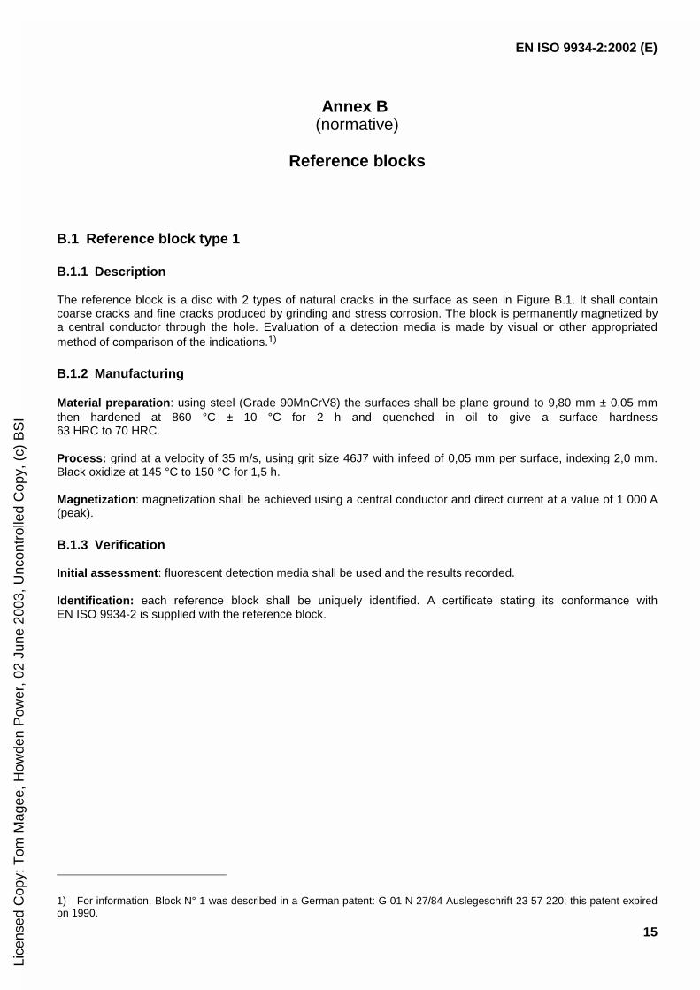
B.1.1 Description
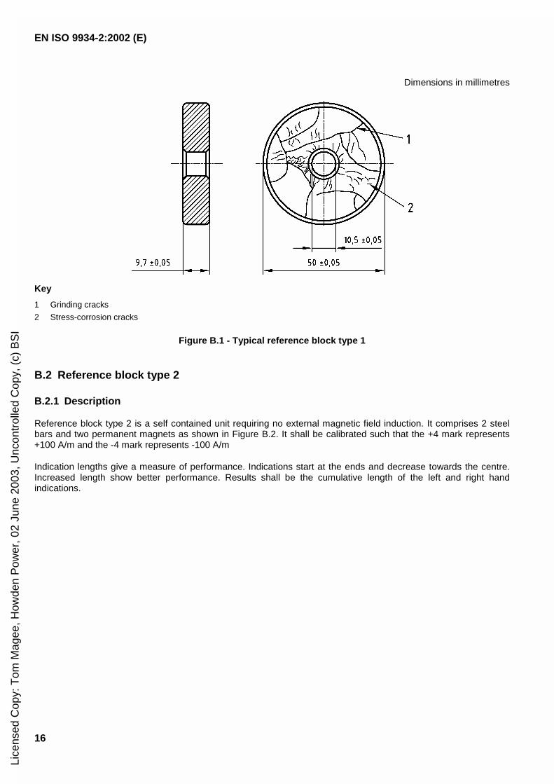
The reference block is a disc with 2 types of natural cracks in the surface as seen in Figure B.1. It shall containcoarse cracks and fine cracks produced by grinding and stress corrosion. The block is permanently magnetized bya central conductor through the hole. Evaluation of a detection media is made by visual or other appropriatedmethod of comparison of the indications.1)
B.1.2 Manufacturing
Material preparation : using steel (Grade 90MnCrV8) the surfaces shall be plane ground to 9,80 mm ± 0,05 mmthen hardened at 860 °C ± 10 °C for 2 h and quenched in oil to give a surface hardness63 HRC to 70 HRC.
Process: grind at a velocity of 35 m/s, using grit size 46J7 with infeed of 0,05 mm per surface, indexing 2,0 mm.Black oxidize at 145 °C to 150 °C for 1,5 h.
Magnetization : magnetization shall be achieved using a central conductor and direct current at a value of 1 000 A(peak).
B.1.3 Verification
Initial assessment : fluorescent detection media shall be used and the results recorded.
Identification: each reference block shall be uniquely identified. A certificate stating its conformance withEN ISO 9934-2 is supplied with the reference block.
1) For information, Block N° 1 was described in a German patent: G 01 N 27/84 Auslegeschrift 23 57 220; this patent expiredon 1990.
Lice
nsed
Cop
y: T
om M
agee
, How
den
Pow
er, 0
2 Ju
ne 2
003,
Unc
ontr
olle
d C
opy,
(c)
BS
I
EN ISO 9934-2:2002 (E)
16
Dimensions in millimetres
Key
1 Grinding cracks
2 Stress-corrosion cracks
Figure B.1 - Typical reference block type 1
B.2 Reference block type 2
B.2.1 Description
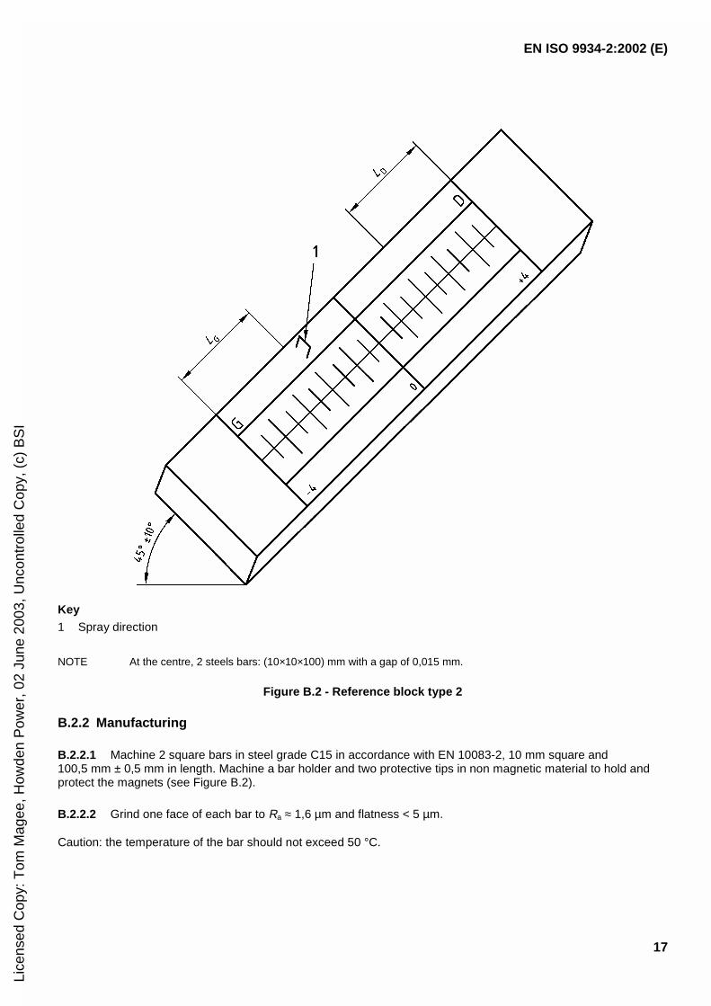
Reference block type 2 is a self contained unit requiring no external magnetic field induction. It comprises 2 steelbars and two permanent magnets as shown in Figure B.2. It shall be calibrated such that the +4 mark represents+100 A/m and the -4 mark represents -100 A/m
Indication lengths give a measure of performance. Indications start at the ends and decrease towards the centre.Increased length show better performance. Results shall be the cumulative length of the left and right handindications.
Lice
nsed
Cop
y: T
om M
agee
, How
den
Pow
er, 0
2 Ju
ne 2
003,
Unc
ontr
olle
d C
opy,
(c)
BS
I
EN ISO 9934-2:2002 (E)
17
Key1 Spray direction
NOTE At the centre, 2 steels bars: (10×10×100) mm with a gap of 0,015 mm.
Figure B.2 - Reference block type 2
B.2.2 Manufacturing
B.2.2.1 Machine 2 square bars in steel grade C15 in accordance with EN 10083-2, 10 mm square and100,5 mm ± 0,5 mm in length. Machine a bar holder and two protective tips in non magnetic material to hold andprotect the magnets (see Figure B.2).
B.2.2.2 Grind one face of each bar to Ra ≈ 1,6 µm and flatness < 5 µm.
Caution: the temperature of the bar should not exceed 50 °C.
Lice
nsed
Cop
y: T
om M
agee
, How
den
Pow
er, 0
2 Ju
ne 2
003,
Unc
ontr
olle
d C
opy,
(c)
BS
I

EN ISO 9934-2:2002 (E)
18
B.2.2.3 Demagnetize the two bars.
B.2.2.4 Insert between the ground faces of the two bars a sheet of aluminium having a thickness of 15 µm, thenplace the set in the bar holder.
B.2.2.5 Clamp the bars in position.
B.2.2.6 Fit the magnets' protective tips.
B.2.2.7 Grind the upper surface of the assembly to Ra ≈ 1,6 µm.
B.2.2.8 Remove the magnets' protective tips.
B.2.2.9 Insert the magnets (small door catch type: for example CF 12-6N2) as shown by the schema (Figure B.3).The shunts in steel with thickness of 0,2 mm are used to adjust the value of the magnetic field.
Key
1 Shunt
Figure B.3 - Schema showing the inserted magnets
B.2.2.10 Assemble the magnets' protective tips.
B.2.2.11 Engrave the upper face as shown in Figure B.4. Engraving shall not be closer than 2 mm to the gap.
2) Magnet CF 12-6N produced by ARELEC company is an example of a suitable product commercially available. Thisinformation is given for the convenience of users of this standard and does note constitute an endorsement by CEN of theproduct named.
Lice
nsed
Cop
y: T
om M
agee
, How
den
Pow
er, 0
2 Ju
ne 2
003,
Unc
ontr
olle
d C
opy,
(c)
BS
I

EN ISO 9934-2:2002 (E)
19
-4 G = - 100 A/m +4 D = + 100 A/mKey1 Gap
Figure B.4 - Engraving of reference block type 2
B.2.3 Verification
B.2.3.1 Using a tangential field strength meter, measure the field perpendicular to the artificial defect at the +4and -4 graduations.
B.2.3.2 Acceptance criteria
Value of the field at graduation -4: - 100 A/m ± 10 %.
Value of the field at graduation +4: + 100 A/m ± 10 %.
If these values are not satisfied, repeat the procedure from B.2.2.9 adjusting the field values with the shunts.
B.2.3.3 Identification
Each reference block type 2 is identified by a unique serial number.
A certificate stating its conformance with EN ISO 9934-2 is supplied with the reference block.
Lice
nsed
Cop
y: T
om M
agee
, How
den
Pow
er, 0
2 Ju
ne 2
003,
Unc
ontr
olle
d C
opy,
(c)
BS
I

EN ISO 9934-2:2002 (E)
20
Annex C (normative)
Corrosion testing of steel
C.1 Principle
The corrosive properties of detection media shall be determined by visual examination of the corrosion traces lefton a filter paper by granules previously impregnated with the liquid for examination under specified conditions.
After the corrosion test, the manufacturer of magnetic particle testing products shall report the conditions of thegranules. It is, however, recommended to use granules permitting test reproducibility.
If mutually agreed, specific granules can be supplied by the user for the manufacturer to use in corrosion testing ofthe magnetic particle testing products.
If these are not available or in case of a dispute, the granules defined in C.3 shall be used.
C.2 Apparatus
C.2.1 Petri-dish made of glass, of 100 mm outside diameter.
C.2.2 Pipette with ml scale.
C.2.3 Round filter paper, ø 90 mm, with a 40 mm diameter circle inscribed on it with indelible ink.
C.2.4 Stainless steel spatula.
C.2.5 Mesh 5 sieve in accordance with ISO 2591-1.
C.2.6 Balance accurate to 0,1 g.
C.3 Reagents and materials
C.3.1 Acetone;
C.3.2 Xylene;
C.3.3 Steel granules grade 2C40 (according to EN 10083-1), generally 2,5 × 2,5 mm;
C.3.4 Lamellar graphite general purpose cast iron granules;
(S > 0,18 %, P < 0,12 %) dry machined, approximately 2,5 mm × 2,5 mm.
The granules shall be carefully degreased with xylene in an appropriate equipment.
Lice
nsed
Cop
y: T
om M
agee
, How
den
Pow
er, 0
2 Ju
ne 2
003,
Unc
ontr
olle
d C
opy,
(c)
BS
I

EN ISO 9934-2:2002 (E)
21
C.3.5 Hard water.
C.3.6 Different stock solutions shall be prepared:
Solution A: dissolve 40 g CaCl2�6H2O in distilled water and complete to 1 l.
Solution B: dissolve 44 g MgSO4�7H2O in distilled water and complete to 1 l.
C.3.7 From these stock solutions prepare three diluted solutions as follows:
a) 2,90 ml of solution A + 0,5 ml of solution B in 1 l of distilled water;
b) 10,7 ml of solution A + 1,7 ml of solution B in 1 l of distilled water;
c) 19 ml of solution A + 3 ml of solution B in 1 l of distilled water.
C.4 Test procedure
C.4.1 Preparation of the solutions (100 ml)
Introduce successively into three 100 ml volumetric flasks the same test portion of the product under examination.Dilute each test portion to the mark using waters of different hardnesses (solutions a, b, c prepared in C.3.7).Proceed similarly for the other 2 concentrations.
C.4.2 Preparation of the granules and filters
The degreased cast iron and steel granules shall first be visually inspected for rust deposits.
Prepare a set of filters bearing ø 40 mm concentric circles inscribed with an oil pencil.
The following is required to test each magnetic particle testing product:
9 filters for testing with steel granules (solutions with three different increasing concentrations, prepared fromwaters with three different hardnesses),
9 filters for testing with cast iron granules.
Sieve the granules to remove any undersized particles and traces of dust.
Place the prepared filters in the Petri-dishes. Distribute 2 g ± 0,1 g of granules over the circumscribed area of eachfilter.
C.4.3 Corrosion testing
Wet the granules in each of the dishes using 2 ml of the relevant solution applied in one application.
Repeat the same operation for each solution with the steel and cast iron granules.
Check that there is no bubble under the filter paper, cover the Petri-dishes.
Leave the dishes at room temperature (23 ± 1) °C for 2 h ± 10 min, in a place protected from drafts and sunshine.
At the end of this time interval, remove the granules by turning the filter paper upside down by hand.
Rinse copiously with distilled water, dispensed from a water wash bottle, to remove any granules adhering to thepaper.
Lice
nsed
Cop
y: T
om M
agee
, How
den
Pow
er, 0
2 Ju
ne 2
003,
Unc
ontr
olle
d C
opy,
(c)
BS
I

EN ISO 9934-2:2002 (E)
22
Dip twice in acetone, then dry at room temperature.
C.5 Interpretation of the results
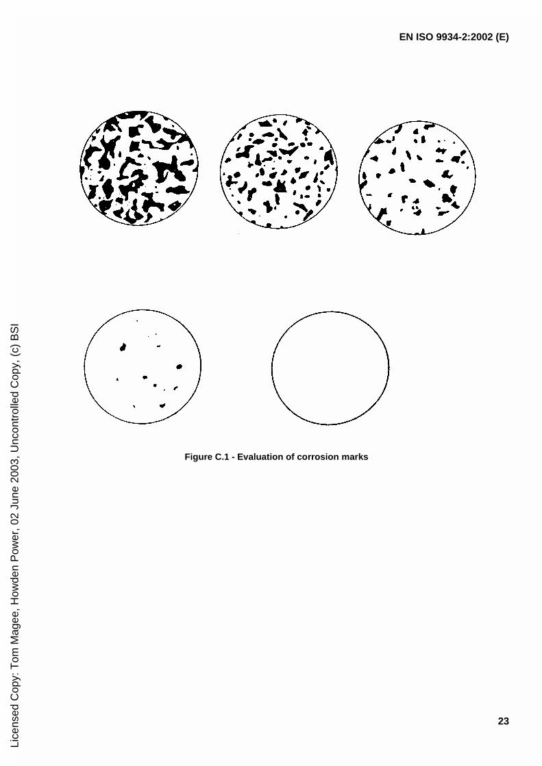
The corrosion marks left on the filter paper after washing and drying shall be immediately interpreted by visualexamination without optical instruments. Figure C.1 is intended to facilitate reading.
NOTE A quantitative evaluation of the stained surface can be made using a transparent (1 mm square) paper grid.
Table C.1 - Grading of corrosion stains on the filter paper
Grade Meaning Surface description
0 no corrosion no stain
1 corrosion traces max. 3 stains of less than 1 mm diameter
2 low corrosion less than 1 % of the surface
3 average corrosion more than 1 % and less than 5 % of the surface
4 strong corrosion more than 5 % of the surface
C.6 Expression of results
In case of uncertainties as to the grade, allocate the higher numbered grade.
The results shall be recorded together with:
identification of the tested sample;
product concentration and water hardness;
any required comment on the test;
date.
C.7 Uncertainties
The applicability of the test results shall be assessed from tests of:
repeatability:
two tests carried out by one operator under the same conditions are considered acceptable and valid whenthe 4 values of the two measuring pairs do not differ by more than one scale unit;
reproducibility and precision:
two tests carried out in two different laboratories under reproducible analogous conditions are consideredacceptable and valid when the readings for the same measurements do not differ by more than one scaleunit.
Lice
nsed
Cop
y: T
om M
agee
, How
den
Pow
er, 0
2 Ju
ne 2
003,
Unc
ontr
olle
d C
opy,
(c)
BS
I
EN ISO 9934-2:2002 (E)
23
Figure C.1 - Evaluation of corrosion marks
Lice
nsed
Cop
y: T
om M
agee
, How
den
Pow
er, 0
2 Ju
ne 2
003,
Unc
ontr
olle
d C
opy,
(c)
BS
I

EN ISO 9934-2:2002 (E)
24
Bibliography
ISO 3819, Laboratory glassware (beaker).
BS 3406-5, Methods for determination of particle size distribution. Recommendations for electrical sensingzonemethod (the Coulter principle).
NF X 11-666, Particle size analysis of powders - Diffraction method.
Lice
nsed
Cop
y: T
om M
agee
, How
den
Pow
er, 0
2 Ju
ne 2
003,
Unc
ontr
olle
d C
opy,
(c)
BS
I

Lice
nsed
Cop
y: T
om M
agee
, How
den
Pow
er, 0
2 Ju
ne 2
003,
Unc
ontr
olle
d C
opy,
(c)
BS
I
BS EN ISO 9934-2:2002
BSI
389 Chiswick High Road
London
W4 4AL
BSI — British Standards InstitutionBSI is the independent national body responsible for preparing British Standards. It presents the UK view on standards in Europe and at the international level. It is incorporated by Royal Charter.
Revisions
British Standards are updated by amendment or revision. Users of British Standards should make sure that they possess the latest amendments or editions.
It is the constant aim of BSI to improve the quality of our products and services. We would be grateful if anyone finding an inaccuracy or ambiguity while using this British Standard would inform the Secretary of the technical committee responsible, the identity of which can be found on the inside front cover. Tel: +44 (0)20 8996 9000. Fax: +44 (0)20 8996 7400.
BSI offers members an individual updating service called PLUS which ensures that subscribers automatically receive the latest editions of standards.
Buying standards
Orders for all BSI, international and foreign standards publications should be addressed to Customer Services. Tel: +44 (0)20 8996 9001. Fax: +44 (0)20 8996 7001. Email: [email protected]. Standards are also available from the BSI website at http://www.bsi-global.com.
In response to orders for international standards, it is BSI policy to supply the BSI implementation of those that have been published as British Standards, unless otherwise requested.
Information on standards
BSI provides a wide range of information on national, European and international standards through its Library and its Technical Help to Exporters Service. Various BSI electronic information services are also available which give details on all its products and services. Contact the Information Centre. Tel: +44 (0)20 8996 7111. Fax: +44 (0)20 8996 7048. Email: [email protected].
Subscribing members of BSI are kept up to date with standards developments and receive substantial discounts on the purchase price of standards. For details of these and other benefits contact Membership Administration. Tel: +44 (0)20 8996 7002. Fax: +44 (0)20 8996 7001. Email: [email protected].
Information regarding online access to British Standards via British Standards Online can be found at http://www.bsi-global.com/bsonline.
Further information about BSI is available on the BSI website at http://www.bsi-global.com.
Copyright
Copyright subsists in all BSI publications. BSI also holds the copyright, in the UK, of the publications of the international standardization bodies. Except as permitted under the Copyright, Designs and Patents Act 1988 no extract may be reproduced, stored in a retrieval system or transmitted in any form or by any means – electronic, photocopying, recording or otherwise – without prior written permission from BSI.
This does not preclude the free use, in the course of implementing the standard, of necessary details such as symbols, and size, type or grade designations. If these details are to be used for any other purpose than implementation then the prior written permission of BSI must be obtained.
Details and advice can be obtained from the Copyright & Licensing Manager. Tel: +44 (0)20 8996 7070. Fax: +44 (0)20 8996 7553. Email: [email protected].
Lice
nsed
Cop
y: T
om M
agee
, How
den
Pow
er, 0
2 Ju
ne 2
003,
Unc
ontr
olle
d C
opy,
(c)
BS
I