librepilot gcs tutorial - drone team · either actual hardware running through the telemetry link...
TRANSCRIPT
Making and designing a toy drone through multidisciplinary collaborative work
Project no.2015‐1‐ES01‐KA202‐015925
page 1 of 13
LibrePilot GCS
Tutorial
BY
Wirginia Tomczyk

Making and designing a toy drone through multidisciplinary collaborative work
Project no.2015‐1‐ES01‐KA202‐015925
page 2 of 13
Introduction
The first dron of Drone Team project use Open Pilot Copter Control (CC). It is
the flight controller supported by LibrePilot firmware. The LibrePilot is Ground
Control Station (GCS)
GCS allow you to observe the parameters of flight, check and configure
components of drone like accelerometr, gyroscope, gps.
The official web site of this project is: www.librepilot.org. The second very
usefull site is http://opwiki.readthedocs.io/en/latest/user_manual/index.html
This documentation is besed on these sources.

Making and designing a toy drone through multidisciplinary collaborative work
Project no.2015‐1‐ES01‐KA202‐015925
page 3 of 13
Getting to know your board

Making and designing a toy drone through multidisciplinary collaborative work
Project no.2015‐1‐ES01‐KA202‐015925
page 4 of 13
Sensors and Components
3-axis Gyroscope array: IDG-500 and ISZ-500
3-axis Accelerometer: ADXL345
The main function of gyroscope technology is to improve the drones flight capabilities. With six axis drone stabilization working with other components, every aspect improves such as flying or hovering perfectly stable and steeper angled turns. The gyroscope needs to work almost instantly to the forces moving against the drone. The gyroscope provides essential navigational information to the central flight control systems.
An accelerometer is a device that measures proper acceleration. It helps to
come back to right position.
Having these two sensors allow to fly in two ways:
Manual - Similar to flying a helicopter. Once you tilt the quadcopter (roll)
it will not auto-level itself back to its original position. Even if you let go
of the stick and it returns to the middle, the quadcopter will stay tilted.
Attitude (Auto-level) – Once the sticks are centered, the copter will level itself out.
Libre Pilot GCS The LibrePilot is organized into tabs and pages for easy navigation. You can find them on the bottom of window. There are:
Welcome Tab:
The greeting tab which shows you the latest project information and activity, provides buttons for the other pages, as well as containing the start button for the Vehicle Setup Wizard.
Flight Data Tab
Displays live data from the flight controller.

Making and designing a toy drone through multidisciplinary collaborative work
Project no.2015‐1‐ES01‐KA202‐015925
page 5 of 13
Configuration Tab
This tab contains sub pages which enable you to configure major elements of the flight controller using simple graphical interfaces. None of the sub pages are active unless a flight controller is connected to GCS.
System
A configurable interface for viewing and modifying advanced settings, live data, GPS data and more.
Scopes
Real-time graphing of flight controller data. Care should be taken to not let auto-scaling fool you into thinking you have a problem where there is none. The longer a scope is functioning, the tighter the scale may get, and a very small deviation in a value may look significant when it's not.
HITL
An interface for the GCS to act as a bridge between a flight simulator, and either actual hardware running through the telemetry link or simulated hardware running on the computer.
Firmware: Inspect the current firmware version, and upgrade the bootloader/firmware of the flight controller.

Making and designing a toy drone through multidisciplinary collaborative work
Project no.2015‐1‐ES01‐KA202‐015925
page 6 of 13
The screen show you the Flight Data panel. Now the drone is not connected.
Since you combine drone, the panel show you the movement of drone and the
status of components.

Making and designing a toy drone through multidisciplinary collaborative work
Project no.2015‐1‐ES01‐KA202‐015925
page 7 of 13
Flight Data Tab consist of:
1. Map 2. Model View 3. PFD - The Primary Flight Data display all information from current
board connected to GCS. 4. SystemHealth –
Atti
Shows the status of the board’s attitude data. If all is well with gyroscope and
accelerometer, it turns green after gyroscope calibration upon power up, or if
you are using “GPS Navigation (INS13GPSOutdoor)” stabilization mode, when
the Inertial Navigation System’s Extended Kalman Filter (EKF) has fired up.
EKF is a sophisticated sensor fusion algorithm that takes data from relevant
sensors and creates a best possible estimation of the board’s angle, velocity
and position.
Attitude data not available, waiting for gyroscope calibration.
Don’t move the vehicle while gyros are being calibrated upon board power-
up. There is no data coming in from the sensors, which usually indicates
faulty onboard sensors on CC3D and unknown home location on Revo. For
Revo this is normal when you have not had GPS fix yet on a new build.
The home location will be automatically set when GPS gets enough
satellites and good fix. The sensors can be damaged in a bad crash.
Otherwise, contact board seller.
Data is received from the sensors, but attitude information is not
available. This usually happens when the EKF is not running yet. Make
sure that GPS and MAG alarms are green, and that all calibrations have
been done properly. It sometimes helps to move the vehicle around a bit to
give EKF a better view of what’s going on with sensors.
EKF is running, but the state estimation is not optimal. Good
calibration and moving the vehicle a bit helps this situation.
The system has a clear view of the state of the vehicle.

Making and designing a toy drone through multidisciplinary collaborative work
Project no.2015‐1‐ES01‐KA202‐015925
page 8 of 13
Stab
Shows whether the board is capable of stabilizing flight. This status goes very
much hand in hand with Atti.
Waiting for gyroscope calibration. Don’t move the vehicle while
gyros are being calibrated upon board power-up.
The stabilization module cannot stabilize flight.
Can be a brief alarm when one gyroscope update is missng.
Stabilization of flight can be performed.
Sensor
GPS
Shows the status of the GPS that can be connected to an OpenPilot flight
controller. GPS is required for autonomous missions and more sophisticated
flight modes.
A GPS has not been configured to be used.
The GPS has been configured, but no valid data is coming in.
This is normal if flight battery is not connected, because GPS only gets
power from external sources, not USB. Check the baud rate and the used
protocol of your GPS. Double check serial connection, TX/RX need to be
crossed between board and GPS.
Serial communication is fine but the GPS has no valid fix. Wait
for GPS to gather satellites, and preferably have your vehicle in an open
area.
The GPS has a fix and navigation can be used. However, the
position quality is very low (the indication <7 satellites and/or PDOP >
3.5m). A blue LED will flash on the OP v8 and v9 GPS.
The GPS has a valid 3D fix.

Making and designing a toy drone through multidisciplinary collaborative work
Project no.2015‐1‐ES01‐KA202‐015925
page 9 of 13
Input
Input module handles the data that is coming from your receiver.
R/C input has not been configured. Use Input tab or Transmitter
Setup Wizard to configure your radio channel inputs.
No R/C input data. Power up receiver with the flight battery.
Valid R/C input data is coming in.
Output
Output module takes motor speed and servo position data from stabilization
algorithms, and feeds it into output channels.
Channel outputs have not been configured. Use Vehicle Setup
Wizard to configure them automatically.
Outputs are configured and can be updated.
I2C
I2C is a bus that connects onboard or auxiliary sensors and handles the data
transmissions. I2C is designed for communications internal to a PCB, and
does not work well via wire connections. It is okay to use for LED controls and
similar functions, but is absolutely not recommended for flight-critical sensor
connections.
I2C module is not being used.
I2C module is in error state.
I2C communications are up and working properly.

Making and designing a toy drone through multidisciplinary collaborative work
Project no.2015‐1‐ES01‐KA202‐015925
page 10 of 13
Link
Telemetry
Shows the status of Telemetry communications module
Telemetry module has encountered an error. Set up only
one telemetry output port.
Telemetry data communications are working properly.
Pwr (Power)
Batt
Battery status shows whether you have enough voltage in the battery to fly.
Set limits for this in FlightBatt (CHECK this) settings. It requires a battery
voltage sensor to work. Battery monitoring module can be enabled in system
settings’ optional modules.
Battery monitoring module is not enabled.
Not enough battery voltage to safely take off. Default limit is
3.1V/Cell.
Battery voltage is low, but flying is possible. Default limit is
3.4V/Cell.
Battery voltage is ok.
Time
Shows whether you have enough energy in the battery left for flying, and
requires a battery voltage and current sensor to work. Currently has a bug
when not using a current sensor; set the battery capacity to 0. This disables
the estimated flight time counter and associated alarms.
Battery monitoring module is not enabled, see above Batt explanation.

Making and designing a toy drone through multidisciplinary collaborative work
Project no.2015‐1‐ES01‐KA202‐015925
page 11 of 13
Battery energy is low, flying cannot be performed safely.
Low amount of energy in the battery, flying is still possible.
Good amount of energy left in the battery to fly.
Misc
Config
Shows whether your flight controller board has been properly set up.
Board configuration problem. If you have set up GPS modes
(GPS Assist, PosHold, RTB) to one flight mode, then make sure that “GPS
Navigation (INS13)” fusion algorithm is selected.
CC3D can’t use GPS Navigation (INS13) and do not support GPS Assisted
modes.
Select GPS Navigation (INS13) in Config > Attitude
tab > Parameters > Attitude Estimation Algorithm.
Board configuration ok.
Sys (System)
Boot
Shows that a board reboot is required, or fail-safe settings have been loaded
upon boot.
Boot alarm can be caused by various reasons:
o No valid telemetry option selected, so board will boot with default USB
telemetry
o Board init failed due to driver, module or RAM issues, and the board has been
booted up in fail-safe state
o Board has been put to safe mode by the user
o Board needs a reboot after hardware configuration changes
Flight controller booted up properly.
Making and designing a toy drone through multidisciplinary collaborative work
Project no.2015‐1‐ES01‐KA202‐015925
page 12 of 13
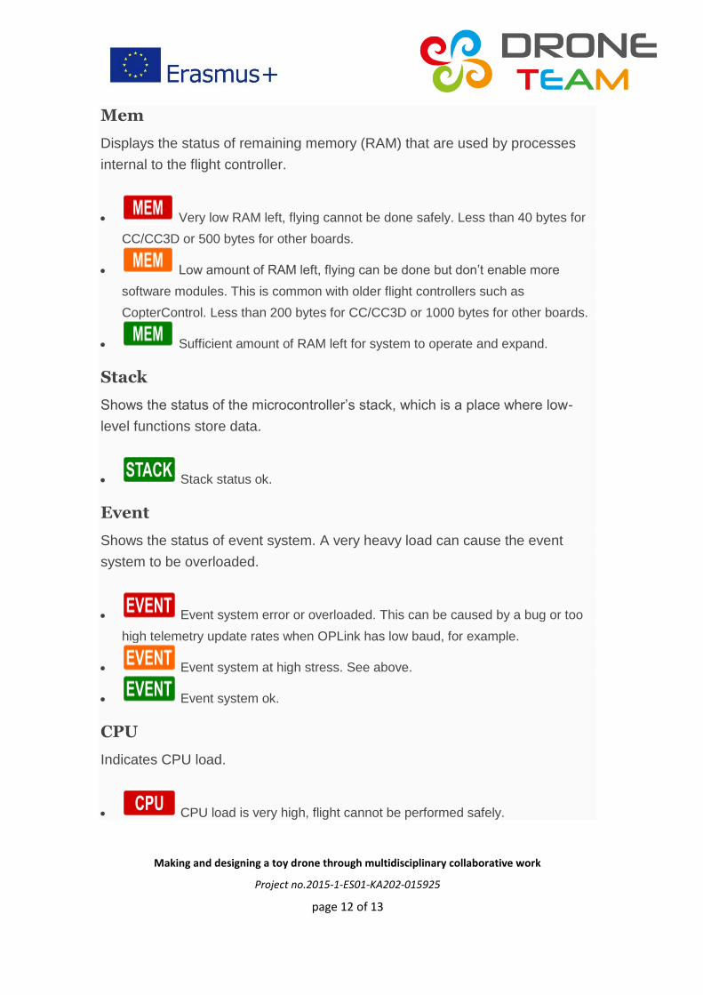
Mem
Displays the status of remaining memory (RAM) that are used by processes
internal to the flight controller.
Very low RAM left, flying cannot be done safely. Less than 40 bytes for
CC/CC3D or 500 bytes for other boards.
Low amount of RAM left, flying can be done but don’t enable more
software modules. This is common with older flight controllers such as
CopterControl. Less than 200 bytes for CC/CC3D or 1000 bytes for other boards.
Sufficient amount of RAM left for system to operate and expand.
Stack
Shows the status of the microcontroller’s stack, which is a place where low-
level functions store data.
Stack status ok.
Event
Shows the status of event system. A very heavy load can cause the event
system to be overloaded.
Event system error or overloaded. This can be caused by a bug or too
high telemetry update rates when OPLink has low baud, for example.
Event system at high stress. See above.
Event system ok.
CPU
Indicates CPU load.
CPU load is very high, flight cannot be performed safely.

Making and designing a toy drone through multidisciplinary collaborative work
Project no.2015‐1‐ES01‐KA202‐015925
page 13 of 13
CPU load is high, but flight can be performed. Don’t enable more
software modules like TPS or board rotation. Should only occurs for CC/CC3D.
CPU load is at an acceptable level, and flying is safe.
Configuration tab
Important tip:
Before you start changing configuration you can save the current state in
menu File -> Export UAV Settings. It is good for beginners – it could happened
that after some changes your dron stop flying. In thiat situation you can Import
UAV Setting and fly again.
Here you can configure your board.