libration orbit mission design: of numerical and dynamical methods
TRANSCRIPT

j . . . Libration Point Orbits and Applications June 10-14,2002, Girona, Spain
Libration Orbit Mission Design: Applications Of Numerical And Dynamical Methods
David Folta Flight Dynamics Analysis Branch (Code 572)
NASA Goddard Space Flight Center, Greenbelt MD, USA, 2077 1 [email protected]
Mark Beckman Flight Dynamics Analysis Branch (Code 572)
NASA Goddard Space Flight Center, Greenbelt MD, USA, 2077 1 mark. [email protected]
Abstract: Sun-Earth libration point orbits serve as excellent locations for scientific investigations. These orbits are often selected to minimize environmental disturbances and maximize observing efficiency. Trajectory design in support of libration orbits is ever more challenging as more complex missions are envisioned in the next decade. Trajectory design software must be further enabled to incorporate better understanding of the libration orbit solution space and thus improve the efficiency and expand the capabilities of current approaches.
The Goddard Space Flight Center (GSFC) is currently supporting multiple libration missions. This end-to-end support consists of mission operations, trajectory design, and control. It also includes algorithm and software development. The recently launched Microwave Anisotropy Probe (MAP) and upcoming James Webb Space Telescope (JWST) and Constellation-X missions are examples of the use of improved numerical methods for attaining constrained orbital parameters and controlling their dynamical evolution at the collinear libration points. This paper presents a history of libration point missions, a brief description of the numerical and dynamical design techniques including software used, and a sample of future GSFC mission designs.
INTRODUCTION Sun-Earth libration point orbits serve as excellent locations for scientific investigations of stellar
and galactic physics. These orbits are often selected to minimize environmental impacts and disturbances and to maximize observing efficiency. Trajectory design in support of such missions is challenging as more complex mission designs are envisioned. To meet these challenges, trajectory design software must be further enhanced to incorporate better understanding of the libration orbit solution space and to encompass new optimal methods. Thus the support community needs to improve the efficiency and expand the capabilities of current approaches. For example, invariant manifolds, derived from dynamical systems theory, have been applied to trajectory design over the past few years. The manifold approach offers new insights into the natural dynamics associated with the multi-body Overall it allows a more rapid and robust methodology to libration orbit and transfer orbit design when used in combination with numerical techniques. Trajectory design approaches should also include improved numerical targeting methods that allow optimization and a dynamical view of the state space allowing the user rapid intuitive feedback.
An Overview Of NASA Themes Involving Libration Orbits The NASA Enterprises of the Space Sciences (SSE) and Earth Sciences (ESE) are a combination
of several programs and themes that will benefit from the applications of improved numerical and dynamical approaches to meet mission trajectory designs3. The Space Sciences Enterprise includes themes such as Sun-Earth-Connections (SEC), Origins, the Structure and Evolution of the Universe (SEU), and Exploration of the Solar System (ESS). Each of these themes call for missions in libration point orbits. The attainment and maintenance of the particular orbits will bk a challenge for the mission designer. For example, the desire to obtain a specific libration orbit and eliminate shadows and minimize fuel requirements while meeting specific payload needs will be a significant technology payoff.
SEC missions will use orbits that provide unique coverage for solar observation and Earth’s environmental regions. Recent SEC missions included the L1 libration point mission SOH0 and the L1/L2 WIND mission; both missions used conceptual manifold implementations. The Living With a Star (LWS)
1
https://ntrs.nasa.gov/search.jsp?R=20030025265 2019-03-30T11:34:17+00:00Z

Libration Point Orbits and Applications June IO-14,2002, Girona, Spain
theme of the SEC may require mission design of trajectories that place spacecraft into heliocentric orbits and libration orbits at the L1 and L3 Sun-Earth libration points.
Other Space Science challenges include the Structure and Evolution of the Universe (SEU) program. Currently the Micro Arcsecond X-ray Imaging Mission (MAXIM) and Constellation-X missions of the SEU are libration point orbiters, with each mission a formation-flying concept.
As found on the Origins web site, “The Origins Program has embarked on a series of closely lmked missions that build on prior achievements. As each Origins mission makes radical advances in technology, innovations will be fed forward from one generation of missions to the next. By the end of the decade, we will have combined the very best imaging, formation flying, and other visionary technologies, giving us the power of enormous telescopes at a fraction of the cost.” A major goal of the Space Sciences’ Origins Program is the launch of the James Webb Space Telescope (JWST) and The Terrestrial Planet Finder (TPF). Each mission is to the L2 libration point. The mission design of JWST is currently employing the use of invariant manifolds to seed numerical targeting schemes.
The Triana mission of the Earth Science Enterprise (ESE) is the lone ESE mission not orbiting the Earth. It is a mission that has relied solely on manifolds for computation of its mission baseline to L1. While this mission is a significant deviation from traditional low Earth orbiters, it represents the possibilities of other Earth observing mission at unique vantage points .
A major challenge to many of the above missions is the use of interferometry to form a virtual telescope. By placing telescope components on individual formation flying spacecraft, they would form a constellation or formation that would provide a powerful single telescope. Spacecraft carrying such instruments would have to fly in a precise formation, one that would provide us with the greatest possible information. Not only will spacecraft be separated across small to very large distances, they‘ll constantly be turning and pointing at different stars, expanding and contracting the distance between them. We‘ll need improved numerical and dynamical system applications and optimal control methods to monitor and maintain less than centimeter-sized changes in position in order to make the individual systems act as one large spacecraft.
Historical Missions Even though libration orbits have become more mainstream and several missions to the Sun-Earth
collinear libration points are now proposed, current NASA libration missions have been few in number totaling only seven with five true orbiters, International Sun-Earth Explorer (ISEE3), Solar Heliospheric Observatory (SOHO), Advanced Composition Explorer (ACE), Microwave Anisotropy Probe (MAP), and Genesis and two that stayed briefly in a libration orbit, WIND and Geotail. The Flight Dynamics Analysis Branch (FDAB) of the Goddard Space Flight Center (GSFC) has designed and supported all but one of these missions.
While libration orbits share many dynamic properties, their diversity is revealed by how mission constraints are met. In a Sun-Earth rotating coordinate fiame centered at the libration point, their geometric orientations and amplitudes may vary significantly. Also, the mathematical approach for representation of the reference orbit may differ. For ISEE-3 the complexity of mission design was handled through a combination of analytical and numerical methods to predetermine the reference libration orbit, along with proven operational numerical techniques for targeting and optimization?*5 The International Solar Terrestrial Program (ISTP) SOHO mission was the next true libration orbiter, with orbit amplitudes equal to that of the ISEE-3 While the SOHO transfer and mission orbit is similar to ISEE-3, the stationkeeping control method does not follow the ISEE-3 method of re-targeting back to a predetermined reference path. SOHO stationkeeping is performed to ensure that the orbit completes another revolution which has an added benefit of minimizing the AV required. The WIND spacecraft of the ISTP Program was originally planned as a libration orbiter, its trajectory was designed using multiple lunar gravity assist for rotation of the line of apsides to coincide with the Sun-Earth line before insertion into the L1 lissajouss. ACE was designed differently in that a direct transfer orbit was adjusted to allow a capture into a small L1 Lissajous orbit.’ The most recent GSFC mission was MAP. MAP included a lunar gravity assist to obtain a small amplitude lissajous orbit.” The Genesis mission is similar to SOHO but utilizes invariant manifolds.
Future Mission Challanges At GSFC, there is currently one mission awaiting launch, Triana, and two L2 missions in design or
formulation, the James Webb Space Telescope (JWST)” and Constellation-X. Future missions of formations such as Maxim and Stellar Imager are in their conceptual stage. These and other new missions
2

Libration Point Orbits and Applications June 10-14,2002, Girona, Spain
such as the Terrestrial Planet Finder or European Space Agency’s Darwin drive designs of constrained transfer trajectories and mission orbits 12,13. These missions are designed to meet orbit goals for specific Lissajous orbits, to minimize fuel or operational requirements, and to provide formation or constellation options. Traditionally, libration orbit design has been analyzed with a baseline trajectory concept set in place by project requirements or analytical boundary methods; that is, a trajectory had been baselined so that science requirements are met. Future mission design requires a more generalized approach as operational considerations require the launch window, gravity assist, transfer trajectories, final orbit geometry and orientation, and the number of spacecraft to be as flexible as possible to optimize science return while minimizing operational and launch requirements.
Upcoming missions also bring new challenges that individually may easily be met, but in combination they become problematic. These may include
Biased Orbits when using large sun shades Minimal Fuel Constrained communications Shadow restrictions Very small amplitudes Limited AV directions Use of external libration orbits to L4, Ls L3 Co-linear orbits
Reorientation to different planes and classes Earth-Moon libration orbits Low thrust transfers Solar sail applications Continuous control to reference trajectories Human exploration Quasi-stationary orbits Servicing of resources in libration orbits
A Brief Historv of Trajectory Design and CaDabilities GSFC libration point mission design capabilities have significantly improved over the last decade.
The success of GSFC support is based on an accurate numerical computational regime. Before 1990, mainframe computers were the only resource to compute high fidelity trajectories for libration orbits. The software of choice at that time was the Goddard Mission Analysis System (GMAS). This software had complete optimization functionality as well as the capability to model all the required perturbing forces. The software was unique at the time since it allowed object modules to be linked into the run sequence as a way to allow the user access to data for trajectory analysis. During the early 199O’s, the GSFC operational PC program called Swingby was deve10ped.I~ Swingby was developed as a replacement for GMAS with an interactive graphical user interface to provide instantaneous feedback of the trajectory design in multiple coordinate systems. It was designed to be a generic tool to support a variety of missions including, lunar, planetary, libration, and deep space and of course gravity assisted trajectory designs. Swingby provides complete mission analysis and operations for the WIND, SOHO, ACE, and is currently being used for Triana analysis and as an independent check for MAP. Additionally, the lunar orbiter missions of Lunar Prospector and Clementine also used Swingby for mission design and maneuver planning. With the unprecedented success of Swingby, GSFC invested in a commercial program called Astrogator, produced by Analytical Graphics Inc. that is based on Swingby design and mathematical specification^'^. Table- 1 presents both historic and future planned and conceptual missions.
Numerical and Dynamical Taweting Methods
It is important that libration trajectories be modeled accurately. The software must integrate spacecraft trajectories very precisely and model both impulsive and finite maneuvers. Swingby and Astrogator allow this by incorporating various high order variable or fixed step numerical integrators (Runge Kutta, Cowell, and Bulirsch-Stoer). Precise force modeling includes up to 100x100 Earth and lunar gravity potentials, solar radiation pressure, multiple 3rd-body perturbation effects and an atmospheric drag model. Varying user-selected parameters to achieve the required goals performs trajectory targeting and optimization. A differential corrector (DC) is routinely used as the method of choice for targeting. Both programs use B-plane and libration coordinate targets. These software tools are also excellent for prelaunch analysis including error analysis, launch window calculations, finite engine modeling, and ephemeris generation.
Numerical Shooting Methods Any trajectory design for libration orbit transfers and stationkeeping can be computed using
GSFC’s Swingby or Anaytical Graphic’s (AGI) Astrogator software. Currently, both of these programs use
3

Libration Point Orbits and Applications June 10-14,2002, Girona, Spain
a direct shooting approach (forward or backward) for targeting and meeting mission goals. A shooting method using a differential corrector (DC) is widely used to achieve orbit goals in these programs although both provide the user with a limited Quasi-Newton I Steepest Descent method. All three methods use numerical partial derivatives to calculate the direction for convergence. The DC in Swingby uses the first derivative information. The partial derivatives are calculated by numerically propagating to the stopping condition, changing the independent variable with a small perturbation and re-propagating. The change in the goals divided by the change in the variables are used to compute the partials. The usual sequence of a forward shooting method is to vary the initial conditions though predefined perturbations. The initial conditions include the orbital initial conditions, an applied AV, or spacecraft design parameter to meet goals that include orbital parameters such as period, position, velocity, amplitude, etc.
Table 1 - Libration Orbit Missions
ISEE-3 LlHalo/L2/Comet 175000, 660670, 120000 1978 430 Direct 1' mission
L1- Lissajous loooo, 350000,250000 1994 685 Multiple Lunar Gravity
Assist SOH0 L1 -Lissajous 206448, 666672, 12oooO 1995 275 Direct
L1- Lissajous 81775, 264071, 157406 1997 590 Direct 1" small amplitude (Constrained)
L2-Lissajous ala, 264000, 264000 2001 127 Single Lunar Gravity Assist 1' L2 Mission
WIND+
.._I- --
~ _ i - - -
r ACE
MAP Genesis j-Cl-Lissajous 25000,800000, 250000 2001 540 Direct
Triana L1-Lissajous 81000, 264000, 148000 # 620 Direct Launch
Constrained
Lissajous
Tethered Formation
Formation
Loose Formation
j Large Lissajous
-- LZ-Quasi-Periodic 290000, 800000, 131000 # 150 Direct
L2-Lissajous 290000, 800000, 131000 # Tbd Direct
JWST*
SPECS
MAXIM L1- Lissajous Large Lissajous # # Direct
Constellation-X L2 - Lissajous Large Lissjaous 2010 150-250 Single Lunar Gravity Assist -___
Darwin PL1-Lissajous 300000, 800000, 350000 2014 # #
Stellar Imager L2 - Lissajous Large Lissajous 2015 # Direct -30 S/C Formation
TPF ' ~2 - Lissajous Lissajous # # # 1 Formation? * =This information represents concept only, Lissajous orbit as part of baseline trajectory. mission concepts)
# =unknown at this time, + =WIND originally had a L, (Red represents current missions; blue represents future
The general procedures used in developing a baseline L2 direct transfer trajectory are:
0
a
0
0
Target a trajectory that yields an escape trajectory towards a libration point with the Moon at the appropriate geometry Target the anti-Sun right ascension and declinations at the appropriate launch epoch Target the solar rotating coordinate system velocity of the Sun- Earth rotating coordinate x-z plane crossing condition to achieve a quasi-libration orbit, L2 x-axis velocity - 0 Target a second x-z plane crossing velocity which yields a subsequent x-z plane crossing, then target to a one period revolution at L2
2
Libration Point Orbits and Applications June 10-14,2002, Girona, Spain
In all above conditions, vary the launch injection C3 and parking orbital parameters ( w, Q, parking orbit coast and inclination) Incorporate conditions to achieve the correct orientation of the Lissajous pattern
While the basic Swingby DC targeting procedures used in developing a baseline lunar gravity assist trajectory for L2 were:
0
0
0
Target the Moon at the appropriate encounter epoch to achieve an anti-Sun outgoing asymptote vector Target the lunar B-Plane condition to achieve gravity assist parameters and a perpendicular Sun- Earth rotating coordinate x-z plane crossing Target x-z plane crossing velocities which yields a second x-z plane crossing and target to a one period revolution at L2 Re-target lunar B-plane conditions to achieve the correct orientation of the Lissajous pattern with respect to the ecliptic plane
In both procedures, target goals may include Time (epoch, durations, flight time), B-Plane conditions (B.T B.R angle, B magnitude, outgoing asymptote vector and energy), Libration sun-Earth line crossing conditions (position, velocity, angle, energy, or a mathematical computation (eigenvectors), or other parameters at intermediate locations. Targets may be single event string, nested, or branched to allow repeatable targeting. Maneuvers can be inserted were appropriate.
These procedures are duplicated for significant changes in launch date and to include phasing loop strategies. The phasing loop strategy allows time between launch and a lunar encounter, thus providing a longer launch window since the phasing loop periods can be adjusted by maneuvers to arrive at the chosen epoch and lunar phase angle with respect to the Sun-Earth line. Targeting to an opening Lissajous pattern assures that the spacecraft will not pass through the shadow for at least 3 years (assuming control of the unstable mode). Retarget conditions via addition of deterministic AVs can be used to achieve the correct orientation and Lissajous pattern size with respect to the ecliptic plane. This procedure is duplicated for significant changes in launch date or to include lunar phasing loop strategies. Targeting to an opening Lissajous pattern assures that the spacecraft will not pass through the shadow for multiple revolutions assuming control of the unstable mode.
I t d
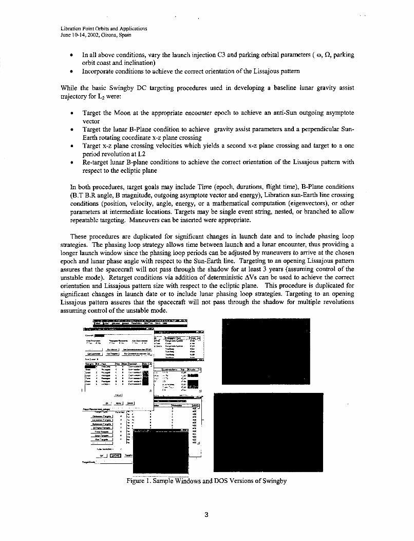
Figure 1. Sample Windows and DOS Versions of Swingby
3

Libration Point Orbits and Applications June 10-14,2002, Girona, Spain
While this procedure will achieve the required orbit, it is not robust for rapidly changing requirements. In order to decrease the difficulty in meeting mission orbit parameters and constraints in a direct targeting approach, the application of a dynamical system approach is investigated and incorporated into the overall trajectory design technique.
This procedure can also be used for backward targeting, that of using a predefined libration orbit and targeting backward in time to the launch 1 parking orbit conditions. This procedure also involves the use of a DC to provide maneuvers to attain the mission orbit and parking orbit constraints.
Using parametric scans, DC, and multiple targets, a more robust design can be achieved. Considerations are being given to new strategies that incorporate optimization routines into this scheme to ensure minimal fuel or time requirements can be met. Figure 1 presents sample output of the Windows and DOS versions of Swingby used to support GSFC missions.
Dvnamical Svstems Amroach As mission concepts become more ambitious, increasing innovation is necessary in the design of
the trajectory. Design capabilities for libration point missions have significantly improved in recent years. The success of Swingby for construction of trajectories in this regime is evidence of the improvement in computational capabilities. Nevertheless, conventional tools do not currently incorporate any theoretical understanding of the multi-body problem and do not fully exploit dynamical relationships. An in depth discussion of the versatility of dynamical systems as they apply to libration trajectory design were previously presented and is summarized below with permission.’
Invariant Manifolds Nonlinear dynamical systems theory (DST) offers insights in multi-body regimes, where
qualitative information is necessary concerning sets of solutions and their evolution.’ DST is, of course, a broad subject area with applications to many fields. For application to spacecraft trajectory design, it is helpful to first consider special solutions and invariant manifolds, since this aspect of DST offers immediate insights. Under a GSFC grant, Purdue University investigated various dynamical systems methodologies that now are included in software called Generator. In Generator, different types of solution arcs, some based on dynamical systems theory, are input to a process that differentially corrects the trajectory segments to produce a complete path in a complex dynamical model. A two level iteration scheme is utilized whenever differential corrections are required. This approach produces position continuity and then a velocity continuity for a given trajectory. An understanding of the solution space then forms a basis for computation of a preliminary libration and transfer orbit solution and the end-to-end approximation can then be transferred to a direct targeting methods like Swingby for final adjustments for launch window, launch vehicle error analysis, maneuver planning, or higher order modeling. Our current goal is to blend dynamical systems theory, which employs the dynamical relationships to construct the solution arcs into Swingby or Astrogator with strength in numerical analysis.
The geometrical theory of dynamical systems is based in phase space and begins with special solutions that include equilibrium points, periodic orbits, and quasi-periodic motions. Differential manifolds are introduced as the geometrical model for the phase space of dependent variables. An invariant manifold is defined as an n-dimensional surface such that an orbit starting on the surface remains on the surface throughout its dynamical evolution. So, an invariant manifold is a set of orbits that form a surface. Invariant manifolds, in particular stable, unstable, and center manifolds, are key components in the analysis of the phase space. Bounded motions which include periodic orbits such as halo orbits exist in the center manifold, as well as transitions from one type of bounded motion to another. Sets of orbits that approach or depart an invariant manifold asymptotically are also invariant manifolds (under certain conditions) and these are the stable and unstable manifolds, respectively, associated with the linear stable and unstable modes.
The periodic halo orbits, as defined in the circular restricted problem, are used as a reference solution for investigating the phase space in this analysis. It is possible to exploit the hyperbolic nature of these orbits by using the associated stable and unstable manifolds to generate transfer trajectories as well as general trajectory arcs in this L2 region of space.
Lissaious-Manifold-Transfer Generation The computation process of the stable and unstable manifolds, shown in Table 2, is associated
with particular halo orbit design parameters and is accomplished numerically in a straightforward manner.
4

Libration Point Orbits and Applications June 10-14,2002, Girona, Spain
Utility Input Phase (Generic Orbit) User Data
Lissajous Universe And User Data Monodromy (Periodic Orbit) Universe And Lissajous Output
. -
output Control Angles For Lissajous
Patch Point And Lissajous Orbit Fixed Points And Stable And
The procedure is based on the availability of the monodromy matrix (the variational or state transition matrix after one period of motion) associated with the lissajous orbit. A similar state transition matrix of this sort can be computed using the state equations of motion based on circular three-body restricted motion. This matrix essentially serves to define a discrete linear map of a fixed point in some arbitrary Poincaie section. As with any discrete mapping of a fixed point, the characteristics of the local geometry of the phase space can be determined from the eigenvalues and eigenvectors of the monodromy matrix. These are characteristics not only of the fixed point, but also of the lissajous orbit. The local approximation of the stable and unstable manifolds involves calculating the eigenvectors of the monodromy matrix that are associated with the stable and unstable eigenvalues. This approximation can be propagated to any point along the halo orbit using the state transition matrix.
Manifold Transfer
Universe And Monodromy Output Universe. User Selected Patch
1 -Dimensional Manifold Transfer Traiectory From Earth
I Unstable Manifold Amroximations
The first step is to generate the lissajous orbit of interest. This is indicated in Table 2 by “Lissajous”. With this information, the monodromy matrix can then be computed (assuming periodic motion). Also, in the “Monodromy” block, the eigenvalues/eigenvectors associated with the nominal orbit are computed and near the fixed point, the half-manifold is determined to first order, by the stable eigenvector.
The next step is then to globalize the stable manifold. This can be accomplished by numerically integrating backwards in time. It also requires an initial state that is near but not necessarily on the halo orbit. A linear approximation is utilized to get this initial state displaced along the stable eigenvector. Higher order expressions are available but not necessary. A displacement is selected that avoids violating the linear estimate, yet the displacement is not so small that the time of flight becomes too large due to the asymptotic nature of the stable manifold. Note that a similar procedure can be used to approximate and generate the unstable manifold. The stable and unstable manifolds for any fixed point along a halo orbit are one-dimensional and this fact implies that the stablehnstable manifolds for the entire halo orbit are two-dimensional. This is an important concept when considering design options.
With the manifold as an initial guess, one can then perform differential corrections in the Transfer block that meet all the trajectory constraints while achieving an Earth access region.
*..-,-*-fa
’ Figure 2 Generator Menu Samples and Manifold Output
This final step provides the necessary conditions that are used in the numerical shooting process. Figure 2
5
Libration Point Orbits and Applications June 10-14,2002, Girona, Spain
presents some of the menus for the generation of invariant manifolds. This information is then transferred to the numerical operational GSFC tools for Wher refinement of the trajectory using the highest fidelity models available.
Applications of Numerical and Dynamical Methods
We now investigate the use of the above numerical and dynamical system approaches as they are applied to the JWST, Constellation-X, and two conceptual missions. These examples demonstrate the design of the libration orbit and the transfer orbit.
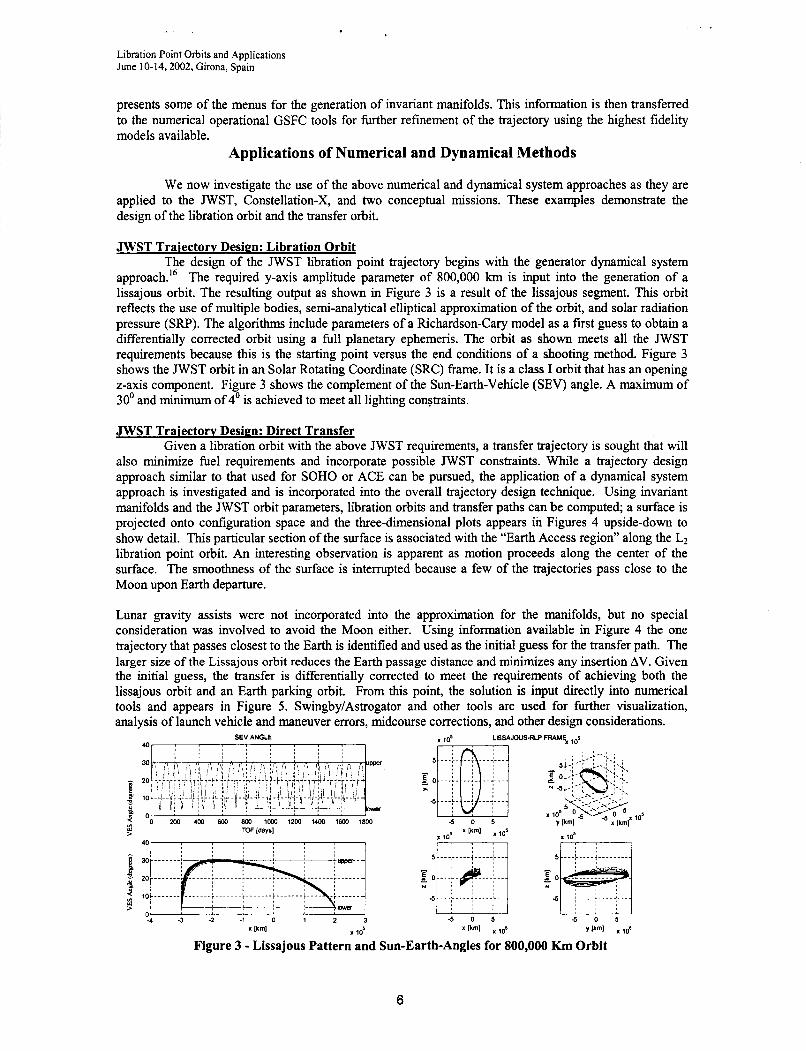
JWST Traiectorv Design: Libration Orbit The design of the JWST libration point trajectory begins with the generator dynamical system
approach.16 The required y-axis amplitude parameter of 800,000 km is input into the generation of a lissajous orbit. The resulting output as shown in Figure 3 is a result of the lissajous segment. This orbit reflects the use of multiple bodies, semi-analytical elliptical approximation of the orbit, and solar radiation pressure (SRP). The algorithms include parameters of a Richardson-Cary model as a first guess to obtain a differentially corrected orbit using a full planetary ephemeris. The orbit as shown meets all the JWST requirements because this is the starting point versus the end conditions of a shooting method. Figure 3 shows the JWST orbit in an Solar Rotating Coordinate (SRC) frame. It is a class I orbit that has an opening z-axis component. Figure 3 shows the complement of the Sun-Earth-Vehicle (SEV) angle. A maximum of 30’ and minimum of 4’ is achieved to meet all lighting constraints.
JWST Traiectorv Design: Direct Transfer Given a libration orbit with the above JWST requirements, a transfer trajectory is sought that will
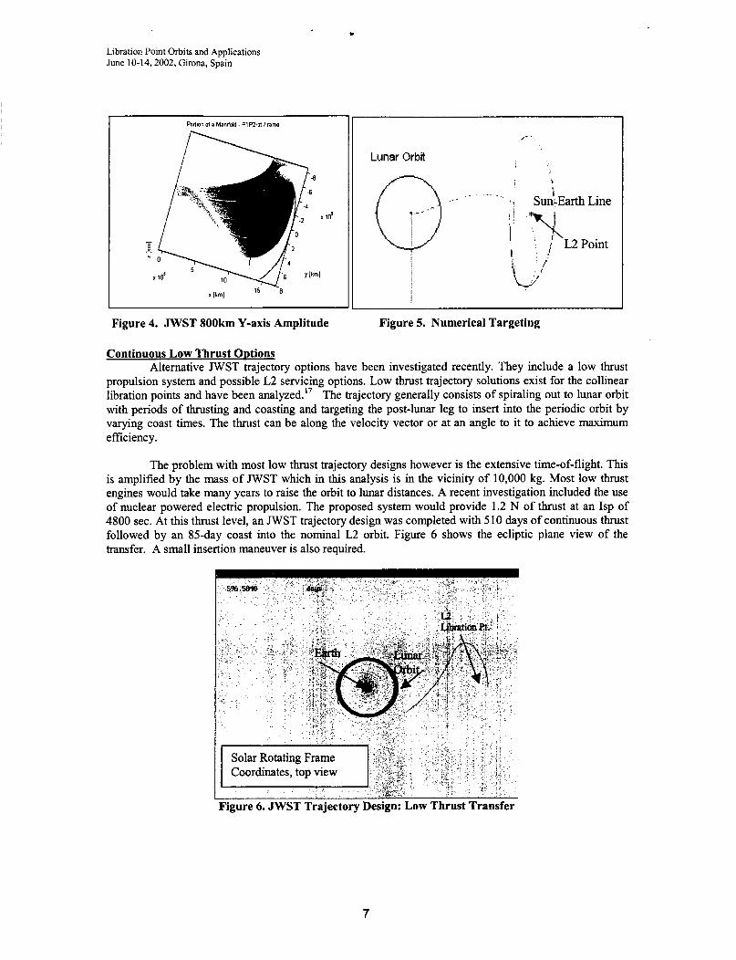
also minimize fuel requirements and incorporate possible JWST constraints. While a trajectory design approach similar to that used for SOH0 or ACE can be pursued, the application of a dynamical system approach is investigated and is incorporated into the overall trajectory design technique. Using invariant manifolds and the JWST orbit parameters, libration orbits and transfer paths can be computed; a surface is projected onto configuration space and the three-dimensional plots appears ih Figures 4 upside-down to show detail. This particular section of the surface is associated with the “Earth Access region” along the L2 libration point orbit. An interesting observation is apparent as motion proceeds along the center of the surface. The smoothness of the surface is interrupted because a few of the trajectories pass close to the Moon upon Earth departure.
Lunar gravity assists were not incorporated into the approximation for the manifolds, but no special consideration was involved to avoid the Moon either. Using information available in Figure 4 the one trajectory that passes closest to the Earth is identified and used as the initial guess for the transfer path. The larger sue of the Lissajous orbit reduces the Earth passage distance and minimizes any insertion AV. Given the initial guess, the transfer is differentially corrected to meet the requirements of achieving both the lissajous orbit and an Earth parking orbit. From this point, the solution is input directly into numerical tools and appears in Figure 5. Swingby/Astrogator and other tools are used for further visualization, analysis of launch vehicle and maneuver errors, midcourse corrections, and other design considerations.
SEV ANGLE LISSAJOUS-RLP FRAME, los 40
30
- 20 5 0 ..-1. __.. -.-.-. - I , , 2. I , , , , ,
I , , -5 _ _ _ L _ _.’ .__,___
P
{ OO m 4w 600 Bm 1m 12w lux) 1600 1800 -5 0 5
5 ToF IdWSl 105 * [kml i 105
op e 20 _ _ _ _ _ _ _ ’ --.... ’.......:..---.-.---- -----..:.-----
;-......;.-...--;-------;.--- -r - - - - - - ’ Y
w 3 10 .--.-.. i ._..._ I
4 - 3 - 2 - 1 0 1 2 3 - 5 0 5 - 5 0 5 x Ikml IO’ [kml vPm1 I 105
Figure 3 - Lissajous Pattern and Sun-Earth-Angles for 800,000 Km Orbit
6
Libration Point Orbits and Applications June 10-14,2002, Girona, Spain
Poltion o f a Manllold - PlPZrol Frame
Lunar Orbt
.- Q- i ~
\ I
s t SunkEarth Line
Figure 4. JWST 800km Y-axis Amplitude Figure 5. Numerical Targeting
Continuous Low Thrust ODtions Alternative JWST trajectory options have been investigated recently. They include a low thrust
propulsion system and possible L2 servicing options. Low thrust trajectory solutions exist for the collinear libration points and have been analyzed.” The trajectory generally consists of spiraling out to lunar orbit with periods of thrusting and coasting and targeting the post-lunar leg to insert into the periodic orbit by varying coast times. The thrust can be along the velocity vector or at an angle to it to achieve maximum efficiency.
The problem with most low thrust trajectory designs however is the extensive time-of-flight. This is amplified by the mass of JWST which in this analysis is in the vicinity of 10,000 kg. Most low thrust engines would take many years to raise the orbit to lunar distances. A recent investigation included the use of nuclear powered electric propulsion. The proposed system would provide 1.2 N of thrust at an Isp of 4800 sec. At this thrust level, an JWST trajectory design was completed with 510 days of continuous thrust followed by an &day coast into the nominal L2 orbit. Figure 6 shows the ecliptic plane view of the transfer. A small insertion maneuver is also required.
~~ ~
Figure 6. JWST Trajectory Design: Low Thrust Transfer
7

. Libration Point Orbits and Applications June 10-14,2002, Girona, Spain
The design of this trajectory was accomplished using the numerical process of Swingby to model the continuous propulsion system, maintain the proper attitude profile, and perform a shooting method to achieve the libration orbit goals. While the DC method was chosen for this analysis, other utilities can be used to optimize transfer time (coast and finite burn sequence) or minimize fuel for the trajectory. Also generator can be used to setup initial conditions for the parking orbit and final targets.
Earth Return / Servicing missions The possibility of L2 servicing brings up numerous scenarios. One such scenario studied recently
is to return JWST to LEO to be serviced at the ISS. Unstable manifolds from the nominal L2 orbit that pass near the Earth are used as initial estimates. The manifold is targeted to meet inclination and dynamic pressure constraints. A large drag apparatus would be used to aerocapture at the Earth. After first perigee at the Earth, an apogee maneuver would be required to retarget perigee to the original 107 km altitude. After three perigees, perigee altitude remains constant and the spacecraft is aerocaptured within 4 days. Figures 7 and 8 show the transfer to and from L2 in the rotating frame and in the inertial frame near the Earth.
Earth
Coordinates, side view
Figure 7. JWST Trajectory Design: Servicing Return with Aerobraking Transfer
I Ill - . I
I -Q. Earth
! Figure 8. JWST Trajectory Design: Servicing Return with Aerobraking Transfer
8

Libration Point Orbits and Applications June 10-14,2002, Girona, Spain
Constellation-X Constellation-X is more challenging. It involves a scientific desire to have four spacecraft in
relative close proximity to one another whilethe transfer design requires a lunar gravity assist The mission separations are not determined as of this date, but initial goals indicate separations of greater than 50km but less than 50,OOOkm. The spacecraft must maintain this separation throughout the mission. Thus part of the trajectory design challenge is to launch two spacecraft from one launch vehicle and perform a lunar gravity assist to attain a libration orbit that meets a relative formation requirement. The mission orbit was chosen primarily to meet the following sky coverage requirement, the mission orbit and attitude constraints must be such that 90% of the sky is accessible at least twice per year, with viewing windows not shorter than 2 weeks in duration; and 100% of the sky is available at least once a year with a minimum viewing window of one week.
The spacecraft will be inserted into the Lissajous orbit via a lunar swingby. The lunar swingby is necessary in order to reduce the amount of onboard AV and the C3 (launch energy) needed from the launch vehicle. Smaller (more negative) values of C3 yield a larger payload capability. In order to increase the number of launch opportunities, a number of phasing loops will be performed prior to the lunar swingby. Figure 9 shows the Constellation-X transfer trajectory and the characteristics of this approach assuming 3 % phasing loops. Different numbers of loops could be considered for various launch days to increase the number of launch opportunities.
Under a current concept, two Constellation-X spacecraft will be placed in a highly eccentric injection orbit by the launch vehicle. Maneuvers will be performed roughly centered on the phasing loop apses, using the spacecraft propulsion system, to properly time the spacecraft's encounter with the moon. The timing and geometry of the lunar encounter will be chosen to allow the spacecraft to be inserted into the L2 Lissajous orbit with little or no maneuver required and still meet separation requirements. The trajectory design was computed using Swingby.
No requirement has been specified regarding the depth or duration of acceptable Earth or lunar shadows. In designing the nominal trajectory, an effort will be made to minimize shadows without significantly increasing total AV during all phases of the mission. However, some shadows may be unavoidable during design, or others maneuver adjustment will be used to mitigate cruise phase (after lunar swingby but prior to lissajous insertion) shadows post-launch. Unacceptable shadows in the lissajous orbit may be avoided through propulsive maneuvers, however no fuel has been budgeted for that purpose.
The total AV required in this particular example is approximately 160 d s e c per spacecraft. This includes correcting for launch vehicle errors, targeting the lunar swingby, mid-course correction maneuvers, Lissajous orbit insertion and station- keeping maneuvers. Table 3 details the AV budget for each spacecraft with a launch that assumes a C3 of - 2.60km2/s2.
may crop up during flight due to contingencies. Phasing loop
Loop orbit
1 .
Figure 9. Constellation-X Transfer Traiectorv
ConceDtual Missions GSFC's Flight Dynamics Analysis Branch performs many future mission studies in the conceptual
phase. One recent analysis included a mission to study the distant geotail between the Earth-Sun L2 point. The investigator wanted to obtain coincident measurements of the geotail over a wide spatial region from L2 to about twice L2. The resulting trajectory design uses the periodic orbits about L2 to initiate slightly perturbed trajectory arcs that all cross into the geotail within a week of each other as shown in figure 10. A mother ship would release 16 small spacecraft into perturbed orbits, each cumulatively 10 d s in along-
9

Libration Point Orbits and Applications June 10-14,2002, Girona, Spain
track AV off the periodic orbit. The mother ship would spend 333 d s e c in AV during the release phase over four days including returning to the periodic orbit. The small spacecrafl would not have any propulsion system.
Solar Rotating Frame I Coordinates, top view
Earth -- _ -
i
f ' &@" Lunar Orbit
\
Figure 10 Conceptual Trajectory Design to Twice L2 Distance
10
Libration Point Orbits and Applications June 10-14,2002, Girona, Spain
LIBRATION FORMATION FLYING In addition to the need for improved numerical and dynamical system approaches to libration
trajectory design, capabilities are required to meet new multiple spacecraft mission goals of interferometer and optical measurements and need to include new methods for operational application to support the trajectory design. As seen in Table 1, there are at least five missions that require formations. In combination with dynamical and improved direct methods, algorithms are being developed for complete ‘system’ control of formation flying spacecraft. These methods employ linear and non-linear feedback control systems that can be managed to analyze cooperative spacecraft. Currently, formation flying spacecraft control is being extensively researched and has been demonstrated autonomously for in low Earth orbit. A growing interest in formation flying satellites demands development and analysis of control and estimation algorithms for stationkeeping and formation maneuvering. This development of controllers, such as discrete linear-quadratic-regulator control or non-linear approaches for formations in the vicinity of the co-linear sun-Earth libration point will be necessary. This development may include an appropriate Kalman filter as well.
Formation flying control can be performed in three ways-centralized, decentralized, or in combinations. With centralized control, one spacecraft or processor calculates and commands the motion of the entire formation. With decentralized control, each spacecraft, with input from the rest of the formation, processes its own control requirements. Speyer first introduced a decentralized linear-quadratic- Gaussian control method2’. Folta and Carpenter applied this work to formation flying satellites, and further expanded it to deal with both time-invariant and time-varying systems*’. Speyer’s method produces identical results to the centralized linear-quadratic-Gaussian control method, and it also minimizes data transmission.
NASA has several distributed spacecraft libration missions planned for the next decade and beyond. The Stellar Imager22 , Constellation-X, and MAXIM will image stars and black holes while TPF will look for planets. They also rely on the capability of correctly modeling the dynamics of the libration region and the inclusion of the formation control method into the overall picture. For example in a recent libration formation flying research using the Stellar Imager mission that uses 31 spacecraft in close formation at L2 as a baseline, the dynamics of the libration region were incorporated into the control state space to ensure accurate modeling and therefore more accurate control results. The modeling of the dynamics creates much more realistic Lissajous orbits than those derived from the circular restricted three- body problem. Also one can numerically compute and output the dynamics matrix, for a single/multiple satellite at each epoch. This matrix is not computed from the pseudopotential but is a monodromy matrix which incorporates the full perturbations and third body ephemeris data.
Stellar Imaper ExamDle Stellar Imager (SI) is a concept for a space-based, UV-optical interferometer. The purpose of the
mission is to view many stars with a sparse aperture telescope in an attempt to better understand the various effects of stars’ magnetic fields, the dynamos that generate them, and the internal structures and dynamics of stars.
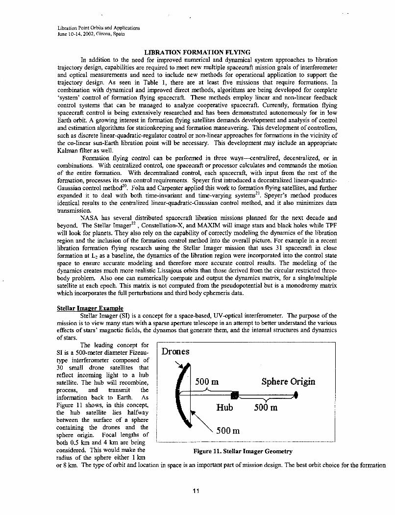
The leading concept for SI is a 500-meter diameter Fizeau- type interferometer composed of 30 small drone satellites that reflect incoming light to a hub satellite. The hub will recombine, process, and transmit the information back to Earth. As Figure 11 shows, in this concept, the hub satellite lies halfway between the surface of a sphere containing the drones .and the sphere origin. Focal lengths of both 0.5 km and 4 km are being considered. This would make the radius of the where either 1 km
Drones
Sphere Origin
Figure 11. Stellar Imager Geometry
or 8 km. The type of orbit and location in space is an important part of mission design. The best orbit choice for the formation
11

Libration Point Orbits and Applications -June 10-14,2002, Girona, Spain
able to cover the entire sky every half year while maintaining an aim perpendicular to the sun. For useful imaging, SI must aim within 10 degrees of perpendicular fiom the sun.
To function properly, SI will need to accommodate a wide range of control functions. In addition to maintaining its desired trajectory around L2, the formation must slew about the sky requiring movement of a few kilometers and attitude adjustments of up to 180 degrees. While imaging, though, the drones must maintain position within 3 nanometers of accuracy in the direction radial from the hub and within 0.5 millimeters of accuracy along the sphere surface. The accuracy required for attitude control while imaging is 5 milli-arcseconds tip and tilt (rotations out of the surface of the sphere). The rotation about the axis radial from the hub (rotation within the sphere) is a much less stringent 10 degrees.
SI Formation Flving Results A common approximation in research of this type models the dynamics ofa satellite in the vicinity
of the sun-earth L2 point using the circular restricted three-body assumptions. These assumptions only account for gravitational forces fiom the sun and Earth. The moon is also included, but not as an independent body. The masses of the earth and moon are combined and assumed to be at the Earth-moon barycenter. The motion of the sun and the Earth-moon barycenter is also assumed to be circular around the system barycenter. There is extensive literature available on the application of linear quadratic regulator (LQR) control to formation flight in the two-body problem (2BP) and also a few examples of its application in the circular-restricted three-body problem (CR3BP). The numerical implementation of this type of control is often difficult because of the assumptions in its original development are based on two-body dynamics, general optimal control theory, and calculus of variations. The most significant of these assumptions is that the nonlinear system dynamics are linearized relative to a constant equilibrium solution. This results in a linear system that assumes constant matrices. In spite of this critical assumption, the available literature includes numerous examples in which this result is extended to time-varying systems, where the system matrices are actually time varying. Although the controller may appear to work on a case-by-case basis, most of the available research on formation flight to date provides no sound mathematical justification for this extension. Furthermore, since the most
controller is violated, it is safe to say that the resulting controller is not truly optimal. To properly apply LQR control to formation flight in the three-dimensional CR3BP, particularly in the vicinity of periodic orbits near L1 and L2, it is necessary to account for the time-varying nature of the linearized dynamics; for a halo orbit, the system matrix is periodic.
This SI analysis uses high fidelity
simulation. This creates much more realistic
x 16 IO'
>.
essential assumption in the development of this 0 0.5 1 1.5 2 0 0.5 1 1.5 2 X X x lo" x lo6
10' 10'
, I <
-1 4.5 0 0.5 1
dynamics based on a dynamical systems y x lo"
Lissajous orbits than those derived from the circular restricted three-body problem. Using Figure 12 Generator Reference Orbit
ephemeris files, we take into account the effects of eccentricity, an independent moon, the other planets of the solar system, and solar radiation pressure. The resulting Lissajous orbit can then be used as a more accurate reference orbit. In addition to providing the reference positions and velocities, the dynamics matrix is also numerically computed at each epoch. The SI reference orbit is shown in Figure 12 with the Earth as the origin. The X coordinate connects the two primary bodies, the 2 coordinate is parallel to their angular velocity of the system, q and the Y coordinate completes a right-handed system.
Three different scenarios make up the SI formation control proble-maintaining the Lissajous orbit, slewing the formation to aim at another star, and reconfiguring the formation to take another snapshot of a star when necessary. Following the Lissajous orbit is not a problem of formation control, but rather a problem of maintaining an orbit. Therefore, only the hub satellite needs simulation to determine the
12

V
1
Libration Point Orbits and Applications June 10-14,2002, Girona, Spain
Focal Slew Hub Length Angle AY(m/s)
0.5 30 1.0705 (km) (deg)
amount of control and fuel needed to maintain a Lissajous orbit. The results can be extended similarly to other satellites in the formation.
Drone 2 Drone 3 1 AV (m/s) A V ( d s )
0.8271 0.8307
Formation Maintenance Results Averaging the determined A V from a dozen simulations, the A V required to keep a satellite in a
Lissajous orbit about L2 for two orbital periods is approximately 0.38 meters per secoAd. A key part of the SI mission is to image many stars. Following a Lissajous orbit around L2, SI could view the entire sky approximately every half-year while slewing about just the radial (x) axis. This maintenance method will also maintain the aiming angle perpendicular to the sun. The formation slewing simulation follows a similar algorithm as the Lissajous orbit simulation. Figure 13 provides an image of the entire SI formation slewing 90 degrees, with a 0.5 km focal length.
0.5 4
90 1.1355 0.9395 0.9587 30 1.2688 1.1189 1.1315
-0 5
(k Drone s/c at beginning
4
Figure 13 SI Slewing Configuration
90 1.8570 2.1907 2.1932
The black dots represent drones at the beginning of the simulation, and the red circles represent drones at the end of the simulation. The hub is the black asterisk at the origin. The upper-right plot illustrates the Golomb'' rectangle formation projected into the x-z plane. The lower-left plot clearly shows the drones slewing 90 degrees about the hub-centered x axis.
The formation slewing simulation runs for one day, with one maneuver per minute (1440 maneuvers), whereas the Lissajous orbit simulation runs for 359 days with one maneuver per day. Table 4 shows the average AV 's for a dozen simulations for the various scenarios. The larger the angle the formation slews through, the more A v is needed. Also, the larger the focal length, the more A V required.
FUTURE MISSION DESIGNS NEEDS
Immoved Tools If one includes search methods and optimization in numerical and dynamical approaches, a full
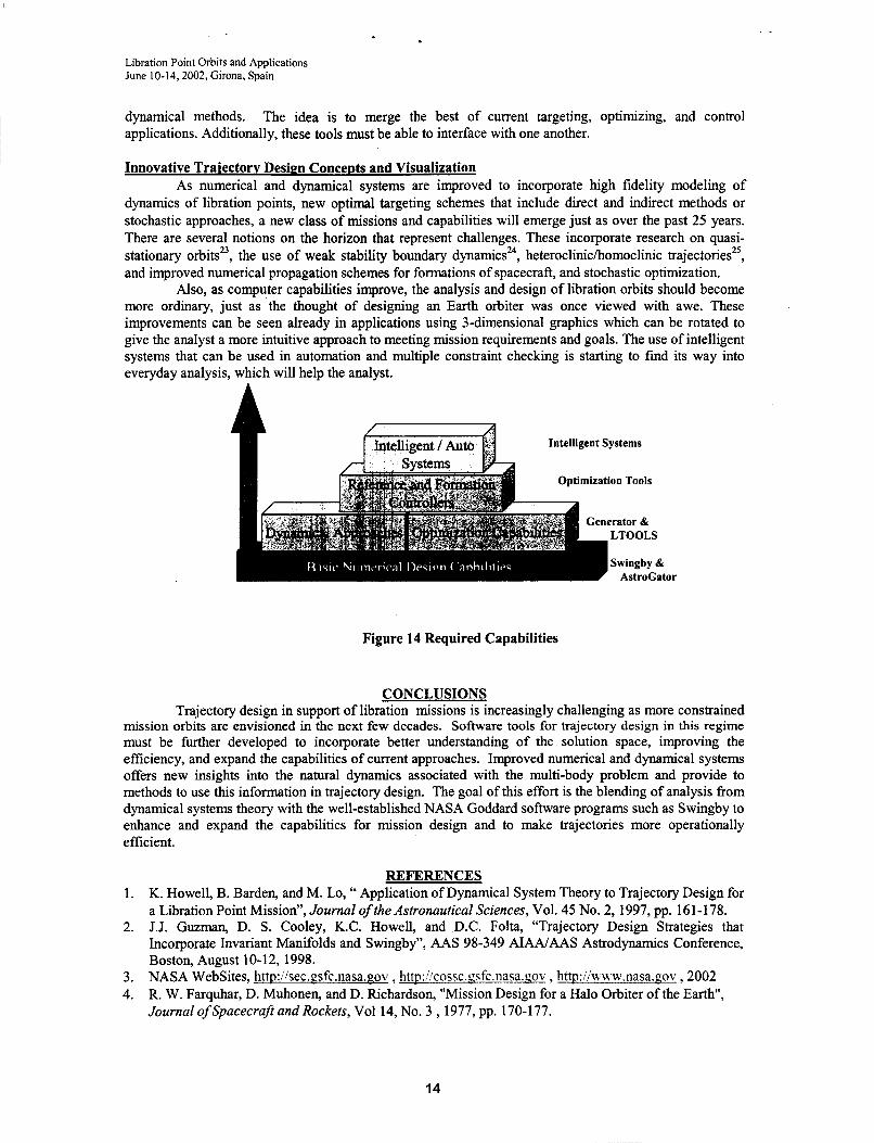
system architecture can be made for design for libration missions that include single and multiple spacecraft, and Human Exploration and Development of Space (HEDS) missions. New search methods, such as genetic and simulated annealing algorithms, combined with indirect and direct optimization techniques can be applied to best meet scientific and HEDS libration formation flying requirements. These tools would provide the best-case scenario for the formation or orbit type, fuel cost, and transfers to minimize overall system cost. While the roadmap is still being worked, the outlook is very promising. Figure 14 gives a possible path to a level that incorporates all the best capabilities of numerical and
13
Libration Point Orbits and Applications June 10-14,2002, Girona, Spain
dynamical methods. applications. Additionally, these tools must be able to interface with one another.
The idea is to merge the best of current targeting, optimizing, and control
Innovative Traiectorv Design Concepts and Visualization As numerical and dynamical systems are improved to incorporate high fidelity modeling of
dynamics of libration points, new optimal targeting schemes that include direct and indirect methods or stochastic approaches, a new class of missions and capabilities will emerge just as over the past 25 years. There are several notions on the horizon that represent challenges. These incorporate research on quasi- stationary orbitsz3, the use of weak stability boundary dynamicsz4, heteroclinic/homoclinic trajectoriesz5, and improved numerical propagation schemes for formations of spacecraft, and stochastic optimization.
Also, as computer capabilities improve, the analysis and design of libration orbits should become more ordinary, just as ‘the thought of designing an Earth orbiter was once viewed with awe. These improvements can be seen already in applications using 3-dimensional graphics which can be rotated to give the analyst a more intuitive approach to meeting mission requirements and goals. The use of intelligent systems that can be used in automation and multiple constraint checking is starting to find its way into everyday analysis, which will help the analyst.
Intelligent Systems
ODtimization Tools
;enerator & LTOOLS
vingby & AstroCator
Figure 14 Required Capabilities
CONCLUSIONS Trajectory design in support of libration missions is increasingly challenging as more constrained
mission orbits are-envisioned in the next few decades. Software tools-for trajectory design in this regime must be further developed to incorporate better understanding of the solution space, improving the efficiency, and expand the capabilities of current approaches. Improved numerical and dynamical systems offers new insights into the natural dynamics associated with the multi-body problem and provide to methods to use this information in trajectory design. The goal of this effort is the blending of analysis from dynamical systems theory with the well-established NASA Goddard software programs such as Swingby to enhance and expand the capabilities for mission design and to make trajectories more operationally efficient.
REFERENCES K. Howell, B. Barden, and M. Lo, “ Application of Dynamical System Theory to Trajectory Design for a Libration Point Mission”, Journal of the Astronautical Sciences, Vol. 45 No. 2, 1997, pp. 161-178. J.J. Guzman, D. S . Cooley, K.C. Howell, and D.C. Folta, “Trajectory Design Strategies that Incorporate Invariant Manifolds and Swingby”, AAS 98-349 AIAAJAAS Astrodynamics Conference, Boston, August 10-12, 1998. NASA WebSites, http:ikec.gsfc.nasa.gov , http:!/cossc.!gfc.nasa.nov , http:i/‘R ww.nasa.gov ,2002 R. W. Farquhar, D. Muhonen, and D. Richardson, “Mission Design for a Halo Orbiter of the Earth”, Journal of Spacecraft and Rockets, Vol 14, No. 3 , 1977, pp. 170-177.
1.
2.
3. 4.
14

Libration Point Orbits and Applications June 10-14,2002, Girona, Spain
5.
6.
7.
8.
9.
10.
11. 12. 13. 14.
15. 16.
17.
18.
19. 20. 21.
22.
23.
24.
25.
26.
R. W. Farquhar, “The Flight of ISEE3/1CE:Origins, Mission History, and a Legacy”, AIAAIAAS Astrodynamics Conference, Boston, AIAA-98-4464, August 10-12, 1998. D. Dunham, S. Jen, C. Roberts, A.Seacord, P.Shearer, D. Folta, and D. Muhonen, “Transfer Trajectory Design for the SOHO Libration Point Mission”, 43rd Congress of the International Astronautical Federation, Washington D.C. 1992. S. Stalos, D. Folta, B. Short, J. Jen, and A. Seacord, “Optimum Transfer to a Large-Amplitude Halo Orbit for the Solar and Heliospheric Observatory (SOHO) Spacecraft, AAS 93-294, Flight Mechanics Symposium, GSFC, 1993. D. Folta and P. Sharer,” Multiple Lunar Flyby Targeting for the WIND Mission”, AAS 96-104, AASIAIAA Space Flight Mechanics Meeting, February 1996, Austin, Tx P. Sharer and T. Harrington, “Trajectory Optimization for the ACE Halo Orbit Mission”, A I M A A S Astrodynamics Specialist Conference, July 1996, San Diego, CA. M. Mesarch, Andrews, “The Maneuver Planning Process For The Microwave Anisotropy Probe (Map), A M A A S Astrodynamics Specialist Conference, Monterey, CA August 5-8, 2002 JWST Website, httd/JWST.asfc.nasa.nov/, Goddard Space Flight Center TPF Website, httd/tDf.iul.nasa.gov/librarvhf book, 2002 ESA Darwin Website, http://scsi.esa.int/, 2002 J. Carrico, C. Schiff, L.Roszman, H.Hooper, D. Folta, and K. Richon, “An Interactive Tool for Design and Support of Lunar, Gravity Assist, and Libration Point Trajectories”, AIAA 93-1126, AIMAHSIASEE Aerospace Design Conference, CA., 1993. Analytical Graphics Incorporated, STK / Astrogator, commercial software package 2002 D. Folta, S Cooley, K Howell, “Trajectory Design Strategies For The NGST L2 Libration Point Mission” , AAS 01-205, AAS Astrodynamcis Conference, CA., 2001. D. Folta et al., “Servicing And Deployment Of National Resources In Sun-Earth Libration Point Orbits”, 53rd International Astronautical Congress, The World Space Congress - 2002, 10-19 Oct 2002 I Houston, Texas M. Houghton, Getting to L1 the Hard Way: Triana’s Launch Options, Libration Point Orbits and Applications June 10-14,2002, Girona, Spain Constellation-X web site, http://constellation.nsfc.nasa.gov ,2002 L. Newman, GSFC Memo, Constelllation-X Trajectory Design and Navigation Report J. L. Speyer, “Computation and Transmission Requirements for a Decentralized Linear-Quadratic- Gaussian Control Problem,” IEEE Transactions on Automatic Control, Vol. AC-24, No. 2, April 1979,
D. Folta, R. Carpenter, and C. Wagner, “Formation Flying with Decentralized Control in Libration Point Orbits”, International Space Symposium, Biarritz, France. June 2000 N. Hamilton, D. Folta, and R. Carpenter, “Formation Flying Satellite Control Around The L2 Sun- Earth Libration Point”, To be presented at the A W AAS Astrodynamics Specialist Conference, Monterey, Ca, August, 2002 E. Belbruno, “ The Dynamical Mechanism of Ballistic Lunar Capture Transfers in the Four Body Problem fiom the Perspective on Invariant Manifolds and Hill’s Region”, Centre De Recerca Maematica, Institut D”Estudis Catalans, No. 270, November 1994 E. Belbruno, “Analytic Estimation of Weak Stability Boundaries and Low Energy Transfers”, Contemporary Mathematics, Vol. 292,2002 M. Lo et al. “New Dynamical Systems Application in Mission Design”, Institute of Geophysics and Planetary Physics, Nov., 1999
pp. 266-269.
15