liberty abs
TRANSCRIPT
PIAGGIO WOULD LIKE TO THANK YOU
for choosing one of its products. We have prepared this manual to help you to get the very best from your vehicle. Please read it carefully before ridingthe vehicle for the first time. It contains information, tips and precautions for using your vehicle It also describes features, details and devices to assureyou that you have made the right choice. We believe that if you follow our suggestions, you will soon get to know your new vehicle well and that it willcontinue to give you satisfactory service for many years to come. This booklet forms an integral part of the vehicle; should the vehicle be sold, it mustbe transferred to the new owner.
Liberty ABS
Ed. 08_07/2016 Cod. 1Q000411 (VI-EN)
The instructions given in this manual are intended to provide a clear, simple guide to using your vehicle; this booklet also details routine maintenanceprocedures and regular checks that should be carried out on the vehicle at an authorised Dealer or Service Centre. The booklet also containsinstructions for simple repairs. Any operations not specifically described in this booklet require the use of special tools and/or particular technicalknowledge: to carry out these operations, refer to any authorised Dealer or Service Centres.
2
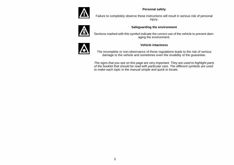
Personal safety
Failure to completely observe these instructions will result in serious risk of personalinjury.
Safeguarding the environment
Sections marked with this symbol indicate the correct use of the vehicle to prevent dam-aging the environment.
Vehicle intactness
The incomplete or non-observance of these regulations leads to the risk of seriousdamage to the vehicle and sometimes even the invalidity of the guarantee.
The signs that you see on this page are very important. They are used to highlight partsof the booklet that should be read with particular care. The different symbols are usedto make each topic in the manual simple and quick to locate.
3

4
INDEX
VEHICLE...................................................................................... 7Dashboard................................................................................ 8Analogue instrument panel....................................................... 9Clock......................................................................................... 11Digital lcd display...................................................................... 12
Setting the hour/minutes function.......................................... 13*MODE* button...................................................................... 14
Keyswitch.................................................................................. 15Locking the steering wheel.................................................... 15Releasing the steering wheel................................................ 16
Switch direction indicators........................................................ 16Horn button............................................................................... 17Light switch............................................................................... 17Start-up button.......................................................................... 18System ABS.............................................................................. 18The immobilizer system............................................................ 20
Keys...................................................................................... 20Immobilizer device enabled indicator led.............................. 20Operation............................................................................... 21Opening the saddle............................................................... 23Opening the saddle to access the helmet compartment in anemergency............................................................................. 23
Identification.............................................................................. 24Rear top box opening................................................................ 25Bag clip..................................................................................... 26
USE.............................................................................................. 27Checks...................................................................................... 28Refuelling.................................................................................. 28Tyre pressure............................................................................ 30Shock absorbers adjustment.................................................... 31Running in................................................................................. 32Starting up the engine............................................................... 32
Precautions........................................................................... 34
Difficult start up......................................................................... 35Stopping the engine.................................................................. 35Stand......................................................................................... 36Automatic transmission............................................................. 37Safe driving............................................................................... 38
MAINTENANCE........................................................................... 41Engine oil level.......................................................................... 42
Engine oil level check............................................................ 42Engine oil top-up................................................................... 43Warning light (insufficient oil pressure)................................. 43Engine oil change.................................................................. 44
Hub oil level.............................................................................. 44Tyres......................................................................................... 46Spark plug dismantlement........................................................ 47Removing the air filter............................................................... 50Checking the brake oil level...................................................... 51
Braking system fluid top up................................................... 51Battery....................................................................................... 53
Use of a new battery............................................................. 54Long periods of inactivity.......................................................... 56Fuses........................................................................................ 57Lamps....................................................................................... 62Front light group........................................................................ 63
Head light adjustment............................................................ 66Front direction indicators........................................................... 67Rear optical unit........................................................................ 67Number plate light..................................................................... 72Rear-view mirrors...................................................................... 73Front disc brake........................................................................ 74Rear drum brake....................................................................... 75Puncture.................................................................................... 75Inactivity of the vehicle.............................................................. 76Cleaning the vehicle.................................................................. 76
5

Troubleshooting........................................................................ 79TECHNICAL DATA...................................................................... 83
Data.......................................................................................... 84SPARE PARTS AND ACCESSORIES........................................ 89
Warnings................................................................................... 90SCHEDULED MAINTENANCE.................................................... 91
Scheduled servicing table......................................................... 92Table of recommended products.............................................. 94
6

Liberty ABS
Chap. 01Vehicle
7
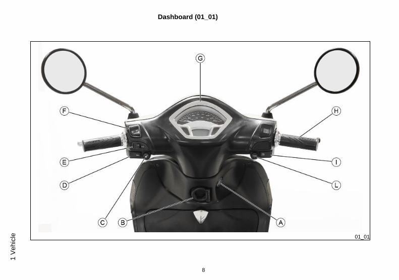
Dashboard (01_01)
01_01
8
1 Ve
hicl
e
A = Ignition switch
B = Bag hook
C = Saddle opening button
D = Horn button
E = Turn indicator switches
F = Headlight switch
G = Instrument panel
H = Throttle grip
I = Starter button
L = MODE key
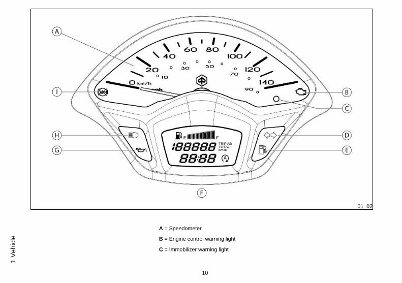
Analogue instrument panel (01_02)
9
1 Vehicle
01_02
A = Speedometer
B = Engine control warning light
C = Immobilizer warning light
10
1 Ve
hicl
e
D = Turn indicator warning light
E = Low fuel warning light
F = Digital display
G = Low oil pressure warning light
H = High-beam warning lights on
I = ABS warning light
01_03
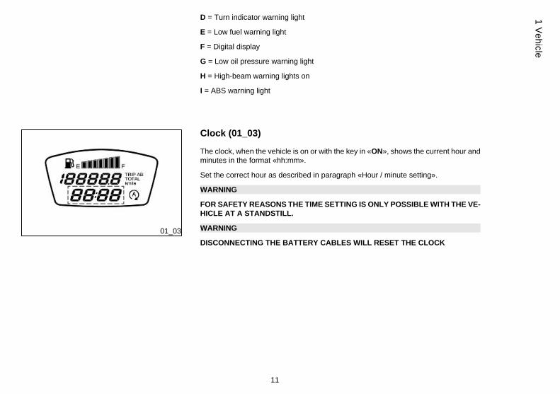
Clock (01_03)
The clock, when the vehicle is on or with the key in «ON», shows the current hour andminutes in the format «hh:mm».
Set the correct hour as described in paragraph «Hour / minute setting».
WARNING
FOR SAFETY REASONS THE TIME SETTING IS ONLY POSSIBLE WITH THE VE-HICLE AT A STANDSTILL.
WARNING
DISCONNECTING THE BATTERY CABLES WILL RESET THE CLOCK
11
1 Vehicle
01_04
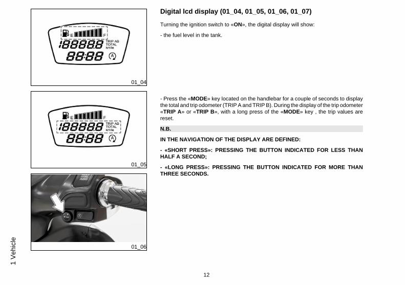
Digital lcd display (01_04, 01_05, 01_06, 01_07)
Turning the ignition switch to «ON», the digital display will show:
- the fuel level in the tank.
01_05
01_06
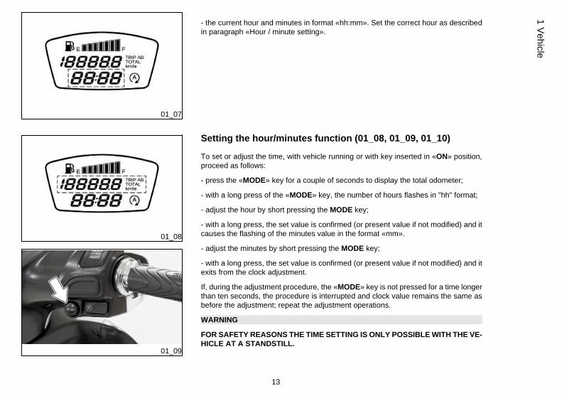
- Press the «MODE» key located on the handlebar for a couple of seconds to displaythe total and trip odometer (TRIP A and TRIP B). During the display of the trip odometer«TRIP A» or «TRIP B», with a long press of the «MODE» key , the trip values arereset.
N.B.
IN THE NAVIGATION OF THE DISPLAY ARE DEFINED:
- «SHORT PRESS»: PRESSING THE BUTTON INDICATED FOR LESS THANHALF A SECOND;
- «LONG PRESS»: PRESSING THE BUTTON INDICATED FOR MORE THANTHREE SECONDS.
12
1 Ve
hicl
e
01_07
- the current hour and minutes in format «hh:mm». Set the correct hour as describedin paragraph «Hour / minute setting».
01_08
01_09
Setting the hour/minutes function (01_08, 01_09, 01_10)
To set or adjust the time, with vehicle running or with key inserted in «ON» position,proceed as follows:
- press the «MODE» key for a couple of seconds to display the total odometer;
- with a long press of the «MODE» key, the number of hours flashes in "hh" format;
- adjust the hour by short pressing the MODE key;
- with a long press, the set value is confirmed (or present value if not modified) and itcauses the flashing of the minutes value in the format «mm».
- adjust the minutes by short pressing the MODE key;
- with a long press, the set value is confirmed (or present value if not modified) and itexits from the clock adjustment.
If, during the adjustment procedure, the «MODE» key is not pressed for a time longerthan ten seconds, the procedure is interrupted and clock value remains the same asbefore the adjustment; repeat the adjustment operations.
WARNING
FOR SAFETY REASONS THE TIME SETTING IS ONLY POSSIBLE WITH THE VE-HICLE AT A STANDSTILL.
13
1 Vehicle

01_10
WARNING
DISCONNECTING THE BATTERY CABLES WILL RESET THE CLOCK
01_11
01_12
*MODE* button (01_11, 01_12)
The «MODE» key, located on the right side of the handlebar, allows to:
- alternate the display of the total or trip odometer with short pressures ;
- alternate the trip odometer when shown, with a long pressure;
- access the time adjusting mode, when the total odometer is shown, with a long pres-sure;
- set the measuring unit of the odometer between kilometres «Km» or miles «mile»;to proceed with this setting, display the total odometer and put the ignition switch to«OFF». Keep the «MODE» key pressed and put the ignition switch to «ON», releasewithin 2 seconds the «MODE» key.
14
1 Ve
hicl
e

01_13
Keyswitch (01_13)
SWITCH POSITIONS
ON«1»: Ready to start position, non-extractable key, mechanical anti-theft devicedisabled. Saddle opening and case opening possible.
OFF «2»: Ignition disabled, non-extractable key, mechanical anti-theft device disa-bled. Saddle opening and case opening possible.
CLOSE «3»: Ignition disabled, extractable key, mechanical anti-theft device disabled.Saddle opening and case opening disabled.
LOCK «4»: Ignition disabled, extractable key, mechanical anti-theft device enabled.Saddle opening and case opening disabled.
01_14
Locking the steering wheel (01_14)
Turn the handlebar to the left (as far as it will go), turn the key to «LOCK» and removethe key.
CAUTION
NEVER TURN THE KEY TO «LOCK» OR «OFF» WHILE RIDING.
15
1 Vehicle

01_15
Releasing the steering wheel (01_15)
Reinsert the key and turn it to «OFF».
CAUTION
NEVER TURN THE KEY TO «LOCK» OR «OFF» WHILE RIDING.
01_16
Switch direction indicators (01_16)
Move the lever «A» of the turn indicators switch to the left, to position «1» to turn theleft turn indicators on. the lever automatically goes back to «0».
Move the lever «A» of the turn indicators switch to the right, to position «2» to turn theright turn indicators on. the lever automatically goes back to «0».
Press the lever «A» of the switch on «0» to turn the turn indicators off.
16
1 Ve
hicl
e

01_17
Horn button (01_17)
Press the button to sound the horn.
01_18
Light switch (01_18)
Place the light switch «A» to «0» to turn the high beam lights on.
Place the light switch «A» to «1» to turn the low beam lights on.
The position «2» activates the high beam flashing; the switch automatically goes backto «1».
CAUTION
DO NOT REST OR TRANSPORT OBJECTS AND/OR CLOTHING ON TOP OF THEFRONT LIGHT ASSEMBLY WITH THE LIGHT ON OR JUST TURNED OFF. FAIL-URE TO OBSERVE THIS PRECAUTION MAY CAUSE THE GLASS TO OVERHEATAND CONSEQUENTLY MELT.
17
1 Vehicle
01_19
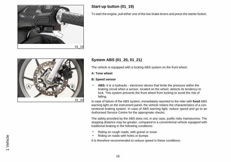
Start-up button (01_19)
To start the engine, pull either one of the two brake levers and press the starter button.
01_20
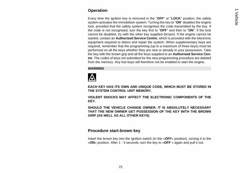
System ABS (01_20, 01_21)
The vehicle is equipped with a locking ABS system on the front wheel.
A: Tone wheel
B: Speed sensor
• ABS: It is a hydraulic - electronic device that limits the pressure within thebraking circuit when a sensor, located on the wheel, detects its tendency tolock. This system prevents the front wheel from locking to avoid the risk offalling.
In case of failure of the ABS system, immediately reported to the rider with fixed ABSwarning light on the instrument panel, the vehicle retains the characteristics of a con-ventional braking system. In case of ABS warning light, reduce speed and go to anAuthorised Service Centre for the appropriate checks.
The safety provided by the ABS does not, in any case, justify risky manoeuvres. Thestopping distance may be greater, compared to a conventional vehicle equipped withtraditional braking in the following conditions:
• Riding on rough roads, with gravel or snow• Riding on roads with holes or bumps
It is therefore recommended to reduce speed in these conditions.
18
1 Ve
hicl
e

AT VERY LOW SPEEDS (LESS THAN 5 KM/H) THE ABS SYSTEM IS DISABLED.
IT IS RECOMMENDED TO PAY ATTENTION THEREFORE IN CASES OF BRAK-ING IN LOW GRIP CONDITIONS AT LOW SPEED (FOR EXAMPLE BRAKING ONGARAGE FLOOR TILES AFTER HAVING RIDDEN ON WET ROADS OR SIMILARSITUATIONS)
01_21
The warning light flashes in the following cases:
• with the panel «ON» and running until reaching 5 Km/h speed, then it turnsoff indicating the correct engagement of the system
• During deceleration to below 5 Km/h.
WARNING
IF THE ABS WARNING LIGHT FLASHES WHEN RIDING OVER 5 KM/H, IT INDI-CATES A MALFUNCTION OF THE ABS SYSTEM AND CONSEQUENTLY THEREDUCTION OF THE EFFICIENCY OF THE BRAKING SYSTEM. IMMEDIATELYCONTACT AN AUTHORISED SERVICE CENTRE.
IT IS NORMAL THAT THE WARNING LIGHT FLASHES WITH THE VEHICLE ATSTANDSTILL AND THE PANEL «ON».
THE ACTIVATION OF THE «CONTINUOUS» WARNING LIGHT INDICATES ASYSTEM FAILURE. IMMEDIATELY CONTACT AN AUTHORISED SERVICE CEN-TRE.
19
1 Vehicle

The immobilizer system
In order to enhance theft protection, the vehicle is equipped with a «PIAGGIO IMMO-BILIZER » electronic engine locking device that is activated automatically when theignition key is removed. Upon start-up, the «PIAGGIO IMMOBILIZER» system checksthe starter key, and only if this key is recognised will the Immobiliser system allow thevehicle to be started.
01_22
Keys (01_22)
The vehicle is supplied with two types of keys. The «A» key with a brown grip and the"MASTER" key. Only a single copy of this key is supplied, which is necessary to pro-gram all your other keys and for your dealer to perform some maintenance operations.We therefore recommend that it be used only under exceptional circumstances. Theblue key «B» (single copy supplied) is used for normal operations and for start-up.
WARNING
THE LOSS OF THE BROWN KEY PREVENTS LATER REPAIRS TO THE "PIAG-GIO IMMOBILIZER" SYSTEM AND TO THE ENGINE CONTROL UNIT.
01_23
Immobilizer device enabled indicator led (01_23)
Activation of the «PIAGGIO IMMOBILIZER» system is signalled by a flashing warninglight (see the "Analogue instrument cluster" section).
In order to reduce battery discharge, the indicator LED turns off automatically after 48hours of uninterrupted functioning.
Should the system fail, different LED flashing patterns will provide the AuthorisedService Centre with information on the type of fault detected.
20
1 Ve
hicl
e
Operation
Every time the ignition key is removed in the "OFF" or "LOCK" position, the safetysystem activates the immobilizer system. Turning the key to "ON" disables the enginelock, provided that the safety system recognises the code transmitted by the key. Ifthe code is not recognised, turn the key first to "OFF" and then to "ON"; if the lockcannot be disabled, try with the other key supplied (brown). If the engine cannot bestarted, contact an Authorised Service Centre, which is provided with the electronicequipment required to detect and repair the system. When supplementary keys arerequired, remember that the programming (up to a maximum of three keys) must beperformed on all the keys whether they are new or already in your possession. Takethe key with the brown grip and all the keys supplied to an Authorised Service Cen-tre. The codes of keys not submitted for the new programming procedure are deletedfrom the memory. Any lost keys will therefore not be enabled to start the engine.
WARNING
EACH KEY HAS ITS OWN AND UNIQUE CODE, WHICH MUST BE STORED INTHE SYSTEM CONTROL UNIT MEMORY.
VIOLENT SHOCKS MAY AFFECT THE ELECTRONIC COMPONENTS OF THEKEY.
SHOULD THE VEHICLE CHANGE OWNER, IT IS ABSOLUTELY NECESSARYTHAT THE NEW OWNER GET POSSESSION OF THE KEY WITH THE BROWNGRIP (AS WELL AS ALL OTHER KEYS)
Procedure start-brown key
Insert the brown key into the ignition switch (in the «OFF» position), turning it to the«ON» position. After 1 - 3 seconds, turn the key to «OFF » again and pull it out.
21
1 Vehicle

Intermediate step-blu key
After extracting the brown key, insert the blue key within 10 seconds and promptly turnit to «ON». After 1 - 3 seconds, turn the key to «OFF» again and pull it out.
In this way, a maximum of 3 blue keys can be programmed by repeating the aboveprocedure and keeping the indicated times.
Final step-brown key
After extracting the last blue key, insert the brown key again and turn it to «ON» (carryout this operation within 10 seconds after extracting the previous key). Leave it in thisposition for 1 to 3 seconds and return it to «OFF».
Proper programming check
Insert the brown key, disabling the transponder (i.e., by tilting the key hood by 90°),and turn the key to the «ON» position. Perform the engine starter operation. Ensurethat the engine does not start. Insert the blue key and repeat the start-up operation.Check that engine starts.
WARNING
IF THE ENGINE STARTS WITH THE BROWN KEY (AND WITH A DISABLEDTRANSPONDER) OR IF DURING THE PROGRAMMING A WRONG STEP HASBEEN CARRIED OUT, IT IS NECESSARY TO REPEAT THE PROCESS FROM THEBEGINNING.
22
1 Ve
hicl
e

01_24
Opening the saddle (01_24, 01_25)
To open the saddle, place the ignition switch on «OFF» or «ON».
01_25
Press the saddle opening button and lift the saddle.
01_26
Opening the saddle to access the helmet compartment in anemergency (01_26, 01_27)
If there is no battery power supply, proceed as following:
- Put the ignition switch to «OFF» and press it to open the front case hatch.
23
1 Vehicle

01_27
- Pull the lever located inside the case to the top to open the saddle.
Identification (01_28, 01_29)
The identification numbers consist of a prefix stamped on the chassis and on the en-gine, followed by a number. They must be quoted when ordering spare parts. Werecommend that you check that the prefix and frame number stamped on the vehiclecorrespond with those in the vehicle documents.
CAUTION
PLEASE REMIND THAT ALTERING IDENTIFICATION REGISTRATION NUM-BERS CAN LEAD TO SERIOUS PENAL SANCTIONS (IMPOUNDING OF THEVEHICLE, ETC.).
24
1 Ve
hicl
e
01_28
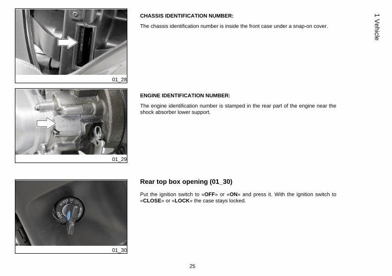
CHASSIS IDENTIFICATION NUMBER:
The chassis identification number is inside the front case under a snap-on cover.
01_29
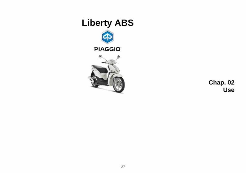
ENGINE IDENTIFICATION NUMBER:
The engine identification number is stamped in the rear part of the engine near theshock absorber lower support.
01_30
Rear top box opening (01_30)
Put the ignition switch to «OFF» or «ON» and press it. With the ignition switch to«CLOSE» or «LOCK» the case stays locked.
25
1 Vehicle

01_31
Bag clip (01_31)
To use the bag hook mounted on the leg shield back plate it must be turned towardsthe saddle.
CAUTION
Maximum applicable load: 1.5 kg
26
1 Ve
hicl
e
Liberty ABS
Chap. 02Use
27
02_01
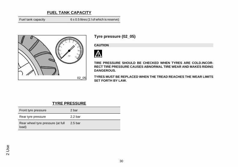
Checks (02_01)
Before using the vehicle, check:
1. That the fuel tank is full.
2. Rear hub oil level.
3. Engine oil level (see the «Engine oil level» section).
4. That the tyres are properly inflated.
5. The correct functioning of headlights, rear light and turn indicators.
6. The correct functioning of front and rear brakes.
02_02
Refuelling (02_02, 02_03, 02_04)
Top up the fuel tank «A» with unleaded petrol.
When the fuel reaches the low fuel level, the warning light on the instrument panellights up.
CAUTION
SHUT OFF THE ENGINE BEFORE REFUELLING WITH PETROL. PETROL ISHIGHLY FLAMMABLE. DO NOT LET PETROL SPILL FROM THE TANK OR WHILEREFUELLING.
CAUTION
UPON REFILLING MAKE SURE TO COMPLETELY ENTER THE GUN INTO THETANK MOUTH TO AVOID ANY FUEL LEAKAGE WHICH COULD LEAD DAMAGES
28
2 U
se

02_03
TO PLASTIC ELEMENTS AND DANGEROUS CONTACTS WITH VEHICLE HOTPARTS.
CAUTION
DO NOT BRING NAKED FLAMES OR CIGARETTES NEAR THE MOUTH OF THEFUEL TANK: FIRE HAZARD. ALSO AVOID INHALING HARMFUL VAPOURS.
CAUTION
ALWAYS USE PETROL WITH A MAXIMUM OF 10% BIOETHANOL CONTENT(E10).
DO NOT USE PETROL WITH AN ETHANOL CONTENT HIGHER THAN 10%; THISUSE COULD DAMAGE THE FUEL SYSTEM COMPONENTS AND/OR COMPRO-MISE ENGINE PERFORMANCE.
02_04
WARNING
THE WARNING LIGHT INDICATES THAT THE RESIDUAL QUANTITY OF FUELREACHES ABOUT 1 LITRE, IMMEDIATELY REFILL THE TANK.
29
2 Use
FUEL TANK CAPACITYFuel tank capacity 6 ± 0.5 litres (1 l of which is reserve)
02_05
Tyre pressure (02_05)
CAUTION
TIRE PRESSURE SHOULD BE CHECKED WHEN TYRES ARE COLD.INCOR-RECT TIRE PRESSURE CAUSES ABNORMAL TIRE WEAR AND MAKES RIDINGDANGEROUS.
TYRES MUST BE REPLACED WHEN THE TREAD REACHES THE WEAR LIMITSSET FORTH BY LAW.
TYRE PRESSUREFront tyre pressure 2 bar
Rear tyre pressure 2.2 bar
Rear wheel tyre pressure (at fullload)
2.5 bar
30
2 U
se

TYRESFront tire Tubeless, 90/80 - 16" 51J
Rear tire Tubeless, 100/80 - 14" 54J
02_06
02_07
Shock absorbers adjustment (02_06, 02_07)
The spring preload is adjustable into 5 different settings by turning the adjuster ringon the bottom of the shock absorbers with a specific wrench for shock absorbers.
Position 1: minimum pre-load: rider only
Position 2 medium preloading: rider only
Position 3 medium preloading: rider and passenger
Position 4 medium preloading: rider and passenger
Position 5: maximum preloading: rider, passenger, and luggage.
Spring preloading increases by turning the ring nut towards «A», but decreases if thering nut is turned towards «B».
CAUTION
RIDING THE VEHICLE WITH THE SPRING PRELOADING NOT CORRECTLY SETFOR THE RIDER AND POSSIBLE PASSENGER, COULD REDUCE THE COM-FORT OF THE RIDE AND THE PRECISION OF THE STEERING.
31
2 Use
WARNING
WE RECOMMEND WEARING GLOVES WHILE CARRYING OUT THIS OPERA-TION IN ORDER TO AVOID INJURIES.
02_08
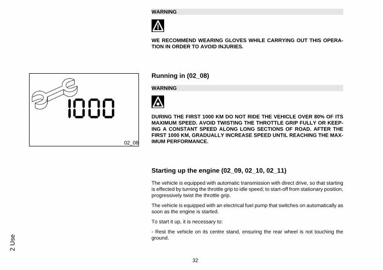
Running in (02_08)
WARNING
DURING THE FIRST 1000 KM DO NOT RIDE THE VEHICLE OVER 80% OF ITSMAXIMUM SPEED. AVOID TWISTING THE THROTTLE GRIP FULLY OR KEEP-ING A CONSTANT SPEED ALONG LONG SECTIONS OF ROAD. AFTER THEFIRST 1000 KM, GRADUALLY INCREASE SPEED UNTIL REACHING THE MAX-IMUM PERFORMANCE.
Starting up the engine (02_09, 02_10, 02_11)
The vehicle is equipped with automatic transmission with direct drive, so that startingis effected by turning the throttle grip to idle speed; to start-off from stationary position,progressively twist the throttle grip.
The vehicle is equipped with an electrical fuel pump that switches on automatically assoon as the engine is started.
To start it up, it is necessary to:
- Rest the vehicle on its centre stand, ensuring the rear wheel is not touching theground.
32
2 U
se

- Keep the throttle grip to idle speed.
02_09
- Insert the key into the ignition key and turn it to «ON».
02_10
- Wait for the engine control telltale light to turn off.
33
2 Use
02_11
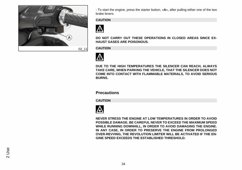
- To start the engine, press the starter button, «A», after pulling either one of the twobrake levers.
CAUTION
DO NOT CARRY OUT THESE OPERATIONS IN CLOSED AREAS SINCE EX-HAUST GASES ARE POISONOUS.
CAUTION
DUE TO THE HIGH TEMPERATURES THE SILENCER CAN REACH, ALWAYSTAKE CARE, WHEN PARKING THE VEHICLE, THAT THE SILENCER DOES NOTCOME INTO CONTACT WITH FLAMMABLE MATERIALS, TO AVOID SERIOUSBURNS.
Precautions
CAUTION
NEVER STRESS THE ENGINE AT LOW TEMPERATURES IN ORDER TO AVOIDPOSSIBLE DAMAGE. BE CAREFUL NEVER TO EXCEED THE MAXIMUM SPEEDWHILE RUNNING DOWNHILL, IN ORDER TO AVOID DAMAGING THE ENGINE.IN ANY CASE, IN ORDER TO PRESERVE THE ENGINE FROM PROLONGEDOVER-REVVING, THE REVOLUTION LIMITER WILL BE ACTIVATED IF THE EN-GINE SPEED EXCEEDS THE ESTABLISHED THRESHOLD.
34
2 U
se

WARNING
AFTER A LONG DISTANCE COVERED AT THE MAXIMUM SPEED, DO NOT STOPTHE ENGINE IMMEDIATELY, BUT LET IT RUN AT IDLE FOR A FEW SECONDS.
Difficult start up
In the rare case of engine flooding, to facilitate start-up, it is possible to try to put thevehicle into action with the gas hand grip partially or completely open. It is howevernecessary, once the engine is started, to take your vehicle to an Authorised ServiceCentre to determine the cause of this problem and to re-establish the vehicle properfunctioning.
02_12
Stopping the engine (02_12)
Stop acceleration, then turn the key switch to «OFF » to stop the engine (extractablekey).
CAUTION
DUE TO THE HIGH TEMPERATURES THE CATALYTIC CONVERTER CANREACH, ALWAYS TAKE CARE, WHEN PARKING THE VEHICLE, THAT THE SI-LENCER DOES NOT COME INTO CONTACT WITH FLAMMABLE MATERIALS,TO AVOID SERIOUS BURNS.
35
2 Use
02_13
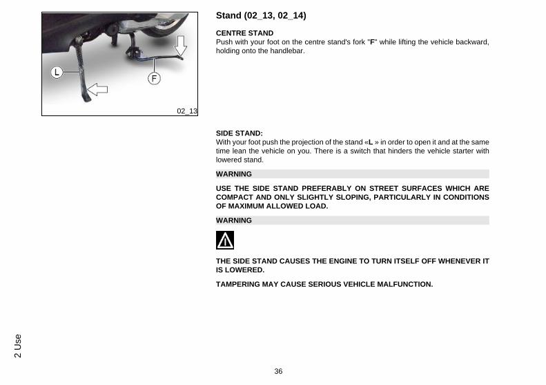
Stand (02_13, 02_14)
CENTRE STANDPush with your foot on the centre stand's fork "F" while lifting the vehicle backward,holding onto the handlebar.
SIDE STAND:With your foot push the projection of the stand «L » in order to open it and at the sametime lean the vehicle on you. There is a switch that hinders the vehicle starter withlowered stand.
WARNING
USE THE SIDE STAND PREFERABLY ON STREET SURFACES WHICH ARECOMPACT AND ONLY SLIGHTLY SLOPING, PARTICULARLY IN CONDITIONSOF MAXIMUM ALLOWED LOAD.
WARNING
THE SIDE STAND CAUSES THE ENGINE TO TURN ITSELF OFF WHENEVER ITIS LOWERED.
TAMPERING MAY CAUSE SERIOUS VEHICLE MALFUNCTION.
36
2 U
se
02_14
CAUTION
THE SIDE STAND IS DESIGNED TO SUPPORT THE VEHICLE WEIGHT, IT IS NOTSUITABLE TO ALSO SUPPORT THE RIDER OR PASSENGER WEIGHT.
02_15
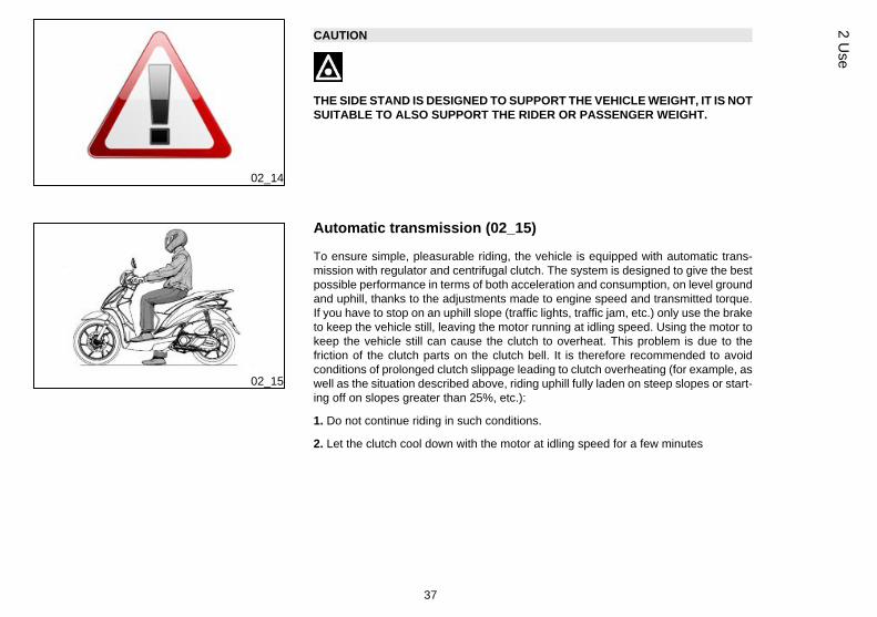
Automatic transmission (02_15)
To ensure simple, pleasurable riding, the vehicle is equipped with automatic trans-mission with regulator and centrifugal clutch. The system is designed to give the bestpossible performance in terms of both acceleration and consumption, on level groundand uphill, thanks to the adjustments made to engine speed and transmitted torque.If you have to stop on an uphill slope (traffic lights, traffic jam, etc.) only use the braketo keep the vehicle still, leaving the motor running at idling speed. Using the motor tokeep the vehicle still can cause the clutch to overheat. This problem is due to thefriction of the clutch parts on the clutch bell. It is therefore recommended to avoidconditions of prolonged clutch slippage leading to clutch overheating (for example, aswell as the situation described above, riding uphill fully laden on steep slopes or start-ing off on slopes greater than 25%, etc.):
1. Do not continue riding in such conditions.
2. Let the clutch cool down with the motor at idling speed for a few minutes
37
2 Use

Safe driving (02_16)
WARNING
SOME SIMPLE TIPS ARE PROVIDED BELOW WHICH WILL ENABLE YOU TOUSE YOUR VEHICLE ON A DAILY BASIS MORE EASILY AND SAFELY. <.
02_16
Your ability and your knowledge of the vehicle form the basis of safe riding. We rec-ommend trying out the vehicle in traffic-free zones to get to know your vehiclecompletely.ALWAYS RIDE WITHIN YOUR LIMITS
1. Before riding off, remember to put the helmet on and fasten it correctly.
2.Reduce speed on rough roads and ride with caution.
3.Remember that after riding on a long stretch of wet road without using the brakes,braking can be poor at the beginning. Under these conditions, it is a good idea tooperate the brakes from time to time.
4.Do not brake hard on wet, unsurfaced or slippery roads.
5.If you have to brake, use both brakes in order to spread the braking action betweenboth wheels.
6.Avoid riding off by mounting the scooter when it is resting on its support. In any case,the rear wheel should not be turning when it comes into contact with the ground, inorder to avoid abrupt departures.
7.If the vehicle is used on roads covered with sand, mud, snow mixed with salt, etc.,clean brake discs frequently with a mild detergent in order to avoid the formation ofabrasive substances in the holes, which could result in early wear of the brake pads.
8.Remember that any change that modifies the vehicle's performance, such as tam-pering with original structural parts, renders the vehicle not conforming to the approvedtype and therefore dangerous to ride.
38
2 U
se
CAUTION
RIDING UNDER THE INFLUENCE OF ALCOHOL, DRUGS OR CERTAIN MEDI-CINES CAN BE EXTREMELY DANGEROUS FOR ONESELF AND FOR OTHERS.
CAUTION
ANY ELABORATION THAT MODIFIES THE VEHICLE'S PERFORMANCES, SUCHAS TAMPERING WITH ORIGINAL STRUCTURAL PARTS IS STRICTLY FORBID-DEN BY LAW, AND RENDERS THE VEHICLE NO LONGER CONFORMING TOTHE APPROVED TYPE AND DANGEROUS FOR RIDING.
39
2 Use

40
2 U
se

Liberty ABS
Chap. 03Maintenance
41

Engine oil level
Four stroke engine oil is used in the engines in order to lubricate the timing bodies,the bench bearings and the head-engine block-piston assembly. An insufficientquantity of oil can seriously damage the engine. In all four-stroke engines, a lossof efficiency in oil performance and certain consumption should be considered normal.Consumption can particularly reflect the conditions of use (i.e: when driving at 'fullacceleration' all the time, oil consumption increases). The replacement intervals pro-vided for by the maintenance programme are defined depending on the total contentof oil in the engine and the average consumption measured following standardisedmethods. In order to prevent any problems, we recommend checking oil levelmore frequently than indicated in the Scheduled Maintenance table or beforesetting off on long journeys. The vehicle is, however, equipped with an oil pres-sure warning light on the instrument cluster.
03_01
Engine oil level check (03_01, 03_02)
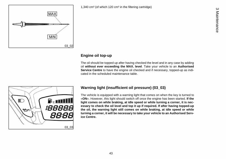
Every time the vehicle is used, visually inspect the level of the engine oil when theengine is cold (after completely unscrewing the oil cap/dipstick). The oil level shouldbe somewhere between the MAX and MIN index marks on the level rod; «A»; whilethe oil is being checked, the vehicle must be resting on its centre stand on an even,horizontal surface.
If the check is carried out after the vehicle has been used, and therefore with a hotengine, the level will be lower; in order to carry out a correct check, wait at least 10minutes after the engine has been stopped so as to get the correct level.
Recommended productsEngine oil
Synthetic-based lubricant for four stroke engines.SAE 10W-40, JASO MA, MA2 - API SL - ACEA A3
CharacteristicEngine oil quantity
42
3 M
aint
enan
ce
03_02
1,340 cm³ (of which 120 cm³ in the filtering cartridge)
Engine oil top-up
The oil should be topped up after having checked the level and in any case by addingoil without ever exceeding the MAX. level. Take your vehicle to an AuthorisedService Centre to have the engine oil checked and if necessary, topped-up as indi-cated in the scheduled maintenance table.
03_03
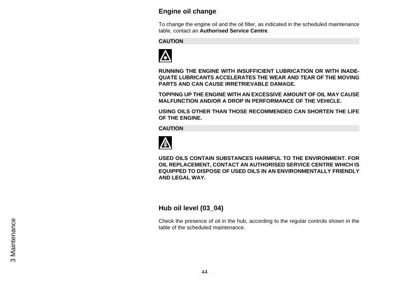
Warning light (insufficient oil pressure) (03_03)
The vehicle is equipped with a warning light that comes on when the key is turned to«ON». However, this light should switch off once the engine has been started. If thelight comes on while braking, at idle speed or while turning a corner, it is nec-essary to check the oil level and top it up if required. If after having topped-upthe oil, the warning light still comes on while braking, at idle speed or whileturning a corner, it will be necessary to take your vehicle to an Authorised Serv-ice Centre.
43
3 Maintenance
Engine oil change
To change the engine oil and the oil filter, as indicated in the scheduled maintenancetable, contact an Authorised Service Centre.
CAUTION
RUNNING THE ENGINE WITH INSUFFICIENT LUBRICATION OR WITH INADE-QUATE LUBRICANTS ACCELERATES THE WEAR AND TEAR OF THE MOVINGPARTS AND CAN CAUSE IRRETRIEVABLE DAMAGE.
TOPPING UP THE ENGINE WITH AN EXCESSIVE AMOUNT OF OIL MAY CAUSEMALFUNCTION AND/OR A DROP IN PERFORMANCE OF THE VEHICLE.
USING OILS OTHER THAN THOSE RECOMMENDED CAN SHORTEN THE LIFEOF THE ENGINE.
CAUTION
USED OILS CONTAIN SUBSTANCES HARMFUL TO THE ENVIRONMENT. FOROIL REPLACEMENT, CONTACT AN AUTHORISED SERVICE CENTRE WHICH ISEQUIPPED TO DISPOSE OF USED OILS IN AN ENVIRONMENTALLY FRIENDLYAND LEGAL WAY.
Hub oil level (03_04)
Check the presence of oil in the hub, according to the regular controls shown in thetable of the scheduled maintenance.
44
3 M
aint
enan
ce
WARNING
FOR THE REGULAR CHECK OF THE HUB OIL LEVEL SHOWN IN THE SCHED-ULED MAINTENANCE TABLE, CONTACT AN Authorised Service Centre.
FOR THE CONTROLS OF THE HUB OIL LEVEL THAT ARE NOT PREDETER-MINED BY THE SCHEDULED MAINTENANCE TABLE, OPERATE AS DESCRI-BED.
03_04
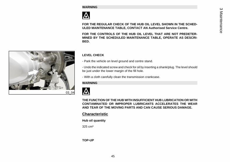
LEVEL CHECK
- Park the vehicle on level ground and centre stand.
- Undo the indicated screw and check for oil by inserting a shank/plug. The level shouldbe just under the lower margin of the fill hole.
- With a cloth carefully clean the transmission crankcase.
WARNING
THE FUNCTION OF THE HUB WITH INSUFFICIENT HUB LUBRICATION OR WITHCONTAMINATED OR IMPROPER LUBRICANTS ACCELERATES THE WEARAND TEAR OF THE MOVING PARTS AND CAN CAUSE SERIOUS DAMAGE.
CharacteristicHub oil quantity
325 cm³
TOP-UP
45
3 Maintenance

If necessary carry out the top-up, DO NOT use the vehicle and contact an Author-ised Service Centre.
CAUTION
USED OILS CONTAIN SUBSTANCES HARMFUL TO THE ENVIRONMENT. FOROIL REPLACEMENT, CONTACT AN AUTHORISED SERVICE CENTRE WHICH ISEQUIPPED TO DISPOSE OF USED OILS IN AN ENVIRONMENTALLY FRIENDLYAND LEGAL WAY.
Recommended productsLubricant for gearboxes and transmissions
Lubricant for gearboxes and transmissions.SAE 80W/90, APIGL4
03_05
Tyres (03_05)
Periodically check the inflation pressure of each tyre (when cold).Tyres are fitted with wear indicators; tyres should be replaced as soon as these indi-cators become visible on the tyre tread. Also check that the tyres do not show signsof splitting at the sides or irregular tread wear; If this occurs, go to an authorised work-shop or at least a workshop adequately equipped to remove and refit tyres.
CAUTION
TIRE PRESSURE SHOULD BE CHECKED WHEN TYRES ARE COLD.INCOR-RECT TIRE PRESSURE CAUSES ABNORMAL TIRE WEAR AND MAKES RIDINGDANGEROUS.
46
3 M
aint
enan
ce

TYRES MUST BE REPLACED WHEN THE TREAD REACHES THE WEAR LIMITSSET FORTH BY LAW.
TYRESFront tire Tubeless, 90/80 - 16" 51J
Rear tire Tubeless, 100/80 - 14" 54J
TYRE PRESSUREFront tyre pressure 2 bar
Rear tyre pressure 2.2 bar
Rear wheel tyre pressure (at fullload)
2.5 bar
03_06
Spark plug dismantlement (03_06, 03_07, 03_08, 03_09, 03_10,03_11)
To remove the spark plug, proceed as follows:
- Lift the saddle and undo the cover upper fixing screw from both sides of the vehicle.
47
3 Maintenance

03_07
- Undo the spark plug access cover lower fixing screws from both sides of the vehicle.
03_08
- Remove the spark plug access cover.
03_09
- Remove the spark plug cap.
48
3 M
aint
enan
ce

03_10
- Undo the spark plug with the specific spark plug spanner.
03_11
- Remove the spark plug from its housing. When refitting the plug, tighten it manually,being sure to insert it at the right angle. Use the wrench only to tighten it.
CAUTION
THE SPARK PLUG MUST BE REMOVED WHEN THE ENGINE IS COLD. THE USEOF SPARK PLUGS OF DIFFERENT THERMAL GRADE FROM THAT REQUIREDOR WITH INAPPROPRIATE THREADS MAY SERIOUSLY DAMAGE THE ENGINE.
CAUTION
FOLLOW THESE PROCEDURES VERY CAREFULLY TO AVOID ANY SEVEREDAMAGE THAT MAY BE CAUSED BY THE VERY POWERFUL IGNITION SYS-TEM.
49
3 Maintenance

CAUTION
THE USE OF SPARK PLUGS OTHER THAN THOSE RECOMMENDED OR ASHIELDLESS SPARK PLUG CAP COULD CAUSE DISTURBANCES TO THE SYS-TEM.
CharacteristicSpark plug
NGK CR8EB
03_12
Removing the air filter (03_12)
To remove and clean the air filter as instructed in the scheduled maintenance chart,contact an Authorised Service Centre.
50
3 M
aint
enan
ce

03_13
Checking the brake oil level (03_13)
The brake fluid tank is placed on the right side of the handlebar. To control the brakefluid level, proceed as follows:
Rest the vehicle on its centre stand and with the handlebars perfectly horizontal. Con-trol the level with the relative inspection sight glass «A», visible on the front side ofthe tank:
• if the sight glass is full, the brake fluid level is correct• if the brake fluid level is certified to the reference «MIN», go to an Authorised
Service Centre or carry out the top-up as indicated• If the brake fluid level is lower than the reference «MIN», do not use the
vehicle and contact an Authorised Service Centre.
03_14
Braking system fluid top up (03_14, 03_15, 03_16)
To top-up brake fluid, proceed as follows:
Rest the vehicle on its centre stand on a flat ground. Undo the rear screws fixing thehandlebar front cover.
51
3 Maintenance
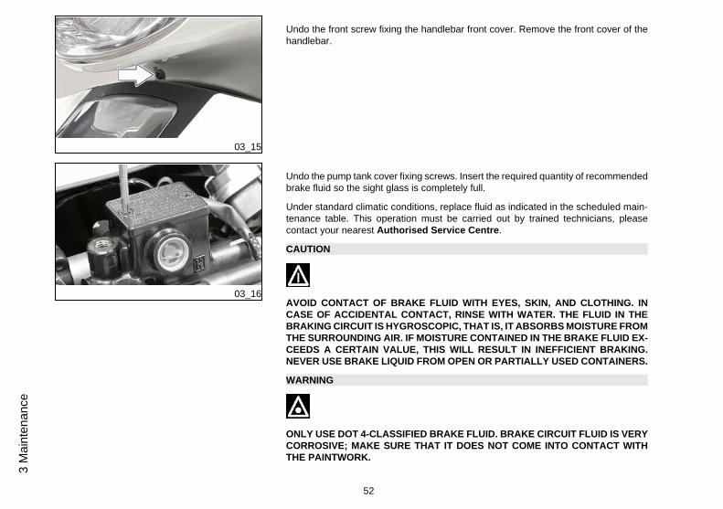
03_15
Undo the front screw fixing the handlebar front cover. Remove the front cover of thehandlebar.
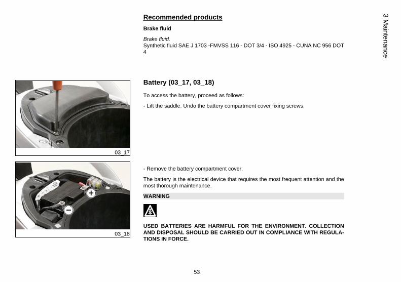
03_16
Undo the pump tank cover fixing screws. Insert the required quantity of recommendedbrake fluid so the sight glass is completely full.
Under standard climatic conditions, replace fluid as indicated in the scheduled main-tenance table. This operation must be carried out by trained technicians, pleasecontact your nearest Authorised Service Centre.
CAUTION
AVOID CONTACT OF BRAKE FLUID WITH EYES, SKIN, AND CLOTHING. INCASE OF ACCIDENTAL CONTACT, RINSE WITH WATER. THE FLUID IN THEBRAKING CIRCUIT IS HYGROSCOPIC, THAT IS, IT ABSORBS MOISTURE FROMTHE SURROUNDING AIR. IF MOISTURE CONTAINED IN THE BRAKE FLUID EX-CEEDS A CERTAIN VALUE, THIS WILL RESULT IN INEFFICIENT BRAKING.NEVER USE BRAKE LIQUID FROM OPEN OR PARTIALLY USED CONTAINERS.
WARNING
ONLY USE DOT 4-CLASSIFIED BRAKE FLUID. BRAKE CIRCUIT FLUID IS VERYCORROSIVE; MAKE SURE THAT IT DOES NOT COME INTO CONTACT WITHTHE PAINTWORK.
52
3 M
aint
enan
ce
Recommended productsBrake fluid
Brake fluid.Synthetic fluid SAE J 1703 -FMVSS 116 - DOT 3/4 - ISO 4925 - CUNA NC 956 DOT4
03_17
Battery (03_17, 03_18)
To access the battery, proceed as follows:
- Lift the saddle. Undo the battery compartment cover fixing screws.
03_18
- Remove the battery compartment cover.
The battery is the electrical device that requires the most frequent attention and themost thorough maintenance.
WARNING
USED BATTERIES ARE HARMFUL FOR THE ENVIRONMENT. COLLECTIONAND DISPOSAL SHOULD BE CARRIED OUT IN COMPLIANCE WITH REGULA-TIONS IN FORCE.
53
3 Maintenance

CAUTION
ELECTROLYTE CONTAINS SULPHURIC ACID: AVOID CONTACT WITH EYES,SKIN AND CLOTHES. IN CASE OF ACCIDENTAL CONTACT, RINSE WITH ABUN-DANT WATER AND CONSULT A DOCTOR.
CAUTION
IN ORDER TO AVOID DAMAGING THE ELECTRIC SYSTEM, NEVER DISCON-NECT THE WIRING WHILE THE ENGINE IS RUNNING.
03_19
Use of a new battery (03_19, 03_20, 03_21, 03_22)
To remove the empty battery, proceed as follows:
Place the scooter on its centre stand and lift the saddle. Remove the battery com-partment cover and undo the negative pole screw «-».
54
3 M
aint
enan
ce

03_20
Undo the positive pole screw «+».
03_21
Remove the battery from its housing. Place the new battery and proceed in reverseorder of the removal.
CAUTION
IT IS IMPORTANT TO OBSERVE THE INDICATED CONNECTION SEQUENCE OFTHE CABLES AT THE BATTERY TO AVOID SHORT-CIRCUITS. WHEN FITTINGTHE NEW BATTERY, FIRST CONNECT THE POSITIVE CABLE «+» AND THENTHE NEGATIVE CABLE «-».
03_22
Ensure that the terminals are connected correctly and check voltage.
CAUTION
DO NOT REVERSE THE POLARITY: RISK OF SHORT CIRCUIT AND DAMAGETO THE ELECTRICAL SYSTEM.
55
3 Maintenance
WARNING
USED BATTERIES ARE HARMFUL FOR THE ENVIRONMENT. COLLECTIONAND DISPOSAL SHOULD BE CARRIED OUT IN COMPLIANCE WITH REGULA-TIONS IN FORCE.
CharacteristicBattery
Sealed, 12 V / 6 Ah
03_23
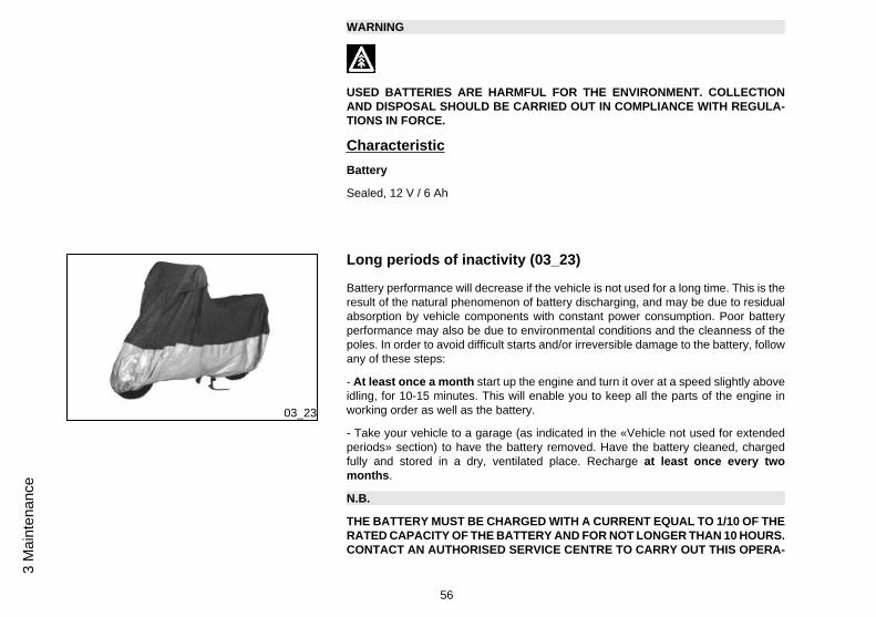
Long periods of inactivity (03_23)
Battery performance will decrease if the vehicle is not used for a long time. This is theresult of the natural phenomenon of battery discharging, and may be due to residualabsorption by vehicle components with constant power consumption. Poor batteryperformance may also be due to environmental conditions and the cleanness of thepoles. In order to avoid difficult starts and/or irreversible damage to the battery, followany of these steps:
- At least once a month start up the engine and turn it over at a speed slightly aboveidling, for 10-15 minutes. This will enable you to keep all the parts of the engine inworking order as well as the battery.
- Take your vehicle to a garage (as indicated in the «Vehicle not used for extendedperiods» section) to have the battery removed. Have the battery cleaned, chargedfully and stored in a dry, ventilated place. Recharge at least once every twomonths.
N.B.
THE BATTERY MUST BE CHARGED WITH A CURRENT EQUAL TO 1/10 OF THERATED CAPACITY OF THE BATTERY AND FOR NOT LONGER THAN 10 HOURS.CONTACT AN AUTHORISED SERVICE CENTRE TO CARRY OUT THIS OPERA-
56
3 M
aint
enan
ce

TION SAFELY. WHEN REFITTING THE BATTERY MAKE SURE THE LEADS ARECORRECTLY CONNECTED TO THE TERMINALS.
WARNING
DO NOT DISCONNECT THE BATTERY CABLES WITH THE ENGINE RUNNING,THIS CAN CAUSE IRREPARABLE DAMAGE TO THE VEHICLE'S ELECTRONICCONTROL UNIT.
WARNING
USED BATTERIES ARE HARMFUL FOR THE ENVIRONMENT. COLLECTIONAND DISPOSAL SHOULD BE CARRIED OUT IN COMPLIANCE WITH REGULA-TIONS IN FORCE.
03_24
Fuses (03_24, 03_25, 03_26, 03_27, 03_28)
MAIN FUSE
The electrical system is protected by a 20A main fuse «1» located near the battery.To reach it, the battery compartment cover must be removed as indicated in the «Bat-tery» section.
In the same position are also two 10A «7» and 25A «8» fuses for the protection of theABS control unit.
57
3 Maintenance
MAIN FUSES TABLEFuse No. 1 Threshold of operation: 20A
Protected circuits:rechargecircuit, general vehicle.
Fuse No. 7 Threshold of operation: 10A
Protected circuits: battery-powered: ABS Control unit.
Fuse No. 8 Threshold of operation: 25A
Protected circuits: battery-powered: ABS Control unit.
03_25
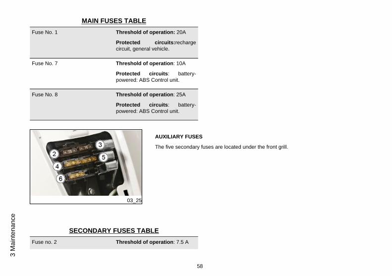
AUXILIARY FUSES
The five secondary fuses are located under the front grill.
SECONDARY FUSES TABLEFuse no. 2 Threshold of operation: 7.5 A
58
3 M
aint
enan
ce
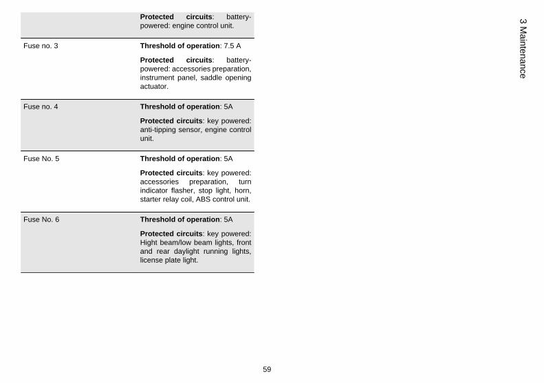
Protected circuits: battery-powered: engine control unit.
Fuse no. 3 Threshold of operation: 7.5 A
Protected circuits: battery-powered: accessories preparation,instrument panel, saddle openingactuator.
Fuse no. 4 Threshold of operation: 5A
Protected circuits: key powered:anti-tipping sensor, engine controlunit.
Fuse No. 5 Threshold of operation: 5A
Protected circuits: key powered:accessories preparation, turnindicator flasher, stop light, horn,starter relay coil, ABS control unit.
Fuse No. 6 Threshold of operation: 5A
Protected circuits: key powered:Hight beam/low beam lights, frontand rear daylight running lights,license plate light.
59
3 Maintenance

03_26
To access the auxiliary fuses proceed as follows:
Remove the Piaggio clip-on badge using a flat screwdriver.
03_27
Unscrew the screw fixing the grille to the chassis.
03_28
Remove the grille by slightly pulling it upwards and releasing the seat tongues.
CAUTION
BEFORE REPLACING THE FUSE IT IS NECESSARY TO FIND AND SOLVE THEFAILURE THAT CAUSED IT TO BLOW.
DO NOT REPLACE THE FUSE WITH ANY ALTERNATIVE FORM OF CONDUC-TOR.
60
3 M
aint
enan
ce
CAUTION
IN ORDER TO AVOID DAMAGING THE ELECTRIC SYSTEM, NEVER DISCON-NECT THE WIRING WHILE THE ENGINE IS RUNNING. DO NOT TIP THE VEHICLETOO MUCH IN ORDER TO AVOID DANGEROUS LEAKAGE OF THE BATTERYELECTROLYTE.
CAUTION
MODIFICATIONS OR REPAIRS TO THE ELECTRICAL SYSTEM, PERFORMEDINCORRECTLY OR WITHOUT STRICT ATTENTION TO THE TECHNICAL SPEC-IFICATIONS OF THE SYSTEM CAN CAUSE MALFUNCTIONING AND RISK OFFIRE.
CAUTION
PROCEED WITH CAUTION.DO NOT DAMAGE THE TABS AND/OR THEIR CORRESPONDING SLOTS. HAN-DLE THE PLASTIC AND PAINTED COMPONENTS WITH CARE, DO NOTSCRATCH OR IMPAIR THEM.
61
3 Maintenance
03_29
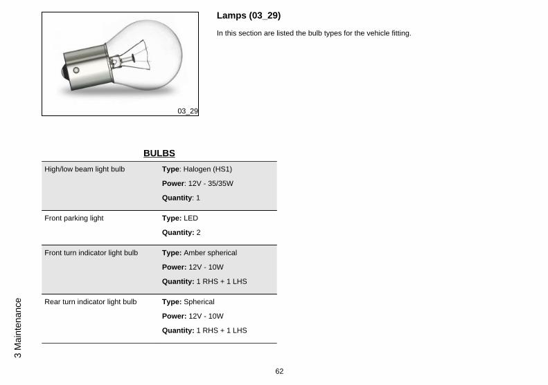
Lamps (03_29)
In this section are listed the bulb types for the vehicle fitting.
BULBSHigh/low beam light bulb Type: Halogen (HS1)
Power: 12V - 35/35W
Quantity: 1
Front parking light Type: LED
Quantity: 2
Front turn indicator light bulb Type: Amber spherical
Power: 12V - 10W
Quantity: 1 RHS + 1 LHS
Rear turn indicator light bulb Type: Spherical
Power: 12V - 10W
Quantity: 1 RHS + 1 LHS
62
3 M
aint
enan
ce
Rear tail light bulb Type: All glass
Power: 12V 5W
Quantity: 2
Stop light bulb Type: Spherical
Power: 12V 10W
Quantity: 1
Licence plate light bulb Type: Capless
Power: 12V - 5W
Quantity: 1
03_30
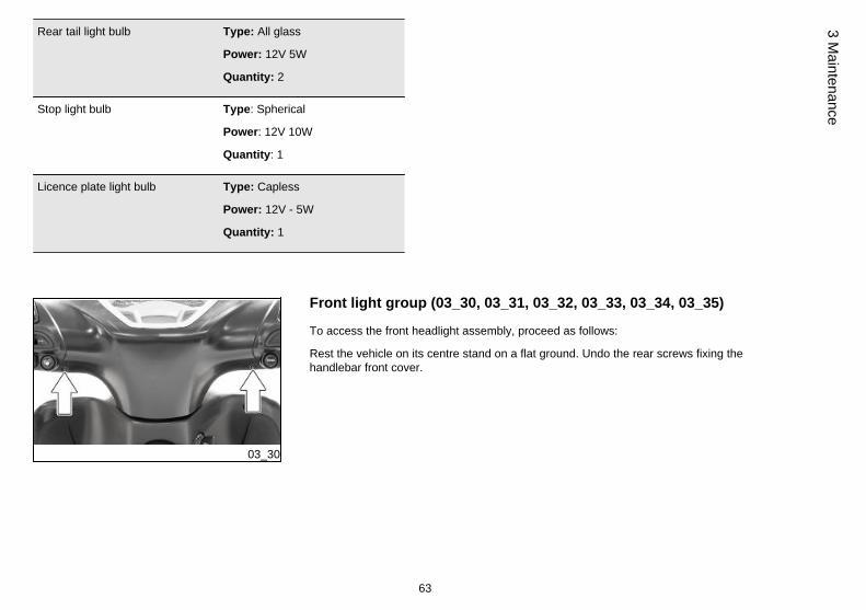
Front light group (03_30, 03_31, 03_32, 03_33, 03_34, 03_35)
To access the front headlight assembly, proceed as follows:
Rest the vehicle on its centre stand on a flat ground. Undo the rear screws fixing thehandlebar front cover.
63
3 Maintenance

03_31
Undo the front screw fixing the handlebar front cover. Remove the front cover of thehandlebar.
03_32
Disconnect the connector from the low beam/high beam lights bulb.
CAUTION
DO NOT PULL THE ELECTRICAL CABLES WHEN DISCONNECTING THE ELEC-TRICAL CONNECTOR.
03_33
Remove the protective cap.
64
3 M
aint
enan
ce

03_34
Turn the fixing ring nut of the low beam/high beam lights bulb anticlockwise and re-move it.
03_35
Remove the low beam/high beam lights bulb and replace it with a new bulb. Followthe process in reverse order to refit.
N.B.
IF MISTING IS NOTICED ON THE INSIDE OF THE HEADLAMP GLASS, THISDOES NOT INDICATE AN ABNORMALITY AND IS RELATED TO HUMIDITY AND/OR LOW TEMPERATURES.
IT WILL DISAPPEAR QUICKLY WHEN THE HEADLIGHT IS TURNED ON.
IF HOWEVER THERE ARE DROPS OF WATER, IT MIGHT MEAN SEEPAGE ANDYOU SHOULD SEE AN AUTHORISED ASSISTANCE CENTRE.
CAUTION
DO NOT REST OR TRANSPORT OBJECTS AND/OR CLOTHING ON TOP OF THEFRONT LIGHT ASSEMBLY WITH THE LIGHT ON OR JUST TURNED OFF. FAIL-URE TO OBSERVE THIS PRECAUTION MAY CAUSE THE GLASS TO OVERHEATAND CONSEQUENTLY MELT.
65
3 Maintenance

FRONT HEADLIGHT ASSEMBLY BULBHigh/low beam light bulb Type: Halogen (HS1)
Power: 12V - 35/35W
Quantity: 1
Front parking light Type: LED
Quantity: 2
03_36
03_37
Head light adjustment (03_36, 03_37)
Proceed as follows:
1. Position the vehicle in running order and with the tyres inflated to the prescribedpressure, onto a flat surface 10 m away from a half-lit white screen; ensure that thelongitudinal axis of the vehicle is perpendicular to the screen;
2. Turn on the headlight and check that the boundary of the light beam projected ontothe screen is not higher than 9/10 or lower than 7/10 of the distance between the centreof the headlight and the ground;
3. If this is not the case, adjust the right headlight by operating the screw indicated.
N.B.
THE ABOVE PROCEDURE COMPLIES WITH THE EUROPEAN STANDARDS RE-GARDING MAXIMUM AND MINIMUM HEIGHT OF LIGHT BEAMS. REFER TO THESTATUTORY REGULATIONS IN FORCE IN EVERY COUNTRY WHERE THE VE-HICLE IS USED.
66
3 M
aint
enan
ce

Front direction indicators
In the event of malfunction, we recommend contacting an Authorised Service Cen-tre for replacement.
FRONT TURN INDICATORS BULBSFront turn indicator light bulb Type: Amber spherical
Power: 12V - 10W
Quantity: 1 RHS + 1 LHS
03_38
Rear optical unit (03_38, 03_39, 03_40, 03_41, 03_42, 03_43,03_44, 03_45, 03_46, 03_47, 03_48)
To replace the taillight bulbs, proceed as follow:
Remove the luggage carrier cover.
67
3 Maintenance

03_39
Unscrew the upper fixing screw of the rear light unit.
03_40
Use a screwdriver, remove the chromed covers from both sides of the vehicle. Becareful not to damage them.
CAUTION
PROCEED WITH CAUTION.DO NOT DAMAGE THE TABS AND/OR THEIR CORRESPONDING SLOTS. HAN-DLE THE PLASTIC AND PAINTED COMPONENTS WITH CARE, DO NOTSCRATCH OR IMPAIR THEM.
03_41
Unscrew the rear light unit side fastening screw from both sides of the vehicle.
68
3 M
aint
enan
ce

03_42
Remove the rear light unit from its seat.
03_43
Turn the turn indicator lights bulb holder anticlockwise and remove it from its seat.
03_44
Lightly press the bulb, turn it anticlockwise and remove it from the bulb holder. To refit,proceed in reverse order.
69
3 Maintenance
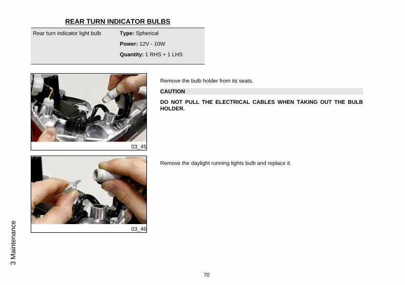
REAR TURN INDICATOR BULBSRear turn indicator light bulb Type: Spherical
Power: 12V - 10W
Quantity: 1 RHS + 1 LHS
03_45
Remove the bulb holder from its seats.
CAUTION
DO NOT PULL THE ELECTRICAL CABLES WHEN TAKING OUT THE BULBHOLDER.
03_46
Remove the daylight running lights bulb and replace it.
70
3 M
aint
enan
ce
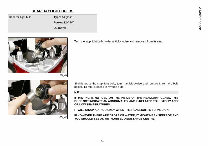
REAR DAYLIGHT BULBSRear tail light bulb Type: All glass
Power: 12V 5W
Quantity: 2
03_47
Turn the stop light bulb holder anticlockwise and remove it from its seat.
03_48
Slightly press the stop light bulb, turn it anticlockwise and remove it from the bulbholder. To refit, proceed in reverse order.
N.B.
IF MISTING IS NOTICED ON THE INSIDE OF THE HEADLAMP GLASS, THISDOES NOT INDICATE AN ABNORMALITY AND IS RELATED TO HUMIDITY AND/OR LOW TEMPERATURES.
IT WILL DISAPPEAR QUICKLY WHEN THE HEADLIGHT IS TURNED ON.
IF HOWEVER THERE ARE DROPS OF WATER, IT MIGHT MEAN SEEPAGE ANDYOU SHOULD SEE AN AUTHORISED ASSISTANCE CENTRE.
71
3 Maintenance
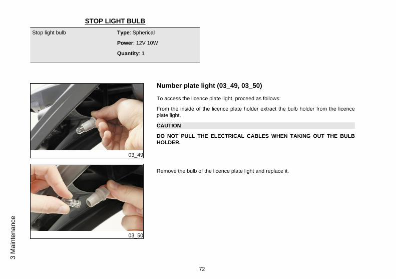
STOP LIGHT BULBStop light bulb Type: Spherical
Power: 12V 10W
Quantity: 1
03_49
Number plate light (03_49, 03_50)
To access the licence plate light, proceed as follows:
From the inside of the licence plate holder extract the bulb holder from the licenceplate light.
CAUTION
DO NOT PULL THE ELECTRICAL CABLES WHEN TAKING OUT THE BULBHOLDER.
03_50
Remove the bulb of the licence plate light and replace it.
72
3 M
aint
enan
ce

LICENCE PLATE LIGHT BULBLicence plate light bulb Type: Capless
Power: 12V - 5W
Quantity: 1
03_51
Rear-view mirrors (03_51, 03_52)
The mirrors can be set to the desired position by adjusting the mirror frame.
03_52
To remove the rear view mirror, lift the rubber protection «A», unscrew the nut «B»slightly to unlock the stem. Slide off the complete mirror.
CAUTION
DO NOT ADJUST THE MIRRORS WHILE RIDING. THIS COULD CAUSE YOU TOLOOSE CONTROL OF THE VEHICLE.
73
3 Maintenance

03_53
Front disc brake (03_53)
The brake disc and pad wear is automatically compensated, therefore it has no effecton the functioning of the front and rear brakes. For this reason it is not necessary toadjust the brakes. An excessively elastic brake lever stroke may indicate the presenceof air in the braking circuit or an irregular brake operation. In this case, particularlyconsidering the importance of the brakes in terms of safety, it is strongly recommendedthat you take the vehicle to an Authorised Service Centre as soon as possible forthe appropriate checks.
WARNING
CHECK BRAKE PADS FOR WEAR ON A REGULAR BASIS (AS INDICATED INTHE SCHEDULE MAINTENANCE TABLES). IF THE THICKNESS OF ONE ORBOTH PADS IS IN THE REGION OF 1.5 MM, BOTH PADS MUST BE CHANGED.IT IS RECOMMENDED TO CARRY OUT THIS OPERATION AT AN AUTHORISEDSERVICE CENTRE AS SOON AS POSSIBLE.
AFTER FITTING NEW BRAKE PADS DO NOT USE THE VEHICLE UNTIL YOUHAVE ACTIVATED THE BRAKE LEVER REPEATEDLY TO POSITION THE PADSAND RESTORE THE LEVER STROKE TO ITS CORRECT POSITION.
CAUTION
BRAKING SHOULD BEGIN AFTER ABOUT 1/3 OF THE BRAKE LEVER STROKE.
74
3 M
aint
enan
ce
03_54
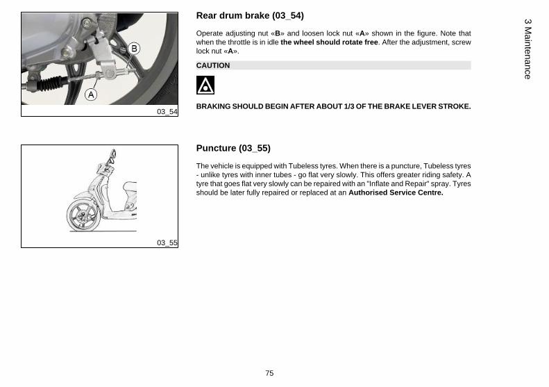
Rear drum brake (03_54)
Operate adjusting nut «B» and loosen lock nut «A» shown in the figure. Note thatwhen the throttle is in idle the wheel should rotate free. After the adjustment, screwlock nut «A».
CAUTION
BRAKING SHOULD BEGIN AFTER ABOUT 1/3 OF THE BRAKE LEVER STROKE.
03_55
Puncture (03_55)
The vehicle is equipped with Tubeless tyres. When there is a puncture, Tubeless tyres- unlike tyres with inner tubes - go flat very slowly. This offers greater riding safety. Atyre that goes flat very slowly can be repaired with an "Inflate and Repair" spray. Tyresshould be later fully repaired or replaced at an Authorised Service Centre.
75
3 Maintenance

03_56
Inactivity of the vehicle (03_56)
The following operations are recommended:
1 - General cleaning of the vehicle.
2 - With the engine off and the piston at bottom dead centre position, remove the sparkplug and pour 1-2 cm³ of motor oil through its hole. Operate the starter motor 3-4 timesletting the engine perform a few revolutions, then remount the spark plug.
3 - Drain up all the vehicle's fuel; spread antirust grease on the uncoated metal parts;keep the wheels lifted above the ground.
4 - For the battery, follow the procedures described in the «Battery» section.
5 - Replace engine oil.
Recommended productsEngine oil
Synthetic-based lubricant for four stroke engines.SAE 10W-40, JASO MA, MA2 - API SL - ACEA A3
Cleaning the vehicle (03_57)
Use a low pressure jet of water to soften the caked dirt and mud deposited on thepainted surfaces. Once softened, sponge off mud and dirt using a car body spongesoaked in a car body shampoo and water solution (2-4% of car shampoo in water).Then rinse with abundant water, and dry with a chamois cloth. For the engine exterior,use petrol, a brush and clean cloths. Petrol can damage paintwork. Remember thatany polishing with silicone wax must always be preceded by washing.
76
3 M
aint
enan
ce
WARNING
To avoid the appearance of oxidations, wash the vehicle every time it is used incertain areas or in special conditions of:
· Environmental / seasonal conditions: use of salt, de-icer chemical products onthe road in winter.
· Air pollution: city and/or industrial areas.
· Salinity and humidity of the atmosphere: marine areas, hot and wet weather.
WARNING
. Prevent deposits from remaining on the bodywork, industrial and pollutantresidual dust, tar spots, dead insects, bird droppings, etc.
· Do not park the vehicle under the trees. In some seasons, in fact, residues,resins, fruits or leaves may fall from the trees, containing chemicals that areharmful to the paintwork.
CAUTION
DETERGENTS POLLUTE WATER. THEREFORE THE VEHICLE SHOULD BEWASHED IN AN AREA EQUIPPED FOR THE COLLECTION AND PURIFICATIONOF THE LIQUIDS USED.
77
3 Maintenance

WARNING
NEVER WASH THE VEHICLE UNDER DIRECT SUNLIGHT, ESPECIALLY IN SUM-MER WHEN THE BODYWORK IS STILL HOT, AS THE CAR SHAMPOO MAY DRYBEFORE BEING RINSED OFF, AND COULD DAMAGE THE PAINTWORK. NEVERUSE RAGS SOAKED IN PETROL OR DIESEL OIL TO CLEAN THE PAINTED ORPLASTIC SURFACES, IN ORDER TO PREVENT THEM LOSING THEIR SHINEAND MECHANICAL CHARACTERISTICS.
WARNING
WHEN WASHING THE ENGINE WITH A HIGH-PRESSURE WATER JET:
• ONLY USE FAN SPRAY JETS.• DO NOT PLACE THE WATER JET NOZZLE CLOSER THAN 60 CM.• DO NOT USE WATER AT TEMPERATURES OVER 40ºC.• DO NOT DIRECT THE JET AT THE THROTTLE BODY, THE ELECTRIC CABLES,THE COOLING SLITS IN THE TRANSMISSION COVER AND THE SPIRAL COVER,THE FUEL TANK CAP.
03_57
WARNING
WHEN CLEANING THE VEHICLE WITH A PRESSURE CLEANER, DO NOT DI-RECT THE WATER JET ON ANY PART OF THE ENGINE OR BODYWORK FORPROLONGED PERIODS.
78
3 M
aint
enan
ce

Troubleshooting
START-UP PROBLEMSNo fuel in tank Refuel
Injection system fault Contact an Authorised ServiceCentre.
Insufficient battery charge Recharge the battery
Fuel pump fault Contact an Authorised ServiceCentre.
IGNITION PROBLEMSNo spark from spark plug. Due tothe presence of high voltage, thischeck should only be carried out byan expert
Check that the electrodes areproperly adjusted (0.7÷ 0.8 mm).Check that the electrodes areclean. Check the spark pluginsulator: replace the spark plug ifthe insulator is cracked or broken.If the spark plug is in goodconditions, contact an AuthorisedService Centre.
Faulty ignition / injection controlunit.
Contact an Authorised ServiceCentre.
79
3 Maintenance

LACK OF COMPRESSIONSpark plug adapter "worn", valveclearance not adequate; wornpiston gas rings
Contact an Authorised ServiceCentre.
HIGH CONSUMPTION AND LOW PERFORMANCEAir filter blocked or dirty Contact an Authorised Service
Centre.
INEFFICIENT BRAKINGOil on drum or disc. Worn Pads/Shoes
Contact an Authorised ServiceCentre
incorrect rear brake adjustment Adjust
INEFFICIENT SUSPENSIONInefficient shock absorbers, oilleakage, deteriorated end of strokebuffers.
Contact an Authorised ServiceCentre
80
3 M
aint
enan
ce
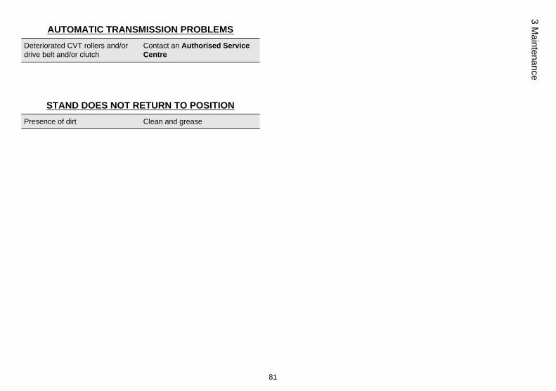
AUTOMATIC TRANSMISSION PROBLEMSDeteriorated CVT rollers and/ordrive belt and/or clutch
Contact an Authorised ServiceCentre
STAND DOES NOT RETURN TO POSITIONPresence of dirt Clean and grease
81
3 Maintenance

82
3 M
aint
enan
ce

Liberty ABS
Chap. 04Technical data
83

Data (04_01)
04_01
84
4 Te
chni
cal d
ata
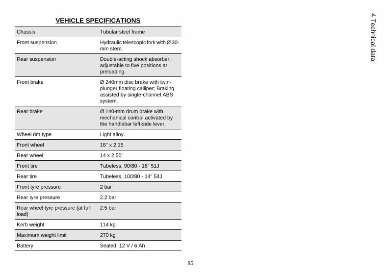
VEHICLE SPECIFICATIONSChassis Tubular steel frame
Front suspension Hydraulic telescopic fork with Ø 30-mm stem.
Rear suspension Double-acting shock absorber,adjustable to five positions atpreloading.
Front brake Ø 240mm disc brake with twin-plunger floating calliper; Brakingassisted by single-channel ABSsystem.
Rear brake Ø 140-mm drum brake withmechanical control activated bythe handlebar left-side lever.
Wheel rim type Light alloy.
Front wheel 16'' x 2.15
Rear wheel 14 x 2.50''
Front tire Tubeless, 90/80 - 16" 51J
Rear tire Tubeless, 100/80 - 14" 54J
Front tyre pressure 2 bar
Rear tyre pressure 2.2 bar
Rear wheel tyre pressure (at fullload)
2.5 bar
Kerb weight 114 kg
Maximum weight limit 270 kg
Battery Sealed, 12 V / 6 Ah
85
4 Technical data
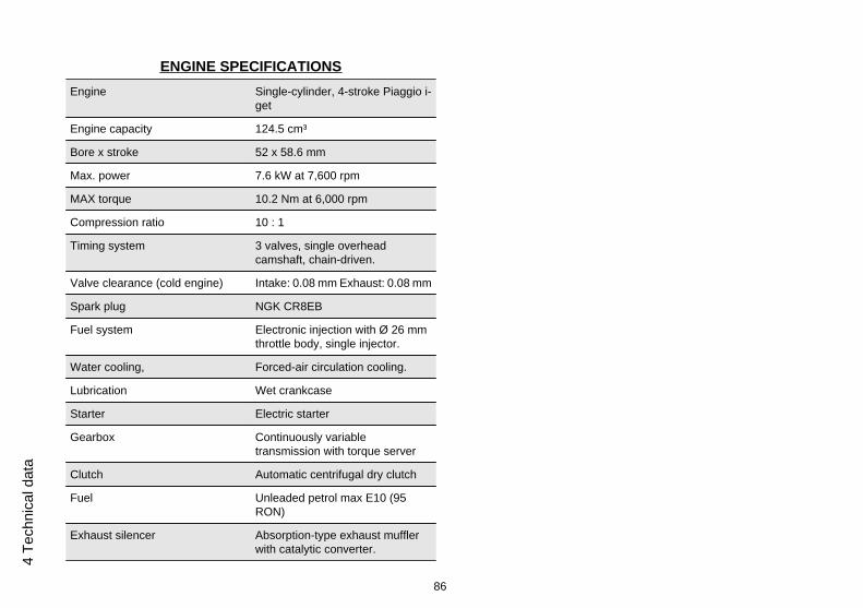
ENGINE SPECIFICATIONSEngine Single-cylinder, 4-stroke Piaggio i-
get
Engine capacity 124.5 cm³
Bore x stroke 52 x 58.6 mm
Max. power 7.6 kW at 7,600 rpm
MAX torque 10.2 Nm at 6,000 rpm
Compression ratio 10 : 1
Timing system 3 valves, single overheadcamshaft, chain-driven.
Valve clearance (cold engine) Intake: 0.08 mm Exhaust: 0.08 mm
Spark plug NGK CR8EB
Fuel system Electronic injection with Ø 26 mmthrottle body, single injector.
Water cooling, Forced-air circulation cooling.
Lubrication Wet crankcase
Starter Electric starter
Gearbox Continuously variabletransmission with torque server
Clutch Automatic centrifugal dry clutch
Fuel Unleaded petrol max E10 (95RON)
Exhaust silencer Absorption-type exhaust mufflerwith catalytic converter.
86
4 Te
chni
cal d
ata

Emissions compliance EURO 2
CAPACITYEngine oil quantity 1,340 cm³ (of which 120 cm³ in the
filtering cartridge)
Hub oil quantity 325 cm³
Fuel tank capacity 6 ± 0.5 litres (1 l of which is reserve)
87
4 Technical data

88
4 Te
chni
cal d
ata

Liberty ABS
Chap. 05Spare parts and
accessories
89

05_01
Warnings (05_01)
WARNING
IT IS RECOMMENDED THAT "ORIGINAL PIAGGIO SPARE PARTS" BE USED,AS THESE ARE THE ONLY ONES OFFERING YOU THE SAME QUALITY AS-SURANCE AS THOSE INITIALLY FITTED ON THE VEHICLE.
IT SHOULD BE REMEMBERED THAT USING NON-ORIGINAL SPARE PARTSCAUSES YOUR WARRANTY RIGHTS TO EXPIRE.
WARNING
PIAGGIO MARKETS ITS OWN LINE OF ACCESSORIES THAT ARE RECOG-NISED AND GUARANTEED FOR USE. IT IS THEREFORE ESSENTIAL TO CON-TACT AN AUTHORISED DEALER OR SERVICE CENTRE IN ORDER TO CHOOSEAND FIT ACCESSORIES CORRECTLY. THE USE OF NON-ORIGINAL ACCES-SORIES MAY AFFECT THE STABILITY AND OPERATION OF YOUR VEHICLEAND REDUCE SAFETY LEVELS WITH POTENTIAL RISKS FOR THE RIDER.
90
5 Sp
are
parts
and
acc
esso
ries
Liberty ABS
Chap. 06Scheduled
maintenance
91
06_01
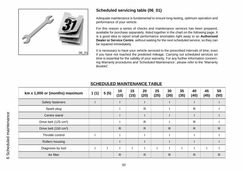
Scheduled servicing table (06_01)
Adequate maintenance is fundamental to ensure long-lasting, optimum operation andperformance of your vehicle.
For this reason a series of checks and maintenance services has been prepared,available for purchase separately, listed together in the chart on the following page. Itis a good idea to report small performance anomalies right away to an AuthorisedDealer or Service Centre, without waiting for the next scheduled service, so they canbe repaired immediately.
It is necessary to have your vehicle serviced to the prescribed intervals of time, evenif you have not reached the predicted mileage. Carrying out scheduled services ontime is essential for the validity of your warranty. For any further information concern-ing Warranty procedures and 'Scheduled Maintenance', please refer to the 'WarrantyBooklet'.
SCHEDULED MAINTENANCE TABLE
km x 1,000 or (months) maximum 1 (1) 5 (5) 10(10)
15(15)
20(20)
25(25)
30(30)
35(35)
40(40)
45(45)
50(50)
Safety fasteners I I I I I I
Spark plug I R I R I
Centre stand I I I I I
Drive belt (125 cm³) I R I R I
Drive belt (150 cm³) R R R R R
Throttle control I I I I I I
Rollers housing I I I I I
Diagnosis by tool I I I I I I I I I I I
Air filter R R R R R
92
6 Sc
hedu
led
mai
nten
ance
km x 1,000 or (months) maximum 1 (1) 5 (5) 10(10)
15(15)
20(20)
25(25)
30(30)
35(35)
40(40)
45(45)
50(50)
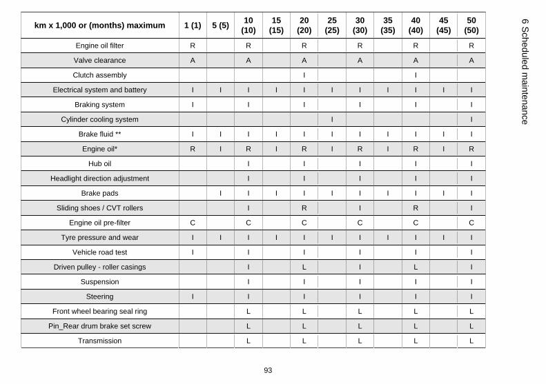
Engine oil filter R R R R R R
Valve clearance A A A A A A
Clutch assembly I I
Electrical system and battery I I I I I I I I I I I
Braking system I I I I I I
Cylinder cooling system I I
Brake fluid ** I I I I I I I I I I I
Engine oil* R I R I R I R I R I R
Hub oil I I I I I
Headlight direction adjustment I I I I I
Brake pads I I I I I I I I I I
Sliding shoes / CVT rollers I R I R I
Engine oil pre-filter C C C C C C
Tyre pressure and wear I I I I I I I I I I I
Vehicle road test I I I I I I
Driven pulley - roller casings I L I L I
Suspension I I I I I
Steering I I I I I I
Front wheel bearing seal ring L L L L L
Pin_Rear drum brake set screw L L L L L
Transmission L L L L L
93
6 Scheduled maintenance

km x 1,000 or (months) maximum 1 (1) 5 (5) 10(10)
15(15)
20(20)
25(25)
30(30)
35(35)
40(40)
45(45)
50(50)
Labour time (minutes) 50 30 140 30 140 30 140 30 140 30 140
I: CHECK AND CLEAN, ADJUST, LUBRICATE OR REPLACE, IF NECESSARY C: CLEAN; R: REPLACE; A: ADJUST; L: LUBRICATE
* Check level every 2,500 km
** Replace every 2 years
N.B.
AT EACH SCHEDULED MAINTENANCE MUST BE VERIFIED WITH THE DIAG-NOSTIC TOOL IF THERE ARE ERRORS AND THE IF THE PARAMETERS ARECORRECT.
ENSURE THAT THE VEHICLE CALIBRATION IS UP TO DATE AFTER UPDATINGTHE DIAGNOSTIC TOOL.
CAUTION
AFTER THE PROVIDED MAINTENANCE PROGRAM IS INDICATED TO PRO-CEED WITH THE MAINTENANCE OF THE VEHICLE STARTING FROM THESERVICE OF 5,000 km (3,106 mi) OR 5 MONTHS.
Table of recommended products
RECOMMENDED PRODUCTS TABLEProduct Description Specifications
Lubricant for gearboxes and transmissions Lubricant for gearboxes and transmissions. SAE 80W/90, APIGL4
94
6 Sc
hedu
led
mai
nten
ance

Product Description Specifications
Brake fluid Brake fluid. Synthetic fluid SAE J 1703 -FMVSS 116 - DOT3/4 - ISO 4925 - CUNA NC 956 DOT 4
Engine oil Synthetic-based lubricant for four strokeengines.
SAE 10W-40, JASO MA, MA2 - API SL - ACEAA3
Oil for air filter sponge Special product for the treatment of foamfilters.
-
Lubricant Lithium and medium fibre yellow browncoloured grease suitable for various uses.
ISO L-X-BCHA 3 - DIN 51 825 K3K -20
Lubricant Water repellent stringy calcium spray grease. R.I.D./A.D.R. 2 10°b) 2 R.I.Na. 2.42 - I.A.T.A.2 - I.M.D.G. class 2 UN 1950 Pag. 9022 EM25-89
UNIT OF MEASURE - CONVERSION - ENGLISH SYSTEMTO INTERNATIONAL SYSTEM (IS).
1 Inch (in) 25.4 Millimetres (mm)
1 Foot (ft) 0.305 Meter (m)
1 Mile (mi) 1.609 Kilometre (km)
1 US Gallon (US gal) 3.785 Litre (l)
1 Pound (lb) 0.454 Kilogram (kg)
1 Cubic inch (in³) 16.4 Cubic centimetres (cm³)
1 Foot pound (lb ft) 1,356 Newton meter (Nm)
1 Miles per hour (mi/h) 1.602 kilometres per hour (Km/h)
1 Pound per square inch (PSI) 0.069 (bar)
95
6 Scheduled maintenance
1 Fahrenheit (°F) 32+(9/5) Celsius (°C)
96
6 Sc
hedu
led
mai
nten
ance

TABLE OF CONTENTS
AABS: 18Air filter: 50
BBattery: 53, 54Brake: 51, 74, 75
CChecks: 28Clock: 11
DDisc brake: 74Display: 12
EEngine oil: 42–44
FFuses: 57
HHorn: 17Hub oil: 44
IIdentification: 24Immobilizer: 20Instrument panel: 9
KKeys: 20
LLight switch: 17
MMaintenance: 41, 91Mirrors: 73
PPuncture: 75
RRecommended products: 94Refuelling: 28
SSaddle: 23Scheduled maintenance: 91Shock absorbers: 31Spark plug: 47Stand: 36Start-up: 18Switch: 16, 17
TTechnical Data: 83Top box: 25Transmission: 37Tyre pressure: 30Tyres: 46
VVehicle: 7, 76
97

The descriptions and images in this publication are given for illustrative purposes only and are not binding. While the basic specifications as described and illustrated in this manual remain unchanged,Piaggio Việt Nam reserves the right, at any time and without being required, to update this publication beforehand, to make any changes to components, parts or accessories, which it considers necessary
to improve the product or which are required for manufacturing or construction reasons.
Not all versions/models shown in this publication are available in all countries. The availability of each model should be checked at the official Piaggio sales network.
"© Copyright 2016 - PIAGGIO VIỆT NAM. All rights reserved. Reproduction of this publication in whole or in part is prohibited."
PIAGGIO VIỆT NAM- After Sales
LOT M - BINH XUYEN INDUSTRIAL ZONE - VINCH PHUC - VIET NAM
CUSTOMER SERVICE CENTRE
Please contact us:
Hot line: 1800 5555 85
Email:[email protected]
Website:www.piaggio.com.vn