libengine: a c++ object-oriented platform for intake and...
TRANSCRIPT

libEngine: a C++ object-oriented platform forintake and exhaust system simulation
Federico Piscaglia
Dipartimento di Energia, POLITECNICO DI MILANO
Acknowledgements
2 /47 Federico Piscaglia - Dip. di Energia, Politecnico di Milano
Ph.D. student Andrea Montorfano , Politecnico di Milano
Prof. Hrvoje Jasak - Wikki Ltd., University of Zagreb
Prof. Giancarlo Ferrari Politecnico di MilanoProf. Angelo Onorati Politecnico di MilanoDr. Tommaso Lucchini Politecnico di MilanoDr. Gianluca D’Errico Politecnico di MilanoDr. Gianluca Montenegro Politecnico di MilanoMr. Daniele Ettorre Politecnico di Milano
Prof. Chris J. Rutland , Prof. David E. Foster - ERC, University of Wisconsin-Madison (USA)
Mr. Luciano Spaggiari , MV Agusta SpA (Italy)

Summary of topics
3 /47 Federico Piscaglia - Dip. di Energia, Politecnico di Milano
The OpenFOAM R© technology: an overview
The libEngine R© project: an overview
Diesel exhaust aftertreatment modeling
numerical methods for flows through porous media
automatic mesh generation of complex geometries
1D-3D coupling
acoustics and silencers
Test cases and applications
Disclaimer: this offering is not approved or endorsed by OpenCFD R©Limited, the producer of the OpenFOAM R© software and owner of the OpenFOAM R© and
OpenCFD R© trade marks.

OpenFOAM R©: an open-source CFD toolbox
4 /47 Federico Piscaglia - Dip. di Energia, Politecnico di Milano
OpenFOAM R© is an open source , freely available CFD Toolbox , licensed under the GNU General PublicLicence, written in highly efficient C++ object-oriented programming . OpenFOAM R© uses the finitevolume approach to solve systems of partial differential equations ascribed on any 3D unstructuredmesh of polyhedral cells . Domain decomposition parallelism is integrated at a low lev el so that theimplementation of parallel solvers can be performed without the need for any “parallel-specific” coding.
Objective : open source implementation of existing knowledge and an object-oriented platform for easyand collaborative future development
1. Completely open software platform using object-oriented design
2. Extensive modelling capabilities in library form: component re-use
3. Collaborative and project-driven model development
This furthers the research and collaboration by removing proprietary software issues: source codeand algorithmic details available to all

Top-Level Solver Code
5 /47 Federico Piscaglia - Dip. di Energia, Politecnico di Milano
Application Development in OpenFOAM R©
Custom-written top-level solvers are written for each class of physics
Writing top-level code is very similar to manipulating the equations
Ultimate user-coding capabilities: components can be re-used to handle most problems in computa-tional continuum mechanics
Layered Development
Design encourages code re-use : developing shared tools
Classes and functional components developed and tested in isolation
• Vectors, tensors and field algebra
• Mesh handling, refinement, mesh motion, topological changes
• Discretisation, boundary conditions
• Matrices and linear solver technology
• Physics by segment in library form
Library level mesh, pre-, post- and data handling utilities
Model-to-model interaction handled through common interfaces
New components do not disturb existing code: fewer bugs
OpenFOAM R© technology: pre-implemented capabilities
6 /47 Federico Piscaglia - Dip. di Energia, Politecnico di Milano
OpenFOAM R© library:
Finite-volume discretization with polyhedral cell support
Finite-element mesh motion + topological changes
Lagrangian particle tracking algorithm
Thermo-physical models for liquid and gas
Detailed chemistry
OpenFOAM R© applications/solvers:
Compressible flow solvers: RANS, LES, pressure-density based, density based, steady, unsteady
Combustion: premixed or non-premixed combustion models
heatTransfer: solvers for buoyancy-driven or Bousinnesq flows
Incompressible flows: (steady, unsteady, viscid, inviscid, RANS, LES, . . . )
Third OpenFOAM R© Workshop in Milan
7 /47 Federico Piscaglia - Dip. di Energia, Politecnico di Milano
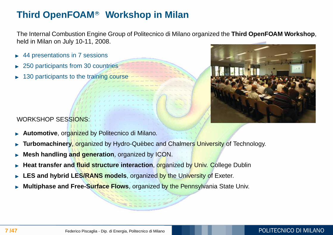
The Internal Combustion Engine Group of Politecnico di Milano organized the Third OpenFOAM Workshop ,held in Milan on July 10-11, 2008.
44 presentations in 7 sessions
250 participants from 30 countries
130 participants to the training course
WORKSHOP SESSIONS:
Automotive , organized by Politecnico di Milano.
Turbomachinery , organized by Hydro-Quebec and Chalmers University of Technology.
Mesh handling and generation , organized by ICON.
Heat transfer and fluid structure interaction , organized by Univ. College Dublin
LES and hybrid LES/RANS models , organized by the University of Exeter.
Multiphase and Free-Surface Flows , organized by the Pennsylvania State Univ.
OpenFOAM R©-related CFD projects
8 /47 Federico Piscaglia - Dip. di Energia, Politecnico di Milano
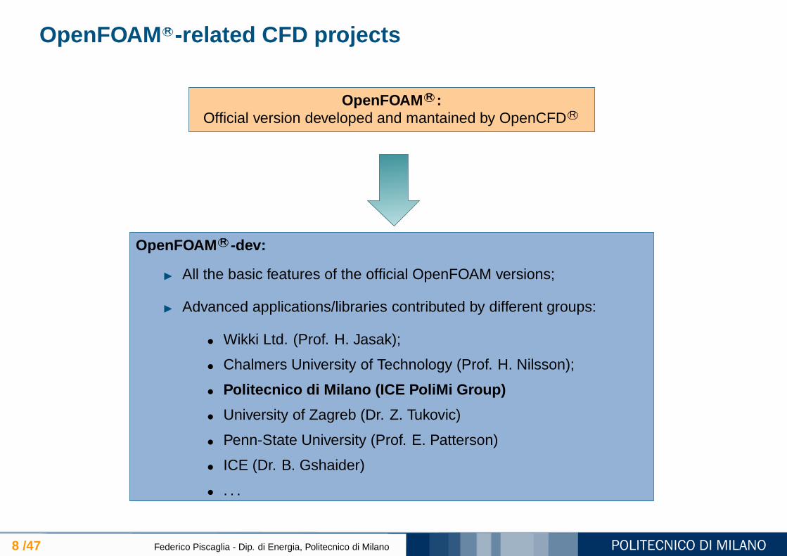
OpenFOAM R©:Official version developed and mantained by OpenCFD R©
OpenFOAM R©-dev:
All the basic features of the official OpenFOAM versions;
Advanced applications/libraries contributed by different groups:
• Wikki Ltd. (Prof. H. Jasak);
• Chalmers University of Technology (Prof. H. Nilsson);
• Politecnico di Milano (ICE PoliMi Group)
• University of Zagreb (Dr. Z. Tukovic)
• Penn-State University (Prof. E. Patterson)
• ICE (Dr. B. Gshaider)
• . . .

libEngine R© for exhaust aftertreatment simulation
9 /47 Federico Piscaglia - Dip. di Energia, Politecnico di Milano
Introduce new data types (classes) appropriate for the problem:
Class : user defined type representing one part of the problem I have to solve (mesh, matrix, field, ...)
Library : definition and implementation of related classes and functions (finite volume library, turbulencemodel library, mesh tools library...)
Applications : collection of object of different classes interacting each others

libEngine R©
10 /47 Federico Piscaglia - Dip. di Energia, Politecnico di Milano
/home/OpenFOAM
libEngine-1.5-dev OpenFOAM-1.5-dev
src
applications
porousJump:
porousFace:
turbulenceModelsPolimi:DPF-specific porous wall class
base class for thin porous surfaces
modified RANS models for laminar-turbulent interaction
solvers:
steady and unsteady solvers with thin
porous surfaces and modified RANS
modelsutilities:
automatic mesh generation, preprocessing, post-processing

DPF modeling: motivation
11 /47 Federico Piscaglia - Dip. di Energia, Politecnico di Milano
The availability of high performance CPUs at low cost, together with the improvements in the performanceand stability of the message passing libraries for parallel computing, make full scale DPF simulations suitablefor industrial applications.
Need to have a predictive tool for real world Particulate Fil ter design (segmented filters, non axisym-metric geometries)
Channel-scale simulation cannot provide a detailed description of radial temperature gradients occurringduring filter-regeneration, due to non-uniform conditions in the different filter channels (HEAT TRANSFERPROBLEM)
Hence, the development of a parallel general purpose model for the multi-dimensional simulation offlows through porous media , to simulate exhaust after-treatment systems of i.c. engines, is required.

State of the Art in Full Scale DPF Modeling
12 /47 Federico Piscaglia - Dip. di Energia, Politecnico di Milano
Modeling of the flow within the DPF as a macroscopic continuum : simula-tions of a 2D section of an axisymmetric filter [6].
External 1D single channel model embedded within a 3D multi- channelmodel plus an additional solid region to account for the heat transfer betweenchannels [7].
co-simulation methods : the solution of the DPF region is delegated to anexternal solver, while the solution of the system is performed by a standardCFD solver. The inherently disconnected solution domains make this approachcomputationally less efficient [8].
Diesel Particulate Filter is modelled using anisotropic porosities with addi-tional momentum sources . A continuum model simultaneously computes theDPF and non-DPF flow within a single flow solver [9].

Porous Media Modeling by OpenFOAM R©
13 /47 Federico Piscaglia - Dip. di Energia, Politecnico di Milano
Numerical solution for flows through porous media is achieved by adding a sink term to the NS equationsin the differential form.
In the OpenFOAM R© official distribution , the sink term representing pressure drop through porousmedia is expressed by an additional resistance (implicit or explicit) defined as a VOLUME TERM over thethree main directions. Despite this formulation is very fundamental and it is reliable for most applications,it does not represent the most convenient approach for DPF mode ling , because:
Mesh generation and case setup for Diesel Particulate Filters look quite complicated
DPF grids generated by this approach results to be discretized in a high number of cells , whosesmall size leads to very low timesteps
At typical DPF operating conditions , solvers are slow to to converge , in particular when the filteraxis is not parallel to the main reference frame
DPF Modeling by OpenFOAM R©: Basic Assumptions
14 /47 Federico Piscaglia - Dip. di Energia, Politecnico di Milano
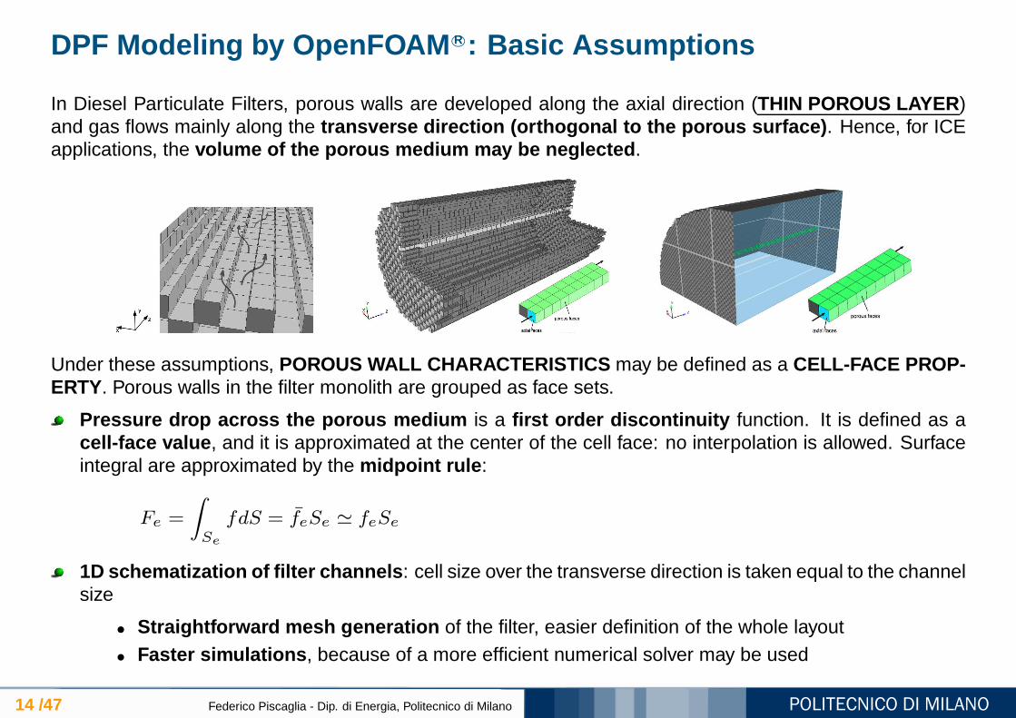
In Diesel Particulate Filters, porous walls are developed along the axial direction (THIN POROUS LAYER )and gas flows mainly along the transverse direction (orthogonal to the porous surface) . Hence, for ICEapplications, the volume of the porous medium may be neglected .
Under these assumptions, POROUS WALL CHARACTERISTICS may be defined as a CELL-FACE PROP-ERTY. Porous walls in the filter monolith are grouped as face sets.
Pressure drop across the porous medium is a first order discontinuity function. It is defined as acell-face value , and it is approximated at the center of the cell face: no interpolation is allowed. Surfaceintegral are approximated by the midpoint rule :
Fe =
∫
Se
fdS = feSe ≃ feSe
1D schematization of filter channels : cell size over the transverse direction is taken equal to the channelsize
• Straightforward mesh generation of the filter, easier definition of the whole layout• Faster simulations , because of a more efficient numerical solver may be used

Developed libraries, solvers and applications in OpenFOAM R©
15 /47 Federico Piscaglia - Dip. di Energia, Politecnico di Milano
DPF-SPECIFIC APPLICATIONS:
New application createDpfPatch for fully automatic imposition of open-closed checkerboard pattern onfilter inlet/outlet sections
Automatic algorithm for DPF mesh generation
DEVELOPED FOR DPF USE BUT SUITABLE FOR OTHER APPLICATIONS: Class porousFace for simulation of thin porous layers :
• Fully automatic setup of the DPF cases• Darcy-Forchheimer pressure drop and fluid-dynamic friction• Soot filtration and deposition model
New pseudo-staggered solvers for non-porous and porous com ponents , with or without soottransport:
• rhoSimplePorousFaceFoam• rhoPISOTransientPorousFaceFoam

Developed libraries, solvers and applications in OpenFOAM R©
16 /47 Federico Piscaglia - Dip. di Energia, Politecnico di Milano
GENERAL PURPOSE APPLICATIONS:
Class zoneExt: extracts face- and cellZones forpost-processing;
Post-processing tools to visualize cellZones andfaceZones and surface variables (e.g. facefluxes)
DPF-SPECIFIC APPLICATIONS:
New application createDpfPatch for fully auto-matic imposition of open-closed checkerboardpattern on filter inlet/outlet sections
Shell script for automatic DPF mesh generation.
DEVELOPED FOR DPF USE BUT SUITABLEFOR OTHER APPLICATIONS:
Class porousFace for simulation of thin porouslayers:
Fully automatic creation for DPF cases;
Darcy-Forchheimer pressure drop andfluid-dynamic friction;
Filtration model for soot.
New pseudo-staggered solvers for non-porous and porous components , with orwithout soot transport:
rhoSimplePorousFaceFoam
rhoTransientSimplePorousFaceFoam
transient PISO solver for flows throughporous media

Case Setup and Automatic Mesh Handling
17 /47 Federico Piscaglia - Dip. di Energia, Politecnico di Milano
The computational domain is partitioned into two regions, corresponding to different sub-domains:
FLUID REGION
- inlet pipe
- plug-ends
- filter channels
- outlet pipe
SOLID REGION
- filter segments
Any block of the computational mesh is generated separately by a grid generator. During this first step,all the inner cells (and their faces) in the computational domain are defined as fluid
Blocks are merged into one block
Plug-ends, filter channels and closed-ends in the monoliths are set as cell face properties in the DPF byAUTOMATIC ALGORITHMS developed as applications in the OpenFOAM R© technology

Case Setup
18 /47 Federico Piscaglia - Dip. di Energia, Politecnico di Milano
The three-dimensional mesh geometry of the monolith is generated from a 2D sketch; faceSetscustomization for DPF applications is performed by an automatic algorithm (createDpfFaceSets ):
inlet and outlet ends of the monolith show a typical “chessboard” arrange-ment, where channels are alternatively open and closed; cell-faces repre-senting the closed-ends of filter channels are automatically set as ”walls ”
plug ends are automatically generated by extruding inlet and outlet ends ofthe monolith and then adding the resulting mesh to the original one; theyhave non-permeable walls, that are automatically grouped and set as ”walls”
porosity is modeled as a cell-face property ; porous walls dividing inlet andoutlet channels of the monolith are grouped in a faceSet defined as ”porous”
The solid region for the DPF material and the cement strips is used tomodel the heat exchange to the surroundings
Porous class: a class to calculate pressure jumps across sur faces
19 /47 Federico Piscaglia - Dip. di Energia, Politecnico di Milano
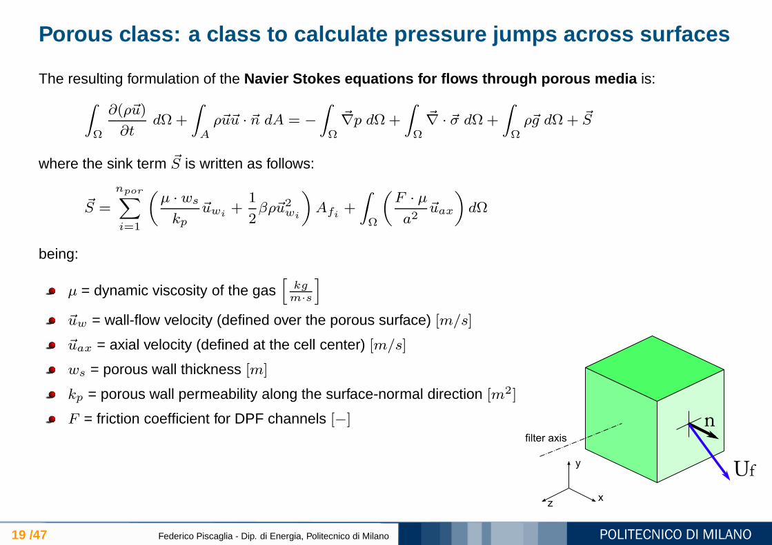
The resulting formulation of the Navier Stokes equations for flows through porous media is:∫
Ω
∂(ρ~u)
∂tdΩ+
∫
Aρ~u~u · ~n dA = −
∫
Ω
~∇p dΩ+
∫
Ω
~∇ · ~σ dΩ+
∫
Ωρ~g dΩ+ ~S
where the sink term ~S is written as follows:
~S =
npor∑
i=1
(
µ · ws
kp~uwi
+1
2βρ~u2wi
)
Afi +
∫
Ω
(
F · µ
a2~uax
)
dΩ
being:
µ = dynamic viscosity of the gas[
kgm·s
]
~uw = wall-flow velocity (defined over the porous surface) [m/s]
~uax = axial velocity (defined at the cell center) [m/s]
ws = porous wall thickness [m]
kp = porous wall permeability along the surface-normal direction [m2]
F = friction coefficient for DPF channels [−]

Variable Arrangement in OpenFOAM R©
20 /47 Federico Piscaglia - Dip. di Energia, Politecnico di Milano
Discretization in OpenFOAM R©is based on the collocated arrangement , that allows significant advan-tages in complicated solution domains, especially when the boundaries have slope discontinuities or theboundary conditions are discontinuous.
In the DPF mesh, velocity and pressures between neighbour cells (divided by the porous cell-face) maybe very different; hence, the pressure-velocity handling of the collocated variable arrangement may causethat mass is poorly conserved .
The problem does not occur if a staggered variable arrangement is used. A pseudo-staggered ap-proach has been used to preserve sharp value changes in pressure and velocity field between DPF chan-nels. The method mimics the operation of a solution procedure devised for a st aggered variablearrangement, but keeping the collocated variables .
Solver Implementation
21 /47 Federico Piscaglia - Dip. di Energia, Politecnico di Milano
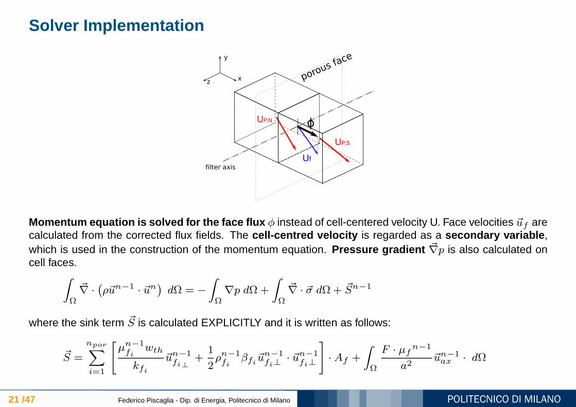
Momentum equation is solved for the face flux φ instead of cell-centered velocity U. Face velocities ~uf arecalculated from the corrected flux fields. The cell-centred velocity is regarded as a secondary variable ,which is used in the construction of the momentum equation. Pressure gradient ~∇p is also calculated oncell faces.
∫
Ω
~∇ ·(
ρ~un−1 · ~un)
dΩ = −
∫
Ω∇p dΩ+
∫
Ω
~∇ · ~σ dΩ+ ~Sn−1
where the sink term ~S is calculated EXPLICITLY and it is written as follows:
~S =
npor∑
i=1
[
µn−1fi
wth
kfi~un−1fi⊥
+1
2ρn−1fi
βfi~un−1fi⊥
· ~un−1fi⊥
]
·Af +
∫
Ω
F · µfn−1
a2~un−1ax · dΩ
Solver Implementation
22 /47 Federico Piscaglia - Dip. di Energia, Politecnico di Milano
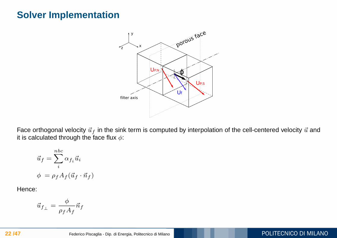
Face orthogonal velocity ~uf in the sink term is computed by interpolation of the cell-centered velocity ~u andit is calculated through the face flux φ:
~uf =nbc∑
i
αfi~ui
φ = ρfAf (~uf · ~nf )
Hence:
~uf⊥ =φ
ρfAf~nf

Solver Implementation
23 /47 Federico Piscaglia - Dip. di Energia, Politecnico di Milano
The resulting formulation of the sink term ~S is:
~S =
npor∑
i=1
µfn−1 wth
kfi
φfn−1
ρfn−1Af+
1
2β
(
φn−1f
)2
ρn−1f Af
2
·Af +
∫
Ω
F · µfn−1
4a~i3 ~i
T3 ~uax dΩ
Linear interpolation has been used to calculate over the cell face any other quantity (gas density ρfand dynamic viscosity µf for instance) originally defined over the cell volume.
Code has been implemented in a coordinate free formulation
Solver Implementation
24 /47 Federico Piscaglia - Dip. di Energia, Politecnico di Milano
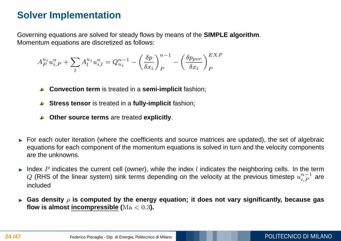
Governing equations are solved for steady flows by means of the SIMPLE algorithm .Momentum equations are discretized as follows:
Aui
P uni,P +∑
l
Aui
l uni,l = Qn−1ui
−
(
δp
δxi
)n−1
P
−
(
δppor
δxi
)EXP
P
Convection term is treated in a semi-implicit fashion;
Stress tensor is treated in a fully-implicit fashion;
Other source terms are treated explicitly .
For each outer iteration (where the coefficients and source matrices are updated), the set of algebraicequations for each component of the momentum equations is solved in turn and the velocity componentsare the unknowns.
Index P indicates the current cell (owner), while the index l indicates the neighboring cells. In the termQ (RHS of the linear system) sink terms depending on the velocity at the previous timestep un−1
i,P areincluded
Gas density ρ is computed by the energy equation; it does not vary significa ntly, because gasflow is almost incompressible ( Ma < 0.3).
Top-level Solver Implementation in OpenFOAM R©
25 /47 Federico Piscaglia - Dip. di Energia, Politecnico di Milano
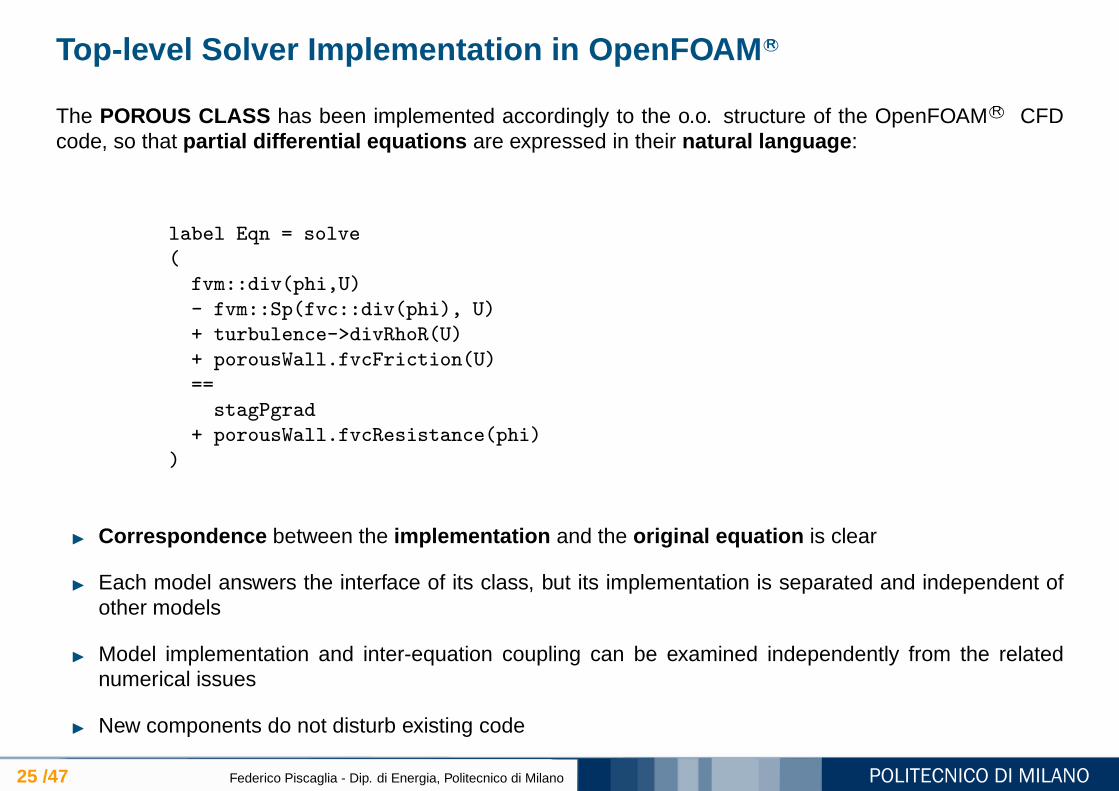
The POROUS CLASS has been implemented accordingly to the o.o. structure of the OpenFOAM R© CFDcode, so that partial differential equations are expressed in their natural language :
label Eqn = solve
(
fvm::div(phi,U)
- fvm::Sp(fvc::div(phi), U)
+ turbulence->divRhoR(U)
+ porousWall.fvcFriction(U)
==
stagPgrad
+ porousWall.fvcResistance(phi)
)
Correspondence between the implementation and the original equation is clear
Each model answers the interface of its class, but its implementation is separated and independent ofother models
Model implementation and inter-equation coupling can be examined independently from the relatednumerical issues
New components do not disturb existing code

Interaction between laminar and turbulent flow regions in DP Fs
26 /47 Federico Piscaglia - Dip. di Energia, Politecnico di Milano
Turbulence class has been extended in order to allow for switching off turbulence source terms in the NSequations within a single cell region, for a given cellSet. In the case studied, turbulence is not calculatedin the monolith channels, where the flow regime is laminar.
simulations were carried out by a transient PISO solver, where the porous class was included
Turbulence models
27 /47 Federico Piscaglia - Dip. di Energia, Politecnico di Milano
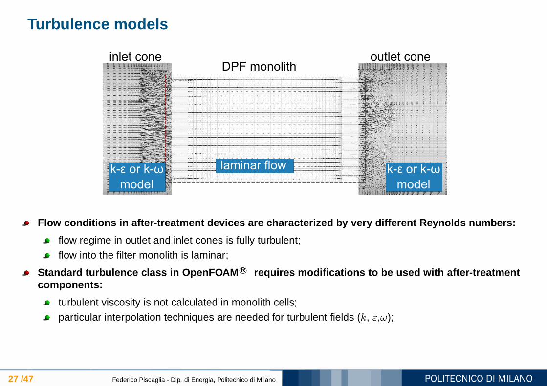
Flow conditions in after-treatment devices are characteri zed by very different Reynolds numbers:
flow regime in outlet and inlet cones is fully turbulent;flow into the filter monolith is laminar;
Standard turbulence class in OpenFOAM R© requires modifications to be used with after-treatmentcomponents:
turbulent viscosity is not calculated in monolith cells;particular interpolation techniques are needed for turbulent fields (k, ε,ω);
Turbulence models
28 /47 Federico Piscaglia - Dip. di Energia, Politecnico di Milano
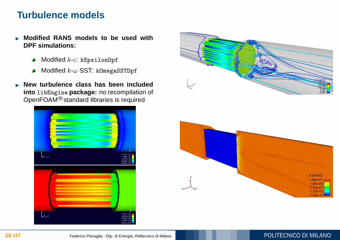
Modified RANS models to be used withDPF simulations:
Modified k-ε: kEpsilonDpf
Modified k-ω SST: kOmegaSSTDpf
New turbulence class has been includedinto libEngine package: no recompilation ofOpenFOAM R©standard libraries is required

Code validation
29 /47 Federico Piscaglia - Dip. di Energia, Politecnico di Milano
Table 1: Specification of the Filter Used in the Experi-ments and Simulations [10].
filter type EX-80 100/17channel length [mm] 114/165plug length [mm] 10channel width [mm] 2.28porous wall thickness, ws [mm] 0.432cell density [CPSI] 100porosity 48%mean pore size [µm] 12
Numerical simulations were carried out on a grid having 199260 computational cells (96462 hexahedra,2186 pyramids, 100612 tetrahedra); calculation of each operating point required approximately 7.5 CPUhours by an Intel Core Duo 2.8 GHz. Simulation time was about 5 hours as simulations ran in parallel on 2processors.
Flow conditions : pout = 101325 Pa, T = 300 K
Clean trap permeability of the porous medium kp= 8.2 · 10−13 m2, in order to match the experimentalpoint at the lowest flow rate ( V = 15 Nm3 /h)
kp was kept constant as the inlet flow rate was varied through the simulations
Code validation (clean trap)
30 /47 Federico Piscaglia - Dip. di Energia, Politecnico di Milano
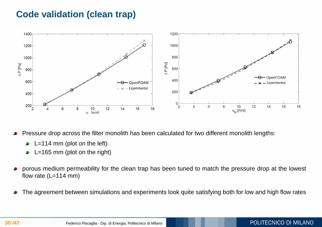
Pressure drop across the filter monolith has been calculated for two different monolith lengths:
L=114 mm (plot on the left)L=165 mm (plot on the right)
porous medium permeability for the clean trap has been tuned to match the pressure drop at the lowestflow rate (L=114 mm)
The agreement between simulations and experiments look quite satisfying both for low and high flow rates

Filter Hydrodynamics
31 /47 Federico Piscaglia - Dip. di Energia, Politecnico di Milano
Velocity field Pressure field

Filter Hydrodynamics
32 /47 Federico Piscaglia - Dip. di Energia, Politecnico di Milano
Filter channels may have a different number of filtrating walls :
internal channels have 4 filtrating walls
channels at the boundary may have 2 or 3 filtrating walls
Flow velocity and channel pressure are expected to be different for channels having a different number offiltrating walls: flow velocity and pressure field have been monitored for two di fferent inlet flow rates:15 Nm3/h and 70 Nm 3/h

Filter Hydrodynamics
33 /47 Federico Piscaglia - Dip. di Energia, Politecnico di Milano
15 Nm3/h
0 0.2 0.4 0.6 0.8 10
0.002
0.004
0.006
0.008
0.01
0.012
0.014
0.016
distance [−]
u w [m
/s]
2 filtrating walls
3 filtrating walls
4 filtrating walls
0 0.2 0.4 0.6 0.8 10
0.5
1
1.5
2
2.5
3
distance [−]u ax
[m/s
]
2 filtrating walls3 filtrating walls4 filtrating walls
0 0.2 0.4 0.6 0.8 11.013
1.0135
1.014
1.0145
1.015
1.0155
1.016x 10
5
distance [−]
p [P
a]
2 filtrating walls
3 filtrating walls
4 filtrating walls
wall-flow velocity axial velocity pressure
70 Nm3/h
0 0.2 0.4 0.6 0.8 10
0.02
0.04
0.06
0.08
0.1
distance [−]
Uw
[m
/s]
2 filtrating walls3 filtrating walls4 filtrating walls
0 0.02 0.04 0.06 0.08 0.1 0.120
5
10
15
distance [−]
Uax
[m/s
]
2 filtrating walls3 filtrating walls4 filtrating walls
0 0.02 0.04 0.06 0.08 0.1 0.121.01
1.012
1.014
1.016
1.018
1.02
1.022
1.024x 10
5
distance [−]
p [P
a]
2 filtrating walls3 filtrating walls4 filtrating walls
wall-flow velocity axial velocity pressure
Non-uniform distribution of the flow at filter ends
34 /47 Federico Piscaglia - Dip. di Energia, Politecnico di Milano
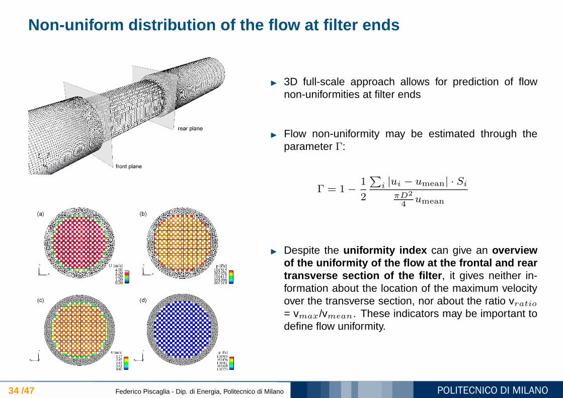
3D full-scale approach allows for prediction of flownon-uniformities at filter ends
Flow non-uniformity may be estimated through theparameter Γ:
Γ = 1−1
2
∑
i |ui − umean| · Si
πD2
4umean
Despite the uniformity index can give an overviewof the uniformity of the flow at the frontal and reartransverse section of the filter , it gives neither in-formation about the location of the maximum velocityover the transverse section, nor about the ratio vratio= vmax/vmean. These indicators may be important todefine flow uniformity.

Non-uniform distribution of the flow at filter ends
35 /47 Federico Piscaglia - Dip. di Energia, Politecnico di Milano
3D full-scale approach allows for prediction of flownon-uniformities at filter ends
Flow non-uniformity may be estimated through theparameter Γ:
Γ = 1−1
2
∑
i |ui − umean| · Si
πD2
4umean
Despite the uniformity index can give an overviewof the uniformity of the flow at the frontal and reartransverse section of the filter , it gives neither in-formation about the location of the maximum velocityover the transverse section, nor about the ratio vratio= vmax/vmean. These indicators may be important todefine flow uniformity.

Soot transport and deposition
36 /47 Federico Piscaglia - Dip. di Energia, Politecnico di Milano
Soot is transported as a chemical specie : previ-ous studies [3, 2] indicates that Stokes number ofsoot particles in engine exhaust gas flow is very low(St < 10−4);
∂(
ρ~Y)
∂t+ ~∇ · (ρ~u~Y ) + ~D = 0
Soot is removed by an implicit sink term ~D ap-plied on porous faces: the amount of soot removalis determined by the filtration efficiency of that par-ticular face;
During filter loading the trapped soot particleschange the following quantities, defined as porous-cell face properties:
soot cake thicknesscollection efficiencyhydrodynamic resistance (Darcy coefficient)
Soot transport and deposition
37 /47 Federico Piscaglia - Dip. di Energia, Politecnico di Milano
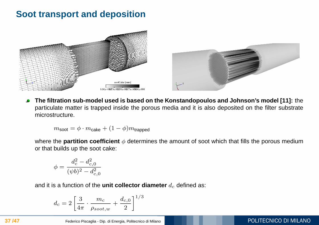
The filtration sub-model used is based on the Konstandopoulo s and Johnson’s model [11]: theparticulate matter is trapped inside the porous media and it is also deposited on the filter substratemicrostructure.
msoot = φ ·mcake + (1− φ)mtrapped
where the partition coefficient φ determines the amount of soot which that fills the porous mediumor that builds up the soot cake:
φ =d2c − d2c,0
(ψb)2 − d2c,0
and it is a function of the unit collector diameter dc defined as:
dc = 2
[
3
4π·
mc
ρsoot,w+dc,0
2
]1/3

Soot transport and deposition
38 /47 Federico Piscaglia - Dip. di Energia, Politecnico di Milano
Local wall porosity ε change continuously as filtra-tion proceeds:
ε = 1−
(
dc
dc,0
)3
(1− ε0)
Collection efficiency is determined by two concur-ring mechanisms:
Direct interception by spherical collectors ηR
Brownian diffusion ηD
E = 1−exp
[
−3(1− ε)(ηD + ηR − ηDηR)wsoot
4εdc
]
Wall resistance is given by the sum of porous walland soot cake:
∆P =
[
wwall
kwall+wsoot
ksoot
]
· µw · un
Wall permeability changes accordingly to thewall porosity:
kwall = kwall,0
(
dc
dc,0
)2 f(ε)
f(ε0)·1− ε0
1− ε
Partially Reflecting Open End
39 /47 Federico Piscaglia - Dip. di Energia, Politecnico di Milano
pressure probes
cylinder head
lift sensor
carriage
mass
valve
pressure probe
(in-cylinder pressure)
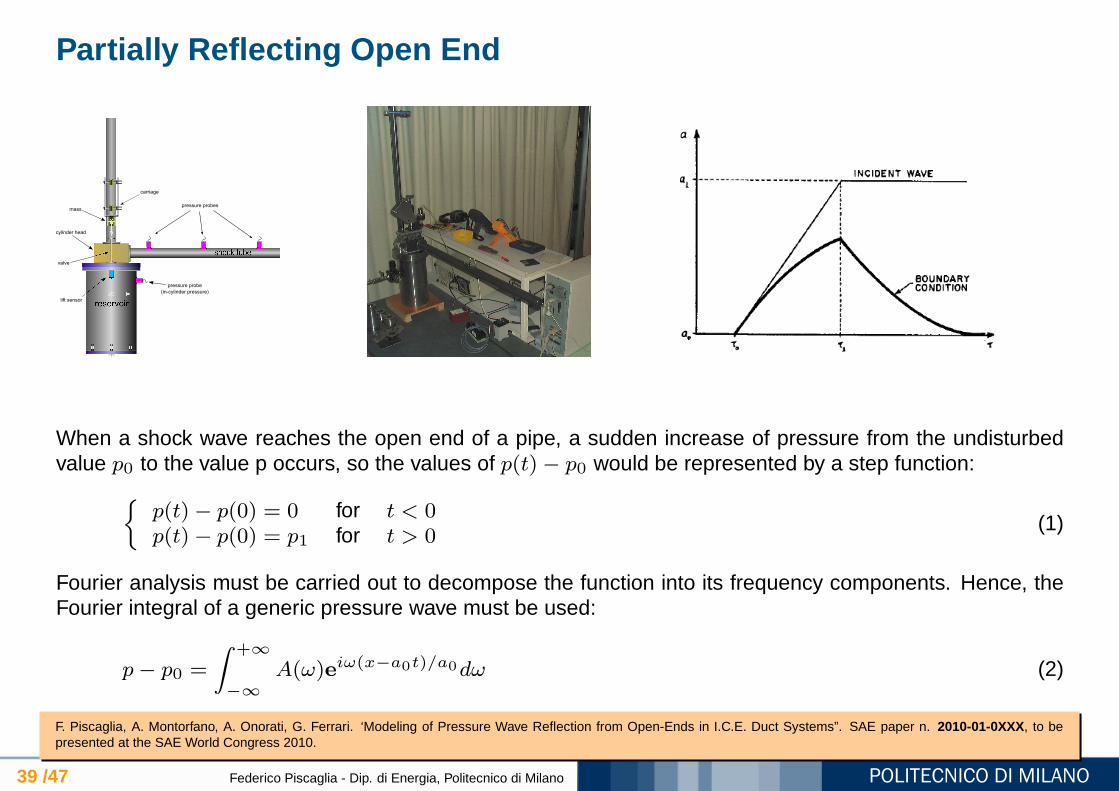
When a shock wave reaches the open end of a pipe, a sudden increase of pressure from the undisturbedvalue p0 to the value p occurs, so the values of p(t)− p0 would be represented by a step function:
p(t)− p(0) = 0 for t < 0p(t)− p(0) = p1 for t > 0
(1)
Fourier analysis must be carried out to decompose the function into its frequency components. Hence, theFourier integral of a generic pressure wave must be used:
p− p0 =
∫ +∞
−∞
A(ω)eiω(x−a0t)/a0dω (2)
F. Piscaglia, A. Montorfano, A. Onorati, G. Ferrari. ‘Modeling of Pressure Wave Reflection from Open-Ends in I.C.E. Duct Systems”. SAE paper n. 2010-01-0XXX, to bepresented at the SAE World Congress 2010.
Partially Reflecting Open End
40 /47 Federico Piscaglia - Dip. di Energia, Politecnico di Milano
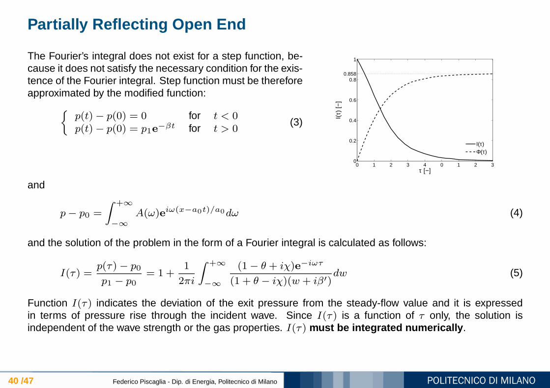
The Fourier’s integral does not exist for a step function, be-cause it does not satisfy the necessary condition for the exis-tence of the Fourier integral. Step function must be thereforeapproximated by the modified function:
p(t)− p(0) = 0 for t < 0p(t)− p(0) = p1e−βt for t > 0
(3)
0 1 2 3 4 0 1 2 30
0.2
0.4
0.6
0.80.858
1
τ [−]
I(τ)
[−]
I(τ)Φ(τ)
and
p− p0 =
∫ +∞
−∞
A(ω)eiω(x−a0t)/a0dω (4)
and the solution of the problem in the form of a Fourier integral is calculated as follows:
I(τ) =p(τ)− p0
p1 − p0= 1 +
1
2πi
∫ +∞
−∞
(1− θ + iχ)e−iωτ
(1 + θ − iχ)(w + iβ′)dw (5)
Function I(τ) indicates the deviation of the exit pressure from the steady-flow value and it is expressedin terms of pressure rise through the incident wave. Since I(τ) is a function of τ only, the solution isindependent of the wave strength or the gas properties. I(τ) must be integrated numerically .
Partially Reflecting Open End
41 /47 Federico Piscaglia - Dip. di Energia, Politecnico di Milano
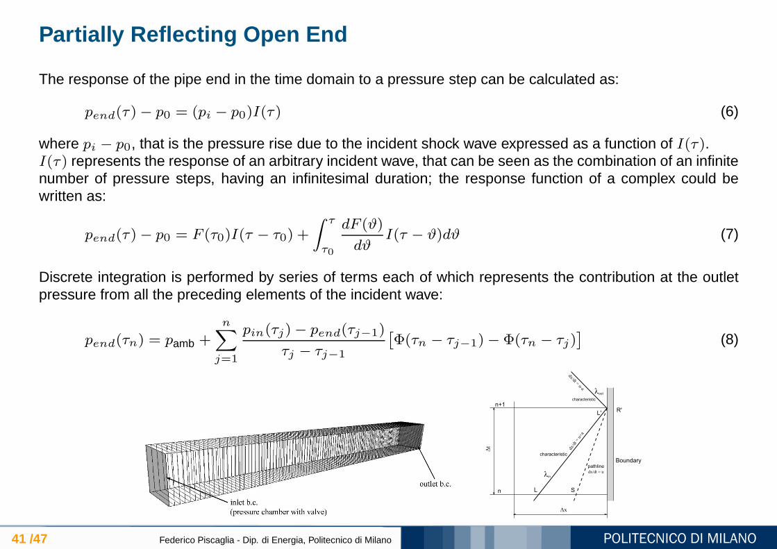
The response of the pipe end in the time domain to a pressure step can be calculated as:
pend(τ)− p0 = (pi − p0)I(τ) (6)
where pi − p0, that is the pressure rise due to the incident shock wave expressed as a function of I(τ).I(τ) represents the response of an arbitrary incident wave, that can be seen as the combination of an infinitenumber of pressure steps, having an infinitesimal duration; the response function of a complex could bewritten as:
pend(τ)− p0 = F (τ0)I(τ − τ0) +
∫ τ
τ0
dF (ϑ)
dϑI(τ − ϑ)dϑ (7)
Discrete integration is performed by series of terms each of which represents the contribution at the outletpressure from all the preceding elements of the incident wave:
pend(τn) = pamb +n∑
j=1
pin(τj)− pend(τj−1)
τj − τj−1
[
Φ(τn − τj−1)− Φ(τn − τj)]
(8)
Boundarypathline
characteristic
characteristic
n+1
n L S
L'R'
λin
λout
Δx
Δt
dx/d
t = u
+a
dx/d
t = u
-a
dx/dt = u
Partially Reflecting Open End VS const Pressure Model
42 /47 Federico Piscaglia - Dip. di Energia, Politecnico di Milano
Boundarypathline
characteristic
characteristic
n+1
n L S
L'R'
λin
λout
Δx
Δt
dx/d
t = u
+a
dx/d
t = u
-a
dx/dt = u
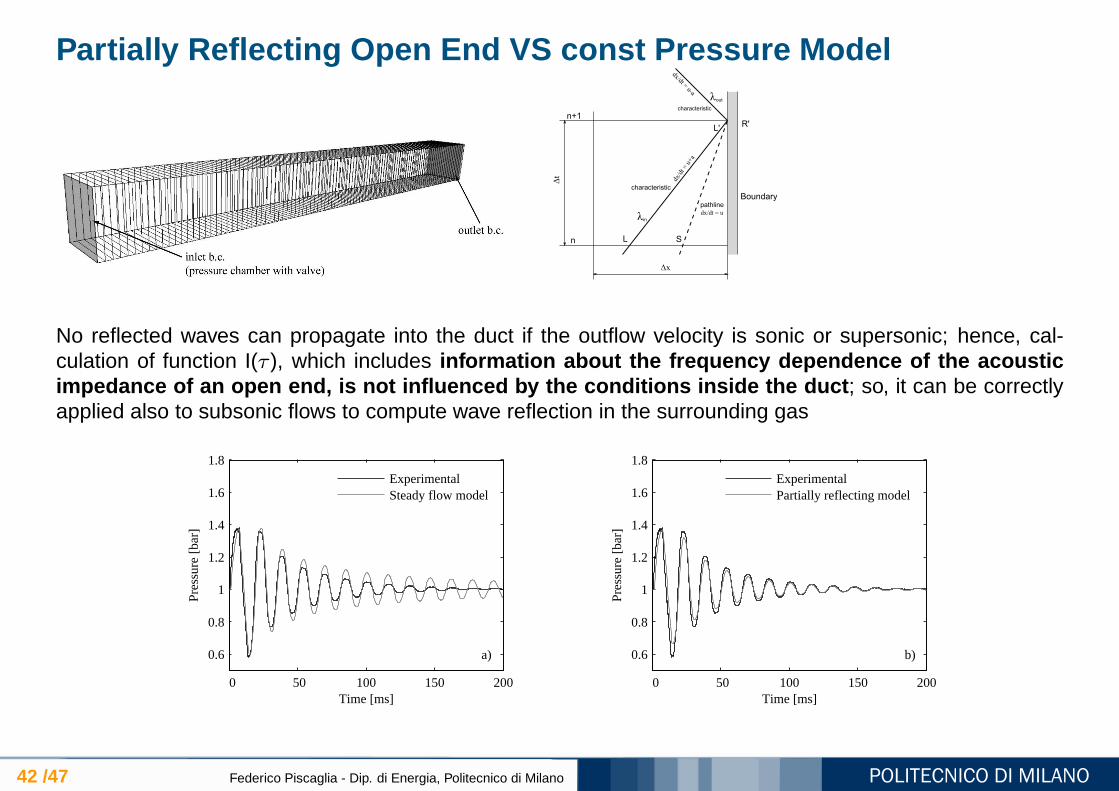
No reflected waves can propagate into the duct if the outflow velocity is sonic or supersonic; hence, cal-culation of function I(τ ), which includes information about the frequency dependence of the acousticimpedance of an open end, is not influenced by the conditions i nside the duct ; so, it can be correctlyapplied also to subsonic flows to compute wave reflection in the surrounding gas
0 50 100 150 200
0.6
0.8
1
1.2
1.4
1.6
1.8
Time [ms]
Pres
sure
[ba
r]
ExperimentalSteady flow model
a)
0 50 100 150 200
0.6
0.8
1
1.2
1.4
1.6
1.8
Time [ms]
Pres
sure
[ba
r]
ExperimentalPartially reflecting model
b)
Current development: acoustic simulation
43 /47 Federico Piscaglia - Dip. di Energia, Politecnico di Milano
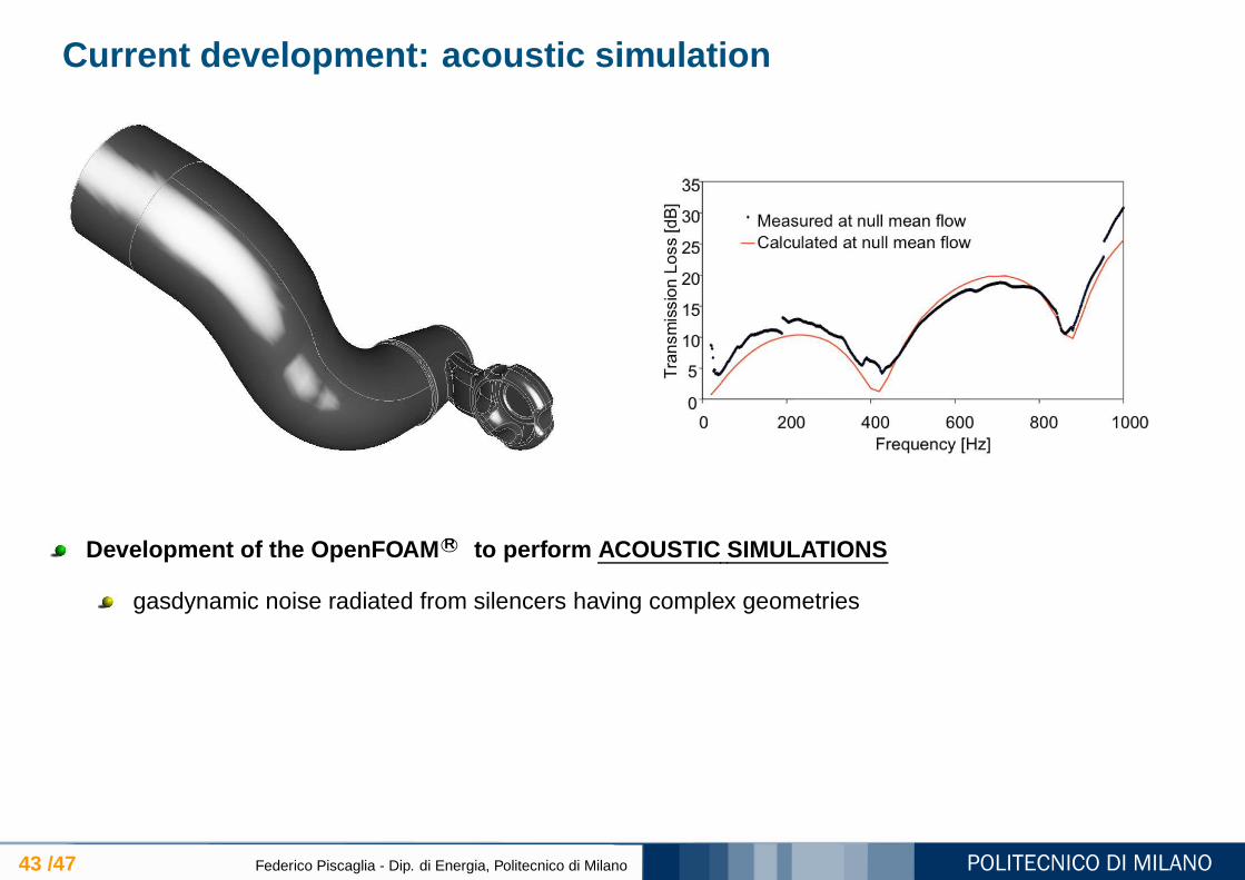
Development of the OpenFOAM R© to perform ACOUSTIC SIMULATIONS
gasdynamic noise radiated from silencers having complex geometries

Current development
44 /47 Federico Piscaglia - Dip. di Energia, Politecnico di Milano
Development of the code to perform simulation of SCR systems in OpenFOAM R©
Numerical Solvers :
Unsteady compressible solver to calculate filter pressure drop during engine transientsFully implicit solver (block-matrix solver): pressure drop across the porous cell face is written as afunction of the velocity u
n+1 at the current time-step, in order to improve stability and performance
Submodels for simulation of DPFs:
THERMAL and CHEMICAL models implemented as OpenFOAM R© classes for filter regeneration
Development of the OpenFOAM R© to perform ACOUSTIC SIMULATIONS
gasdynamic noise radiated from silencers having complex geometries
FUTURE WORK: LES modeling

45 /47 Federico Piscaglia - Dip. di Energia, Politecnico di Milano
Thanks for your attention!

46 /47 Federico Piscaglia - Dip. di Energia, Politecnico di Milano
Federico Piscaglia , Ph.D.Assistant Professor of Internal Combustion Engines
CONTACT INFORMATION
Address Dipartimento di Energia, Politecnico di Milano (campus Bovisa)via Lambruschini 4, 20156 Milano (ITALY)
E-Mail: [email protected]: (+39) 02 2399 8620Fax: (+39) 02 2399 3863Web page: http://www.engines.polimi.it/

References
47 /47 Federico Piscaglia - Dip. di Energia, Politecnico di Milano
[1] F. Piscaglia, A. Montorfano, and A. Onorati . Development of a Multi-Dimensional Parallel Solver for Full-Scale DPF Modeling in OpenFOAM. SAE paper n.2009-01-1965, SAE 2009 International Powertrains, Fuels and Lubricants Meeting, June 15-17, 2009, Florence, Italy, 2009, 2009.
[2] F. Piscaglia, A. Onorati, C. J. Rutland, and D. E. Foster . “Multi-dimensional modeling of the soot deposition mechanism in diesel particulate filters”. In SAETransactions, Journal of Fuel & Lubricants. SAE paper n. 2008-01-0444, SAE 2008 Int. Congress & Exp. (Detroit, Michigan), 2008.
[3] F. Piscaglia, C. J. Rutland, and D. E. Foster . “Development of a CFD model to study the hydrodynamic characteristics and the soot deposition mechanism on theporous wall of a diesel particulate filter”. SAE paper n. 2005-01-0963, SAE 2005 Int. Congress & Exp. (Detroit, Michigan), 2005.
[4] G. Rudinger . Wave Diagrams for Nonsteady Flow in Ducts. D. Van Nostrand Company (Canada), Ltd., 1955.
[5] F. Piscaglia and G. Ferrari . A novel 1d approach for the simulation of unsteady reacting flows in diesel exhaust after-treatment systems. Energy, 34 (12):2051–2062,2009.
[6] A. Konstandopoulos, M. Kostoglou, D. Zarvalis, P. Housiada , and N. Vlachos . ”Multichannel simulation of soot oxidation in diesel particulate filters”. SAE paper n.2003-01-0839, SAE 2003 Int. Congress & Exp. (Detroit, Michigan), 2003.
[7] G. Koltsakis, O. Haralampous, N. Margaritis, Z. Samaras, C. Vogt, E. Ohara, Y. Watanabe, and T. Mizutani . “3-Dimensional modeling of the regeneration in SiCparticulate filters”. SAE Paper n. 2005-01-0953, SAE 2005 Int. Congress & Exp. (Detroit, Michigan), 2005.
[8] AVL List GmbH. 2005.
[9] C. Hinterberger, M. Olesen, and R. Kaiser . “3D Simulation of Soot Loading and Regeneration of Diesel Particulate Filter Systems”. 2007.
[10] M. Masoudi, A. Heibel, and P. Then . Predicting pressure drop of wall-flow diesel particulate filters – theory and experiment. SAE paper n. 2000-01-1084, SAE 2000Int. Congress & Exp. (Detroit, Michigan), 2000.
[11] A. G. Konstandopoulos and J. H. Johnson . “Wall-flow diesel particulate filters - their pressure drop and collection efficiency”. SAE paper n. 890405, SAE 1989 Int.Congress & Exp. (Detroit, Michigan), 1989.