liability for aircraft components – including case studies ... · pdf fileliability for...
TRANSCRIPT
Liability for aircraft components – including case studies - how not to get fatigued!
Evening Seminar – NSW Branch Aviation Law Association of Australia and New Zealand
Thursday 16 July 2015
Dr William A J Higgs & Geoffrey Parker SC
Elizabeth Street Chambers

Warning
There is more aeronautical knowledge than law in this presentation.

Take away messages
Like in all litigious matters one has to have a case theory –
case theory will depend in large part on the correct identification of the cause of the aircraft crash
It the blueprint from which you will conduct your case
Here lies the problem ! – the identification of actual cause is difficult (one or multiple causes)
Identification needs to be specific rather than general
Pleading negligent design versus pleading a cause of action relating to what actually happened or what was the actual cause
In large part, it is what the experts say backed by hard science?

Take away messages
Identification of the relevant expert should depend on your preliminary thesis as the cause of the accident (the ‘loop’)
This process is ‘circular’ because you wont know the actual cause until you engage the relevant expert
Metallurgist versus mechanical or aeronautical engineer versus LAME – don’t ask a aero eng to opine on fracture and fatigue, don’t ask a metallurgist to opine on aircraft design
Fracture / fatigue (metallurgist) or design (aeronautical/mechanical engineer), non manufactured part (LAME/engineer)
Once cause of accident is identified then one can plead on the basis of the applicable law.
One of the purposes of this presentation will give you some added knowledge about aircraft engineering concepts to enable you to close the ‘loop’ quicker to save costs searching for experts or more relevantly, the right one/s and conduct the litigation more efficiency (CPA)
Applicable law
The hypothesis is that a little bit of aircraft engineering knowledge would assist in identifying the cause of the crash - specifically by shaping your preliminary thesis and identification of experts – ultimately to guide you in ascertaining the cause of the crash.
Then it is a case of deciding on the applicable law……………whether it be all or some of the following:
Australian Consumer Law - ‘safety defect’
Trade Practices Act 1974 - ‘defect’
Negligence
Contract

Take away messages - knowledge
What engineering/aeronautical knowledge do you need to close the ‘loop’
How aircraft stay in the air – the basic principles
How aerodynamic loads are transmitted from within the aircraft structure such as the critical conduits for load transmissionsuch as lugs and fasteners
The nature of the load transmission mechanism ie shear forces, clamping forces etc
Most common failure mechanisms
Its is extremely rare that aircraft parts fail due to faulty design
Its is extremely rare that aircraft fail due to overloading
Incorrect use of materials, problems introduced in manufacture process; perhaps
Fracture and then fatigue failure; almost always
Design rationale or theory applicable to aircraft design
Basic principles of aircraft structures
Concepts of safe life, fail safe and damage tolerance
Fracture and fatigue principles - key
Part I Part II
How aircraft stay in the air
Flight envelope
Structure
Fracture & Fatigue
• Case study – Crash of Robinson R-22 Mariner II helicopter (VH-MIB) on 30 May 2004
• Legal aspects

How aircraft stay in the air
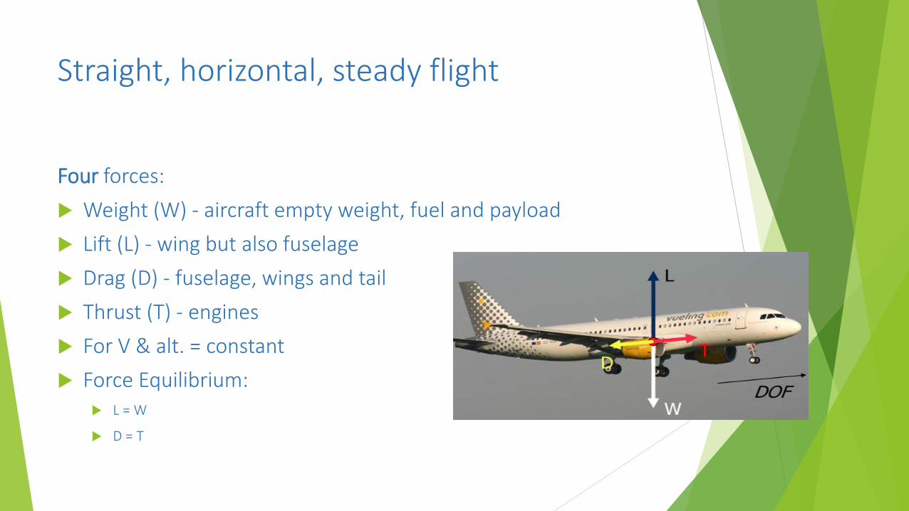
Straight, horizontal, steady flight
Four forces:
Weight (W) - aircraft empty weight, fuel and payload
Lift (L) - wing but also fuselage
Drag (D) - fuselage, wings and tail
Thrust (T) - engines
For V & alt. = constant
Force Equilibrium: L = W
D = T
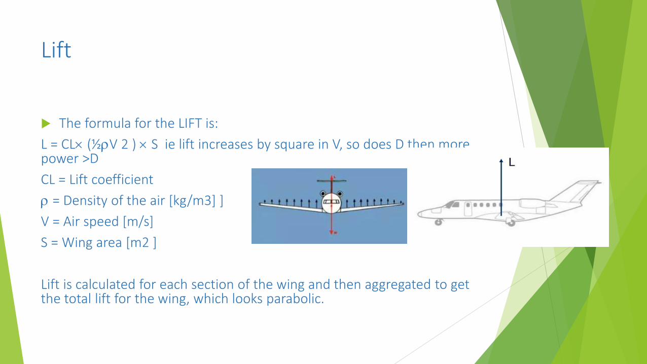
Lift
The formula for the LIFT is:
L = CL (½V 2 ) S ie lift increases by square in V, so does D then more power >D
CL = Lift coefficient
= Density of the air [kg/m3] ]
V = Air speed [m/s]
S = Wing area [m2 ]
Lift is calculated for each section of the wing and then aggregated to get the total lift for the wing, which looks parabolic.
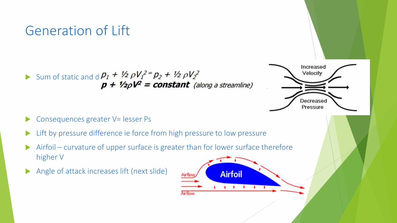
Generation of Lift
Sum of static and dynamic pressure remains constant
Consequences greater V= lesser Ps
Lift by pressure difference ie force from high pressure to low pressure
Airfoil – curvature of upper surface is greater than for lower surface therefore higher V
Angle of attack increases lift (next slide)
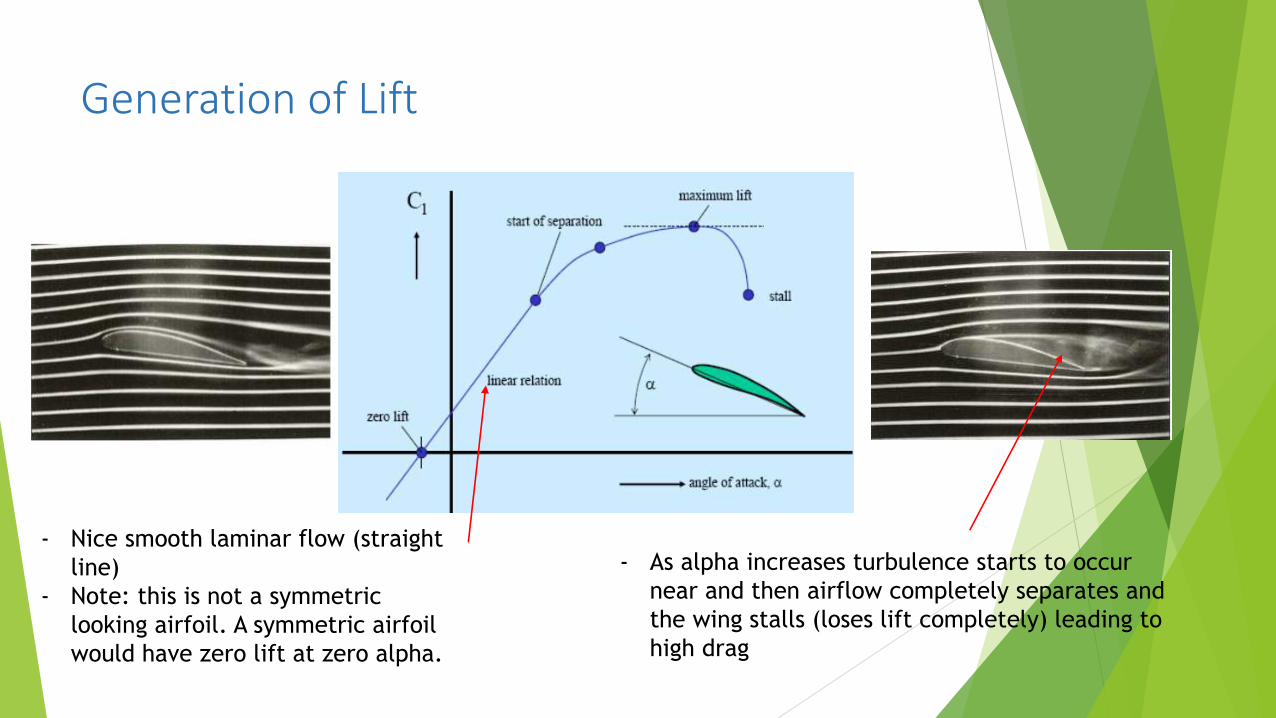
Generation of Lift
- As alpha increases turbulence starts to occur
near and then airflow completely separates and
the wing stalls (loses lift completely) leading to
high drag
- Nice smooth laminar flow (straight
line)
- Note: this is not a symmetric
looking airfoil. A symmetric airfoil
would have zero lift at zero alpha.

Load transmission

Transmission of lift
All lift force is transmitted through lugs (shown in red)
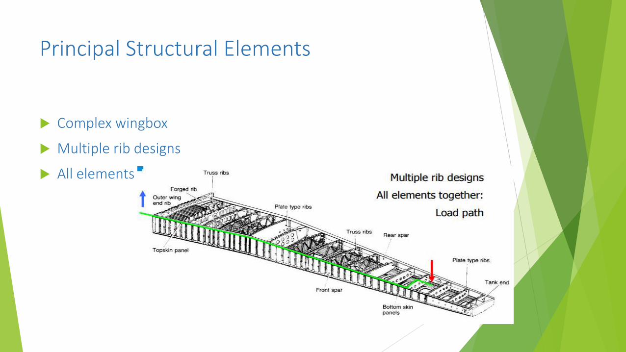
Principal Structural Elements
Complex wingbox
Multiple rib designs
All elements together: Load path

Bolted Joints

Flight Envelope
Flight Envelope
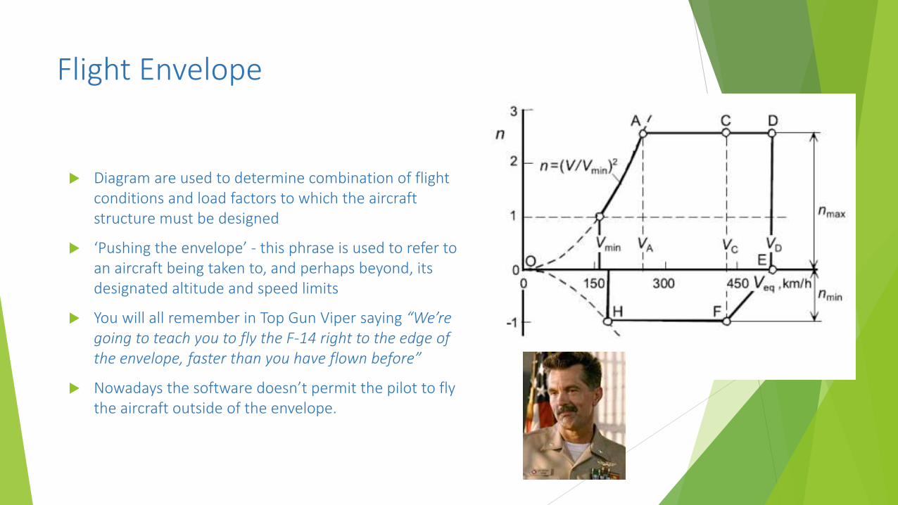
Diagram are used to determine combination of flight conditions and load factors to which the aircraft structure must be designed
‘Pushing the envelope’ - this phrase is used to refer to an aircraft being taken to, and perhaps beyond, its designated altitude and speed limits
You will all remember in Top Gun Viper saying “We’re going to teach you to fly the F-14 right to the edge of the envelope, faster than you have flown before”
Nowadays the software doesn’t permit the pilot to fly the aircraft outside of the envelope.

Flight Envelope
China Airlines Flight 006 damaged by going outside its flight envelope to gain control after a drop of 3,000 m in 20 seconds – resulting from disconnection of autopilot and pilot error resulting in 5 g pull out – would have been fun!
Loads – use of a V-n diagram
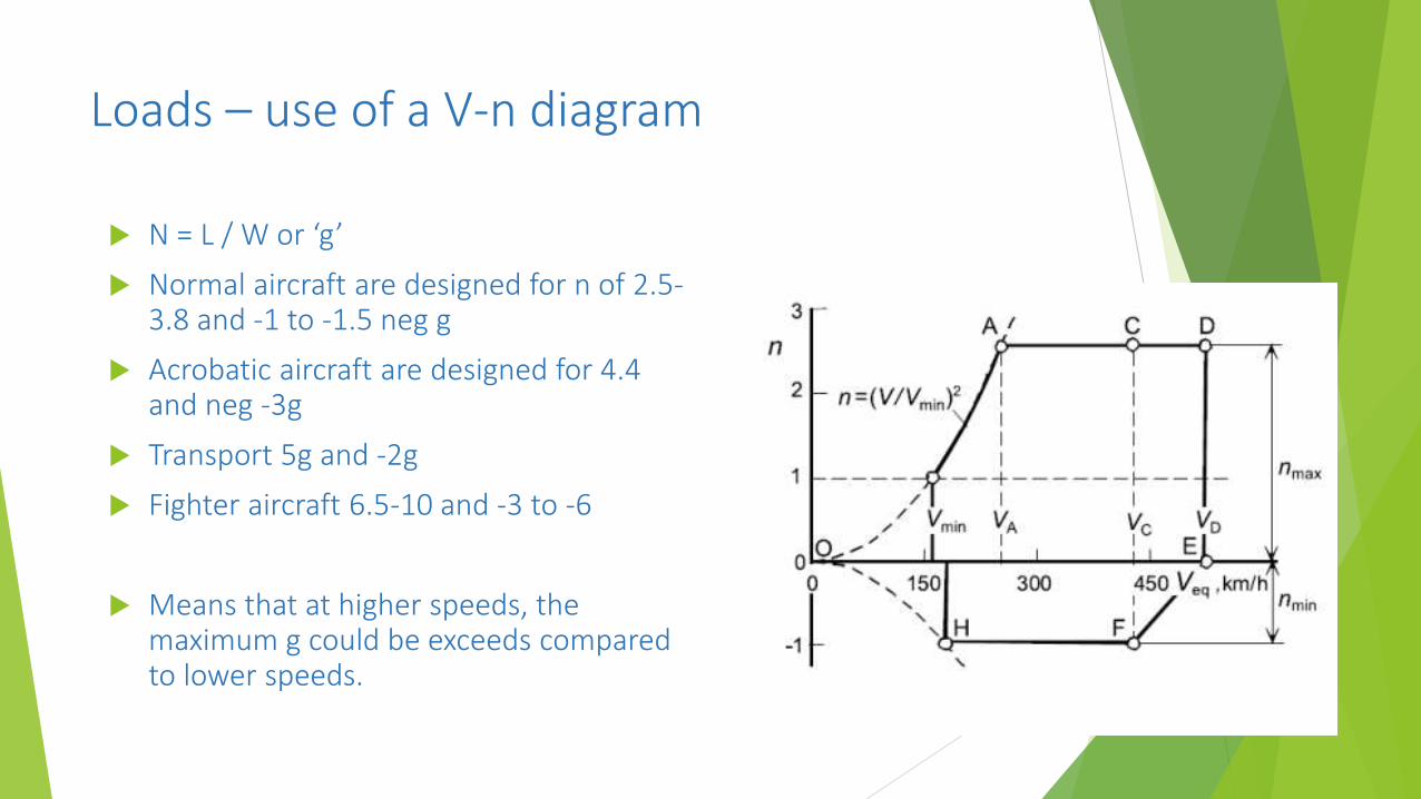
N = L / W or ‘g’
Normal aircraft are designed for n of 2.5-3.8 and -1 to -1.5 neg g
Acrobatic aircraft are designed for 4.4 and neg -3g
Transport 5g and -2g
Fighter aircraft 6.5-10 and -3 to -6
Means that at higher speeds, the maximum g could be exceeds compared to lower speeds.
Loads
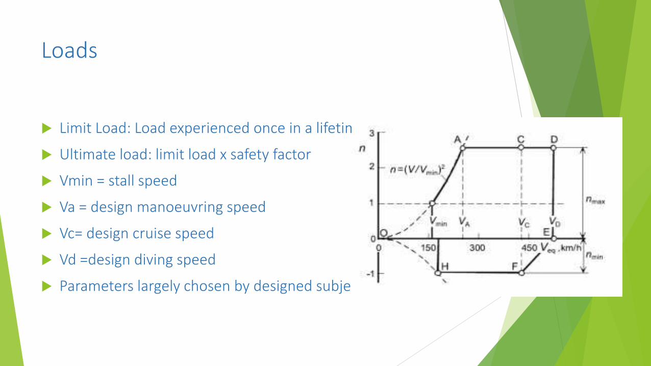
Limit Load: Load experienced once in a lifetime
Ultimate load: limit load x safety factor
Vmin = stall speed
Va = design manoeuvring speed
Vc= design cruise speed
Vd =design diving speed
Parameters largely chosen by designed subject to conditions

Structure

Anatomy of a structure
A structure is an assembly of multiple structural elements Each element participates in (some of) the functions of the structure
Structural elements are joined together
Most structural elements are derivatives of a beam
Goal is to minimise weight
So less lift required
Means less drag
Means less thrust
Means less fuel

From Truss to Beam
In the beginning of flight, aircraft structures were truss structures. For aerodynamic reasons they were closed with fabric.
The basic truss is very simple, elegant and light weight
If true hinges, any rotation will ? Prevent rotation by welding hinges
Still some distortionMore elegant? No
distortion
Aircraft structures
are built from these
From Truss to Beam
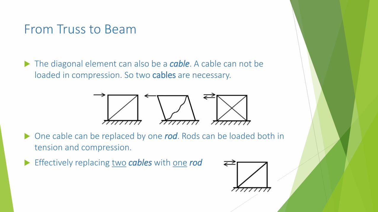
The diagonal element can also be a cable. A cable can not be loaded in compression. So two cables are necessary.
One cable can be replaced by one rod. Rods can be loaded both in tension and compression.
Effectively replacing two cables with one rod

From Truss to Beam
What happens when two diagonal rods are used? What are the advantages and disadvantages?
The structure becomes: - more difficult to assemble (no hinge at crossing), -heavier (2 bars)?
There is one advantage however, the structure has some “reserve”. One rod may fail but there is redundancy- fail safe structure
From Truss to Beam
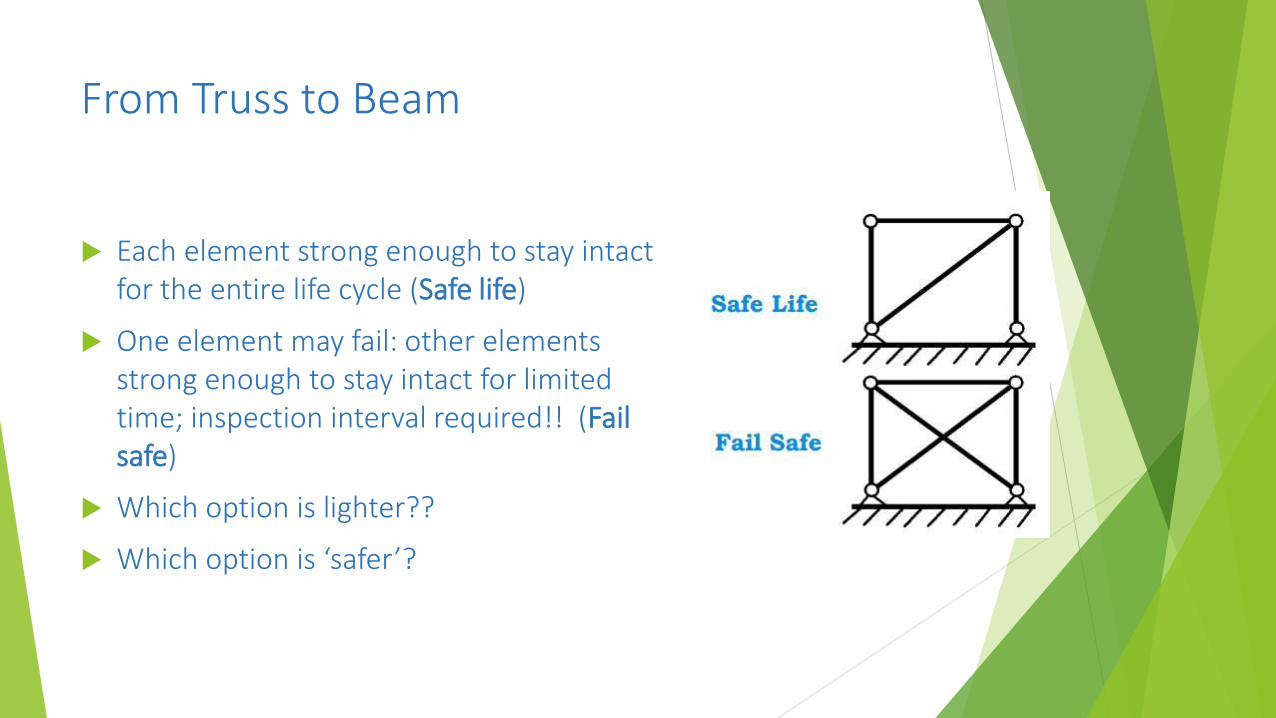
Each element strong enough to stay intact for the entire life cycle (Safe life)
One element may fail: other elements strong enough to stay intact for limited time; inspection interval required!! (Fail safe)
Which option is lighter??
Which option is ‘safer’?

From Truss to Beam
The rod can be replaced by a thin sheet or skin.

From Truss to Beam - transformation
Beam comprised of trusses
‘Wire braced’ structure
Combination of rods and wires
Increasing thickness of the rods to the left - WHY?
This is not truss for the vertical rods and wires – WHY NOT?
From Truss to Beam - transformation
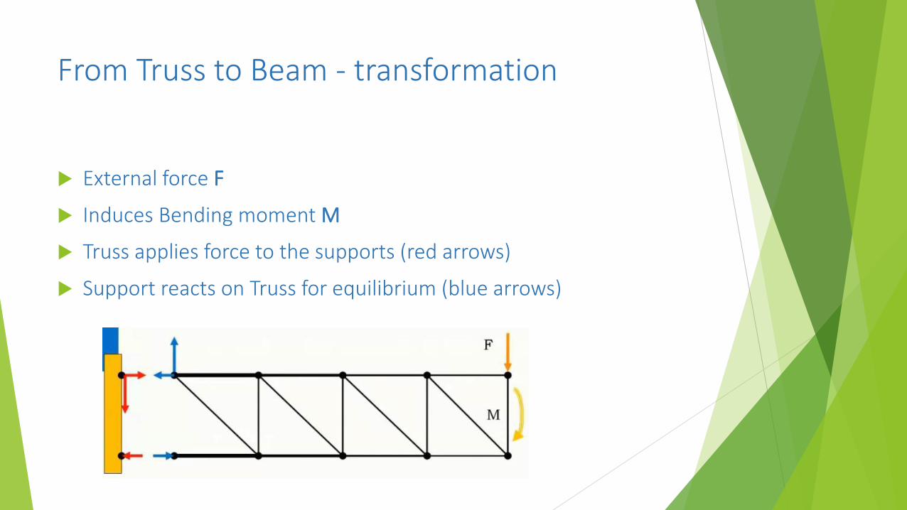
External force F
Induces Bending moment M
Truss applies force to the supports (red arrows)
Support reacts on Truss for equilibrium (blue arrows)

From Truss to Beam – transformation complete!
Truss can be replaced by sheet metal
Web plate instead of diagonal tubes
Web plate – shear forces; flanges– tension and compression forces

From Truss to Beam
When applying high forces on the structure, buckling starts. Compression forces cause local buckling of sheet
Elastic buckling is no Failure! Only reduced compression load carrying capabilities. Tensile forces are fully carried.
So long as stresses are within limits of the material the buckling is not problematic
Although it can be quite scary to see the buckling happening!

From Truss to Beam
No its not a full fuel tank!
Skin buckling due to shear loads
Perfectly safe Yes/No?

Typical wing or fuselage support structure
This is an example of plastic buckling = Failure!!
Note the local buckling of the flange on the top flange surface

Principal Structural Elements
Principal Structural Element – primary structure – carry loads -failure is/can be catastrophic
Non-principal structural elements – secondary structures failure is not catastrophic (e.g. fairings, some hatches)
Most Structural Elements are “beamlike” elements
Principal Structural Elements
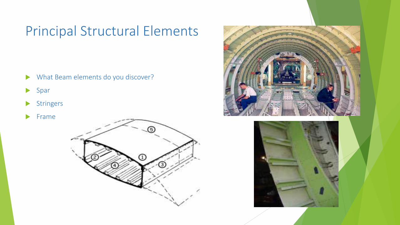
What Beam elements do you discover?
Spar
Stringers
Frame

Failure behavior materials
Within the limits of load diagram,
Material should not fail
Metal should not yield
Composite should not damage

Fracture & Fatigue
Aloha flight 243. The accident involved an explosive decompression in a 19 year old Boeing 737-200 aircraft on 28 April 1988. According to the United States National Transportation Safety Board (NTSB) accident report, the aircraft had 35,496 airframe flight hours and 89,680 flight cycles, which is an average flight time of 25 minutes.

Fatigue
Fatigue leads to failure of structures.
Fatigue is critical in load transmission pathways.
Dynamic loading – repetitive – leads to fatigue failure
Unavoidable in aircraft structures to flight cycles (landing and takeoff; rotation; variable loading on Aircraft due to aerobatics for instance)
Example: Paperclip - try to break one! the paper clip will not break if only bent once, however, if it is repeatedly loaded, it will eventually break
Every time you bend the paper clip microscopic damage occurs
(Repetitive) forces are always smaller than breaking force destroys the part!!
Fracture and Fatigue
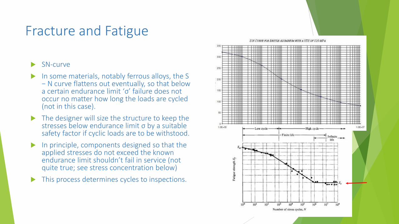
SN-curve
In some materials, notably ferrous alloys, the S − N curve flattens out eventually, so that below a certain endurance limit ‘σ’ failure does not occur no matter how long the loads are cycled (not in this case).
The designer will size the structure to keep the stresses below endurance limit σ by a suitable safety factor if cyclic loads are to be withstood.
In principle, components designed so that the applied stresses do not exceed the known endurance limit shouldn’t fail in service (not quite true; see stress concentration below)
This process determines cycles to inspections.
Fracture and Fatigue
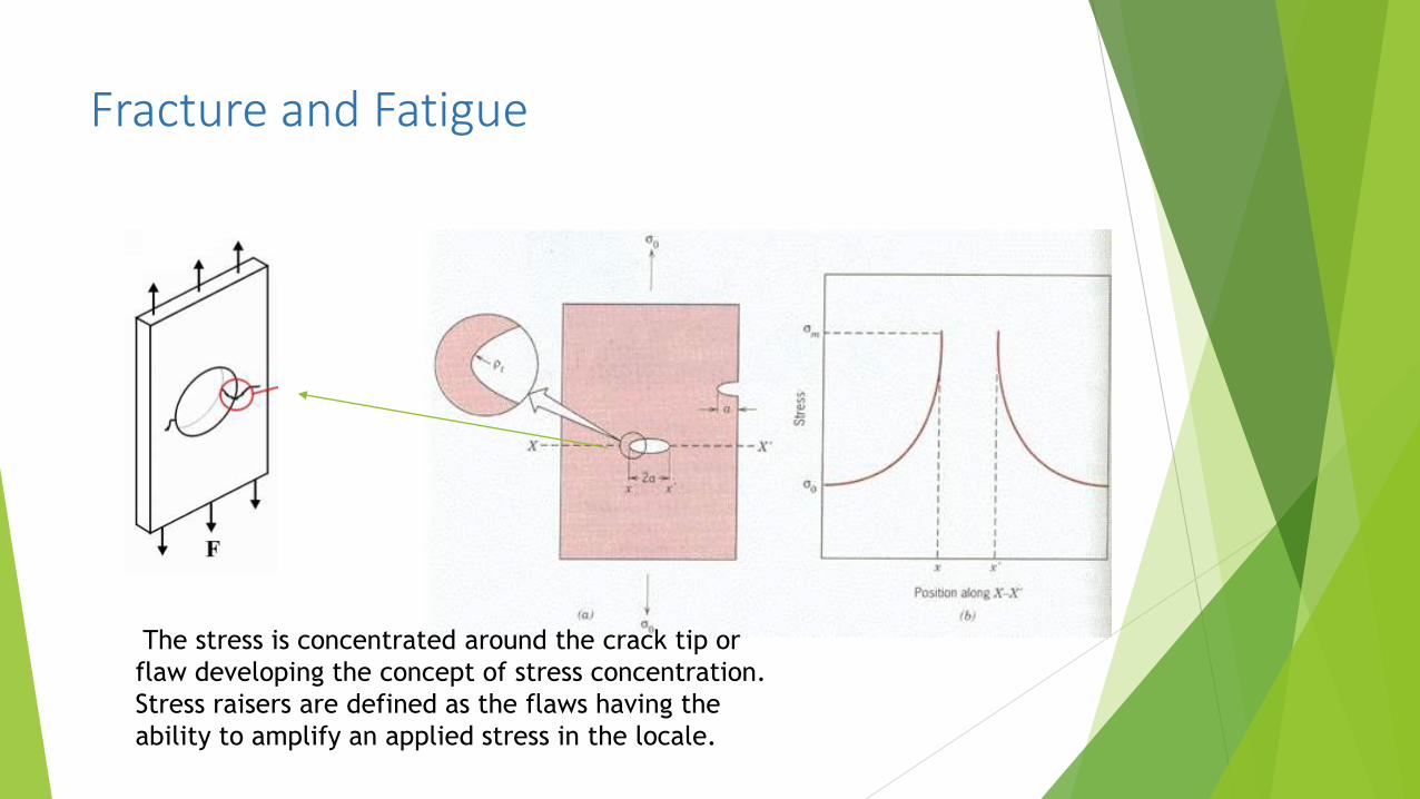
The stress is concentrated around the crack tip or
flaw developing the concept of stress concentration.
Stress raisers are defined as the flaws having the
ability to amplify an applied stress in the locale.

Fracture and Fatigue
A damage tolerant design or ‘safety by inspection’ should allow cracks to be detected before they reach the critical length that will lead to failure.
The damage tolerance approach is based on the principle that while cracks due to fatigue and corrosion will develop in the aircraft structure, the process can be understood and controlled.
To ensure that this occurs there should be at least two opportunities to detect the crack prior to it reaching its critical length
Based on experiment and maths
damage tolerance method may be used but is not mandatory; the safe-life or fail-safe methods may be used instead
The underlying philosophy of damage tolerance design is that damage can, and must, be detected before it becomes critical.
Therefore, scheduled inspections are a central element of the continuing airworthiness processes for a damage tolerance aircraft type.
Fracture and Fatigue
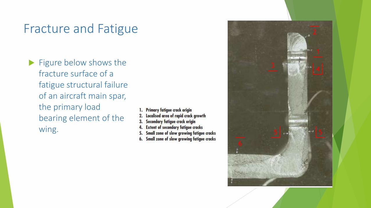
Figure below shows the fracture surface of a fatigue structural failure of an aircraft main spar, the primary load bearing element of the wing.
1
2
3
55
6
4
Fracture and Fatigue
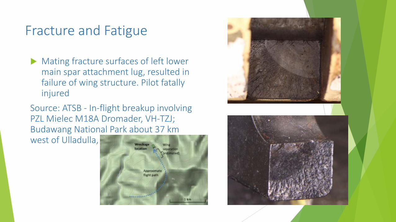
Mating fracture surfaces of left lower main spar attachment lug, resulted in failure of wing structure. Pilot fatally injured
Source: ATSB - In-flight breakup involving PZL Mielec M18A Dromader, VH-TZJ; Budawang National Park about 37 km west of Ulladulla, New South Wales

Fracture and Fatigue
Location of Boeing 767 Body Station 1809.5 bulkhead and wing front spar pitch load fittings
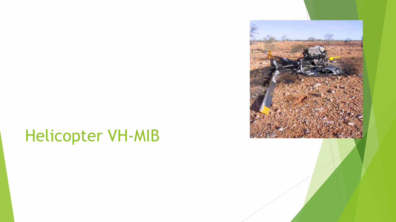
Helicopter VH-MIB

Background
The crew of the Robinson R22 helicopter were undertaking a fence line inspection at about 30 to 40 ft above ground level.
The crew had initiated a turn, a loud bang was heard and the helicopter began to yaw quickly before striking the ground.
Passenger sustained serious injuries. The pilot subsequently died of his injuries.
The flex plate in the forward flexible coupling of the main rotor drive was found fractured at one of the two attachment points to the main rotor gearbox yoke.
The flex plate fractured due to the propagation of a fatiguecrack at one of the bolted connections between the plateand main rotor gearbox yoke.
Do we understand the language? Yes/No?

Legal
Do we understand this language? Yes/No?
Claims based on general law of negligence and a s 74 TPA claim solely against the manufacturer where basically the issue was whether the helicopter and/or the Maintenance Manual had a “defect”, for the purposes of s 75AD and s 75AE of the Trade Practices Act.
In my view a most bizarre outcome (manufacturer lost on appeal), when clearly the engineering was clear on the cause of the crash, as we will see.
The bolted joint was disassembled by a LAME at some time after the manufacture of the helicopter (although that was an inference)
My view of the outcome of the case is that for all flight critical components a maintenance manual must be able to detect a loose bolt irrespective of whether the component had been correctly serviced in accordance with the maintenance manual in the first place.
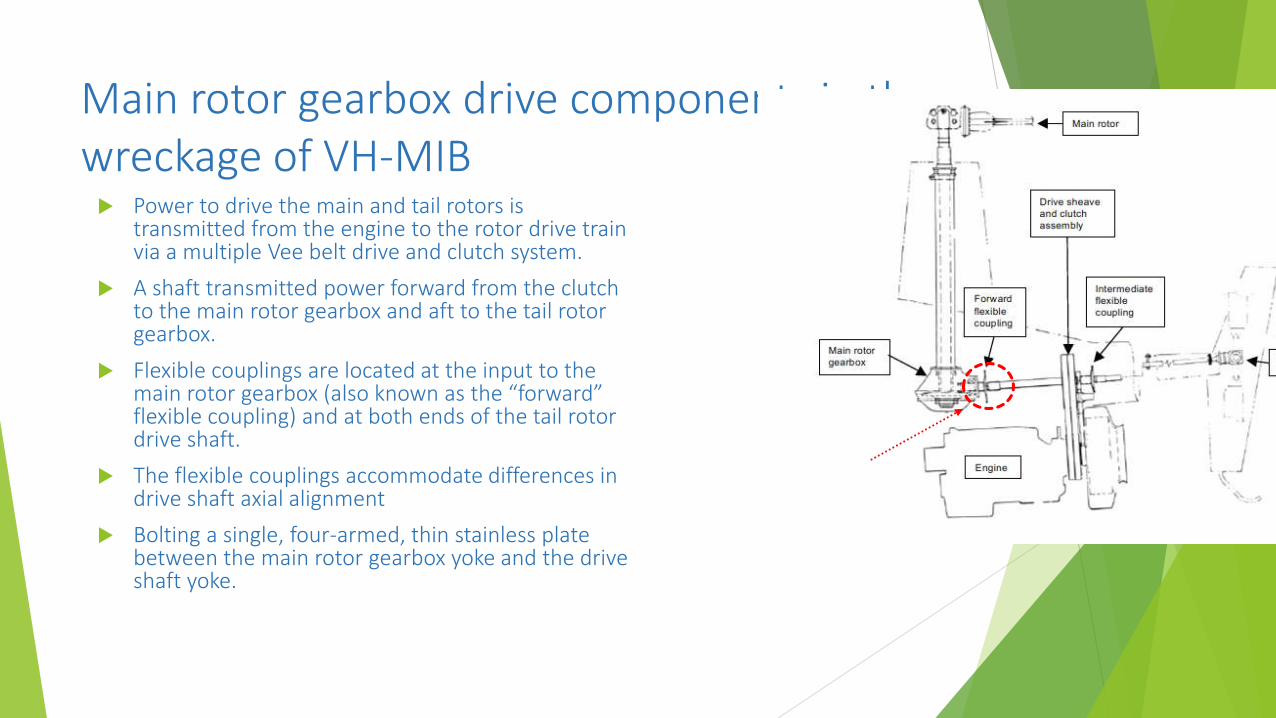
Main rotor gearbox drive components in the wreckage of VH-MIB Power to drive the main and tail rotors is
transmitted from the engine to the rotor drive train via a multiple Vee belt drive and clutch system.
A shaft transmitted power forward from the clutch to the main rotor gearbox and aft to the tail rotor gearbox.
Flexible couplings are located at the input to the main rotor gearbox (also known as the “forward” flexible coupling) and at both ends of the tail rotor drive shaft.
The flexible couplings accommodate differences in drive shaft axial alignment
Bolting a single, four-armed, thin stainless plate between the main rotor gearbox yoke and the drive shaft yoke.

Components of failed forward coupling
(Source: ATSB TRANSPORT SAFETY INVESTIGATION REPORT - Aviation Occurrence Report – 200401917)

Main rotor gearbox drive components in the wreckage of VH-MIB

Components of the forward flexible coupling

Flexplate

Flexplate fracture surfaces
Flexplate (not actual)
2 fracture surfaces (above &
below)
Top crack first to go
Crack directions
Final fracture

Region of final fracture
Final fracture and disconnection from the main rotor gearbox yoke occurred by net section yielding as crack growth from the inner surface of the bolt hole neared the edge of the flexplate arm.
The rate of fatigue crack growth could not be determined with certainty, however, the general features of the fatigue fracture surfaces indicate that crack growth was slow and occurred over the period of more than a few flights.
What do we know so far?
Conclusion: The examination of the main rotor and tail rotor drive components recovered from the helicopter wreckage established that the flexplate in the forward flexible coupling fractured as a result of the propagation of a fatigue crack at one of the bolted connections between the plate and main rotor gearbox yoke.
That’s the analysis so far, but it tells us nothing about who or what actually caused the crash.
Why not?
Answer
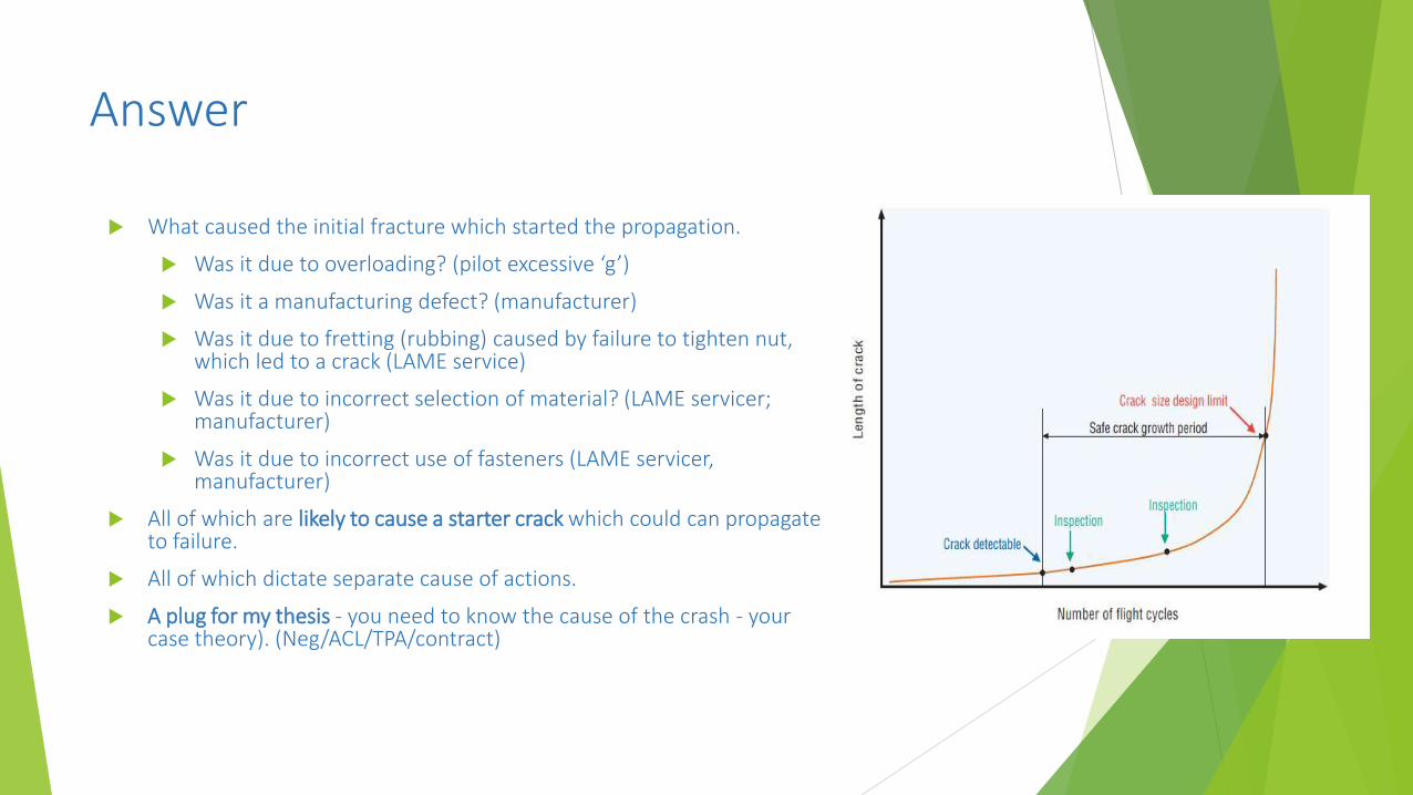
What caused the initial fracture which started the propagation.
Was it due to overloading? (pilot excessive ‘g’)
Was it a manufacturing defect? (manufacturer)
Was it due to fretting (rubbing) caused by failure to tighten nut, which led to a crack (LAME service)
Was it due to incorrect selection of material? (LAME servicer; manufacturer)
Was it due to incorrect use of fasteners (LAME servicer, manufacturer)
All of which are likely to cause a starter crack which could can propagate to failure.
All of which dictate separate cause of actions.
A plug for my thesis - you need to know the cause of the crash - your case theory). (Neg/ACL/TPA/contract)

Bolted joint clamping
The assembly instructions for the flexplate bolted joints require that
each of the four bolted assemblies be tightened 240 in-lb of torque to the nut
the nut is secured by a secondary locking mechanism in the form of a stamped sheet steel nut (Palnut) tightened against the installed nut.
Defined it as a critical fastener
The instructions for assembling critical fasteners included a warning that at least twothreads up to a maximum of four threads must be exposed beyond the end of the nut to allow the proper installation of the locking Palnut.
The warning provides an alert that if more than four threads are exposed the nut may seat against the bolt shank and result in inadequate joint clamping.

Schematic showing the relationship between various joint thicknesses and bolt grip length
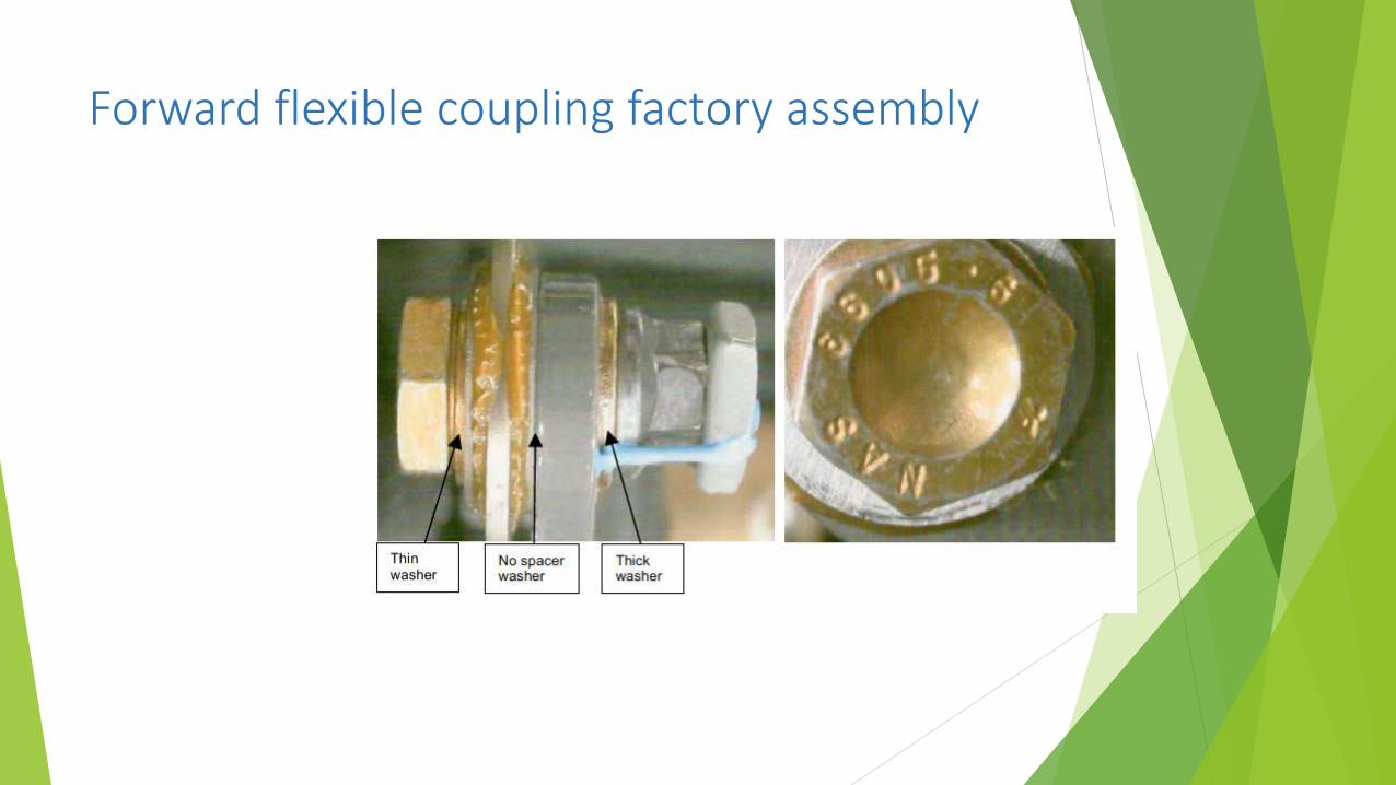
Forward flexible coupling factory assembly

Cause
Initiation and growth of a fatigue crack
Growth to fracture represents a failure of the flexplate fracture
control plan
Evidence of fretting wear. This type and
degree of wear damage is indicative of operation with no clamping force
in the bolted joint.
Looseness at the bolted joint at the flexplate
failure location is due to a mismatch between
joint thickness
Examination of contact marks on the bolt thread
created during nut tightening indicated that the nut, installed on the
bolt at the flexplatefailure location, had not
been advanced any further along the nut
thread than its recovered position (ie so
it wasn’t torques and was in the no more than
4 and no less than 2 thread position.
It was only then a matter of time before the crash happened

Pleaded action at first instance - negligence
McDermott & Ors v Robinson Helicopter Company [2014] QSC 34
That the manufacturer had a duty of care to exercise reasonable care to ensure the Maintenance Manual provided adequate inspection procedures during inspections and servicing:
to detect cracks initiating at the boltholes,
the presence of fatigue cracking in that location,
lack of torque in the bolted joints in the flexplate,
fretting wear of the bolt shaft of the joint connections, and
separation of the bonded washers
In essence what the plaintiff was suggesting was that the defendant had failed to require that the flexplate be verified by removal of the palnuts, re-torquing of the bolted joints, and failed to provide adequate instructions to detect a lack of torque in the bolted joint.
The defendant denied these breaches and pleaded that the Maintenance Manual required provision of torque stripe which would indicate that the bolt had become loose.
The defendant allege that it was unnecessary, undesirable and uneconomical to remove parts including the flexplate at each 100 hour inspection. The plaintiffs denied this.
Pleaded action – TPA
Plantiffs - passenger and his wife - brought a claim for loss under TPA 75AD and s 75AE
Claiming that the goods (helicopter and Maintenance Manual) were defective (ie defective maintenance manual = defective helicopter)
Specifically that the inadequacies of the maintenance manual relating to inspection procedures (in particular the instructions relating to inspection did not convey what is required in sufficiently clear or comprehensive terms), both the helicopter and the maintenance manual were defective, and the defects caused the plaintiffs to suffer loss and damage.
Pleaded action – TPA
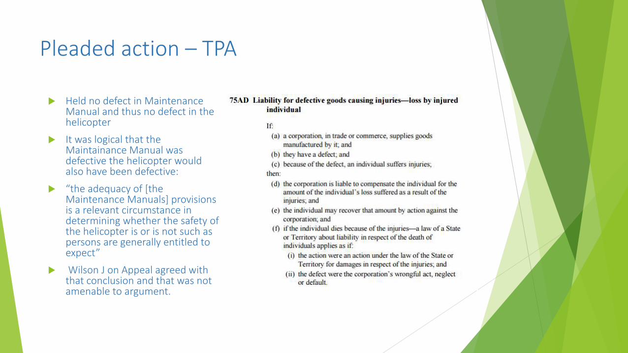
Held no defect in Maintenance Manual and thus no defect in the helicopter
It was logical that the Maintainance Manual was defective the helicopter would also have been defective:
“the adequacy of [the Maintenance Manuals] provisions is a relevant circumstance in determining whether the safety of the helicopter is or is not such as persons are generally entitled to expect”
Wilson J on Appeal agreed with that conclusion and that was not amenable to argument.
Pleaded action – TPA
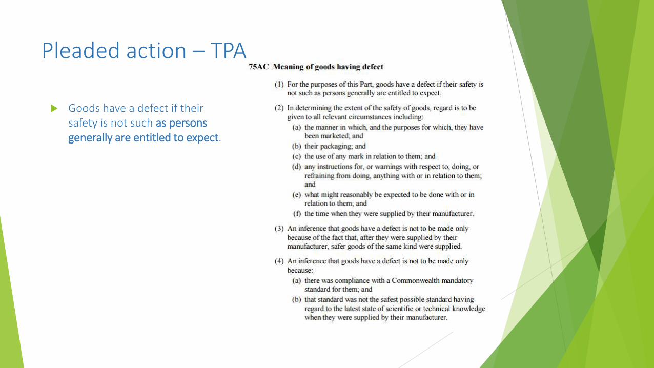
Goods have a defect if their safety is not such as persons generally are entitled to expect.
Test
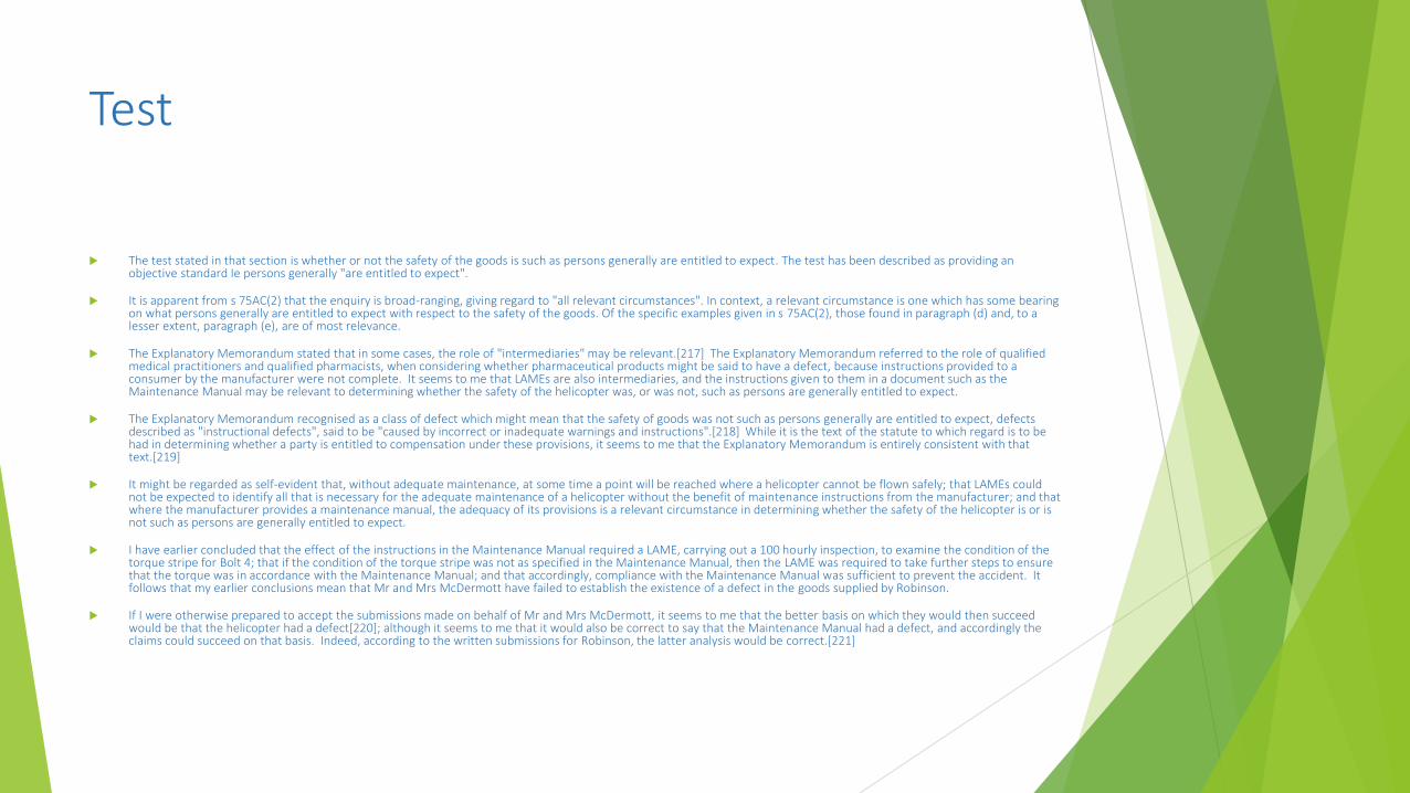
The test stated in that section is whether or not the safety of the goods is such as persons generally are entitled to expect. The test has been described as providing an objective standard Ie persons generally "are entitled to expect".
It is apparent from s 75AC(2) that the enquiry is broad-ranging, giving regard to "all relevant circumstances". In context, a relevant circumstance is one which has some bearing on what persons generally are entitled to expect with respect to the safety of the goods. Of the specific examples given in s 75AC(2), those found in paragraph (d) and, to a lesser extent, paragraph (e), are of most relevance.
The Explanatory Memorandum stated that in some cases, the role of "intermediaries" may be relevant.[217] The Explanatory Memorandum referred to the role of qualified medical practitioners and qualified pharmacists, when considering whether pharmaceutical products might be said to have a defect, because instructions provided to a consumer by the manufacturer were not complete. It seems to me that LAMEs are also intermediaries, and the instructions given to them in a document such as the Maintenance Manual may be relevant to determining whether the safety of the helicopter was, or was not, such as persons are generally entitled to expect.
The Explanatory Memorandum recognised as a class of defect which might mean that the safety of goods was not such as persons generally are entitled to expect, defects described as "instructional defects", said to be "caused by incorrect or inadequate warnings and instructions".[218] While it is the text of the statute to which regard is to be had in determining whether a party is entitled to compensation under these provisions, it seems to me that the Explanatory Memorandum is entirely consistent with that text.[219]
It might be regarded as self-evident that, without adequate maintenance, at some time a point will be reached where a helicopter cannot be flown safely; that LAMEs could not be expected to identify all that is necessary for the adequate maintenance of a helicopter without the benefit of maintenance instructions from the manufacturer; and that where the manufacturer provides a maintenance manual, the adequacy of its provisions is a relevant circumstance in determining whether the safety of the helicopter is or is not such as persons are generally entitled to expect.
I have earlier concluded that the effect of the instructions in the Maintenance Manual required a LAME, carrying out a 100 hourly inspection, to examine the condition of the torque stripe for Bolt 4; that if the condition of the torque stripe was not as specified in the Maintenance Manual, then the LAME was required to take further steps to ensure that the torque was in accordance with the Maintenance Manual; and that accordingly, compliance with the Maintenance Manual was sufficient to prevent the accident. It follows that my earlier conclusions mean that Mr and Mrs McDermott have failed to establish the existence of a defect in the goods supplied by Robinson.
If I were otherwise prepared to accept the submissions made on behalf of Mr and Mrs McDermott, it seems to me that the better basis on which they would then succeed would be that the helicopter had a defect[220]; although it seems to me that it would also be correct to say that the Maintenance Manual had a defect, and accordingly the claims could succeed on that basis. Indeed, according to the written submissions for Robinson, the latter analysis would be correct.[221]
Court of Appeal
Finding that there was no defect in the Maintenance Manual was overturned on appeal in McDermott & Ors v Robinson Helicopter Company Incorporated [2014] QCA 357
Approach adopted: “The case [at trial] focused not upon how the bolt became loose but, rather, why its looseness was not detected.”
Also, consider this statement: “That approach to the question of negligence was plainly, with respect, right. This is a product
liability case against the manufacturer of a helicopter, focusing on its service manual. There was ‘… a risk of catastrophic failure if one of the bolted joints for the flexplate became loose’.[36] The ‘… circumstance that the product is inherently extremely dangerous, or, that the gravity of the risk of injury which negligence creates is serious, only requires that a higher duty of care be exercised…’. [37] In light of the terms of the manual, with its clear wording directed towards checking the security of the bolts, and in light of the way the case was advanced for Robinson, the plaintiffs were not required to prove that the manual failed to address the risk of incompetence or negligence by LAMEs; only, rather, that it failed to adequately address an identified, and accepted, risk – that, for whatever reason, bolts might be loose. Insofar as Robinson appears to advance a different case on appeal, its arguments to that end must be rejected.” at [61] Wilson J
Court of Appeal
Implicitly, isn't the Court of Appeal saying that the actions of the LAMEs in not assembling the bolted connection properly was foreseeable. Is this not setting a very high bar.
For example, what is the extent of the duty. For instance, imagine a situation where no nut was installed on the bolt by the LAME at the 100 hr service interval. The flexplate would propagate to destruction in a matter of hours (certainly under 100 hrs) or even the first flight. Obviously an inspection would be nugatory in that instance. (Note also that the 100 hr inspection interval would more likely be set to identify fatigue crack propagation and not bolt loosening.)
What may be practical outcome- reduced service intervals and di
Arguably at first instance Robinson should have made an attempt to establish negligence on the part of the LAMEs who did not assemble the bolded joint correctly and then establish that this broke the chain of causation.
However the finding of the Court of Appeal – that a Maintenance Manual must be able to identify a lose bolt installed on a flight critical notwithstanding an installation that did not follow the Maintenance Manual in the first place- would not have changed the outcome.