li-fi modulation and networked li-fi attocell · pdf file23 december, 2013 professor harald...
TRANSCRIPT

23 December, 2013
Professor Harald Haas
Li-Fi modulation and networked
Li-Fi attocell concept
Tutorial
TexPoint fonts used in EMF. Read the TexPoint manual before you delete this box.: AAAAAAAA
Contributions by…
Svilen Dimitrov,
Thilo Fath,
Irina Stefan,
Dobroslav Tsonev,
Stefan Videv,
Wasiu Popoola,
Enrique Poves,
Harald Burchardt,
23 December,
2013
2
Sinan Sinanovic
Nikola Serafimovski,
Abdelhamid Younis,
Mostafa Afgani,
Cheng Chen,
Yichen Li,
John Fakidis,

Wireless data is growing
exponentially …
YouTube
In 2011, ~ 140 views for every person on earth (over
1 Trillion views
More video is uploaded to YouTube in one month
than the 3 major US networks created in 60 years
72 hours of video are uploaded to YouTube every
minute
25% of global YouTube views come from mobile
devices Source - http://www.youtube.com/t/press_statistics
Internet video traffic is growing at 48% CAGR Source - Cisco Visual Networking Index: Forecast and Methodology, 2010-2015
23 December,
2013
3
23 December,
2013
4
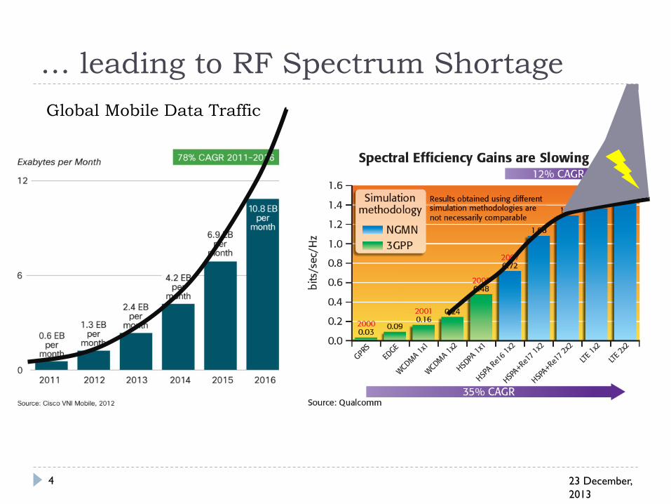
… leading to RF Spectrum Shortage
Global Mobile Data Traffic

How fix the problem?
1. Identify new spectrum, and/or
2. Enhance spectrum reuse
(smaller cells)
23 December,
2013
5

The electromagnetic spectrum
23 December,
2013
6
.
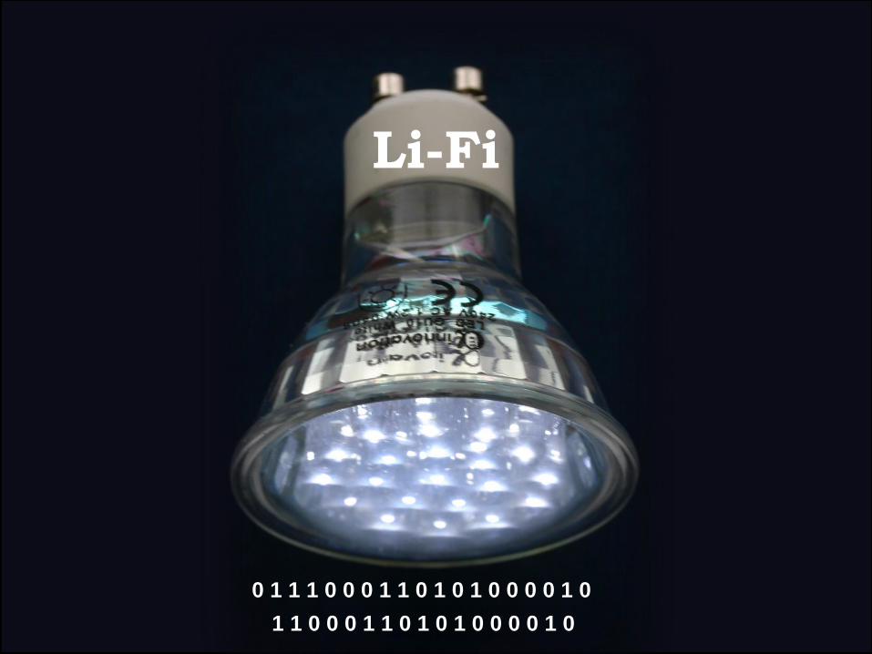
0 1 1 1 0 0 0 1 1 0 1 0 1 0 0 0 0 1 0
1 1 0 0 0 1 1 0 1 0 1 0 0 0 0 1 0
Li-Fi
23 December,
2013
8
Optical Attocell Concept
23 December,
2013
9
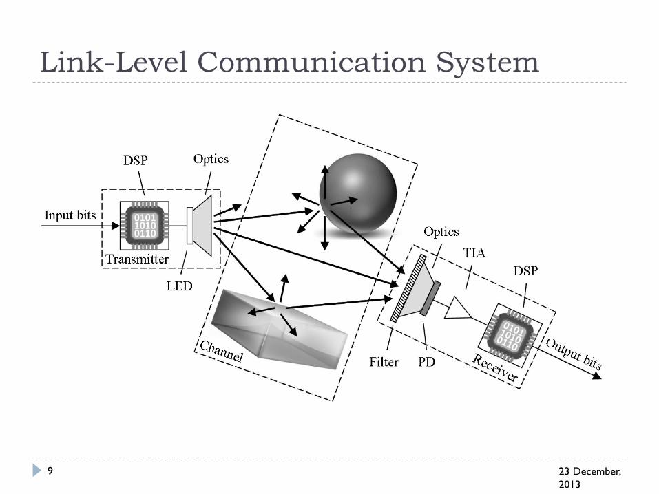
Link-Level Communication System

23 December,
2013
12
Communication Scenarios

State-of-the-Art: Wi-Fi
23 December,
2013
13
Wi-Fi Router Location

State-of-the-Art: Wi-Fi
23 December,
2013
14
Wi-Fi Router Location
23 December,
2013
15
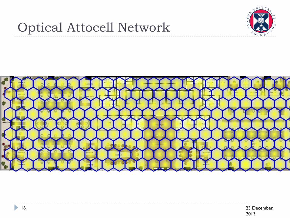
Optical Attocell Network
23 December,
2013
16

Data rates per device
23 December,
2013
17
Space per desk 4 m2
100 employees per
floor
Assume a uniform
distribution of
employees
20m x 20m floor = 400
m2
Area can be covered
by a single Wi-Fi AP
Each Li-Fi AP can
cover around 4 m2
Wi-Fi data rate 600
Mbps
Li-Fi data rate 20 Mbps

Interference Scenario
23 December,
2013
20
user, k
desired signal
I. Stefan, et al., VTC 2013-Spring, 2013

Optimisation Framework
23 December,
2013
21

Rx FOV 85° - without lighting
constraint
23 December,
2013
22

Rx FOV 85° - with lighting
constraint
23 December,
2013
23

Rx FOV 45° - without lighting
constraint
23 December,
2013
24

Rx FOV 45° - with lighting
constraint
23 December,
2013
25

23 December,
2013
26
23 December,
2013
27
Digital Modulation

December 23,
2013
28
Key differences to RF
System
RF
Incoherent
Optical
Information
carried on
electric field
carried on
optical intensity
Signal
bipolar
unipolar
non-negative
complex
valued
real
valued
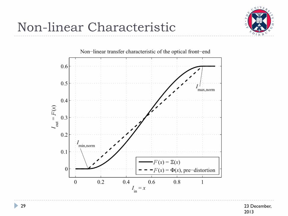
Non-linear Characteristic
23 December,
2013
29
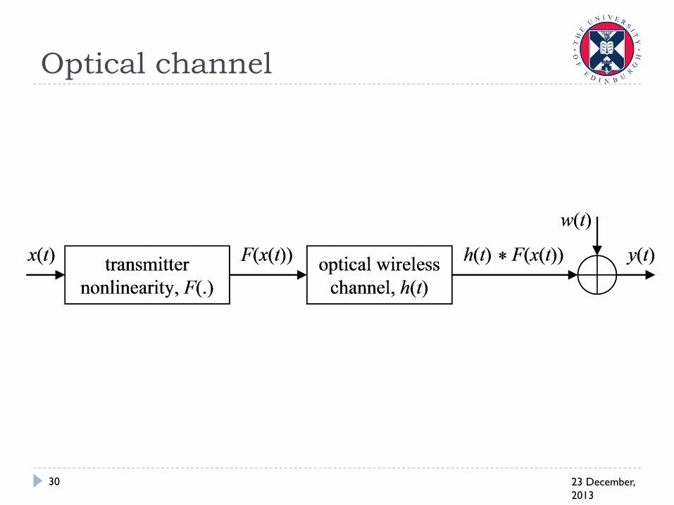
Optical channel
23 December,
2013
30

Coherence Bandwidth of Channel
23 December,
2013
31

Path loss
23 December,
2013
32
bi-directional reflectance
distribution function
(BRDF)

Path loss, cont’d
23 December,
2013
33
Optical path gain
Electrical path gain
Path loss
Irradiance
distance Detector area
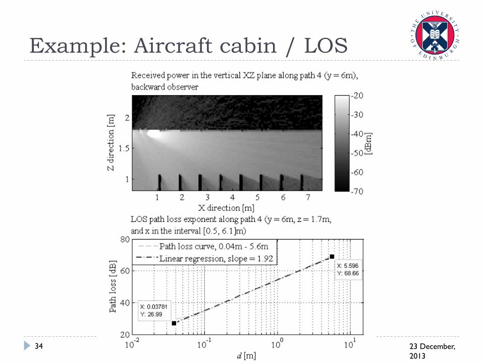
Example: Aircraft cabin / LOS
23 December,
2013
34

Example: Aircraft cabin / NLOS
23 December,
2013
35

23 December,
2013
36
Modulation Techniques
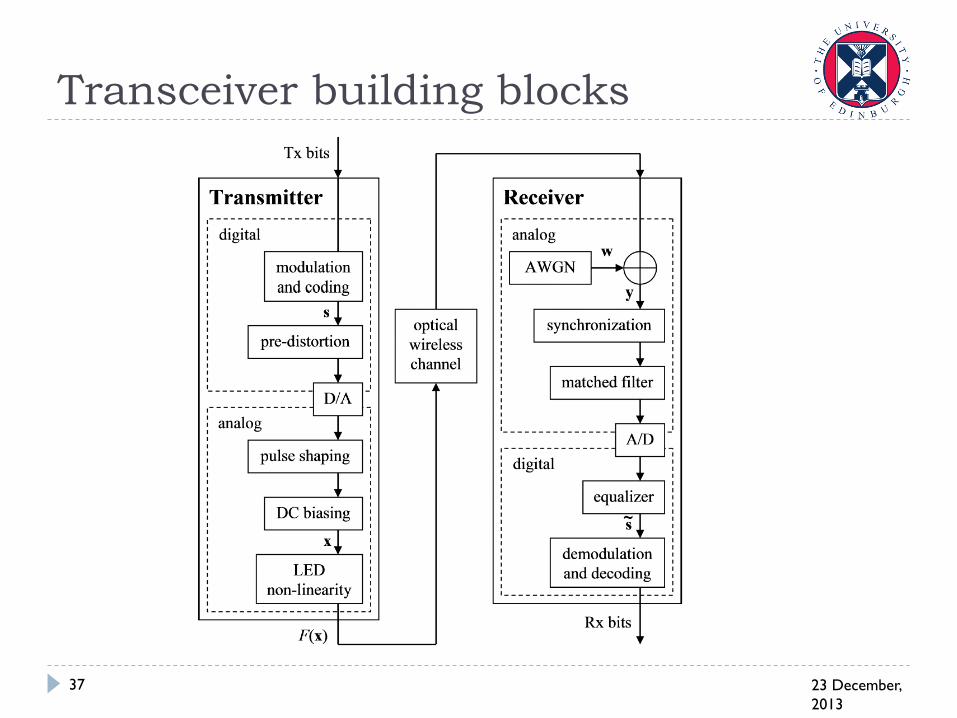
Transceiver building blocks
23 December,
2013
37

Pulsed Modulation
On-OFF Keying
December 23,
2013
38
Time
Intensity
1 1 1 1 0 0 0 0 0
On
Off
Thres.
Finite slope limits
achievable data
rates

Single Carrier Binary
23 December,
2013
39

Single Carrier Multi-level
23 December,
2013
40

PPM: BER Performance
23 December,
2013
41
Spectal Efficiency:

PAM: BER performance
23 December,
2013
42
Spectal Efficiency:

December 23,
2013
43
OFDM-based OWC System
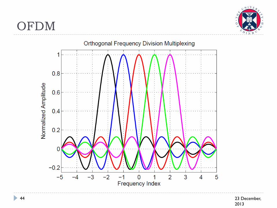
OFDM
23 December,
2013
44

DCO-OFDM and ACO-OFDM Symbol
Structures
23 December,
2013
45
DCO-OFDM
ACO-OFDM
𝑥𝑁2−1
𝑥𝑁2 𝑥∗1
𝑥∗𝑁2−1
𝑥𝑁2−1
𝑥𝑁2
𝑥∗𝑁2−1
𝑥∗1
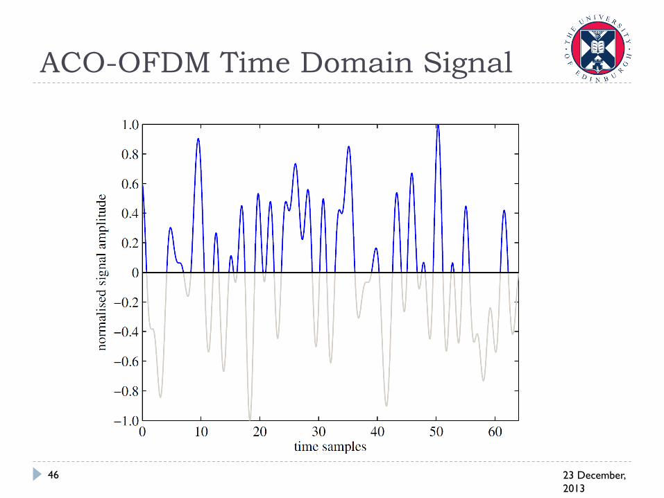
ACO-OFDM Time Domain Signal
23 December,
2013
46
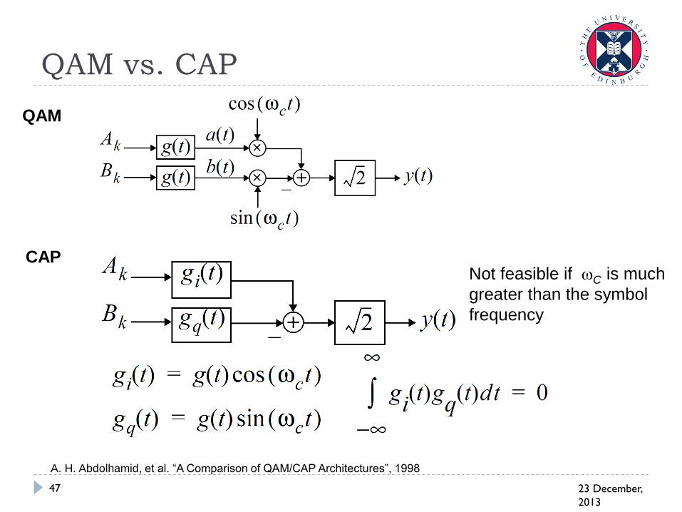
QAM vs. CAP
23 December,
2013
47
Not feasible if C is much
greater than the symbol
frequency
QAM
CAP
A. H. Abdolhamid, et al. “A Comparison of QAM/CAP Architectures”, 1998

December 23,
2013
48
OFDM Generation (Time Domain)
After the IFFT, the signal follows a zero-mean Gaussian
distribution in the time domain:
Probability density
function Time-domain signal
-6 -4 -2 0 2 4 6-6
-4
-2
0
2
4
6
Quadra
ture
In-Phase
Scatter plot
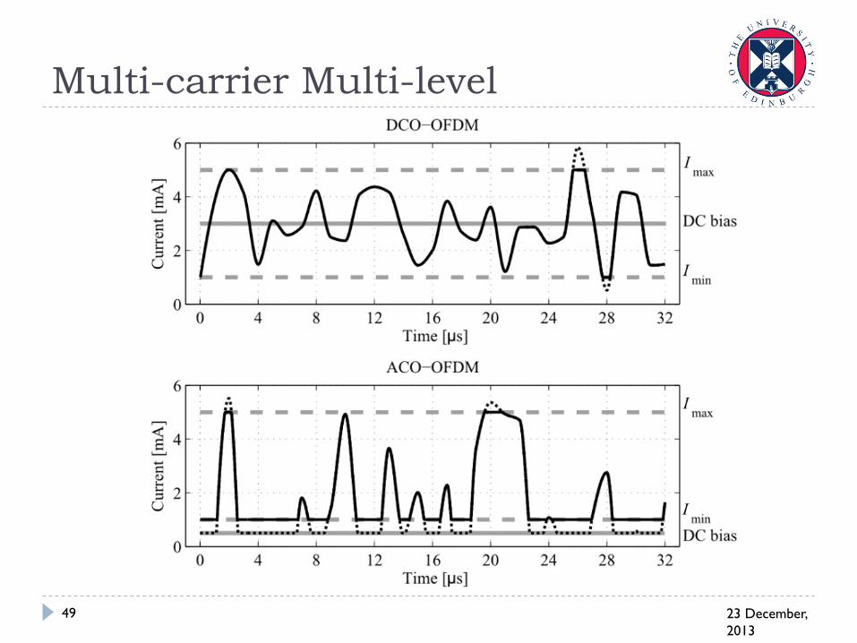
Multi-carrier Multi-level
23 December,
2013
49
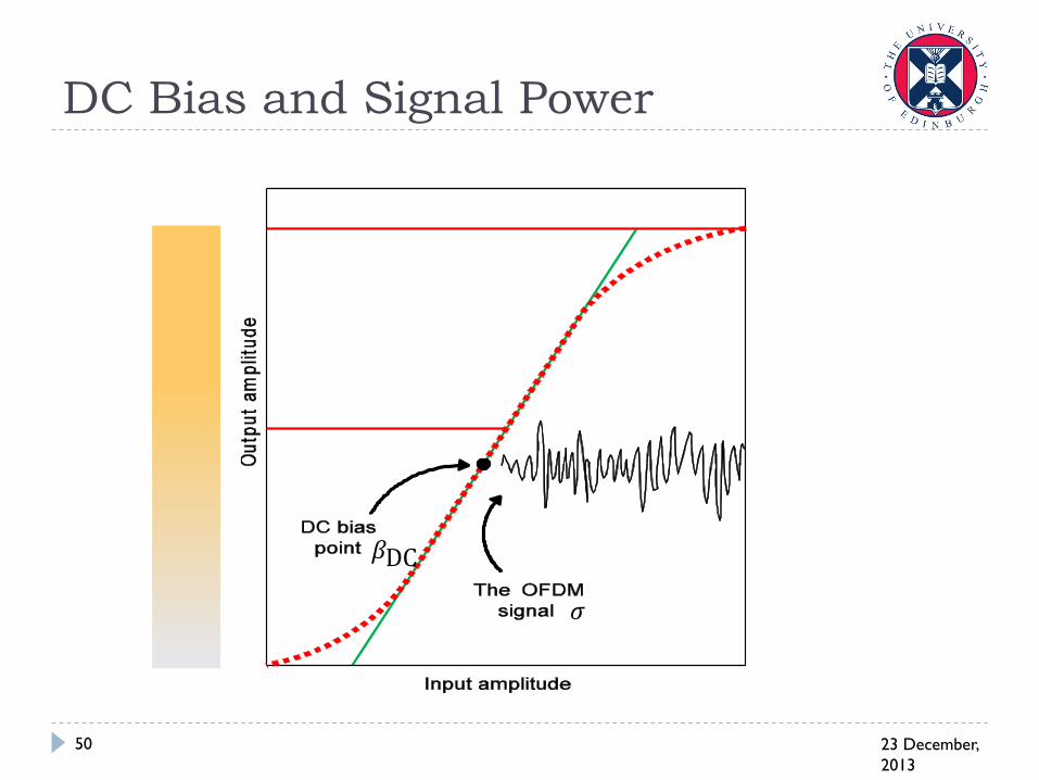
DC Bias and Signal Power
23 December,
2013
50
𝛽DC
𝜎
23 December,
2013
51
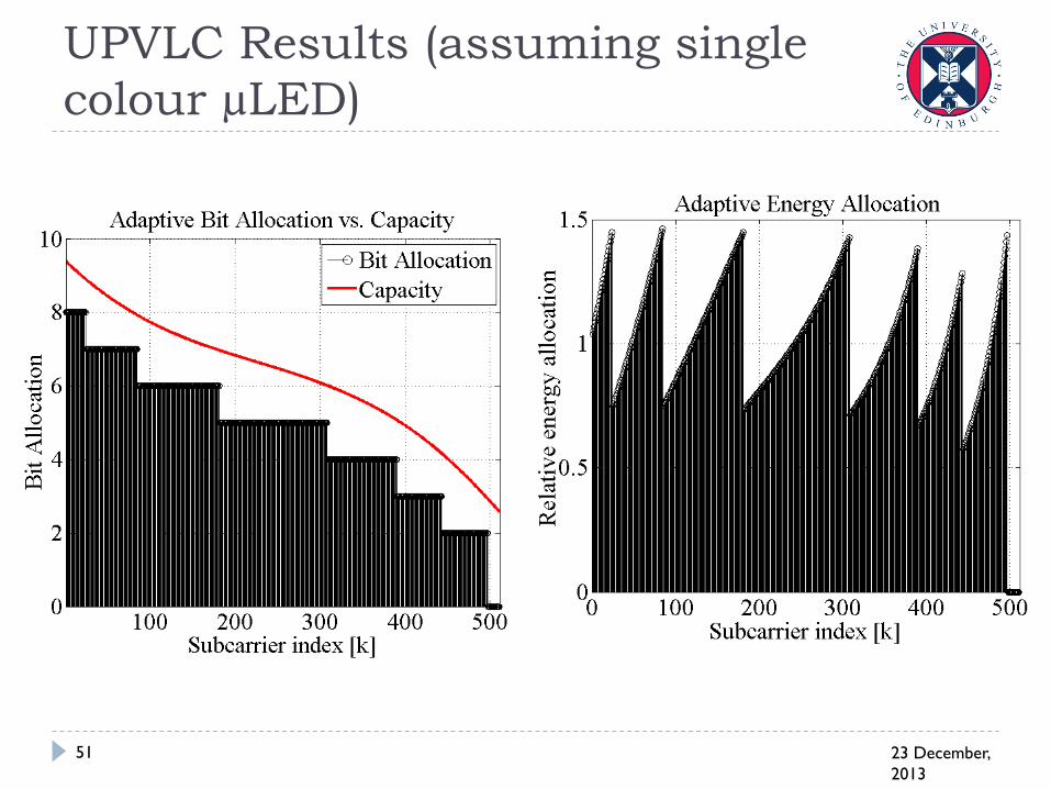
UPVLC Results (assuming single
colour µLED)

December 23,
2013
52
Bussgang Theorem
X is a zero-mean Gaussian random variable with variance σ
and g(X) is an arbitrary transform on X, which could be
linear or nonlinear.
The Bussgang theorem:
Then:
2n
2
nn
n
2222
n
2
EEVar
gEE
gEE
gE
YYY
XY
KXY
XXK
0E
g
n
n
XY
YKXX
no
old
b
2
new
o
new
b
Var YN
EK
N
E
December 23,
2013
53
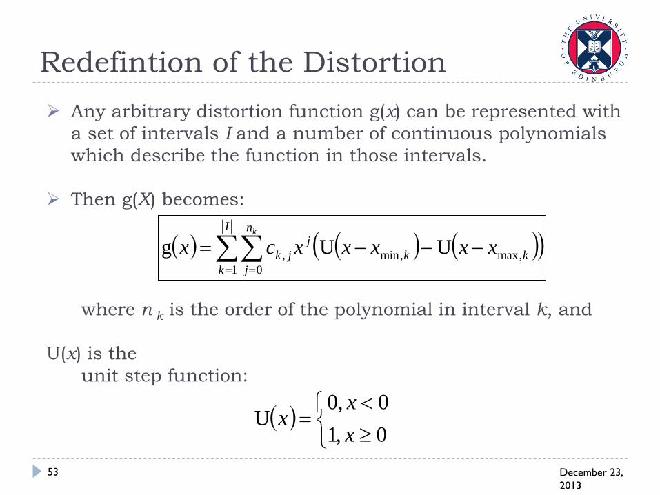
Redefintion of the Distortion
Any arbitrary distortion function g(x) can be represented with
a set of intervals I and a number of continuous polynomials
which describe the function in those intervals.
Then g(X) becomes:
where n k is the order of the polynomial in interval k, and
U(x) is the
unit step function:
I
k
n
j
kk
j
jk
k
xxxxxcx1 0
,max,min, UUg
0,1
0,0U
x
xx

December 23,
2013
54
Examples
3-bit DAC:
Clipping and LED
current-to-light
conversion:
5.1UU3
U5.1U1
5.1UU1
U5.1U3g
xx
xx
xx
xxx
1UU1
3U1U571
U3U3g
2
xx
xxxx
xxx
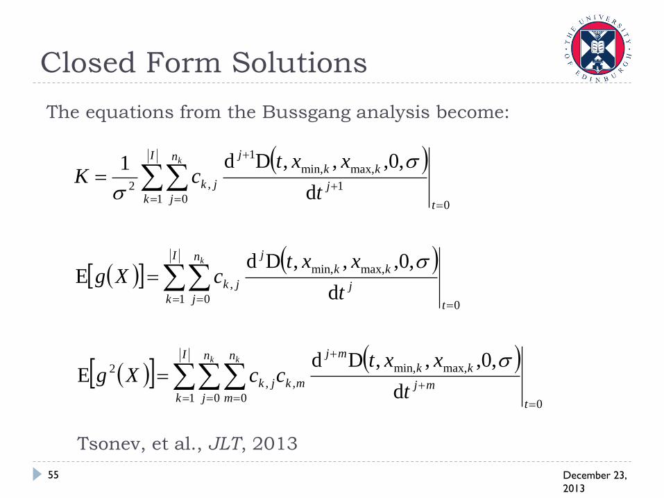
The equations from the Bussgang analysis become:
December 23,
2013
55
Closed Form Solutions
I
k
n
jt
j
kk
j
jk
k
t
xxtcK
1 00
1
max,min,
1
,2 d
,0,,,Dd1
I
k
n
jt
j
kk
j
jk
k
t
xxtcXg
1 00
max,min,
,d
,0,,,DdE
I
k
n
jt
n
mmj
kk
mj
mkjk
k k
t
xxtccXg
1 00
0
max,min,
,,
2
d
,0,,,DdE
Tsonev, et al., JLT, 2013

Channel Capacity: Optimisation
Frameworks
23 December,
2013
56

Results
23 December,
2013
57
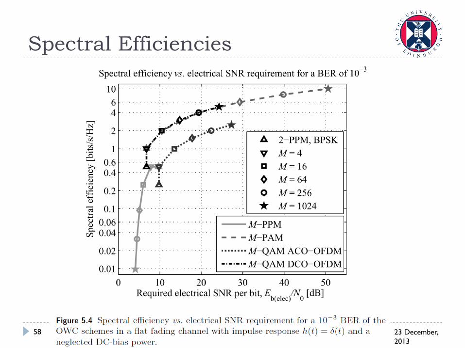
Spectral Efficiencies
23 December,
2013
58
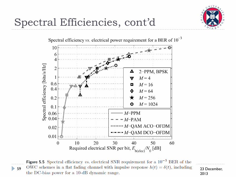
Spectral Efficiencies, cont’d
23 December,
2013
59

Implications on Dimming
23 December,
2013
60

Optical Output Power
23 December,
2013
62

Spectral Efficiency of OFDM
23 December,
2013
63
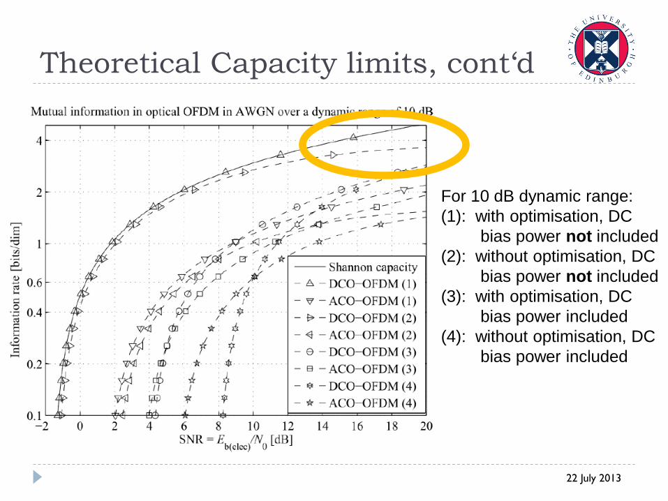
Theoretical Capacity limits, cont‘d
22 July 2013
For 10 dB dynamic range:
(1): with optimisation, DC
bias power not included
(2): without optimisation, DC
bias power not included
(3): with optimisation, DC
bias power included
(4): without optimisation, DC
bias power included

Spatial Modulation: How does it
work?
12/23/2013 66
00(00)
01(00)
10(00)
11(00)
00(11)
01(11)
10(11)
11(11)
00 (Tx0)
01 (Tx1)
10 (Tx2)
11 (Tx3)
Signal Constellation
Spatial Constellation
Re
Im
Im
Im
Re
Re
© The University of Edinburgh
Spectral Efficiency:

Spatial Modulation OFDM
23 December,
2013
67

23 December,
2013
68
Thank You!