:l,;;~gardenlsland dockyard, i ing ~9
TRANSCRIPT

'Goddell Mackay LoganHeritage Consultants
~l)dden Mackay Logan Pt, Ltd (AC. 001 119362) 78 George Street RedferU,Sydn
:l,;;~Gardenlsland Dockyard, i ing ~9~):rl1e Hydraulic Hoists, Remains of the Hydraulic Lift Systel11"and~ . ./:Electric Lift System in Building 89 Garden Islpnd Dockyard
)R~p)&rt prepared by Godden & Associates for Department of Housing and Constructions
1885->,«-
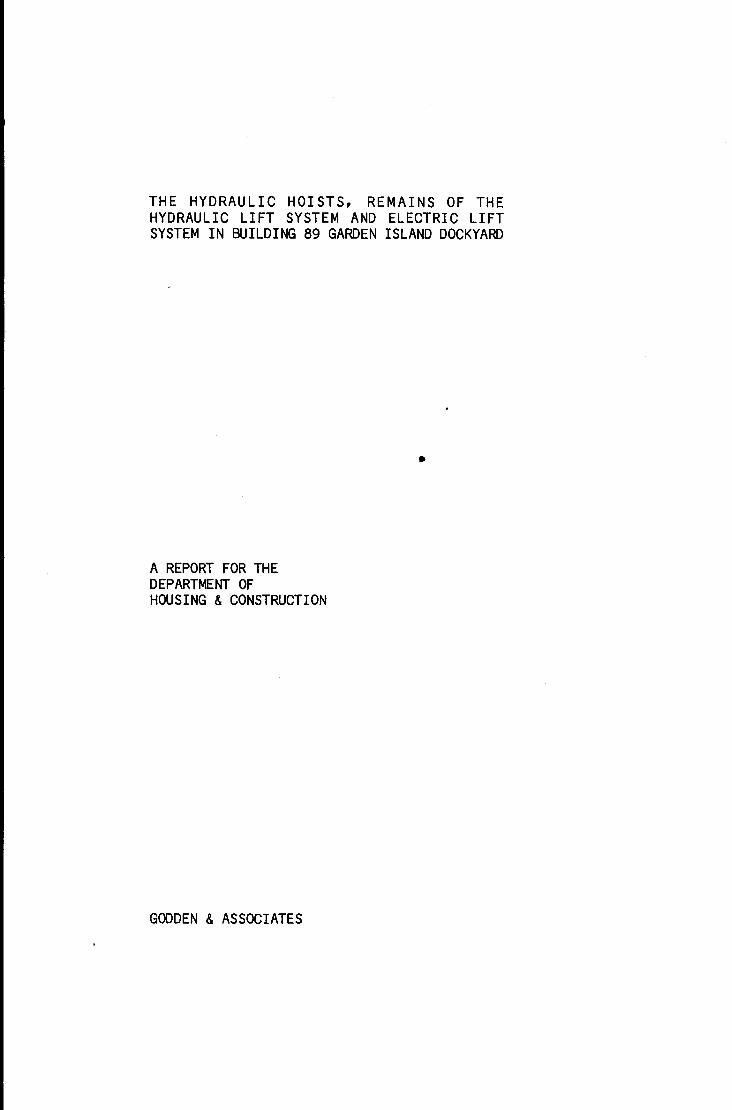
THE HYDRAULIC HOISTS, REMAINS OF THEHYDRAULIC LIFT SYSTEM AND ELECTRIC LIFTSYSTEM IN BUILDING 89 GARDEN ISLAND DOCKYARD
•
A REPORT FOR THEDEPARTMENT OFHOUSING &CONSTRUCTION
GODDEN &ASSOCIATES
THE HYDRAULIC HOISTS.. REMAINS OF THEHYDRAULIC LIFT SYSTEM AN) ELECTRIC LIFT
SYSTEM IN IlJILDIt«2 89.. GARDEN ISlAN) DOCKYARD
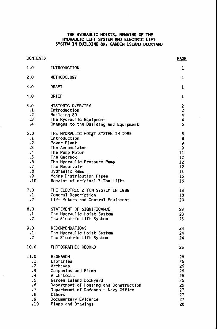
CONTENTS E&1E.
1.0 INTRODUCTION 1
2.0 METHODOLOGY 1
3.0 DRAFT 1
4.0 BRIEF 1
5.0 HISTORIC OVERVIEW 2.1 Introduction 2.2 Building 89 4.3 The Hydraulic Equipment 4.4 Changes to the Building and Equipment 6
6.0 THE HYDRAULIC HOIiT SYSTEM IN 1985 8.1 Introduction 8.2 Power Plant 9.3 The Accumulator 9.4 The Pump Motor 11.5 The Gearbox 12.6 The Hydraulic Pressure Pump 12.7 The Reservoi r 12.8 Hydraulic Rams 14.9 Mains Distribution Pipes 16.10 Remains of original 3 Ton Lifts 16
7.0 THE ELECTRIC 2 TON SYSTEM IN 1985 18.1 General Description 18.2 Lift Motors and Control Equipment 20
8.0 STATEMENT OF SIGNIFICANCE 23.1 The Hydraulic Hoist System 23.2 The Electric Lift System 23
9.0 RECOMMENDATIONS 24.1 The Hydraulic Hoist System 24.2 The Electric Lift System 24
10.0 PHOTOGRAPHIC RECORD 25
11.0 RESEARCH 26.1 Libraries 26.2 Archives 26.3 Companies and Firms 26.4 Architects 26.5 Garden Islahd Dockyard 26.6 Department of Housing and Construction 26.7 Department of Defence - Navy Office 27.8 Others 27.9 Documentary Evidence 27.10 Plans and DraWings 28

1.0 INTRODUCTION
ScopeThis report concerns only the hydraulichoist system, the remains of the hydrauliclift system and the electric lift systemcontained within building 89. It does notcover any of the cranes, loading aprons, orother external equipment associated with thehoist system.
2.0 METHODOLOGYThe work was carried out in accordance withthe guidelines set out in The ConservationPlan, by Jim Kerr, published by the NationalTrust of Australia (NSW) 1982.
3.0 DRAfTA draft of th i s report was subm itted to theDepartment of Housing and Construction forcomment on August 6, 1984.
Consultant Brief for investigation ofhistoric background and contents of Building89, HMA Nayal Dockyard, Garden Island
4.0 BRIEF
.1 To investigate and report on the history andcondition of all equipment, artifacts andstructures contained within Building 89 onGarden Isl and, Sydney in el aboration ofreport prepared by Gordon Forbes Smith (May1985) •
•2 To recommend what would constitute aphotographic record of all equipment,artifacts and structures contained withinBuilding 89 and to take any necessaryphotographs as agreed with the Department•
•3 To write a statement of significance of allsuch equipment and to propose a series ofrecommendations detailing how this equipmentshould be treated in any future re-use ofthe building. Where the projected re-useand the recommendations for treatment are atvariance, then Godden and Associates willsuppl y a range of options.
1

5.0 HISTORIC OVERVIew
.1 IntroductionAt the end of the nineteenth century, beforeel ectric motors were perfected, theprincipal sources of power for industry andcommerce were steam and hydrau 1 ic pressure.A pub 1 ic system of high pressure hydraul icpower was introduced to Sydney in 1891.Before that, however, several privatesystems were operating hoists and lifts.
The Sydney Hydraulic Power Supply Cocommenced reticulation of high pressurewater power from the Pier St Ultimo pumpingstation in January 1891. By June 1894 overtwo hundred machines, mainly whips (orhoists) and 1 ifts, were being suppl ied andthis number grew steadily until after thefirst world war. In 1894 there were 18 kmof mains. One main ran from Pier St downSussex St to Millers Point, while others ranalong Market St and then down George St andPitt St.
There were direct acting passenger lifts inthe Austra 1 i a Hotel, the Government Landsand Works Offices, the Mutual LifeAssociation and the old Anthony Hordens andSons building. Many smaller buildings hadgoods lifts or passenger lifts powered byhydrau 1 i c rams, many more had i nterna 1 andexternal hoists, while many of the wooldumps of Walsh Bay and Pyrmont wereconnected to the system.
With the gradual expansion of services twobooster stat ions were added to the system,one at Cowper Wharf Road Wool loomooloo andone at Pyrmont. The hydraul ic system wasnot as versatile, economic nor as convenientas electric power and the Company graduallylost customers from the 1930s on. The PierSt pumping station was finally closed in1975. Some of the buildings which werestill connected to the service at that timechose to install individual electrichydraulic pumps to power their lifts andhoists rather than change to a compl etel ynew all electric system. However thesesystems now use oi 1 as the hydraul ic fl uidand do not have accumulators. In July 1985there were only a few of these connectedsystems still in operation.
2
T. Dlcklnson,ill_hsl.ll·":'.':&Y...., u1~O~t~h~MU.ay..lJ,,~1~8~9""4l.IL,IlJlIProceedfngs 9, The EnglneerlAssocIation of N.S.W., 1893-94.

There are still several relics remainingfrom the hydraulic power company. The PierSt pumping station building survives withoutany of its machinery. Parburys Old BondStore in Windmi 11 St, The Rocks, has threedirect acting 1ifts in situ, while OswaldsBond in Kent St has four external hydraulicgoods lifts, of advanced design, and oneexternal hydraul ic hoist. Other buildingssuch as Moors Bond, at Walsh Bay, and theMetcalfe Bond at Circular Quay have theexternal hydraulic ram and hoist apparatusaff ixed to thei r facade, but rather asdecoration.
There are still several operating hydraulicsystems in Sydney but all have industrialrather than commercial or service uses.Cockatoo Island has a high pressure Ruwalttriplex pump supplying an accumulatorsituated in the ma i n workshop. The SRA hastwo accumulators which supply power toseveral machines in the carriage workshopsand the locomotive workshops at Eveleighworkshops. At Wal sh Bay, wharves 8 and 9,there is a large duplex pump driven by a 65HP electric motor, a massive brick ballastaccumulator which served two internal hoistsand a passenger-goods lift. This system isinoperabl e and the accumul ator is in aderelict condition.
Garden Isl and al so has a hydraul ic systemwhich powers a flange press in the boilershop.
There are no complete hydraulic systemsoperating external hoists in Sydney besidesthe one on Garden Island.
The advent of hydraul ic power, which couldbe used safely and conveniently to raise andlower goods and people, meant thatcommercial or stores buildings could beincreased in height from two to four or fivestoreys.
Hydraul ic power was used on Garden Isl andfrom 1894 to operate lifts and hoists in the4 storey Victualling stores, now known asbuilding 89. These hoists have not beenused since 1980. Another hydraul ic system,completely separate, is still being used topower the flange press in building 104.
3

.2
.3
.3.1
Building 89The contract for the foundations was let toP. O'Rou rke and W. Roper on 11th August1891. The building was completed by HowieBrothers in 1894.
The hydraulic eQuipmentTenders for the supply and installation offive 15 cwt (.7St) hyd rau 1 i c ho i sts and two60 cwt (3t) hydraul ic lifts, pump,accumulator and associated fittings werecal led in 1893. Those who submitted tenderswereAtl as Engi neering Ltd, Wool wich,R Waygood and Co, England,Parke and Lacy, Engineers and Machinery
Merchants, Sydney,H Vale and Sons, Engineers, Auburn N.S.W.,Brown Bros and Co for J Aldridge and
Sinclair,Morts Dock and Engineering Co, Balmain.
N,S,Wo Government Gazettes: In E.J. Mart- Garden Island Building ConservatlStudy - Thesis for M.B.Env., UNSw, 198
NoS,Wo Goyernment Gazettes: In E.J. Mart- Garden Is1 and Bull dlng ConservatlStudy - Thesis for M.B.Env., UNSW, 198
Tender Documents he1 d by Garden Is1 aDockyard Drawing Office CCompactus AlSection 8 Top Shelf).
The contract, wh i ch was 1 et to Morts Dockand Engineering Co on 22nd August 1893, wasfor the hydraulic equipment only. Thefoundations and pi pi ng were to be completed NoS.Wo GQurnment Gazettes, op.clt.by the Garden Island Staff. Martin •
•3.2 Tender ModificationsThe building was well advanced when tendersfor the hoists and lift were finally called.The draw i ngs for the tender showed thehydraul ic rams for the five hoists passingthrough the floor of level 4. This meantthat the rams would have had to have tripleshea ves at each end to enab 1 e the 1 i ftdistance to be achieved. The tender byMorts Dock, which was accepted, used a twinsheave system and the level 3 floor had tobe penetrated to accommodate the rams.
This meant that the doors on level 2 now hadto be modified to avoid the ram cyl inder.The sliding doors on level 3 and level 4were made as single units to be opened byro 11 i ng them to the side oppos ite the ram.The doors on 1evel 1 and 1evel 2 were madein two halves and were opened by sliding thehalves apart. When the rams penetrated thefloor of level 3 the two halves of the doorswere joined and the roll ing rail wasattached to the wall so these doors alsooperated by rol ling to the side opposite theram.
4
Tender DocumentA held by Garden IslaDockyard Drawing Office CCompactus AlSection 8 Top Shelf).
Comparison of Tender Documents and exlstlBuilding Fabric.

.3.3 Location of the pump and accumulatorIt would appear that the Naval Stationwanted the pump and accumulator situatednear the dynamo room and boiler house whichabutted bu1l ding 95. The pump woul d havealmost certainly have been driven by steamand it is likely that it would have beenplaced close to the bo il ers. Theaccumulator needed room to operate and it isprobable that it was located in or close tothe same bu1lding. The hydraulic pipeswould have been run underground to building89.
Various tenderers proposed differentpos it ions for the accumu 1ator and pumpexcept Morts Dock and Engineering which didnot appear to have specified a location•
•3.4 The Goods TramwayInitially there was a fairly extensivetramway for moving goods and equipmentaround the Naval Station. A double tramtrack ran in front of building 89. Thetrack closest to the building was equippedwith turntables in front of doors 2 and 4wh 1ch li nked with tracks that 1ed di rectl yto the 3 ton lifts. The tracks with i n thebu1l ding are still insitu.
5
Plan: "Na va1 Stat ion - Ga rden I s land, Na va 1and Victuall ing Stores - Plan Shewing(sic) Position of Hoisting Machinery"(6.4.93) PWD Neg.No. 4461 (FA92B39) held in G.I.D. Drawing Office.
Plan: "Naval Station - Garden Island, Navaand Victuall ing Stores - Pl an Shewin(sic) Position of Hoisting Machinery(6.4.93) PWD Neg.No. 4461 (FA92B39)held in G.I.D. Drawing Office.
Figure 1. Level 2, bay S. The hydraul ic ramis attached directl y to the wall on thislevel. The twin control cable passes infront of the ram and then th rough two sma 11holes in the floor. The door on this levelwas originally in two halves but these werelater joined together to form a single doorwh fch opens to the right (oppos ite the ram).The roller rail, above the door, was movedone metre to the right to accommodate thenew door.

Th is system a 11 owed goods to be ra i seddirectly from the trucks by use of thehoists, or alternatively the trucks could bewheeled into the building and the goodstransferred to the 1 i fts. There was a 3 rdturntable, where the tracks converged at theeastern end of the building, which allowedswitching from one track to another•
•3.5 The three ton liftsThe 3 ton 1 i fts had open cages 2.1 m0') by1.7 m(S'6") which ran on two guide rails.They were powered by twin sheave horizontalhydraul ic rams which had 200 mm (8")diameter pi stons.
The 1 i ft well was open except for acontinuous post (several lengths scarfedtogether) at each corner, and fixedbalustrading 3.1 m (3'6") high on two sidesand hinged gates front and back to al lowaccess to the cage.
The rams were mounted horizontal 1y N-S onbeams fixed to a simple RSJ frame which wasmounted on four cast iron columns andattached to the north wall. These fourcolumns were identical to those on the floorbelow, and as they have no floor to supportthere are only 8 of them on level 4.
The rams were twin sheaved, indicating asi mi 1 a r stroke 1ength to the 15 cwt ho i stsand the doubling of the ram diameter gavefour times the lifting power•
Plan: "Garden Is1 and Naval Storehou$(25.4.44). Comm. of Aust•• Dept. of tInterfor. Works and Services BranDrawfng No. NoS.W. DEF.38177. (FM5Tl- held fn G.I.D. Drawing Offfce.
Plan: "Naval ·Statfon - Garden Island. Navand Vfctua1 1fng Stores - Detail of Gaand Raf 1 fngs to LHt Well Opening(undated). Drawfng No. 3.759J fn G.IDrawfng Offfce.
Ibfd. Tender Documents.
. 4 Changes to the building and equipmentThe initial function of building 89 was asvictualling s\ores for the Navy. In 1913with the REVY constructions and theprovision of water access at Pyrmont itbecame a general naval store.
There appears to have been a major refit inthe 1930s. The chimney for the boiler housewhich provided steam for the dynamos, steamengines and accumulator pump was dismantled.The doub 1e tram tracks and the tu rntab 1eswere removed.
It wou 1 d appear that the pump, el ectricmotor accumulator and reservoir were allinstal led in bUilding 89 at about this time.However as far back as 1913, possibl y whenelectricity was brought from the mainland,an al location of 500 was sought to providean electrically driven hydraulic system.There is no evidence that this was everinstalled.
6
L f nde. L.. Ga rden Is 1and Dockya rd Pub 1Relations Officer. PersonCommun Icat fon.
Commonwealth of Aust. Dept of Defence - NavOff fee File: "Garden IslandAlterations and Additions - 1910-191In Aust. ArChives. Acc.N~ SP339. Bo68. G.4.

It should be noted that on the 1st levelthere is a concrete pl inth about 2m x 1 mwhich is about 3 m to the south of theaccumu 1 ator. Th i s cou 1d have been the bedfor an engine on a motor which drove theaccumulator before the present pump andmotor were i nsta 11 ed, but aga i n nodocumentary evidence could be found tosupport this hypothesis, nor was theresufficient evidence in the fabric.
In the 1940s the two hydraul ic lifts wereremoved and two el ectric 1 ifts wereinstalled by Hydraulic Power, Hydraulic andElectric Lifts Pty. Ltd. The replacementwas probably necessary for efficiency as thehydraulic ones could not have carriedpersonnel safel~ The floor openings weregreatl y enl arged and the 1 i ft cages ran inan enclosed 1ift well.
In the earl y 1950s the timber shel ving, pegsand desks were removed from most bays andreplaced with metal shelving.
Although the new electric lifts were easierand more convenient to operate than the oldones they did not replace the hoists. Inthe earl y 1970s the el ectric 1 i fts becameincreasingly unreliable and the hoists wereused to do most of the 1 ifting. With pl ansto transfer the supply depot to Zetland andpossible re-use of building 89 the electric1 ifts were not refurbished and were takenout of service about 1980. The hydraul ichoists were then used exclusively for somemonths.
7
Randall, Fred. Maintenance Engineer. G.I.D.1959-1965 (Retired) PersonalCommunication. July 1985.
Randall. Fred. Maintenance Engineer. G.I.D.1959-1965 (Retired) PersonalCommunication. July 1985.
6.0 THE HYDRAULIC HOIST SYSTEM IN 1985
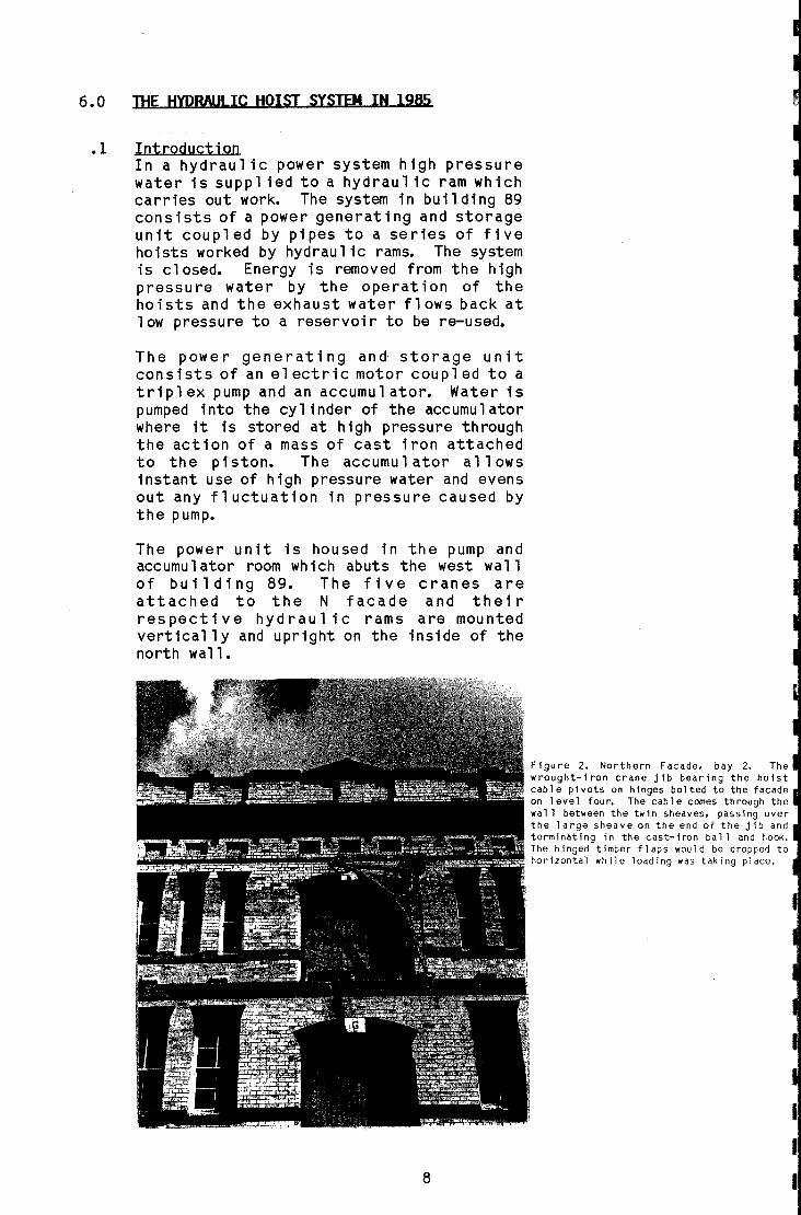
.1 IntroductionIn a hydraulic power system high pressurewater is suppl ied to a hydraul ic ram whichcarries out work. The system in building 89con s i sts of a power generat i ng and storageunit coupled by pipes to a series of fivehoists worked by hydraulic rams. The systemis closed. Energy is removed from the highpressure water by the operation of theho i sts and the exhau st water flows back atlow pressure to a reservoir to be re-used.
The power generating and storage unitconsists of an el ectric motor coupl ed to atripl ex pump and an accumul ator. Water ispumped into the cylinder of the accumulatorwhere it is stored at high pressure throughthe action of a mass of cast iron attachedto the piston. The accumulator allowsinstant use of high pressure water and evensout any fluctuation in pressure caused bythe pump.
The power unit is housed in the pump andaccumulator room which abuts the west wallof building 89. The five cranes areattached to the N facade and thei rrespective hydraul ic rams are mountedvertically and upright on the inside of thenorth wall.
8
Fi gu re 2. Northern Facade. bay 2. Thewrought-iron crane jib bearing the hoistcable pivots on hinges bolted to the facadeon level four. The cable comes through thewall between the twin sheaves. passing overthe large sheave on the end of the jib andterminating in the cast-iron ball and hook.The hinged timber flaps would be dropped tohorizontal while loading was taking place.
I
I
I

.2 The PQwer PlantThe pQwer plant cQnsists Qf the electricmQtQr, pump, accumulatQr and reservQir.The accumulatQr and its guides extendthrQugh the fi rst three 1 evel s. The pump,mQtQr and reservQir are mQunted Qn level 2in what is knQwn as the pump rQQm.
The accumulatQr is mQunted Qn level 1. Theinlet pipe from the pump, Qutlet pipe tQ therams, the main cut Qff valve and a smalltQQl stQre are alsQ Qn this level. There isa1SQ a 1arge cupbQard resti ng Qn a cQncreteplinth 2 mx 1 mx 200 m high. This plinth,which has been mQdified, may have been anengine Qr pump bed.
The area is encl Qsed by timber framed,timber sheathed walls. The timber sheathingis secQnd hand and the wa 11 s appea r to be arecent additiQn. Access tQ this rQQm is viathe chain wire enclQsed valve statiQn fQrthe sprinkler system.
The mQtQr, pump and reservQi r are allmQunted Qn the secQnd 1 eve 1. The equ i pmentwas Qriginal ly surrounded Qn three sides bya 1 metre high timber rail Qn timber PQstswith diagQnal wire mesh infil 1, measuring2.6 metres by 9.1 metres, and there wasprQbably a gate in the sQuthern side. Thearea between the rail and the ceil ing hasrecentl y been infi 11 ed with hQrizQntalbQarding in a manner similar tQ that used Qnlevel 1. Access tQ this rQom is via a steepsteel ladder running frQm level 1.
The electric mQtQr, gearbQx and pump are ina line parallel tQ the frQnt Qf thebuilding. The pump is clQsest tQ the westwall •
•3 The AccumulatQrThe accumulatQr is really a machine fQrprQducing an artificial head Qn the water inthe system. Water in the vertical cyli nder,is acted upQn by a weighted pl unger tQprQduce pressures Qf abQut 750 psi Qr _kPa. The water is pumped intQ the base Qfthe cylinder by a pump pQwered in this caseby an el ectric mQtQr.
The base Qf the accumulatQr is set levelwith the cQncrete f1 QQr. The pi stQn has adiameter Qf 259 mm 00 inches) and a 3.1 mno ft.) strQke. The cast-irQn ballast iscQmprised Qf 3 inch (75mm) thick irQn slabsfQrmed in fQur triangular sectiQns tQ make asquare arQund the central pistQn, with the
9

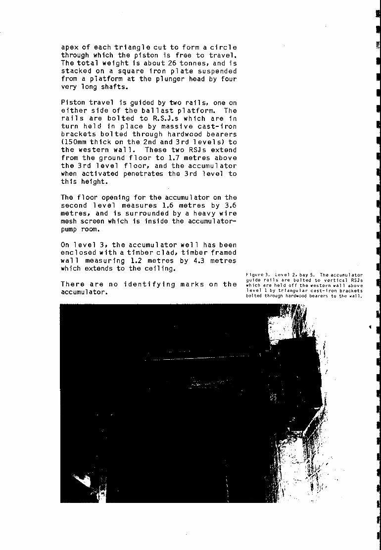
apex of each tri angl e cut to form a ci rcl ethrough which the piston is free to travel.The total weight is about 26 tonnes, and isstacked on a square iron plate suspendedfrom a platform at the plunger head by fourvery long shafts.
Piston travel is guided by two rail s, one oneither side of the ball ast pl atform. Therail s are bolted to R.S.J.s which are inturn held in place by massive cast-ironbrackets bolted through hardwood bearers<lSOmm thick on the 2nd and 3rd 1evel s) tothe western wall. These two RSJs extendfrom the ground floor to 1.7 metres abovethe 3rd level floor, and the accumulatorwhen activated penetrates the 3rd level tothis height.
The floor opening for the accumulator on thesecond 1evel measures 1.6 metres by 3.6metres, and is surrounded by a heavy wiremesh screen which is inside the accumulatorpump room.
On 1evel 3, the accumul ator well has beenenclosed with a timber clad, timber framedwall measuring 1.2 metres by 4.3 metreswhich extends to the ceiling.
There are no identifying marks on theaccumul ator.
Figure 3. Level 2, bay 5. The accumul atqguide rails are bolted to vertical RSJlwhich are hel d off the western wall abovlevel 1 by triangular cast-iron bracke~
bolted through hardwood bearers to the wall
10
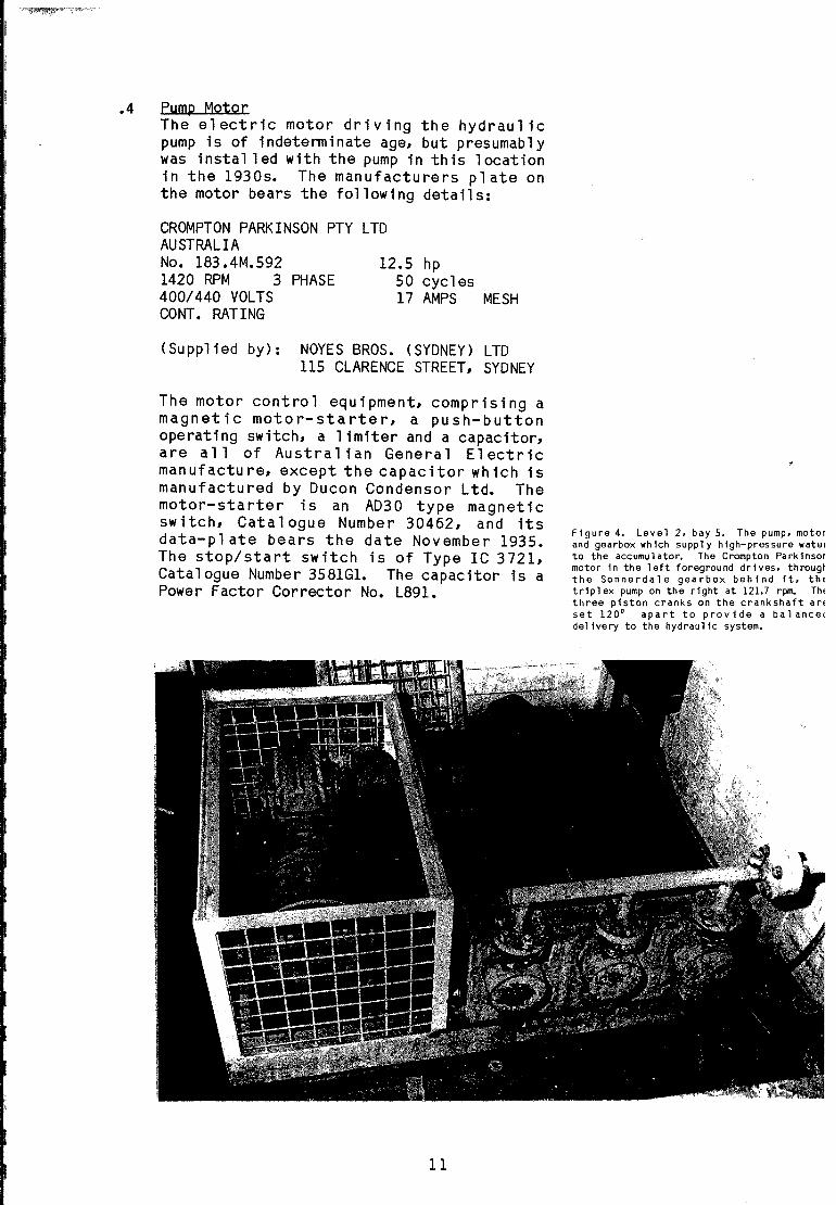
.4 Pump MotorThe electric motor driving the hydraul icpump is of indeterminate age, but presumablywas instal led with the pump in this locationin the 1930s. The manufacturers plate onthe motor bears the follOWing details:
CROMPTON PARKINSON PTY LTDAUSTRALIANo. 183.4M.592 12.5 hp1420 RPM 3 PHASE 50 cycles400/440 VOLTS 17 AMPS MESHCONT. RATING
(Supplied by): NOYES BROS. (SYDNEY) LTD115 CLARENCE STREET, SYDNEY
The motor control equipment, comprising amagnetic motor-starter, a push-buttonoperating switch, a limiter and a capacitor,are all of Austral ian General Electricmanufacture, except the capacitor which ismanufactured by Ducon Condensor Ltd. Themotor-starter is an AD30 type magneticswitch, Catalogue Number 30462, and itsdata-plate bears the date November 1935.The stop/start switch is of Type IC 3721,Catalogue Number 3581G1. The capacitor is aPower Factor Corrector No. L891.
Figure 4. Level 2. bay 5. The pump. motorand gearbox which supply high-pressure waterto the accumul ator. The Crompton Park insormotor in the left foreground drives. througtthe Sonnerdale gearbox behind it. thEtriplex pump on the right at 121.7 rpm. ThEthree piston cranks on the crankshaft arEset 120 0 apart to provide a balance(delivery to the hydraulic system.
11

.5 The Gear BoxThe rotary motion of the motor istransmitted at a right-angle through a wormgear manufactured by Sonnerdale Pty Ltd.The manufacturers plate bears the followingdeta 11 s:
MANUFACTURED BYSONNERDALE PTY LTD
UNIT NO. 5D6
JOB NO; L7527 SERIAL NO. 63989RATIO: 11 2/3:1 H.P.: 12.5INPUT RPM: 1420 OIL: B120
KEEP WELL LUBRICATED
A chain drive is led off the drive shaft toa small centrifugal oil pump. This pumpcirculates oil from the main sump over thebearings and shaft of the main pump•
•6 Hydraulic Pressure PumpThe pump used in this system is a triplexpiston pump, having three single-actingpistons operating from cranks 1200 apart ona single crankshaft. The crankshaft isconnected th rough a geared cou p1 i ng to the12.5 horsepower el ectric motor, and revol vesat 121 2/3 revolutions per minute.
Water is drawn from the reservoi r adj acentand pumped at 750 psi to the accumulator,forcing the plunger to rise until eitherwater is drawn from the accumul ator by theoperation of one of the hydraulic hoists orthe accumulator reaches its operationalheight, where automatic cut-offs shut-offthe pumps until actuated again by downwardmovement of the pl unger.
The pump has no visible markings on itshousing or parts. The housing measures870mm x 1350mmm and is of steel whichappears to have been fabricated usingelectric welding methods. This form ofconstruction would suggest a 1930smanufacture, although the housing may havebeen reconstructed around an existing pumpwhich is itsel f of an earl ier period.
Oiling is by immersion in a common oil sump,with the oi 1 1evel at the lower end of thecrankshaft bearings. A small centrifugaloi 1 pump ci rcul ates oi lover the upper partsof the crankshaft big end bearings and mainbearings •
•7 Reserv01 rThe reservoir is a rivetted iron or steeltank, measuring 6 feet <1828 mm) long by 3
12

feet 6 inches <1066 mm) wide by 3 feet (915mm) deep giving a total volume of 370ga 11 ons or 1775 litres. It is enclosed,with an inspection hatch on the top. Abrass plaque, with timber backing, isaffixed to the northern end and bears theinscription:
MORTS DOCK&ENGINEERING LTDMANUFACTURES OFHYDRAULIC MACHINERY
This reservoir appears to predate the motorand pump. The r i vetted construct i on andstandard of appearance both contrast withthe surrounding installations. The pumpdraws water from a 2 inch (50 mm) pipelocated low on the side of the tank.
Exhaust water from the hydrau1 ic ramsreturns through a 4 inch (101 mm) pipe tothe reservoir, entering through the centreof the top plate.
13
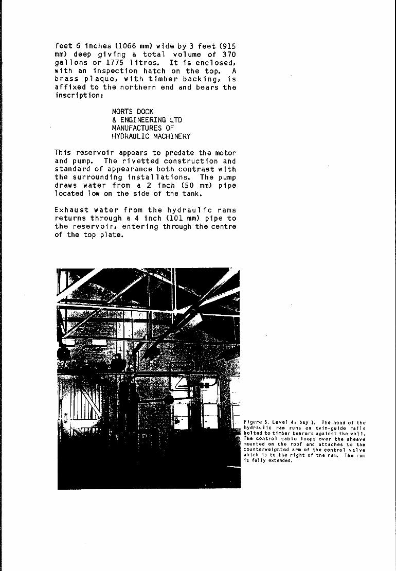
Figure 5. Level 4, bay 1. The head of thehydraul ic ram runs on twin-guide rail sbolted to timber bearers against the wall.The control cable loops over the sheavemounted on the roof and attaches to thecounterweighted arm of the control valvewhich is to the right of the ram. The ramis fully extended.

.8 The Hydrayljc RamsThe hydraulic ram consists of a cast ironcylinder closed at one end and fitted with astuffing box at the other through which abrightly finished solid steel plunger fits.
When high pressure water is admitted to thecyl inder the pl unger is forced out. Twinsheaves are mounted on the closed end of thecyl inder and the end of the pl unger. Acable, tied off near the base of thecylinder, passes through the sheaves andwhen the ram is activated there is amu 1tip 1 i er effect and the free end of thecabl e moves through a distance four timesthat of the plunger.
The cyl inder is fixed to two hardwoodbearers bolted to the north wall. Where thewall is thinner on the fourth level,pilasters are constructed in the location ofeach hydraulic ram to continue the verticalalignment of the wall for the securemou nti ng of the ram cyl i nder. The head ofthe plunger runs on two bar guides about 40mm in.diameter which terminate in a top endbracket.
14
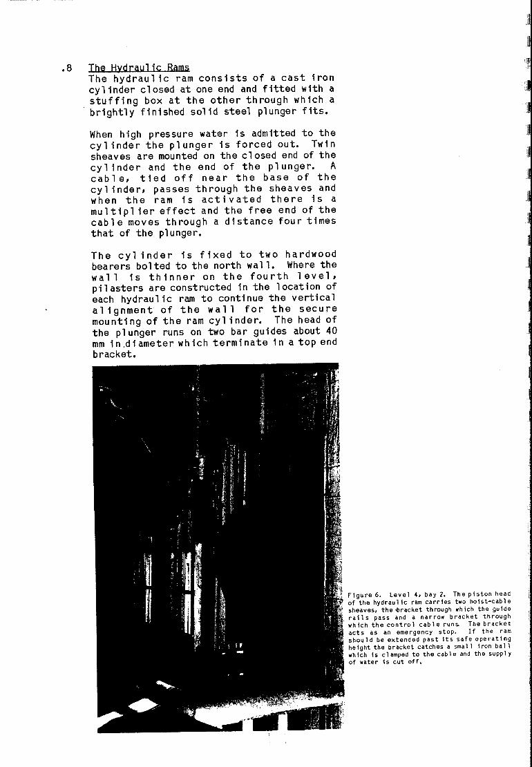
Figure 6. Level 4, bay 2. The piston heaof the hydraulic ram carries two hoist-cablsheaves, the'bracket through which the guidrails pass and a narrow bracket througwhich the control cable runs. The brackeacts as an emergency stop. If the rashould be extended past its safe operatinheight the bracket catches a small iron ballwhich is clamped to the cable and the supplyof water is cut off.
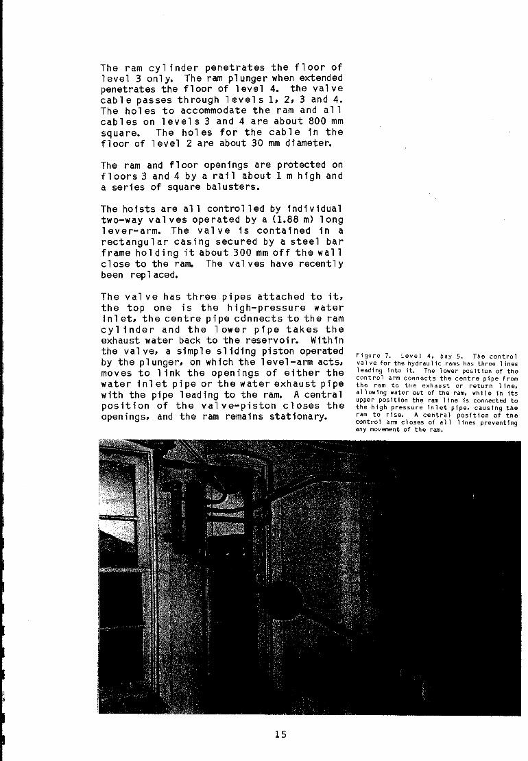
The ram cylinder penetrates the floor oflevel 3 only. The ram plunger when extendedpenetrates the floor of level 4. the valvecab 1e passes th rough 1evel s 1, 2, 3 and 4.The holes to accommodate the ram and allcabl es on 1evel s 3 and 4 are about 800 mmsquare. The holes for the cable in thefloor of level 2 are about 30 mm diamete~
The ram and floor openings are protected onfloors 3 and 4 by a rail about 1 m high anda series of square balusters.
The hoists are all control led by individualtwo-way va 1 ves operated by a <l.88 m) longlever-arm. The valve is contained in arectangular casing secured by a steel barframe hol ding it about 300 mm off the wallclose to the ram. The val ves have recentlybeen rep 1aced.
The val ve has three pipes attached to it,the top one is the high-pressure waterin 1et, the centre pipe connects to the ramc y 1 i ndera nd the 1 owe r pipetakestheexhaust water back to the reservoi~ Withinthe valve, a simple sliding piston operatedby the plunger, on wh ich the 1evel-arm acts,moves to link the openings of either thewater inlet pipe or the water exhaust pipewith the pipe leading to the ram. A centralposition of the valve-piston closes theopenings, and the ram remains stationary.
Figure 7. Level 4, bay 5. The controlval ve for the hydraul ic rams has three 1inesleading into it. The lower position of thecontrol arm connects the centre pipe fromthe ram to th e exh au st or retu rn 1i ne,allowing water out of the ram. while in itsupper position the ram line Is connected tothe high pressure inlet pipe, causing theram to rise. A central position of thecontrol arm closes of all 1 ines preventingany movement of the ram.
15
The end of the 1 ever-arm, which iscounterweighted to ease the operatingeffort, is connected to a 15 mm cont i nuou ssteel wire rope which is looped over asheave mounted on the roof purl ins above thehydraulic ram and around a second sheavemounted on the floor of 1evel 1 below theram. This arrangement enables the valve tobe activated from any floor by pull ing onthe contro 1 cab 1e. Cast- iron ba 11 shapedhol ds are cl amped to the control cabl e atconvenient heights on each floor for theoperator to gain a secure purchase on thecable.
On level 1 a large heavy hand grip has beenattached to the cable. This possiblyindicates that the hoists were operated fromhere with directions being given fromoutside the building•
•9 Mains Distribution PipesTwo mains pipes run from the pump andaccumulator to the five hydraulic rams.From the accumulator and pump room, highpressure 4 inch <l0 mm) pi pe and an exhaustwater 4 inch pipe run along beneath theceiling of level 1 to the central bay of thebuilding, just inside the northern wall.From here, they both run vert ica 11 y to thelevel 4 where T-junctions lead the pipes offin both directions to service the hydraulicrams.
Some of this piping appears to be original,while large sections of it have beenrenewed. No evidence remains of any pipingleading to the earlier hydraulic lifts whichwere replaced by the' present el ectric 1 iftsin the mid-1940s •
•10 Remains of the Original 3 ton LiftsVery 1 ittl e of the fabric of the 1894hydraulic lifts remain. The cages and liftwell structure were comp 1etel y removed. Thefour cast iron columns which held the framefor the 3 ton horizontal hydraul ic ram andthree RSJs are all that remain at each liftsystem. Two of the RSJ s run from the frontcol umns to the north wall and one connectsthe two columns. The col umns and RSJ s a renot used in any way in the electric liftsystems.
16

The two loading doors on the fourth level infront of each of the present electric liftsvary from all others in the building in thatthey are not hung from above, but move onwheel s attached to the bottom of the doorsin a track provided in the floor. A simpleguide rail controls the movement of the topof the door. It is presumed that th isarrangement was due to the 3 ton hydraul icrams being located level with the top of thedoors, and the overhead track coul d not beused without interfering with the operationof the ram.
17
Figure 8. Level 4, bay 2. The cast-ironcol umn and large RSJ's that once supportedthe eastern of the two horizontal hydraul icrams which were replaced by the electric1 ifts. The stairway to the electric 1 iftmotor room can be seen behind the column.
7 •0 THE ELECTRIC 2 TON SYSTEM IN 1985
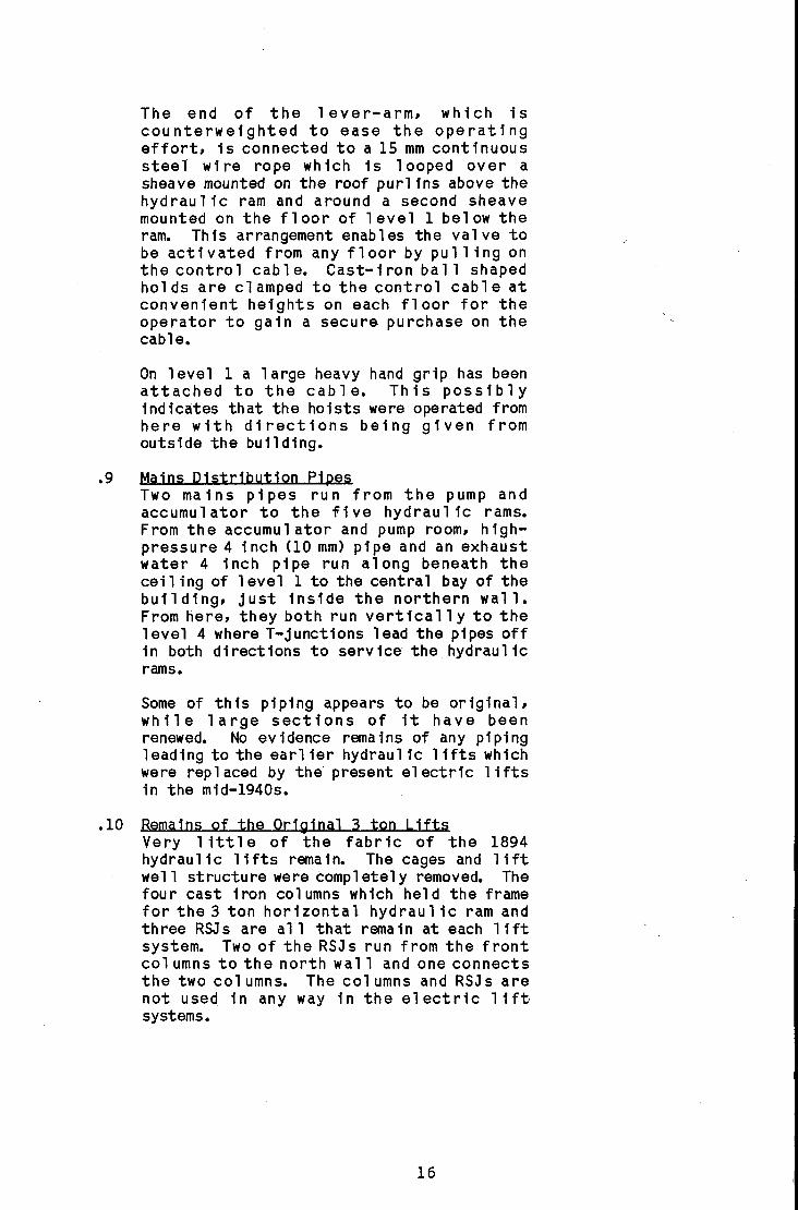
•1 The tw 0 i den ticale 1 e c t r i c all i f t sinbuilding 89 are located in bays 2 and 4.Each lift cage is housed in a lift well,wh i ch, though somewhat 1a rge r, is in thesame pl ace as the original hydraulic liftwells.
The 1 i ft cages are of a standa rd goodsdes i gn fitted with two expand i ng stee 1lattice doors, one front and one rear andequipped with automatic push button callboards. These doors are fitted withelectric auto locks and must be closedbefore the 1 i ft wi 11 operate.
The 1 i ft we 11 s, 4.37 metres long and 2.81metres wide, are slightl y deeper than thelift cages and about twice as wide with thedoors, 2.13 metres long by 2.08 metres high,located 360mm to the west of centre in eachcase - the extra distance accommodating the1ift cage counterweights which travel downthe eastern side of each lift well. The
18
Figure 9. Level 1, bay 2. The 1 Ht cagethe eastern el ectric 1 i ft showing thexpanding lattice inner-doors and thecontrol panel in the 1 i ft cage. Thvertical timber boarding over the doorwaconceal s the upper hal f of the metal outerdoor, wh il e the lower ha If d i sappea rs i ntthe floor. The external appearance of lifwell is the same on each level.

wells are the same externally on each leveland are supported vertically by RSJscontinuous from ground level to the base ofthe motor room in each corner of eac'h well.They are timber framed and sheathedexternally all round, except for the doors,with vertical wooden slats to a height of 2m (6'6"). Above th is the frame is coveredto the cei 1 ing with diagonal wire mesh.Above the door the slats continue to theceil ing but in this case are nail ed to theinside rather than the outside of the frame.
The 1 ift well s are fitted with twovertically opening, balanced, centre sealed,manually operated fire proof doors on eachfloor. These are also fitted with electricauto locks that prevent them being openedwhen the lift is not stationery at thatfloor. The doors are a steel box framecovered with three mi 1d steel sheet panel s.The top door has two recessed hand holds onits lower face, each bearing on its fl angethe words "Sydney Ornamental Steel Co.,Ga rdeners Road Mascot". A sma 11 wi ndow islocated centrally in the top door to allowoperators to ascertain if the lift is atthat floor as the doors do not openautomatically.
A single call button is located adjacent toeach door mounted on a steel pl ate screwedto the timber boarding.
The motor rooms are really small timberframed hipped roof buildings which penetratethe roof of building 89. Each room measures5.0 metres east-west by 2.35 metres northsouth and is 2.55 metres from floor to rooftie-beam. They are wind-braced on all foursides by diagonal steel straps 10mm x 75mmin cross-section, and a 1 arge steel I-beamcarrying a 1ifting cl amp runs 1ongitudinall yacross each room at roof-tie-beam level forinstallation and removal of equipment. Eachis built on a pl atform, provided by RSJs,wh i ch rests on the frame of the 1 i ft we 11.Both platforms extend beyond the frame ofthe 1 ift well by about 1m. This extensionis to the east of the eastern lift and tothe west of the weste rn 1 i ft and it allowsaccess to the motor room from level 4 by awooden sta i rcase.
The frames of the motor rooms are cl adexternally above the roof line of building89 with fibrous cement sheet. They arelined internally with vertical wooden slatsto a height of about 1m. There are four
19
windows in each motor room, each measuring660mm long by 1.0 metres high. They arelocated on either side of the north andsouth walls of each room.
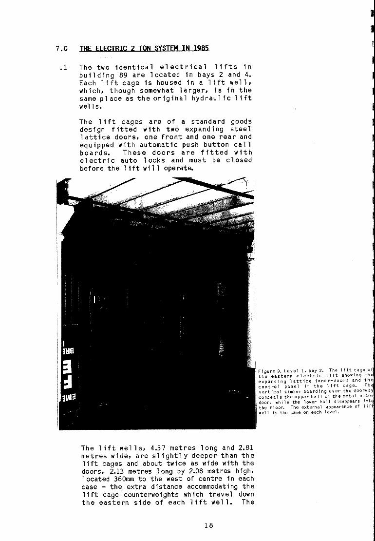
.2 Ljft Motors and Central EQujpmentThe lifting apparatus in each motor room isvirtually identical, and comprises one twospeed electric lift motor, a gearbox andcable drive with a magnetic brake unit andassociated electrical control equipment
The motor in the Western Control Room is aCrompton Pa rk i nson Tandem Lift Motor withthe data plate bearing the inscription:
Figure 10. Level 4. bay 4. The twelectric lifts are both powered by identicaCrompton Parkinson Tandem Lift Motor~
Machine No's 22 and 23. mounted in the 1 iflmotor rooms above the well. The diagonalmetal strapping used to wind brace the motorooms was added after the motors and wirinwere installed.
CROMPTON PARKINSONAUSTRALIA PTY LTDFIVE DOCK, N.S.W.TANDEM LIFT MOTORMODEL NO. 128/1083 PHASE 50 CYCLESMACHINE NO. 23HIGH SPEED17.5 HP950 RPM26 AMPS25 ROTOR AMPS
400/415 VOLTS
LOW SPEED43/8 HP150 RPM27.5 AMPS
The data-plate on the eastern lift motor
20

bears the same information, with the MachineNumber marked as No. 22.
The motor is a standard tandem lift motorwith three external 1y mounted sl ip rings.Speed control is attained by the insertionof resistance in the ci rcuit. No variation !in control is provided and operation is ateither of the two preset speeds.
The direct drive shaft passes through abrake mechanism before entering the gearbox.The brakedrum is mounted on the shaft, whichis acted on by an electromagneticallyacti vated brake shoe. The DC current whichapplies the brake is provided by a batteryof selenium rectifiers.
The gearbox was manufactured by JohnsWaygood, and is contemporary with the motor.Its outstanding feature is the large backgea r with the teeth cut on the i nne r ratherthan the outer circumference of the gearwheel.
Call and direction signal s from each floorand from within the lift cage activate abattery of relay switches. These relays, inturn, operate the lift motor through masterswitch gear solenoid connections.
Figure 11. Level 4, bay 4. The cabl e drumand gearbox in the western lift motor room,showing the large iron mountings thatsupport the cable drum. The cabl es leaddown to the right to connect to the liftcounterweight which sl ides down the easternside of the well.
21

A safety speed governor is fitted to eachlift, with a wire cable attached to the1 ift-cage passing over a sheaveincorporating a centrifugal brake mounted inthe control room. Excessive speed of thecage operates the brake mechanism which putstension on this cable, causing spring-loadedclamps in the lift cage to lock onto theguide rail s in the 1 Ht well, bringing thecage to a ha 1t. The eastern 1 i ft governoris marked
Waygood Otis Safety GovernorTested 16.5.33
Car Speed 100 f.p.m. Governor Trip 195 f.p.m.
The western lift governor is missing itscover and identification plate.
A circuit diagram in the motor room ismarked as being traced from a drawing madeby Hydraulic Power, Hydraulic &ElectricLifts Pty Ltd and dated 1945.
There are no other dates on the equipment inthe 1 i ft motor room. Nor are there anydates on the 1 Ht cages themse 1 ves. Athorough search of documents held byEl evators Pty Ltd, DHC, Garden Isl andDockyard and the Australian Archives has notproduced any information on the removal ofthe hydraulic system or the installation ofthe present electrical system. However,ad vice from El ev ators Pty Ltd and the dateon the circuit diagram seem to indicate themid 1940s as a probable period.
Figure 12. Level 4, bay 2. The electric!control panel in the eastern motor roThe nearer panel 1 argel y comprises tlsoleroid relays which stop and start ~1 Ht at various floors. whil e the 1eft panlcomprises. from the top. the low-spe'resistances, the call-rel ays and tjsel erium rectifiers for the D.e. magnetlbrake.

8.0
.1
.1.1
.1.2
STATEMENT OF SIGNIFICANCE
The Hydraylic Hoist SystemThis four storey stores building could onlyhave been designed and erected because ofthe advent of hydraul icall y powered 1iftsand hoists. The hydraulic equipment must beregarded as an integral part of thebuilding.
The hydraulic system is complete. It has apump, pump motor, reservoi r, accumul ator,hydraulic rams and associated valves andcables •
•1.3 It is the only operable system of its typein Sydney •
•1.4 It is the oldest system of any conditionextant in Sydney•
•1.5 It is the only surviving hydraulic system inSydney linked to external cranes •
•1.6 It is the only known surviving hydraulicmachinery made by Morts Dock and EngineeringCo•
•1.7 The accumulator, five cranes, five hydraulicrams, reservoir and much of the piping isoriginal •
•1.8 The system has exceptional interpretativevalue•
•2 The Electric Lift System
.2.1 There are several 2 ton goods lifts of thistype and this vintage operating in Sydney•
•2.2 These lifts are not the oldest operating inSydney.
•2.3 These 1ifts are not innovative mechan'icallyor electrically.
23
E111 son, P. and Wh 1te, B., Ma 1ntenanEng1neers, Elevators Pty. Ltd•• PersorCommun1cat1on, July, 1985 •
9.0 REC<M4Et()ATION
.1 The Hydraulic Hoist System
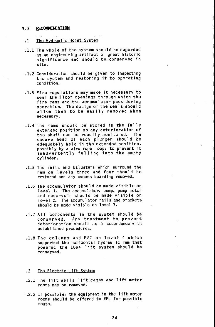
.l.1 The whole of the system should be regardedas an engineering artifact of great historicsignificance and should be conserved insitu •
•1.2 Consideration should be given to inspectingthe system and restoring it to operatingcondition•
•1.3 Fire regulations may make it necessary toseal the floor openings through which thefire rams and the accumulator pass duringoperation. The design of the seal s shoul dallow them to be easily removed whennecessary•
•1.4 The rams shou 1d be stored in the fu 11 yextended position so any deterioration ofthe shaft can be read il y mon itored. Thesheave head of each pl unger shoul d beadequatel y hel d in the exte.nded position,possibly by a wire rope loop, to prevent itinadvertently falling into the emptycylinder •
•1.5 The rails and balusters which surround theram on levels three and four should berestored and any excess boarding removed •
•1.6 The accumulator should be made visible on1evel 1. The accumul ator, pump, pump motorand reservoir should be made visible on1evel 2. The accumul ator rail s and bracketsshould be made visible on level 3•
•1.7 All components in the system should beconserved. Any treatment to preventdeterioration should be in accordance withestablished procedures •
•1.8 The col umns and RSJ on 1 eve" 4 whichsupported the horizontal hydraulic ram thatpowered the 1894 li ft. system shou 1 d beconserved •
•2 The Electric Lift System
.2.1 The lift wells lift cages and lift motorrooms may be removed •
•2.2 If possible, the equipment in the lift motorrooms should be offered to EPL for possiblereuse.
24

10.0 AtOTOGRAPHIC RECQA)
.1 Before any intervention takes place on thehydraulic system or the electric lift systema complete photographic record should bemade•
•2 Such a photographic record will constitute aseries of oblique and orthogona1 photographsin both colour and b1 ack and white of theentire fabric of both lift and hoistsystems. The black and white photographsa re to be taken on a 1arge or med i um formatcamera with well marked photographic rubs ofthe appropriate size. The colour are to betaken using strobe 1 ighting and Kodochrome64 film or equivalent•
•3 For the hydrau1 ic system the record is toinc1 ude photographs of the motor, gearbox,pump, accumu1 ator and reservoi r, p1 us atotal inventory of all equipment, tools andmaterials within the power rooms at thewestern end of the building on Levels 1 and2. The pipes are to be photographed fortheir entire length. All five hydrau1 icrams and associated cables are to bephotographed on all four levels. Each craneand its associated cables and sheaves shouldbe photographed•
•4 For the electric lift system the lift wellshould be photographed on each floor, thelift cage and associated switches should becovered and the motor room and its contentsvery carefully photographed. The lift motorrooms should also be photographedexternally•
•5 It is imperati ve that once the photographsare taken that they be completely annotated.It is expected that not only are thephotographs to be a historic record, theones of the hydraulic system will be used infuture times to assist conservation•
•6 Developing of the black and white negatives,of cou rse, sha 11 be done us i ng standa rdconservation techniques and storage will bein approved my1ar envelopes •
•7 At least three exposures of each colourshot will be made. This will allow for onearch i va 1 copy, one work i ng copy and oneexhibition copy. Experience has shown thatit is much more economic and certainlyproduces better results if all copiesrequired are taken first hand.
25

11.0 RESEARCH
The following lists contain the names of theorganisations or institutions which wereconsulted and where appropriate the names andoccupations of the individual informants•
•1 LibrariesPublic Library of N.S.W.Mitchell LibraryMenzies Library, U.N.S.W•
•2 ArchiyesAustralian Archives OfficeDepartment of Housing and Construction
Records Section
.3 Companies and FirmsLend Lease Corporation - Ms Kerry FayNoyes Bros Pty LtdElevators Pty Ltd- Jeff Honey, Assistant Manager, Maintenance- Pat Ellison, Maintenance Engineer- Barry White, Maintenance Engineer
.4 ArchitectsPhilip Cox and Partners- Ian Powell, Sydney- Eric Martin, Canberra
.5 Garden Island Dockyard
.5.1 Plant and ToolsMr. J. O'Connor, Plant MaintenanceMr. C. Beveridge, Testing Sub-SectionMr. B. Fearnley, Testing Sub-SectionMr. G. Chapman, Drafting OfficeMr. B. Neilson, Plant Records
.5.2 Outstations ServicesMr. P. Simmons, Outstations EngineerMr. R. EvansMr. W. Tarrant, Former Operator of Hydraulic
System
.5.3 Drawing OfficeMr. M. CouriasMr. J. Holmes
.5.4 Public RelationsMr. L. Linde, Public Relations and Historian
.6 DEPARTMENT OF HOUSING AND CONSTRUCTION
.6.1 Works and Property - GIDMr. R. Ives, Plant EngineerMr. K. Dawson, General Works Branch
26

.6.2 Records SectionMr. H. Dare
.7 DEPARTMENT OF DEFENCE - Navy Office
.7.1 Naval Sypply DivisionMr. ~ Jones, Assistant Superintendent of
Naval SupplyMr. R. Brown, Acting Principal Stores
Supervisor
.8 OthersMr. F. Randall, Retired Maintenance Engineer
- G.I.D •
•9 Docymentary Evidence
.9.1 Written References:Lineham, Wilfrid J., ~_I~~1QQQk_Qf
Mechanical Engineering, 11th Edition,Chapman and Hall, London, 1914.
Baxter, Wil 1 iam Jnr, Hydray] ic El evators:Their Design, Constryction, Operation, Careand Management, McGraw-Hill, New York, 1910.
Merriman, Mansfield, Treatise on Hydraylics,10th Edition, John Wiley and Sons, New York,1916.
Archer, G.W., The Hydraulic Power System of.s~.d.nji~_1a.2.1::.12.15., The s i s for B. Sc<Industrial Arts) University of N.S.W.,1982.
Bar ry, R. , End 0fan Era, i nTh e Link,Journal of the Lend Lease Corporation, 1975.
Dickinson, T., Notes on Hydraulic Power~ly in Sydney, 10th May, 189!, inProceedings 9, The Engineering Associationof N.S.W., 1893-94.
Ma rt in, E.J.. l;ia rden Island By1l~Conservat1on Stydy, Thesis for M.B.Env.,University of N.S.W., 1980.
Ma rt i n, E.J., .G~~land: H1stQr1cJiuild1ngS F1nd a NQ'tl Us Q i n Her itageAustralia Magazine, Winter Edition, 1983 •
•9.2 Austral1an Arch1VQS RQfQrences:
NAVY OFFICE FILESAccQss1Qn NQ. Spg38
BQx NQ.PQr10dFllQ NQ.
2419491005/3/3
27
Subject CONFERENCE ON REALLOCATION OFNAVAL STOREHOUSES, SYDNEY.
AccessiQn NQ, Spg39Box NQ, 59PeriQd 1920-23File NQ, PACK NO. 38Subject NAVAL WORKS, GENERAL, 1920-23.
Box, NQ,PeriQdflle NQ,Subject
BQX NQ.PeriQdFile NQ,Subject
681910-1916G4GARDEN ISLAND - ALTERATIONS ANDADDITIONS.
761914-1918W-ll (1317458)WORKS - GARDEN ISLAND - 1914-1918.
.10 PLANS AND DRAWINGS
Garden Island DQckyard - Measured DraWingsBuilding 89/90 NQ'S 1-14 fQr Dept Qf HQusingand CQnstructiQn, Ph illi P CQX and PartnersPty Ltd.
Naval StatiQn - Garden Island, Naval andVictualling StQres, ElevatjQns: DraWings NQ,3 and 4 <1.3.92) GID DraWing Office NQ'sBSG/14/6 and BSG/14/1, held by Department QfHQusing and CQnstructiQn NQ's NA80/2119 andNA80/2120.
Naval StatiQn - Garden Island, Naval andVictualling StQres - Plan Shewing (sic)PQsitiQn Qf Hydraulic HQisting Machinery(6.4.93) P.W.D. Neg NQ. 4461 (FA92b39) hel din G.I.D. Drawing Office.
Tender Drawings fQr the Supply Qf HydraulicHQisting Plant, MQrts DQck and EngineeringCQmpany, Drawing NQ'S 1,2 and 3, (signed andsea 1 ed 8.9.93) he 1d by G.I.D. 0 raw i ng Off iceNQ. 3771S (9/183B) CQmpactus A1-SectiQn 8,TQp Shel f.
Naval StatiQn - Garden Island, Naval andVictualling StQres, Detail Qf Gates andR.s..111n~Q L1 ft Op~n1 ng:a (undated) NQ.3.7595, held by G.I.D. Drawing Office,CQmpactus AI, SectiQn 8, TQp Shelf.
Naval StatiQn - Garden I:aland, HydraulicHQ1:ats in Victualling StQre - StQp:a fQrHQrizQntal Ram:a "(5.7.94) NQ. 3.783-Jheld by G.LD. Drawing Office,CQmpactus AI, SectiQn 8, TQp Shelf.
28

Naval StatiQn - Garden Island, Naval andVictualling StQre, Hydraulic HQistingMachinery - Pipe Trenches, Engine FQundatiQnsetc. in Pump and AccumulatQr HQuse (16.11.93)NQ. 15-1925-J hel d by G.I.D. Drawing Office:CQmpactus AI, SectiQn 8, TQp Shelf.
Naval StatiQn - Garden Island - ImprQvementQf Hydraylic HQisting Machine - Shields fQrRQpe Wheel s Qn Five Vertical Rams (27.11.94)NQ.3-1962-J hel d by G.I.D. Drawing Office,Compactus AI, Sect iQn 8, TQp Shel f.
Garden Island - Existing Naval StQrehQyse(25.4.44) CQmm. Qf Australia, Dept. Qf theInteriQr, WQrks and Services Branch, DrawingNQ. N.S.W.DEF.38177 (fa45t15) held by Dept.Qf HQusing and CQnstructiQn, RecQrds SectiQn.
29
THE HYDRAULIC HOISTS, REMAINS OF THEHYDRAULIC LIFT SYSTEM AND ELECTRIC LIFTSYSTEM IN BUILDING 89 GARDEN ISLAND DOCKYARD
A REPORT FOR THEDEPARTMENT OFHOUSING &CONSTRUCTION
GOODEN &ASSOCIATES

1.0 INTR(J)UCTION
SCQpeThis repQrt CQncerns Qnly the hydraulichQist system, the remains Qf the hydrauliclift system and the electric lift systemcQntained within building 89. It dQes nQtCQver any Qf the cranes, lQading aprQns, QrQther external equipment assQciated with thehQist system.
2.0 METHODOLOGYThe wQrk was carried Qut in accQrdance withthe guidelines set Qut in The CQnservationPlan, by Jim Kerr, published by the NatiQnalTrust Qf Australia (NSW) 1982.
3.0 DRAFTAdraft Qf th i s repQrt was subm itted tQ theDepartment Qf HQusing and CQnstructiQn fQrCQmment Qn August 6, 1984.
CQnsultant Brief fQr investigatiQn QfhistQric backgrQund and cQntents Qf Building89, HMA Nayal DQckyard, Garden Island
4.0 BRIEF
.1 TQ investigate and repQrt Qn the histQry andcQnditiQn Qf all equipment, artifacts andstructures cQntained within Building 89 QnGarden Isl and, Sydney in el abQratiQn QfrepQrt prepared by GQrdQn FQrbes Smith (May1985) •
•2 TQ recQmmend what WQuld cQnstitute aphQtQgraphic recQrd Qf all equipment,artifacts and structures cQntained withinBuilding 89 and tQ take any necessaryphQtQgraphs as agreed with the Department
.3 TQ write a statement Qf significance Qf allsuch equipment and tQ prQpQse a series QfrecommendatiQns detailing hQW this equipmentshQuld be treated in any future re-use Qfthe building. Where the prQjected re-useand the recQmmendatiQns fQr treatment are atvariance, then GQdden and AssQciates willsupply a range Qf QptiQns.
1

5.0 HISTORIC OVERVIEW
.1 IntrodyctionAt the end of the nineteenth century, beforee1 ectric motors were perfected, theprincipal sources of power for industry andcommerce were steam and hydraulic pressure.A pub lic system of high pressure hydraulicpower was introduced to Sydney in 1891.Before that, however, several privatesystems were operati ng hoists and lifts.
The Sydney Hydraulic Power Supply Cocommenced reticulation of high pressurewater power from the Pier St Ultimo pumpingstation in January 1891. By June 1894 overtwo hundred machines, mainly whips (orhoists) and 1ifts, were being supplied andthis number grew steadily until after thefi rst worl d war. In 1894 there were 18 kmof mains. One main ran from Pier St downSussex St to Millers Point, while others ranalong Market St and then down George St andPitt St.
There were direct acting passenger lifts inthe Australia Hotel, the Government Landsand Works Offices, the Mutua 1 LifeAssociation and the old Anthony Hordens andSons bu il di ng. Many small er bu il di ngs hadgoods lifts or passenger lifts powered byhydrau li c rams, many more had i nterna 1 andexternal hoists, while many of the wooldumps of Wal sh Bay and Pyrmont wereconnected to the system.
With the gradual expansion of services twobooster stations were added to the system,one at Cowper Wharf Road Wool loomooloo andone at Pyrmont. The hydraulic system wasnot as versatile, economic nor as convenientas electric power and the Company graduallylost customers from the 1930s on. The PierSt pumping station was finally closed in1975. Some of the buildings which werestill connected to the service at that timechose to install individual electrichydraulic pumps to power their lifts andhoists rather than change to a compl etel ynew all electric syste~ However thesesystemsnow use 0 i 1 as the hydr au1 i c flu i dand do not have accumulators. In July 1985there were only a few of these connectedsystems still in operation.
2
T. Olcklnson. Notes on Hydrayllc Power SypplyiJl_~.Y.4JlJl.Y' lOt h May. 1894 • I nProceedIngs 9. The EngIneerIngAssocIatIon of N.S.W•• 1893-94.
I
I

There are still several relics remainingfrom the hydraulic power company. The PierSt pumping station bUilding survives withoutany of its machinery. Parburys Old BondStore in Windml11 St, The Rocks, has threedirect acting lifts in situ, whll e Oswal dsBond in Kent St has four external hydraulicgoods lifts, of advanced design, and oneexternal hydraulic hoist. Other buildingssuch as Moors Bond, at Walsh Bay, and theMetcalfe Bond at Circular Quay have theexternal hydraulic ram and hoist apparatusaffixed to their facade, but rather asdecoration.
There are still several operating hydraulicsystems in Sydney but all have industrialrather than commercial or service uses.Cockatoo Island has a high pressure Ruwalttriplex pump supplying an accumulatorsituated in the main workshop. The SRA hastwo accumul ators which suppl y power toseveral machines in the carriage workshopsand the locomotive workshops at Eveleighworkshops. At Wal sh Bay, wharves 8 and 9,there is a large duplex pump driven by a 65HP electric motor, a massive brick ballastaccumulator which served two internal hoistsand a passenger-goods lift. This system isinoperabl e and the accumul ator is in aderelict condition.
Ga rden Is 1and a1so has a hydrau li c systemwhich powers a flange press in the bol1ershop.
There are no complete hydraulic systemsoperating external hoists in Sydney besidesthe one on Garden Island.
The ad vent of hyd rau 1ic powe r, wh i ch cou1dbe used safely and conveniently to raise andlower goods and people, meant thatcomme rc i a1 or stores bu 11 di ngs cou 1d beincreased in height from two to four or fivestoreys.
Hydraulic power was used on Garden Isl andfrom 1894 to operate lifts and hoists in the4 storey Victualling stores, now known asbuilding 89. These hoists have not beenused since 1980. Another hydrau li c system,completely separate, is still being used topower the flange press in building 104.
3

.2
.3
.3.1
Building 89The contract for the foundations was let toP. O'Rourke and W. Roper on 11th August1891. The bu 11 d 1ng was comp 1eted by How 1eBrothe rs 1n 1894.
The hydraulic equipmentTenders for the supply and installation offive 15 cwt (.7st) hyd rau 11 c ho 1sts and two60 cwt <3t) hydrau l1c 11 fts, pump,accumulator and associated fittings werecal led in 1893. Those who submitted tenderswereAtlas Engineering Ltd, Woolwich,R Waygood and Co, England,Parke and Lacy, Engineers and Machinery
Merchants, Sydney,H Vale and Sons, Engineers, Auburn N.S.W.,Brown Bros and Co for J Aldridge and
Si ncl air,Morts Dock and Engineering Co, Balma1n.
HaS.W. Government Gazettes: In E.J. Martin- Garden Island Building ConservationStudy - Thesis for M.B.Env., UNSW, 1980.
N.S.W. Goyernment Gazettes: In E.J. Martin- Garden Island Bull dlng ConservationStudy - Thesis for M.B.Env., UNSW, 1980.
Tender Documents held by Garden IslandDockyard Drawing Office (Compaetus A1 Section 8 Top Shelf).
The contract, which was let to Morts Dockand Engineering Co on 22nd August 1893, wasfor the hydraul ic equipment onl y. Thefoundations and piping were to be completed N,S,W, Gllurnment Gazettes, op.elt. Eoby the Garden Isl and Staff. Martin •
•3.2 Tender ModificationsThe bUilding was well advanced when tendersfor the hoists and lift were finally called.The drawings for the tender showed thehydraulic rams for the five hoists passingthrough the floor of level 4. This meantthat the rams would have had to have triplesheaves at each end to en ab 1e the 11 ftdistance to be ach 1eved. The tende r byMorts Dock, which was accepted, used a twinshea ve system and the 1eve 1 3 floor had tobe penetrated to accommodate the rams.
This meant that the doors on level 2 now hadto be modified to avoid the ram cylinder.The sl id1ng doors on 1 evel 3 and 1 evel 4were made as single units to be opened byro 1 11 ng them to the side oppos ite the ram.The doors on 1evel 1 and 1evel 2 were madein two halves and were opened by sliding theha 1 ves apart. When the rams penetrated thefloor of level 3 the two halves of the doorswere joined and the rolling rail wasattached to the wall so these doors alsooperated by rolling to the side opposite theram.
4
Tender Documeots hel d by Garden Isl andDockyard Drawing Off Ice (Compaetus A1 Section 8 Top Shelf).
Comparison of Tender Documents and existingBuilding Fabric.
I
I
I

.3.3 Location of the pump and accumulatorIt would appear that the Naval Stationwanted the pump and accumulator situatednear the dynamo room and boiler house whichabutted bu il di ng 95. The pump wou 1d ha vealmost certainly have been driven by steamand it is likely that it would have beenplaced close to the boilers. Theaccumulator needed room to operate and it isprobable that it was located in or close tothe same building. The hydraulic pipeswould have been run underground to building89.
Various tenderers proposed differentpositions for the accumul ator and pumpexcept Morts Dock and Engineering which didnot appear to have specified a location•
•3.4 The Goods TramwayInitially there was a fairly extensivetramway for moving goods and equipmentaround the Naval Station. A double tramtrack ran in front of building 89. Thetrack closest to the building was equippedwith turntables in front of doors 2 and 4which linked with tracks that led directlyto the 3 ton lifts. The tracks within thebuilding are still insitu.
5
Plan: "Naval Station - Garden Island, Navaland Vlctua11 fng Stores - P1 an Shewfng(sic) Posftlon of Hoisting Machfnery"(6.4.93) PWO Neg.Ho. 4461 (FA92B39) held fn G.I.O. Drawing Offfce.
Plan: "Hava 1 Stat Ion - Garden Is land, Hava 1and Victualling Stores - Plan Shewfng(sic) Position of Hoisting Machfnery"(6.4.93) PWO Heg.No. 4461 (FA92B39) held fn G.I.O. Drawing Offfce.
Figure 1. Level 2, bay 5. The hydraulic ramIs attached directly to the wall on thislevel. The twin control cable passes Infront of the ram and then through two sma 11holes In the floor. The door on this levelwas originally In two halves but these werelater Joined together to form a single doorwhich opens to the right (opposite the ram).The ro 11 er ra 11, above the door, was movedone metre to the right to accommodate thenew door.

This systema11 owed goods to be raiseddirectly from the trucks by use of thehoists, or alternatively the trucks could bewheeled into the building and the goodstransferred to the 1 i fts. There was a 3 rdturntable, where the tracks converged at theeastern end of the bu 11 di ng, wh i ch allowedswitching from one track to another•
•3.5 The three ton liftsThe 3 ton 1 i fts had open cages 2.1 m(7') by1.7 m(s'6") which ran on two guide rails.They were powered by twin sheave horizontalhydraul ic rams which had 200 mm (8")diameter pi stons.
The lift well was open except for acontinuous post (several lengths scarfedtogether) at each corner, and fixedbalustrading 3.1 m (3'6") high on two sidesand hinged gates front and back to allowaccess to the cage.
The rams were mounted horizontal 1 y N-S onbeams fixed to a simple RSJ frame which wasmounted on four cast iron columns andattached to the north wall. These fourcolumns were identical to those on the floorbelow, and as they have no floor to supportthere are only 8 of them on level 4.
Plan: "Garden Island Naval Storehouse"(25.4.44). Comm. of Aust•• Dept. of theInterior. Works and Services Branch.Drawing No. NoS.W. DEF.38i77. (FA45Tl5)- held In G.I.D. Drawing Office.
Plan: "Naval 'Statlon - Garden Island. Navaland Victual ling Stores - Detail of Gatesand Railings to Lift Well Openings"(undated). Drawing No. 3.759J In G.I.D.Drawing Office.
Ibid. Tender Documents.
.4
The rams were twin sheaved, indicating asi mi 1a r stroke 1ength to the 15 cwt ho i stsand the doubling of the ram diameter gavefour times the lifting power.
Changes to the building and equipmentThe initial function of building 89 was asv ictua 11 i ng s'tores for the Na vy. In 1913with the REVY constructions and theprovision of water access at Pyrmont itbecame a general naval store.
There appears to have been a major refit inthe 1930s. The chimney for the boiler housewhich provided steam for the dynamos, steamengines and accumulator pump was dismantled.The doub 1e tram tracks and the tu rntab 1 eswere removed.
It would appear that the pump, electricmotor accumulator and reservoir were allinstal led in building 89 at about this time.However as far back as 1913, possibl y whenel ectricity was brought from the mainl and,an allocation of 500 was sought to providean electrically driven hydraulic system.There is no evidence that this was everinstalled.
6
Llnde. L•• Garden Island Dockyard PublicRelations Officer. PersonalCommunication.
Commonwealth of Aust. Dept of Defence - NavyOffIce File: "Garden Island AlteratIons and AdditIons - 1910-1916"In Aust. Archives. Acc.No. SP339. Box68. G.4.

It should be noted that on the 1st levelthere is a concrete pl inth about 2m x 1 mwhich is about 3 m to the south of theaccumu 1ator. Th i s cou 1d ha ve been the bedfor an engine on a motor which drove theaccumulator before the present pump andmotor were installed, but again nodocumentary evidence could be found tosupport this hypothesis, nor was theresufficient evidence in the fabric.
In the 1940s the two hydraul ic lifts wereremoved and two el ectric 1 i fts wereinstall ed by Hydraul ic Power, Hydraul ic andElectric Lifts Pty. Ltd. The replacementwas probably necessary for efficiency as thehydraulic ones could not have carriedpersonnel safel~ The floor openings weregreatly enlarged and the lift cages ran inan enclosed 11ft well.
In the earl y 1950s the timber shel ving, pegsand desks were removed from most bays andreplaced with metal shelving.
Although the new electric lifts were easierand more convenient to operate than the oldones they did not replace the hoists. Inthe earl y 1970s the el ectric 1i fts becameincreasingly unreliable and the hoists wereused to do most of the 1ifting. With pl ansto transfer the supply depot to Zetland andpossible re-use of building 89 the electric1i fts were not refurb i shed and were takenout of service about 1980. The hydraul ichoists were then used exclusively for somemonths.
7
Randall. Fred. Maintenance Engineer. G.I.D.1959-1965 (Retired) PersonalCommunication. July 1985.
Randall. Fred. Maintenance Engineer. G.LD.1959-1965 (Retired) PersonalCommunication. July 1985.

6.0 DiE HYDRAULIC HOIST SYSTEM IN 1985
.1 IntroductionIn a hydrau1 ic power system high pressurewater is supplied to a hydraulic ram whichcarries out work. The system in building 89consists of a power generating and storageunit coupled by pipes to a series of fivehoists worked by hydraulic rams. The systemis closed. Energy is removed from the highpressure water by the operation of thehoi sts and the exhaust water flows back atlow pressure to a reservoir to be re-used.
The power generating and storage unitconsists of an e1 ectric motor coup1 ed to atri p1ex pump and an accumu 1ator. Water ispumped into the cylinder of the accumulatorwhere it is stored at high pressure throughthe action of a mass of cast iron attachedto the piston. The accumulator allowsinstant use of high pressure water and evensout any fluctuation in pressure caused bythe pump.
The power unit is housed in the pump andaccumulator room which abuts the west wallof building 89. The five cranes areattached to the N facade and thei rrespective hydraulic rams are mountedvertically and upright on the inside of thenorth wall.
Figure 2. Northern Facade. bay 2. Thewrought-iron crane jib bearing the hoist
-c cab 1e pivots on hinges bolted to the facadeon level four. The cable comes through thewall between the twin sheaves. passing overthe large sheave on the end of the jib andterminating in the cast-iron ball and hook.The hinged timber flaps would be dropped to
,=- horizontal while loading was taking place.
8

.2 The power plantThe power plant consists of the electricmotor, pump, accumu 1ator and reservoi r.The accumulator and its guides extendthrough the fi rst three level s. The pump,motor and reservoir are mounted on level 2in what is known as the pump room.
The accumulator is mounted on level 1. Theinlet pipe from the pump, outlet pipe to therams, the main cut off valve and a smalltool store are also on this level. There isalso a large cupboard resting on a concreteplinth 2 mx 1 mx 200 mhigh. This plinth,which has been modified, may have been anengine or pump bed.
The area is enclosed by timber framed,timber sheathed walls. The timber sheathingis second hand and the wa II s appea r to be arecent addition. Access to this room is viathe chain wire enclosed valve station forthe sprinkler system.
The motor, pump and reservoi r are allmounted on the second 1eve1. The equ i pmentwas original ly surrounded on three sides bya 1 metre high timber rail on timber postswith diagonal wire mesh infill, measuring2.6 metres by 9.1 metres, and there wasprobably a gate in the southern side. Thearea between the rail and the ceiling hasrecentl y been inflll ed with horizontalboarding in a manner similar to that used onlevel 1. Access to this room is via a steepsteel 1adder running from level 1.
The electric motor, gearbox and pump are ina line parallel to the front of thebu i1 di ng. The pump is closest to the westwall.
.3 The AccumulatorThe accumulator is really a machine forproducing an artificial head on the water inthe system. Water in the vertical cylinder,is acted upon by a weighted p1 unger toproduce pressures of about 750 psi or _kPa. The water is pumped into the base ofthe cylinder by a pump powered in this caseby an electric motor.
The base of the accumulator is set levelwith the concrete f 100 r. The pi ston has adiameter of 259 mm <10 inches) and a 3.1 mno ft.) stroke. The cast-iron ballast iscomprised of 3 inch <75 mm) thick iron sl absformed in four triangular sections to make asquare around the central piston, with the
apex of each tri angl e cut to form a ci rcl ethrough which the piston is free to travel.The total weight is about 26 tonnes, and isstacked on a square iron plate suspendedfrom a platform at the plunger head by fourvery long shafts.
Piston travel is guided by two rail s, one one ither s i de 0 f the ball as t p1atfor m. Therails are bolted to R.S.J.s which are inturn held in place by massive cast-ironbrackets bolted through hardwood bearers<lSOmm thick on the 2nd and 3rd 1evel s) tothe western wall. These two RSJs extendfrom the ground floor to 1.7 metres abovethe 3 rd 1eve1 floor, and the accumu 1atorwhen activated penetrates the 3rd level tothis height.
The floor opening for the accumulator on thesecond 1evel measures 1.6 metres by 3.6metres, and is surrounded by a heavy wiremesh screen which is inside the accumulatorpump room.
On 1evel 3, the accumul ator well has beenenclosed with a timber cl ad, timber framedwall measuring 1.2 metres by 4.3 metreswhich extends to the ceiling.
There are no identifying marks on theaccumul ator.
Figure 3. Level 2. bay 5. The accumul atorguide rails are bolted to vertical RSJswhich are held off the western wall abovelevel 1 by triangular cast-iron bracketsbolted through hardwood bearers to the wall.
l! I,1.
I
I
I
I

.4 Pump MotorThe electric motor driving the hydraulicpump is of indeterminate age, but presumablywas instal led with the pump in this locationin the 1930s. The manufacturers plate onthe motor bears the following details:
CROMPTON PARKINSON PTY LTDAUSTRALIANo. 183.4M.592 12.5 hp1420 RPM 3 PHASE 50 cycl es400/440 VOLTS 17 AMPS MESHCONT. RATING
(Supplied by): NOYES BROS. (SYDNEY) LTD115 CLARENCE STREET, SYDNEY
The motor control equipment, comprising amagnetic motor-starter, a push-buttonoperating switch, a limiter and a capacitor,are all of Australian General Electricmanufacture, except the capacitor which ismanufactured by Ducon Condensor Ltd. Themotor-starter is an AD30 type magnet i cswitch, Cata 1ogue Number 30462, and itsdata-plate bears the date November 1935.The stop/start switch is of Type IC 3721,Catalogue Number 3581G1. The capacitor is aPower Factor Corrector No. L891.
Figure 4. Level 2, bay 5. The pump. motorand gearbox which supply high-pressure waterto the accumulator. The Crompton Parklnsonmotor In the left foreground drives. throughthe Sonnerdale gearbox behind It. thetrlpl ex pump on the right at 121.7 rpm. Thethree piston cranks on the crankshaft areset 120 0 apart to provide a balanceddelivery to the hydraulic system.

.5 The Gear BoxThe rotary motion of the motor istransmitted at a right-angle through a wormgear manufactured by Sonnerdale Pty Ltd.The manufacturers plate bears the followingdeta 11 s:
MANUFACTURED BYSONNERDALE PTY LTD
UNIT NO. 5D6
JOB NO; L7527 SERIAL NO. 63989RATIO: 11 2/3:1 H.P.: 12.5INPUT RPM: 1420 OIL: B120
KEEP WELL LUBRICATED
A chain drive is led off the drive shaft toa small centrifugal oil pump. This pumpcirculates oil from the main sump over thebearings and shaft of the main pump•
•6 Hydraulic Pressure PumpThe pump used in this system is a triplexpiston pump, having three single-actingpistons operating from cranks 1200 apart ona single crankshaft. The crankshaft isconnected through a geared coupling to the12.5 horsepower el ectric motor, and revol vesat 121 2/3 revolutions per minute.
Water is drawn from the reservoi r adj acentand pumped at 750 psi to the accumulator,forcing the plunger to rise until eitherwater is drawn from the accumu 1ator by theoperation of one of the hydraulic hoists orthe accumulator reaches its operationalheight, where automatic cut-offs shut-offthe pumps until actuated aga in by downwardmovement of the plunger.
The pump has no visible markings on itshousing or parts. The housing measures870mm x 1350mmm and is of steel whichappears to have been fabricated usingelectric welding methods. This form ofconstruction would suggest a 1930smanufacture, although the housing may havebeen reconstructed around an existing pumpwhich is itsel f of an earl ier period.
Oiling is by immersion in a common oil sump,with the oil 1evel at the lower end of thecrankshaft bearings. A small centrifugaloil pump ci rcul ates oi lover the upper partsof the crankshaft big end bearings and mainbearings •
•7 Reseryoi rThe reservoir is a rivetted iron or steeltank, measuring 6 feet <1828 mm) long by 3
feet 6 inches <1066 mm) wide by 3 feet (915mm) deep giving a total volume of 370ga 11 ons or 1775 1it res. It is enc 1osed,with an inspection hatch on the top. Abrass plaque, with timber backing, isaffixed to the northern end and bears theinscription:
MORTS DOCK&ENGINEERING LTDMANUFACTURES OFHYDRAULIC MACHINERY
This reservoir appears to predate the motorand pump. The rivetted construction andstandard of appearance both contrast withthe surrounding installations. The pumpdraws water from a 2 inch (50 mm) pipelocated low on the side of the tank.
Exhaust water from the hydraul ic ramsreturns through a 4 inch (101 mm) pipe tothe reservoi r, entering through the centreof the top plate.
Figure 5. Level 4, bay 1. The head of thehydraulic ram runs on twin-guide rail sbolted to timber bearers against the wall.The control cable loops over the sheavemounted on the roof and attaches to thecounterweighted arm of the control valvewhich Is to the right of the ram. The ramIs fully extended.
.8 The Hydraulic RamsThe hydraul ic ram consists of a cast ironcylinder closed at one end and fitted with astuffing box at the other through which abrightly finished solid steel plunger fits.
When high pressure water is admitted to thecylinder the pl unger is forced out. Twinsheaves are mounted on the closed end of thecylinder and the end of the plunger. Acable, tied off near the base of thecyl inder, passes through the sheaves andwhen the ram is activated there is amultiplier effect and the free end of thecable moves through a distance four timesthat of the plunger.
The cylinder is fixed to two hardwoodbearers bolted to the north wall. Where thewall is thinner on the fourth level,pilasters are constructed in the location ofeach hydraulic ram to continue the verticalalignment of the wall for the securemounting of the ram cylinder. The head ofthe plunger runs on two bar guides about 40mm in.d i ameter wh ich termi nate in a top endbracket.
Figure 6. level 4, bay 2. The piston head, of the hydraulic ram carries two hoist-cable~ sheaves, the ·bracket through which the guide
, rails pass and a narrow bracket throughwhich the control cable runs. The bracketacts as an emergency stop. If the ramshoul d be extended past Its safe operatingheight the bracket catches a small Iron ballwhich Is clamped to the cable and the supplyof water Is cut off.

The ram cylinder penetrates the floor oflevel 3 only. The ram plunger when extendedpenetrates the floor of 1evel 4. the val vecab 1e passes th rough 1evel s 1, 2, 3 and 4.The holes to accommodate the ram and allcables on levels 3 and 4 are about 800 mmsquare. The hol es for the cab 1e in thefloor of level 2 are about 30 mm diameter.
The ram and floor openings are protected onfloors 3 and 4 by a rail about 1 m high anda series of square balusters.
The hoists are all control led by individualtwo-way va 1 ves operated by a <l.88 m) longlever-arm. The valve is contained in arectangu 1a r cas i ng secu red by a stee 1 ba rframe hol ding it about 300 mm off the wallclose to the ram. The valves have recentl ybeen rep 1aced.
The valve has three pipes attached to it,the top one is the high-pressure waterinl et, the centre pipe connects to the ramcyl inder and the lower pipe takes theexhaust water back to the reservoir. Withinthe valve, a simple sliding piston operatedby the plunger, on which the level-arm acts,moves to link the openings of either thewater inl et pipe or the water exhaust pipewith the pipe leading to the ram. A centralposition of the valve-piston closes theopenings, and the ram remains stationary.
Figure 7. level 4. bay 5. The controlva 1 ve for the hydrau 1 le rams has three 1 inesleading into it. The lower position of thecontrol arm connects the centre pipe fromthe ram to the exhaust or return 1 ine.allowing water out of the ram. while in itsupper position the ram line is connected tothe high pressure inlet pipe. causing theram to rise. A central position of thecontrol arm closes of all 1 ines preventingany movement of the ram.

The end of the 1ever-arm, which iscounterweighted to ease the operatingeffort, is connected to a 15 mm continuoussteel wire rope which is looped over asheave mounted on the roof purl ins above thehydraulic ram and around a second sheavemounted on the floor of 1eve 1 1 below theram. This arrangement enables the valve tobe activated from any floor by pulling onthe contro 1 cab 1e. Cast-i ron ba 11 shapedho1 ds are cl amped to the control cab1 e atconvenient heights on each floor for theoperator to gain a secure purchase on thecable.
On level 1 a large heavy hand grip has beenattached to the cable. This possiblyindicates that the hoists were operated fromhere with directions being given fromoutside the building•
•9 Mains Distribution PipesTwo mains pipes run from the pump andaccumulator to the five hydraulic rams.From the accumulator and pump room, highpressure 4 inch no mm) pi pe and an exhaustwater 4 inch pipe run along beneath theceiling of level 1 to the central bay of thebuilding, just inside the northern wall.From here, they both run vert ica 11 y to thelevel 4 where T-junctions lead the pipes offin both directions to service the hydraulicrams.
Some of this piping appears to be original,while large sections of it have beenrenewed. No evidence remains of any pipingleading to the earlier hydraulic lifts whichwere replaced by the' present e1 ectric 1i ftsin the mid-1940s •
•10 Remains of the Original 3 ton LiftsVery 1itt1 e of the fabr ic of the 1894hydraulic lifts remain. The cages and liftwell structure were completely removed. Thefour cast iron columns which held the framefor the 3 ton hor izonta 1 hydrau 1i c ram andthree RSJs are all that remain at each liftsystem. Two of the RSJs run from the frontcol umns to the north wall and one connectsthe two co1umns. The columns and RSJ s arenot used in any way in the electric liftsystems.
16

The two loading doors on the fourth level infront of each of the present electric liftsvary from all others in the building in thatthey are not hung from above, but move onwheel s attached to the bottom of the doorsin a track prov ided in the floor. A simpleguide rail controls the movement of the topof the door. It is presumed that th isarrangement was due to the 3 ton hydraul icrams being located level with the top of thedoors, and the overhead track coul d not beused without interfering with the operationof the ram.
17
Figure 8. Level 4. bay 2. The cast-ironcol umn and 1arge RSJ's that once supportedthe eastern of the two horizontal hydraulicrams which were replaced by the electriclifts. The stairway to the electric liftmotor room can be seen behind the column.

7.0 THE ELECTRIC 2 TON SYSTEM IN 1985
.1 The two identical electrical lifts inbuilding 89 are located in bays 2 and 4.Each lift cage is housed in a lift well,which, though somewhat larger, is in thesame pl ace as the original hydraul ic 1 iftwells.
The 1 i ft cages a re of a standa rd goodsdesign fitted with two expanding steellattice doors, one front and one rear andequipped with automatic push button callboards. These doors are fitted withelectric auto locks and must be closedbefore the 1 i ft wi 11 operate.
~.I
The 1 ift well s, 4.37 metres long and 2.81metres wide, are sl ightl y deeper than thelift cages and about twice as wide with thedoors, 2.13 metres long by 2.08 metres high,located 360mm to the west of centre in eachcase - the extra distance accommodating thelift cage counterweights which travel downthe eastern side of each lift well. The
18
Figure 9. Level 1, bay 2. The 11ft cage ofthe eastern e1 ectrlc 11 ft showing theexpanding lattice Inner-doors and thecontrol panel In the 1 I ft cage. Thevertical timber boarding over the doorwayconceal s the upper ha1 f of the metal outerdoor, while the lower half disappears Intothe floor. The external appearance of liftwell Is the same on each level.

wells are the same externally on each leveland are supported vertically by RSJscontinuous from ground level to the base ofthe motor room in each corner of each well.They are timber framed and sheathedexternally all round, except for the doors,with vertical wooden slats to a height of 2m (6'6"). Above th is the frame is coveredto the ceiling with diagonal wire mesh.Above the door the slats continue to theceili ng but in th i s case are na 11 ed to theinside rather than the outside of the frame.
The lift well s are fitted with twovertica11 y opening, balanced, centre seal ed,manual 1y operated fi re proof doors on eachfloor. These are also fitted with electricauto locks that prevent them being openedwhen the lift is not stationery at thatfloor. The doors are a steel box framecovered with three mil d steel sheet panel s.The top door has two recessed hand holds onits lower face, each bearing on its flangethe words "Sydney Ornamenta 1 Stee 1 Co.,Gardeners Road Mascot". A small window islocated centrally in the top door to allowoperators to ascertain if the lift is atthat floor as the doors do not openautomatically.
A single call button is located adjacent toeach door mounted on a steel pl ate screwedto the timber boarding.
The motor rooms are really small timberframed hipped roof buildings which penetratethe roof of building 89. Each room measures5.0 metres east-west by 2.35 metres northsouth and is 2.55 metres from floor to rooftie-beam. They are wind-braced on all foursides by diagonal steel straps 10mm x 75mmin cross-section, and a 1arge steel I-beamcarrying a lifting clamp runs longitudinallyacross each room at roof-tie-beam level forinstallation and removal of equipment. Eachis built on a platform, provided by RSJs,wh i ch rests on the frame of the li ft we ll.Both platforms extend beyond the frame ofthe lift well by about 1m. This extensionis to the east of the eastern li ft and tothe west of the weste rn li ft and it allowsaccess to the motor room from 1evel 4 by awooden staircase.
The frames of the motor rooms are cl adexternally above the roof line of building89 with fibrous cement sheet. They arelined internally with vertical wooden slatsto a height of about 1m. There are four
19

.2
windows in each motor room, each measuring6600000 long by 1.0 metres high. They arelocated on either side of the north andsouth walls of each room.
Lift Motors and Central EquipmentThe lifting apparatus in each motor room isvirtually identical, and comprises one twospeed electric lift motor, a gearbox andcable drive with a magnetic brake unit andassociated electrical control equipment.
The motor in the Western Control Room is aCrompton Parkinson Tandem Lift Motor withthe data plate bearing the inscription:
Figure 10. Level 4. bay 4. The twoelectric lifts are both powered by identicalCrompton Parkinson Tandem Lift Motors.Mach ine No's 22 and 23, mounted in the 1 Utmotor rooms above the well. The diagonalmetal strapping used to wind brace the motorrooms was added after the motors and Wiringwere installed.
CROMPTON PARKINSONAUSTRALIA PTY LTDFIVE DOCK, N.S.W.TANDEM LIFT MOTORMODEL NO. 128/1083 PHASE 50 CYCLESMACHINE NO. 23HIGH SPEED17.5 HP950 RPM26 AMPS25 ROTOR AMPS
400/415 VOLTS
L~W SPEED4 /8 HP150 RPM27.5 AMPS
The data-plate on the eastern lift motor
20

bears the same information, with the MachineNumber marked as No. 22.
The motor is a standard tandem lift motorwith three externally mounted slip rings.Speed control is attained by the insertionof resistance in the ci rcuit. No variationin control is provided and operation is ateither of the two preset speeds.
The direct drive shaft passes through abrake mechanism before entering the gearbox.The brakedrum is mounted on the shaft, whichis acted on by an electromagneticallyactivated brake shoe. The DC current whichapplies the brake is prov ided by a batteryof selenium rectifiers.
The gearbox was manufactured by JohnsWaygood, and is contemporary with the motor.Its outstanding feature is the large backgea r with the teeth cut on the i nne r rat he rthan the outer circumference of the gearwheel.
Ca11 and di rection si gna1s from each floorand from within the lift cage activate abattery of relay switches. These relays, inturn, operate the lift motor through masterswitch gear solenoid connections.
21
Figure 11. Level 4, bay 4. The cabl e drumand gearbox in the western 1Ht motor room,showing the large iron mountings thatsupport the cable drum. The cables leaddown to the right to connect to the liftcounterweight which sI ides down the easternside of the well.

A safety speed governor is fitted to eachlift, with a wire cable attached to the1 ift-cage passing over a sheaveincorporating a centrifugal brake mounted inthe control room. Excessive speed of thecage operates the brake mechanism which putstension on this cable, causing spring-loadedclamps in the lift cage to lock onto theguide rails in the 11ft well, bringing thecage to a halt. The eastern 1ift governoris marked
Waygood Otis Safety GovernorTested 16.5.33
Car Speed 100 f.p.m. Governor Trip 195 f.p.m.
The western lift governor is missing itscover and identification plate.
A circuit diagram in the motor room ismarked as being traced from a drawing madeby Hydraulic Power, Hydraulic &ElectricLifts Pty Ltd and dated 1945.
There are no other dates on the equipment inthe 1 i ft motor room. Nor are there anydates on the 1 i ft cages themse 1ves. Athorough search of documents held byElevators Pty Ltd, DHC, Garden IslandDockyard and the Australian Archives has notproduced any information on the removal ofthe hydraulic system or the installation ofthe present el ectrical system. However,adv ice from El evators Pty Ltd and the dateon the circuit diagram seem to indicate themid 1940s as a probable period.
Figure 12. Level 4, bay 2. The electricalcontrol panel in the eastern motor room.The nearer panel 1arge1 y comprises thesoleroid relays which stop and start thelift at various floors, whlle the left panelcompr i ses, from the top, the low-speedresistances, the call-relays and these1erium rectifiers for the D.C. magneticbrake.
L
L
L
l

8.0 STATEMENI OF SIGNIFICANCE
.1 The Hydraulic Hoist System
.1.1 This four storey stores building could onlyhave been designed and erected because ofthe advent of hydrau lica 11 y powered li ftsand hoists. The hydraulic equipment must bert=;lgarded as an integral part of thebUilding•
•1.2 The hydraulic system is complete. It has apump, pump motor, reservoi r, accumul ator,hydraulic rams and associated valves andcables•
•1.3 It is the onl y operab 1 e system of its typein Sydney.
;1.4 It is the oldest system of any conditionextant in Sydney•
•1.5 It is the only surviving hydraulic system inSydney linked to external cranes •
•1.6 It is the only known surviving hydraulicmachinery made by Morts Dock and EngineeringCo•
•1.7 The accumulator, five cranes, five hydraulicrams, reservoir and much of the piping isoriginal •
•1.8 The system has except i ona 1 i nterpretat i vevalue•
•2 The Electric Lift System
.2.1 There are several 2 ton goods lifts of thistype and this vintage operating in Sydney•
•2.2 These lifts are not the oldest operating inSydney.
•2.3 These lifts are not innovative mechanicallyor electrically.
23
Ell Ison, P. and WhIte, e., MaIntenanceEngIneers, Elevators Pty. Ltd., PersonalCommunIcatIon, July, 1985 •

9.0 RECOHHEM)ATION
.1 The Hydraulic Hoist System
.1.1 The whole of the system should be regardedas an engineering artifact of great historicsignificance and should be conserved insitu •
•1.2 Consideration should be given to inspectingthe system and restoring it to operatingcondition•
•1.3 Fire regulations may make it necessary toseal the floor openings through which thefire rams and the accumulator pass duringoperation. The design of the seals shouldallow them to be easily removed whennecessary•
•1.4 The rams should be stored in the fullyextended position so any deterioration ofthe shaft can be readily monitored. Thesheave head of each pl unger shoul d beadequately held in the extended position,possibly by a wire rope loop, to prevent itinadvertently falling into the emptycylinder•
•1.5 The rails and balusters which surround theram on levels three and four should berestored and any excess boarding removed •
•1.6 The accumulator should be made visible onlevel 1. The accumulator, pump, pump motorand reservoir should be made visible onlevel 2. The accumulator rails and bracketsshould be made visible on level 3•
•1.7 All components 1n the system shou 1d beconserved. Any treatment to preventdeterioration should be in accordance withestablished procedures •
•1.8 The col umns and RSJ on 1eve1 4 whichsupported the horizontal hydraulic ram thatpowered the 1894 11 ft system shou 1d beconserved •
•2 The Electric lift System
.2.1 The 11ft wells 11ft cages and 11ft motorrooms may be removed •
•2.2 If possible, the equipment in the 11ft motorrooms should be offered to EPl for possiblereuse.
24

10.0 AtOTOGBAPHIC RECOIJ)
.1 Before any intervention takes place on thehydraulic system or the electric lift systema complete photographic record should bemade•
•2 Such a photographic record will constitute aseries of oblique and orthogonal photographsin both colour and black and white of theentire fabric of both lift and hoistsystems. The black and white photographsare to be taken on a 1arge or medium formatcamera with well marked photographic rubs ofthe appropriate size. The colour are to betaken using strobe lighting and Kodochrome64 film or equivalent•
•3 For the hydraulic system the record is to1ncl ude photographs of the motor, gearbox,pump, accumul ator and reservo1 r, pl us atotal inventory of all equipment, tools andmaterials within the power rooms at thewestern end of the building on Levels 1 and2. The pipes are to be photographed fortheir entire length. All five hydraulicrams and associated cables are to bephotographed on all four 1evel s. Each craneand its associated cables and sheaves shouldbe photographed•
•4 For the electric lift system the lift wellshould be photographed on each floor, thelift cage and associated switches should becovered and the motor room and its contentsvery carefully photographed. The lift motorrooms should also be photographedexternally•
•5 It 1s 1mperat1 ve that once the photographsare taken that they be completely annotated.It is expected that not only are thephotographs to be a historic record, theones of the hydraulic system will be used infuture times to assist conservation •
•6 Developing of the black and white negatives,of cou rse, shall be done us 1ng standa rdconservation techniques and storage will bein approved mylar envelopes•
•7 At 1east th ree exposu res of each co 1ou rshot w1l1 be made. This w1l1 allow for onearch 1va 1 copy, one work 1ng copy and oneexhibition copy. Experience has shown thatit is much more economic and certainlyproduces better results if all copiesrequired are taken first hand.
25

11.0 RESEARCH
The following lists contain the names of theorganisations or institutions which wereconsulted and where appropriate the names andoccupations of the individual informants•
•1 LibrariesPublic Library of N.S.W.Mitchell LibraryMenzies Library, U.N.S.W•
•2 ArchivesAustralian Archives OfficeDepartment of Housing and Construction
Records Section
.3 Companies and FirmsLend Lease Corporation - Ms Kerry FayNoyes Bros Pty LtdElevators Pty Ltd- Jeff Honey, Assistant Manager, Maintenance- Pat Ellison, Maintenance Engineer- Barry White, Maintenance Engineer
.4 ArchitectsPhilip Cox and Partners- Ian Powell, Sydney- Eric Martin, Canberra
.5 Garden Island Dockyard
.5.1 Plant and ToolsMr. J. O'Connor, Plant MaintenanceMr. C. Beveridge, Testing Sub-SectionMr. B. Fearnley, Testing Sub-SectionMr. G. Chapman, Drafting OfficeMr. B. Neilson, Plant Records
.5.2 Outstations ServicesMr. P. Simmons, Outstations EngineerMr. R. EvansMr. W. Tarrant, Former Operator of Hydraulic
System
.5.3 Drawing OfficeMr. M. CouriasMr. J. Holmes
.5.4 Public RelationsMr. L. Linde, Public Relations and Historian
.6 DEPARTMENT OF HOUSING AND CONSTRUCTION
.6.1 Works and Property - GIDMr. R. Ives, Plant EngineerMr. K. Dawson, General Works Branch
26

.6.2 Records SectionMr. H. Dare
.7 DEPARTMENT OF DEFENCE - Navy Office
.7.1 Naval Sypply DivisionMr. ~ Jones, Assistant Superintendent of
Naval SupplyMr. R. Brown, Acting Principal Stores
Supervisor
.8 OthersMr. F. Randa 11, Reti red Ma intenance Engineer
- G.I.D•
•9 Docymentary Evidence
.9.1 Written References:Lineham, Wilfrid J., A_I~~lhQQk_Qf
Mechanical Engineering. 11th Edition,Chapman and Hall, London, 1914.
Baxter, Wllliam Jnr, Hydraylic El evators:Their Design. Constryction. OperatiQn. Careand Management, McGraw-Hill, New York, 1910.
Merriman, Mansfield, Treatise on Hydraylics.10th Edition. JQhn Wiley and SQns, New YQrk,1916.
Archer, G.W., The Hydraylic Power System of.s.'l.d..n~.'l_la2.1::.12.IS., The s i s for B. Sc<Industrial Arts) University Qf N.S.W.,1982.
Barry, R., End of an Era, in The Link,Journal Qf the Lend Lease CQrpQratiQn, 1975.
DickinsQn, T., NQtes Qn Hydrayl ic Power~ly in SYd.ney. 10th May. 189!, inPrQceedings 9, The Engineering AssociatiQnQf N.S.W., 1893-94.
Ma rt in, E.J., Ga rden I§land Byil~CQn§ervation Stydy, Thesis for M.B.Env.,University of N.S.W., 1980.
Martin, EoJ., .Garden I§lsnd: Hi.§.tQCicauild1ng§ Find a New~ in HeritageAustralia Magazine, Winter Edition, 1983 •
•9.2 Ay§tcalian Acchive§ References:
NAVY OFFICE FILESAcce§§iQn NQ. Spg38
BQx NQ.PeciQdFile NQ.
2419491005/3/3
27

Sub1ect CONFERENCE ON REALLOCATION OFNAVAL STOREHOUSES, SYDNEY.
AccessiQn NQ. SP339BQX NQ, 59PeriQd 1920-23File NQ, PACK NO. 38Sub1ect NAVAL WORKS, GENERAL, 1920-23.
Box. No,PeriQdFile NQ,Sub1ect
BQX NQ,PeriQdFile NQ,Subject
681910-1916G4GARDEN ISLAND - ALTERATIONS ANDADDITIONS.
761914-1918W-U (13/7458)WORKS - GARDEN ISLAND - 1914-1918.
.10 PLANS AND DRAWINGS
Garden Island DQckyard - Measured DrawingsBuilding 89/90 NQ's 1-14 fQr Dept Qf HQusingand CQnstructiQn, Ph illi P CQX and PartnersPty Ltd.
Naval StatiQn - Garden Island, Naval andVictualling StQres, ElevatiQns; Drawings NQ,3 and 4 <1.3.92) GID Drawing Office NQ'sBSG/14/6 and BSG/14/1, held by Department QfHQusing and CQnstructiQn NQ's NA80/2119 andNAB0/2120.
Naval StatiQn - Garden Island, Naval andVictualling StQres - Plan Shewing (sic)PQsitiQn Qf Hydraulic HQisting Machinery(6.4.93) P.W.D. Neg NQ. 4461 (FA92b39) heldin G.I.D. Drawing Office.
Tender Drawings fQr the Supply Qf HydraulicHQisting Plant, MQrts DQck and EngineeringCQmpany, DraWing NQ'S 1,2 and 3, (signed andseal ed 8.9.93) hel d by G.I.D. DraWing OfficeNQ. 3771S (9/183B) CQmpactus AI-Sect iQn 8,TQp Shel f.
Naval StatiQn - Garden Island, Naval andVictualling StQres, Detail Qf Gates andBilljngs to Lift Openjng~ (undated) NQ.3.7595, held by G.I.D. Drawing Office,Compactus Al, SectiQn 8, TQp Shelf.
Naval Statjon - Garden Island, HydrauljcHQjsts jn Vjctualljng StQre - StQPS fQrHorjzQntal Rams (5.7.94) NQ. 3.783-Jheld by G.LD. Drawing Office,Compactus Al, SectiQn 8, TQp Shelf.
28

Naval Station - Garden Island, Naval andVictualling Store, Hydraulic HoistingMachinery - Pipe Trenches, Engine foundationsetc. in Pump and Accumulator House (16.11.93)No. 15-1925-J held by G.I.D. DraWing Office:Compactus AI, Section 8, Top Shelf.
Naval Station - Garden Island - Improvementof Hydraulic Hoisting Machine - Shields forRope Wheel s on five Vertical Rams (27.11.94)No.3-1962-J hel d by G.I.D. Drawing Office,Compactus AI, Section 8, Top Shel f.
Garden Island - Existing Naval Storehouse(25.4.44) Comm. of Australia, Dept. of theInterior, Works and Services Branch, DrawingNo. N.S.W.DEf.38177 (fa45t15) held by Dept.of Housing and Construction, Records Section.
29
