lga 280 ohc - lombardini serviceservice.lombardinigroup.it/documents/manuali officina...1 lga 280...
TRANSCRIPT
1
LGA 280 OHC
15.01.2006 15.01.200600
WORK SHOPMANUAL
LGA 280 OHC Series engines,code 1-5302-714
1nd Edition
COMPILER TECO/ATI REG. CODE
1-5302-714
MODEL N°
51130
DATE OF ISSUE
REVISION
ENDORSEDDATE
1

30015.01.2006 15.01.2006
COMPILER TECO/ATL REG. CODE
1-5302-714
MODEL N°
51130
DATE OF ISSUE
REVISION
ENDORSEDDATE
PREFACE
Every attempt has been made to present within this service manual, accurate and up to date technicalinformation. However, development on the Lombardini series is continuos. Therefore, the information within thismanual is subject to change without notice and without obligation.
The information contained within this service manual is the sole property of Lombardini. As such, no reproductionor replication in whole or part is allowed without the express written permission of Lombardini.
Information presented within this manual assumes the following:
1- The person or persons performing service work on Lombardini series engines is properly trained and equippedto safely and professionally perform the subject operation;
2- The person or persons performing service work on Lombardini series engines possesses adequate hand andLombardini special tools to safely and professionally perform the subject service operation;
3- The person or persons performing service work on Lombardini series engines has read the pertinentinformation regarding the subject service operations and fully understands the operation at hand.
GENERAL SERVICE MANUAL NOTES:
1- Use only genuine Lombardini repair parts. Failure to use genuine Lombardini parts could result in sub-standardperformance and low longevity.
2- All data presented are in metric format. That is, dimensions are presented in millimeters (mm), torque ispresented in Newton-meters (Nm), weight is presented in kilograms (Kg), volume is presented in liters or cubiccentimeters (cc) and pressure is presented in barometric units (bar).
4 0015.01.2006 15.01.2006
REG. CODE
1-5302-714
MODEL N°
51130
DATE OF ISSUE
REVISION
DATE ENDORSEDCOMPILER TECO/ATL
INDEX
I TROUBLE SHOOTING ____________________________________________________________ Page 7
II WARNING SIGNS - SAFETY INSTRUCTIONS ____________________________________________ 8-9
III ENGINE IDENTIFICATION _____________________________________________________________ 10
IV TECHNICAL FEATURES ______________________________________________________________ 11
V CHARACTERISTICS _______________________________________________________________ 12-13
VI OVERALL DIMENSION ________________________________________________________________ 14
VII MAINTENANCE - RECOMMENDED OIL TYPE - REFILLING ______________________________ 15-17
VIII DISASSSEMBLY/REASSEMBLY _____________________________________________________ 18-57
Air gap adjustment coil - Assembly ................................................................................................................................. 53Air shroud and side plates - Disassembly ....................................................................................................................... 19Air valve - Assembly ......................................................................................................................................................... 54Air valve union .................................................................................................................................................................. 24Alternator stator – Assembly ............................................................................................................................................ 53Alternator stator - Disassembly ........................................................................................................................................ 21Alternator support - Assembly .......................................................................................................................................... 52Alternator support - Disassembly ..................................................................................................................................... 21Alternator with permanent magnets ................................................................................................................................. 21Belt tightener - Reassembly ............................................................................................................................................. 50Cable clamp plate for alternator stator – Assembly ........................................................................................................ 52Camshaft (head disassembly) ........................................................................................................................................ 30Camshaft - reassembly .................................................................................................................................................... 48Camshaft control pulley key – Assembly ......................................................................................................................... 49Camshaft dimensional check ........................................................................................................................................... 30Camshaft support - Assembly .......................................................................................................................................... 49Camshaft support - Head disassembly ............................................................................................................................ 29Camshaft support ball bearing - Disassembly from head ............................................................................................... 34Camshaft support bearing 17x40x12, distribution side – Assembly ............................................................................. 40Camshaft synchronous pulley .......................................................................................................................................... 49Camshaft timing synchronous belt - Extraction ............................................................................................................... 23Camshaft toothed synchronous timing pulley ................................................................................................................. 47Centrifugal decompression device - Operation with the engine running ........................................................................ 32Centrifugal decompression device - Operation with the engine stopped ....................................................................... 32Centrifugal decompression device ................................................................................................................................... 32Clearance - Adjustment .................................................................................................................................................... 55Clearance - Check ............................................................................................................................................................ 54Coil - Disassembly ............................................................................................................................................................ 20Connecting piston pin - Disassembly ............................................................................................................................ 41Connecting rod / piston wrist pin lock tension washer - Disassembly ............................................................................ 41Connecting rod cap - Disassembly ................................................................................................................................. 41Connecting rod cap fixing bolts - Disassembly ............................................................................................................... 40Connecting rod equipped with bearings and wrist pin ..................................................................................................... 43Cooling air shroud, flywheel side - Assembly .................................................................................................................. 54Crankshaft - Disassembly ................................................................................................................................................ 42Crankshaft - Reassembly ................................................................................................................................................. 46Crankshaft support bearing - Disassembly ..................................................................................................................... 42Crankshaft toothed synchronous pulley ........................................................................................................................... 50Cylinder ............................................................................................................................................................................. 45Cylinder Head - Assembly ................................................................................................................................................ 48
This manual gives the main instructions on how to repair LOMBARDINI LGA 280 gasoline-fuelled engines, updated as of January 15, 2006.
INDEX
50015.01.2006 15.01.2006
COMPILER TECO/ATL REG. CODE
1-5302-714
MODEL N°
51130
DATE OF ISSUE
REVISION
ENDORSEDDATE
INDEX
Cylinder head .................................................................................................................................................................... 35Disassembly of camshaft timing synchronous belt ......................................................................................................... 22Driving shaft - Check ........................................................................................................................................................ 42Driving shaft timing synchronous belt .............................................................................................................................. 23Engine oil - Change .......................................................................................................................................................... 18Engine oil - Refilling .......................................................................................................................................................... 18Engine preparation ............................................................................................................................................................ 19External cover of the lower toothed timing belt - Assembly ............................................................................................ 52Fan flywheel – Assembly .................................................................................................................................................. 53Fan flywheel- Disassembly ............................................................................................................................................... 20Gasket between cylinder and head - Assembly ............................................................................................................... 48Guide protrusion from cylinder head surface .................................................................................................................. 37Head - Disassembly .......................................................................................................................................................... 32Head sump lubrication pipe .............................................................................................................................................. 25Housing cover, power take-off side - Disassembly ......................................................................................................... 27Insertion of crankshaft bearings on the flywheel side. .................................................................................................... 46Intake manifold - Assembly .............................................................................................................................................. 56Internal protective guard for timing belt - Reassembly ................................................................................................... 49Lateral cooling air shroud – exhaust side ........................................................................................................................ 54Lateral cooling air shroud – intake side ........................................................................................................................... 53Loaded valve springs - check ........................................................................................................................................... 39Lower guard of synchronous timing belt – Disassembly ................................................................................................ 22Lower toothed timing belt cover - Assembly .................................................................................................................... 52Magnet ............................................................................................................................................................................... 20Oil dipstick - Check ........................................................................................................................................................... 18Oil filter - Disassembly ..................................................................................................................................................... 24Oil level - Check ................................................................................................................................................................ 18Oil pressure regulating valve ............................................................................................................................................ 28Oil pressure regulating valve components ...................................................................................................................... 28Oil pump cover .................................................................................................................................................................. 26Oil pump cover extraction ................................................................................................................................................ 26Oil pump rotors ................................................................................................................................................................. 27Oil seal ring 17x40x7 for camshaft support, distribution side – Assembly ................................................................... 40Oil seal ring for camshaft support, distribution side – Disassembly ............................................................................. 40Oil seal ring in flywheel side housing – Assembly .......................................................................................................... 46Oil seal ring in flywheel side housing - Disassembly ...................................................................................................... 46Oil sealing ring insertion ................................................................................................................................................... 26Oil sealing rings on valve stem - Disassembly ................................................................................................................ 34Oil sump - Disassembly ................................................................................................................................................... 25Pin diameters – Threads – Connecting radius (mm) - Check ......................................................................................... 43Piston and connecting rod - Disassembly ....................................................................................................................... 41Piston and Connecting Rod .............................................................................................................................................. 47Piston and piston rings - Check ....................................................................................................................................... 44Power take-off side cover - Assembly .............................................................................................................................. 47Power take-off side cover - Disassembly ......................................................................................................................... 28Recirculation vent system ................................................................................................................................................ 24Retaining rings – Check for wear ..................................................................................................................................... 44Retaining rings – Correct installation direction ................................................................................................................ 45Sealing ring extraction (30x47x7) ..................................................................................................................................... 26SPACO Carburetor type FSY 22 - Assembly .................................................................................................................. 57Spark plug - Assembly...................................................................................................................................................... 56Spark plug - Tightening .................................................................................................................................................... 56Starting motor locking clip ................................................................................................................................................ 57Starting motor: SICE 0001A/NO 12 V 0,25 Kw R.sx - Assembly ................................................................................... 57Synchronous timing belt ................................................................................................................................................... 51Synchronous timing belt ................................................................................................................................................... 51Tappet and seat dimensional check (mm) ...................................................................................................................... 33Tappet cover - Assembly .................................................................................................................................................. 56Tappet cover disassembly ................................................................................................................................................ 29Tappets - Removal ........................................................................................................................................................... 33Tappets.............................................................................................................................................................................. 33Timing belt external cover - Disassembly ........................................................................................................................ 21Timing belt internal cover - Disassembly ......................................................................................................................... 23Timing diagram ................................................................................................................................................................. 31Timing synchronous belt - Disassembly .......................................................................................................................... 22
6 0015.01.2006 15.01.2006
REG. CODE
1-5302-714
MODEL N°
51130
DATE OF ISSUE
REVISION
DATE ENDORSEDCOMPILER TECO/ATL
INDEX
Timing system: camshaft synchronous pulley ................................................................................................................ 50Timing system: crankshaft synchronous pulley .............................................................................................................. 51Valve clearance adjusting pads - Correct assembling order .......................................................................................... 33Valve guides - Assembly .................................................................................................................................................. 37Valve guides - Check ........................................................................................................................................................ 36Valve guides - Removal .................................................................................................................................................... 37Valve guides – Seats - Replacement ............................................................................................................................... 37Valve housings and seats - Dimensions .......................................................................................................................... 39Valve seats ........................................................................................................................................................................ 38Valve springs - Check ....................................................................................................................................................... 39Valve stem seal rings positioned on the valve guides – Assembly Ref. no. 4535.015 ................................................ 39Valves - Check .................................................................................................................................................................. 35Valves - Disassembly ....................................................................................................................................................... 34Wrist pin housing in piston - Check ................................................................................................................................. 34
IX LUBRICATION SYSTEM __________________________________________________________ Page 58
LUBRICATION SYSTEM ________________________________________________________________________58
X ELECTRICAL SYSTEM ________________________________________________________ Page 59-67
Alternator efficiency check with engine running ............................................................................................................. 65Check continuity of alternator with stopped motor. ........................................................................................................ 64Checking the ground insulating alternator with engine stopped .................................................................................... 64Coil check : engine not started ........................................................................................................................................ 64Electrical starting system 180 W diagram ...................................................................................................................... 59Electronic ignition ............................................................................................................................................................ 63Electronic ignition: operating principle ............................................................................................................................ 63Starting motor – Brushes replacement ........................................................................................................................... 61Starting motor – Brushes replacement ........................................................................................................................... 62Starting motor – Clutch pinion replacement ................................................................................................................... 61Starting motor – Exploded view ...................................................................................................................................... 61Starting motor .................................................................................................................................................................. 60Tension control checking (engine started) ...................................................................................................................... 65
XI INYECTION SYSTEM _________________________________________________________ Page 68-71
Carburettor type SPACO : FSY 22 .................................................................................................................................. 68Fuel system ...................................................................................................................................................................... 68Idling circuit ...................................................................................................................................................................... 69Maximum operation ......................................................................................................................................................... 70Progression system ......................................................................................................................................................... 70Starter circuit .................................................................................................................................................................... 71
XII STORAGE __________________________________________________________________ Page 72-73
XIII INSTALLATION - INCLINATION LIMITS OF OPERATION_______________________________ Page 74
XIV TORQUE SETTINGS - TORQUE SPECIFICATIONS ________________________________ Page 75-77
XV SPECIAL TOOLS_____________________________________________________________ Page 78-79
70015.01.2006 15.01.2006
COMPILER TECO/ATL REG. CODE
1-5302-714
MODEL N°
51130
DATE OF ISSUE
REVISION
ENDORSEDDATE
ITROUBLE SHOOTING
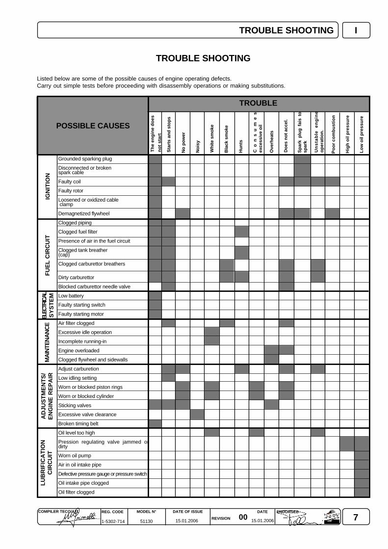
TROUBLE SHOOTING
Listed below are some of the possible causes of engine operating defects.Carry out simple tests before proceeding with disassembly operations or making substitutions.
POSSIBLE CAUSES
TROUBLE
Un
sta
ble
e
ng
ine
op
erat
ion
.
Po
or
com
bu
stio
n
No
isy
No
po
wer
Sta
rts
and
sto
ps
Wh
ite
smo
ke
Bla
ck s
mo
ke
Hu
nts
Co
ns
um
es
exce
ssiv
e o
il
Ove
rhea
ts
Do
es n
ot
acce
l.
Sp
ark
plu
g f
ais
tosp
ark
Hig
h o
il p
ress
ure
Lo
w o
il p
ress
ure
Th
e en
gin
e d
oes
no
t st
art
IGN
ITIO
NF
UE
L C
IRC
UIT
Grounded sparking plug
Disconnected or brokenspark cable
Faulty coil
Faulty rotor
Loosened or oxidized cable clamp
Demagnetized flywheel
Clogged piping
Clogged fuel filter
Presence of air in the fuel circuit
Clogged tank breather(cap)
Clogged carburettor breathers
Dirty carburettor
Blocked carburettor needle valve
Low battery
Faulty starting switch
Faulty starting motor
Air filter clogged
Excessive idle operation
Incomplete running-in
Engine overloaded
Clogged flywheel and sidewalls
Adjust carburetion
Low idling setting
Worn or blocked piston rings
Worn or blocked cylinder
Sticking valves
Excessive valve clearance
Broken timing belt
Oil level too high
Pression regulating valve jammed ordirty
Worn oil pump
Air in oil intake pipe
Defective pressure gauge or pressure switch
Oil intake pipe clogged
Oil filter clogged
ELEC
TRIC
ALS
YS
TE
MM
AIN
TEN
AN
CE
AD
JUS
TM
EN
TS
/E
NG
INE
RE
PA
IRL
UB
RIF
ICA
TIO
NC
IRC
UIT
8 0015.01.2006 15.01.2006
REG. CODE
1-5302-714
MODEL N°
51130
DATE OF ISSUE
REVISION
DATE ENDORSEDCOMPILER TECO/ATL
II WARNING SIGNS - SAFETY INSTRUCTIONS
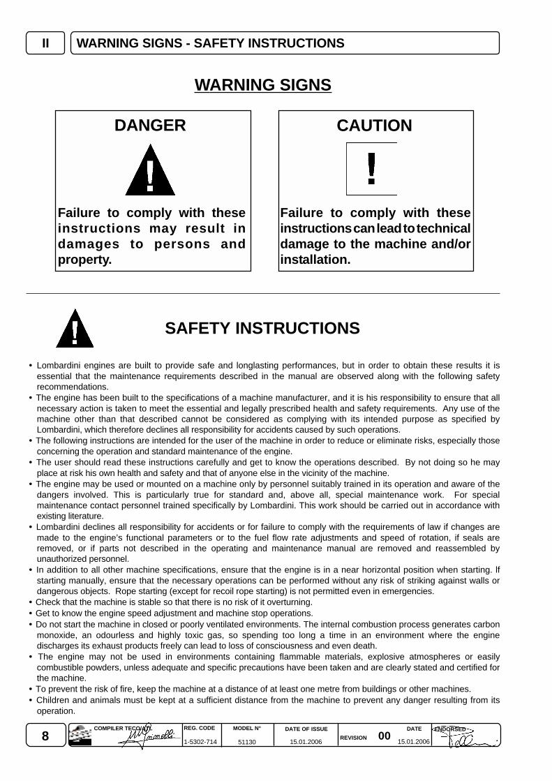
Failure to comply with theseinstructions may result indamages to persons andproperty.
Failure to comply with theseinstructions can lead to technicaldamage to the machine and/orinstallation.
DANGER
WARNING SIGNS
CAUTION
• Lombardini engines are built to provide safe and longlasting performances, but in order to obtain these results it isessential that the maintenance requirements described in the manual are observed along with the following safetyrecommendations.
• The engine has been built to the specifications of a machine manufacturer, and it is his responsibility to ensure that allnecessary action is taken to meet the essential and legally prescribed health and safety requirements. Any use of themachine other than that described cannot be considered as complying with its intended purpose as specified byLombardini, which therefore declines all responsibility for accidents caused by such operations.
• The following instructions are intended for the user of the machine in order to reduce or eliminate risks, especially thoseconcerning the operation and standard maintenance of the engine.
• The user should read these instructions carefully and get to know the operations described. By not doing so he mayplace at risk his own health and safety and that of anyone else in the vicinity of the machine.
• The engine may be used or mounted on a machine only by personnel suitably trained in its operation and aware of thedangers involved. This is particularly true for standard and, above all, special maintenance work. For specialmaintenance contact personnel trained specifically by Lombardini. This work should be carried out in accordance withexisting literature.
• Lombardini declines all responsibility for accidents or for failure to comply with the requirements of law if changes aremade to the engine’s functional parameters or to the fuel flow rate adjustments and speed of rotation, if seals areremoved, or if parts not described in the operating and maintenance manual are removed and reassembled byunauthorized personnel.
• In addition to all other machine specifications, ensure that the engine is in a near horizontal position when starting. lfstarting manually, ensure that the necessary operations can be performed without any risk of striking against walls ordangerous objects. Rope starting (except for recoil rope starting) is not permitted even in emergencies.
• Check that the machine is stable so that there is no risk of it overturning.• Get to know the engine speed adjustment and machine stop operations.• Do not start the machine in closed or poorly ventilated environments. The internal combustion process generates carbon
monoxide, an odourless and highly toxic gas, so spending too long a time in an environment where the enginedischarges its exhaust products freely can lead to loss of consciousness and even death.
• The engine may not be used in environments containing flammable materials, explosive atmospheres or easilycombustible powders, unless adequate and specific precautions have been taken and are clearly stated and certified forthe machine.
• To prevent the risk of fire, keep the machine at a distance of at least one metre from buildings or other machines.• Children and animals must be kept at a sufficient distance from the machine to prevent any danger resulting from its
operation.
SAFETY INSTRUCTIONS
90015.01.2006 15.01.2006
COMPILER TECO/ATL REG. CODE
1-5302-714
MODEL N°
51130
DATE OF ISSUE
REVISION
ENDORSEDDATE
IIWARNING SIGNS - SAFETY INSTRUCTIONS
• Fuel is flammable, so the tank must be filled only when the engine is turned off. Dry carefully any fuel that may havespilled, remove the fuel container and any cloths soaked in fuel or oil, check that any sound-absorbing panels made ofporous material are not soaked with fuel or oil, and make sure that the ground on which the machine is located has notabsorbed fuel or oil.
• To start the engine follow the specific instructions provided in the engine and/or machine operating manual. Do not useauxiliary starting devices not originally installed on the machine (e.g. Startpilot systems which utilise ether etc.)
• Before starting, remove any tools that have been used for carrying out maintenance work to the engine and/or themachine and check that any guards removed have been replaced. In cold climates it is possible to mix kerosene with thediesel fuel to make the engine easier to start. The liquids must be mixed in the tank by pouring in first the kerosene andthen the diesel fuel. Consult Lombardini technical office for mixture proportions. Petrol may not be used because of therisk of it forming flammable vapours.
• During operation the surface of the engine reaches temperatures that may be dangerous. Avoid in particular all contactwith the exhaust system.
• Before carrying out any work on the engine, turn it off and allow it to cool down. Do not perform any operation while theengine is running.
• The liquid cooling circuit is under pressure. Do not carry out any checks before the engine has cooled down, and eventhen open the radiator cap or the expansion tank cautiously. Wear protective clothing and glasses. lf there is an electricfan, do not approach the engine while it is still hot as the fan may come on even when the engine is not running. Cleanthe cooling system with the engine turned off.
• While cleaning the oil bath air filter, check that the oil is disposed of in such a way as not to harm the environment. Anyfiltering sponges in the oil bath air filter should not be soaked with oil. The cyclone pre-filter cup must not be filled with oil.
• Since the oil must be emptied out while the engine is still hot (approx. 80°C), particular care should be taken in order toavoid burns. In any case make sure that oil does not come into contact with your skin because of the health hazardsinvolved.
• Check that the discharged oil, the oil filter and the oil contained in the oil filter are disposed of in such a way as not toharm the environment.
• Close the fuel tank filler cap carefully after each fílling operation. Do not fill the tank right up to the top, but leavesufficient space to allow for any expansion of the fuel.
• Fuel vapours are highly toxic, so fill up only in the open air or in well ventilated environments.• Do not smoke or use naked flames while filling.• Take care when removing the oil filter as it may be hot.• The operations of checking, filling up and replacing the cooling liquid must be carried out with the engine turned off and
cold. Take particular care if liquids containing nitrites are mixed with others not containing these compounds as this maygive rise to the formation of nitrosamines which are a health hazard. The cooling liquid is polluting, so dispose of in amanner that does not damage the environment.
• During operations which involve access to moving parts of the engine and/or removal of the rotary guards, disconnectand insulate the positive cable of the battery so as to prevent accidental short circuits and activation of the starter motor.
• Check the belt tension only when the engine is turned off.• In order to move the engine use exclusively the eyebolts fitted for this purpose by Lombardini. These lifting points are
however not suitable for the entire machine, so in this case use the eyebolts fitted by the manufacturer.
10 0015.01.2006 15.01.2006
REG. CODE
1-5302-714
MODEL N°
51130
DATE OF ISSUE
REVISION
DATE ENDORSEDCOMPILER TECO/ATL
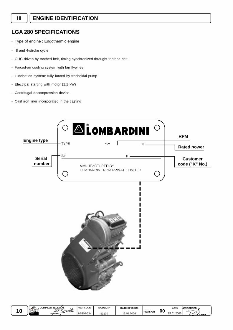
III
Serial number
Customercode ("K" No.)
Engine typeRPM
ENGINE IDENTIFICATION
LGA 280 SPECIFICATIONS
- Type of engine : Endothermic engine
- 8 and 4-stroke cycle
- OHC driven by toothed belt, timing synchronized throught toothed belt
- Forced-air cooling system with fan flywheel
- Lubrication system: fully forced by trochoidal pump
- Electrical starting with motor (1,1 kW)
- Centrifugal decompression device
- Cast iron liner incorporated in the casting
Rated power
110015.01.2006 15.01.2006
COMPILER TECO/ATL REG. CODE
1-5302-714
MODEL N°
51130
DATE OF ISSUE
REVISION
ENDORSEDDATE
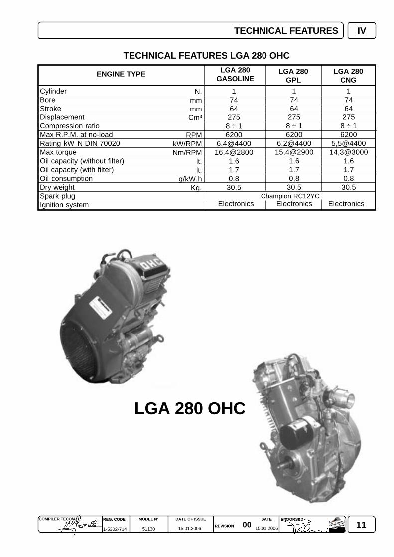
IV
LGA 280 OHC
17464
2758 ÷ 16200
6,4@440016,4@2800
1.61.70.8
30.5
17464
2758 ÷ 16200
6,2@440015,4@2900
1.61.70,8
30.5
17464
2758 ÷ 16200
5,5@440014,3@3000
1.61.70.8
30.5
LGA 280GPL
LGA 280CNG
Champion RC12YC
N.mmmmCm³
RPMkW/RPMNm/RPM
lt.lt.
g/kW.hKg.
TECHNICAL FEATURES
CylinderBoreStrokeDisplacementCompression ratioMax R.P.M. at no-loadRating kW N DIN 70020Max torqueOil capacity (without filter)Oil capacity (with filter)Oil consumptionDry weightSpark plugIgnition system
TECHNICAL FEATURES LGA 280 OHC
ENGINE TYPE LGA 280GASOLINE
Electronics Electronics Electronics
12 0015.01.2006 15.01.2006
REG. CODE
1-5302-714
MODEL N°
51130
DATE OF ISSUE
REVISION
DATE ENDORSEDCOMPILER TECO/ATL
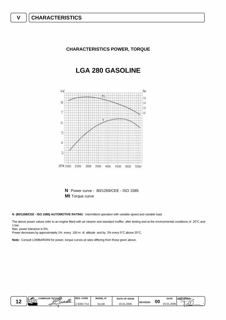
V CHARACTERISTICS
CHARACTERISTICS POWER, TORQUE
N Power curve - 80/1269/CEE - ISO 1585Mt Torque curve
N (80/1269/CEE - ISO 1585) AUTOMOTIVE RATING : Intermittent operation with variable speed and variable load.
The above power values refer to an engine fitted with air cleaner and standard muffler, after testing and at the environmental conditions of 20°C and1 bar.Max. power tolerance is 5%.Power decreases by approximately 1% every 100 m di altitude and by 2% every 5°C above 20°C.
Note: Consult LOMBARDINI for power, torque curves at rates differing from those given above.
LGA 280 GASOLINE
130015.01.2006 15.01.2006
COMPILER TECO/ATL REG. CODE
1-5302-714
MODEL N°
51130
DATE OF ISSUE
REVISION
ENDORSEDDATE
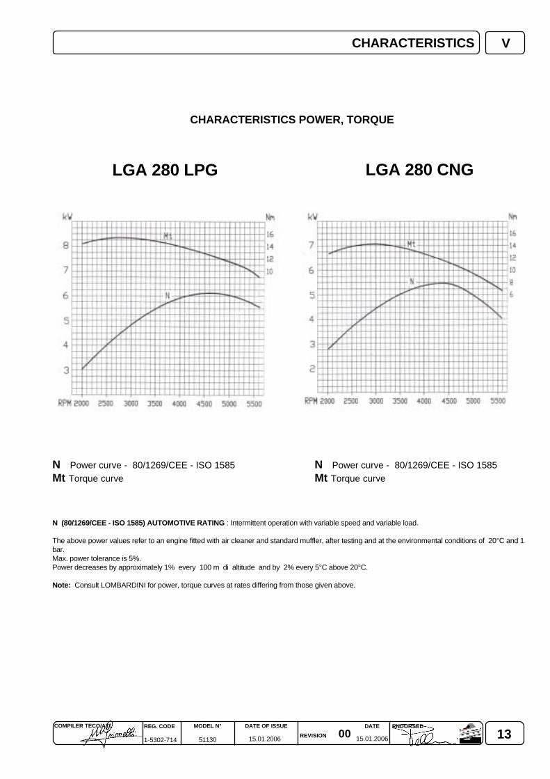
V
LGA 280 LPG LGA 280 CNG
CHARACTERISTICS
CHARACTERISTICS POWER, TORQUE
N Power curve - 80/1269/CEE - ISO 1585 N Power curve - 80/1269/CEE - ISO 1585Mt Torque curve Mt Torque curve
N (80/1269/CEE - ISO 1585) AUTOMOTIVE RATING : Intermittent operation with variable speed and variable load.
The above power values refer to an engine fitted with air cleaner and standard muffler, after testing and at the environmental conditions of 20°C and 1bar.Max. power tolerance is 5%.Power decreases by approximately 1% every 100 m di altitude and by 2% every 5°C above 20°C.
Note: Consult LOMBARDINI for power, torque curves at rates differing from those given above.
14 0015.01.2006 15.01.2006
REG. CODE
1-5302-714
MODEL N°
51130
DATE OF ISSUE
REVISION
DATE ENDORSEDCOMPILER TECO/ATL
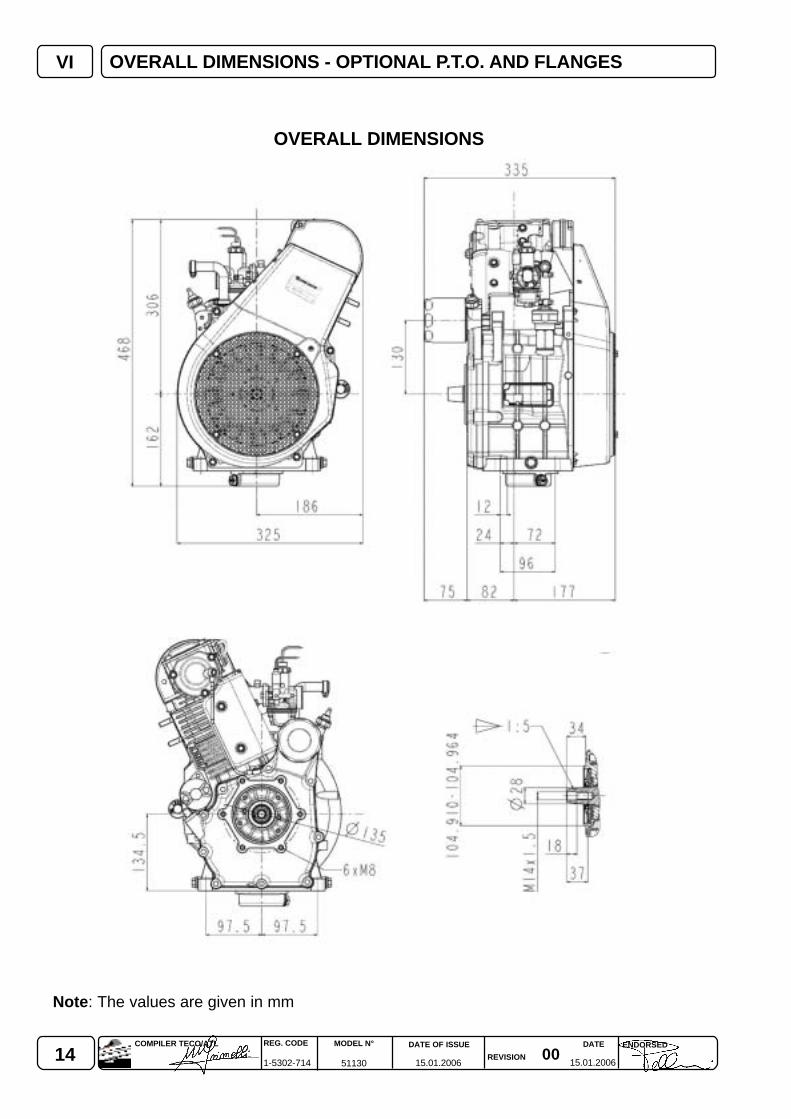
VI OVERALL DIMENSIONS - OPTIONAL P.T.O. AND FLANGES
OVERALL DIMENSIONS
Note: The values are given in mm

150015.01.2006 15.01.2006
COMPILER TECO/ATL REG. CODE
1-5302-714
MODEL N°
51130
DATE OF ISSUE
REVISION
ENDORSEDDATE
VII
1 10 20 30 40 50 60 70 80 90 100
Failure to carry out the operations described in the table may lead to technical damage to the machineand/or system
MAINTENANCE - RECOMMENDED OIL - FUELS AND LUBRICANTS
(*) Once removed, the timing belt must be replaced, even if it has not reached its scheduled change interval.Keep the same maintenance intervals above 100.000 km.
Even if the set mileage has not been reached, replace the following :- engine oil after one year- timing belt after four years
To avoid explosions or fire outbreaks, do not smoke or use naked flames during the operations.Fuel vapours are highly toxic. Only carry out the operations outdoors or in a well-ventilated place.Keep your face well away from the plug to prevent harmful vapours from being inhaled. Dispose of fuel inthe correct way and do not litter as it is highly polluting
PROCEDURE ELEMENTFREQUENCY x 1.000 Km
Every 1.000 Km
CHECK
ENGINE OIL LEVEL
COOLING SYSTEM
AIR CLEANER
FUEL PIPES AND UNIONS
EXHAUST SYSTEM
CANDELE -SPARK PLUGS
VALVE CLEARANCE
ENGINE OIL
LUBE OIL FILTER
FUEL FILTER
AIR CLEANER CARTRIDGE
SPARK PLUGS
TIMING BELT (*)
Oil filter replacement.
MAINTENANCE EXTRAORDINARY AFTER THE FIRST 1.000 Km
Engine oil replacement.
REPLACEMENT
ORDINARY MAINTENANCE FOR ENGINES LGA 280 OHC
Every 5.000 Km
16 0015.01.2006 15.01.2006
REG. CODE
1-5302-714
MODEL N°
51130
DATE OF ISSUE
REVISION
DATE ENDORSEDCOMPILER TECO/ATL
VII
FUEL
Use PREMIUM gasoline or UNLEADED PREMIUM gasoline of the type used in cars. Use of other types of fuelcould damage the engine.The octane rating of the fuel must be higher than 95 to prevent difficult starting.Do not use old, dirty gasoline or oil-gasoline, water-gasoline mixtures since this would cause serious engine faults.
The engine could be damaged if allowed to operate with insufficient oil quantity .The lubrication oil influences the performances and life of the engine in an incredible way.Use of an inferior quality oil or failure to regularly change the oil will increase the risk of piston seizure, may make thecompression rings jam and will lead to rapid wear on the cylinder liner, the bearings and all other moving parts. Engine lifewill also be notably reduced.Oil viscosity must suit the ambient temperature in which the engine operates.
Old oil can cause skin cancer if repeatedly left in contact with the skin and for long periods of time. If contact with the oilis inevitable, you are advised to thoroughly wash your hands with soap and water as soon as possible.Appropriate protective gloves etc should be wore during this operation.Old oil is highly polluting and must be disposed of in the correct way. Do not litter.
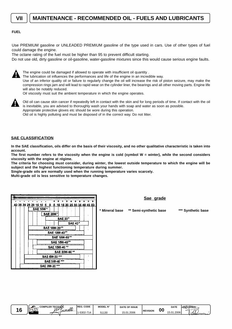
SAE CLASSIFICATION
In the SAE classification, oils differ on the basis of their viscosity, and no other qualitative characteristic is taken intoaccount.The first number refers to the viscosity when the engine is cold (symbol W = winter), while the second considersviscosity with the engine at régime.The criteria for choosing must consider, during winter, the lowest outside temperature to which the engine will besubject and the highest functioning temperature during summer.Single-grade oils are normally used when the running temperature varies scarcely.Multi-grade oil is less sensitive to temperature changes.
Sae grade
* Mineral base ** Semi-synthetic base *** Synthetic base
MAINTENANCE - RECOMMENDED OIL - FUELS AND LUBRICANTS
170015.01.2006 15.01.2006
COMPILER TECO/ATL REG. CODE
1-5302-714
MODEL N°
51130
DATE OF ISSUE
REVISION
ENDORSEDDATE
VII
123456789012345678901234567890
12345678901234567890123456781234567890123456789012345678123456789012345678901234567812345678901234567890123456781234567890123456789012345678
12345678901234567891234567890123456789123456789012345678912345678901234567891234567890123456789
123456789123456789123456789
CF CE CD CC CB CA SA SB SC SD SE SF SG
L - 2104 D / EL - 46152 B / C / D / E
SHAPI SJ SLCH-4 CG-4 CF-4 CF-2
MIL
1,7
1,6
LGA 280
AGIP SINT2000 15W40/50
API SJ/CFACEA A3-98 B3-98MIL-L-46152 D/E.
MAINTENANCE - RECOMMENDED OIL - FUELS AND LUBRICANTS
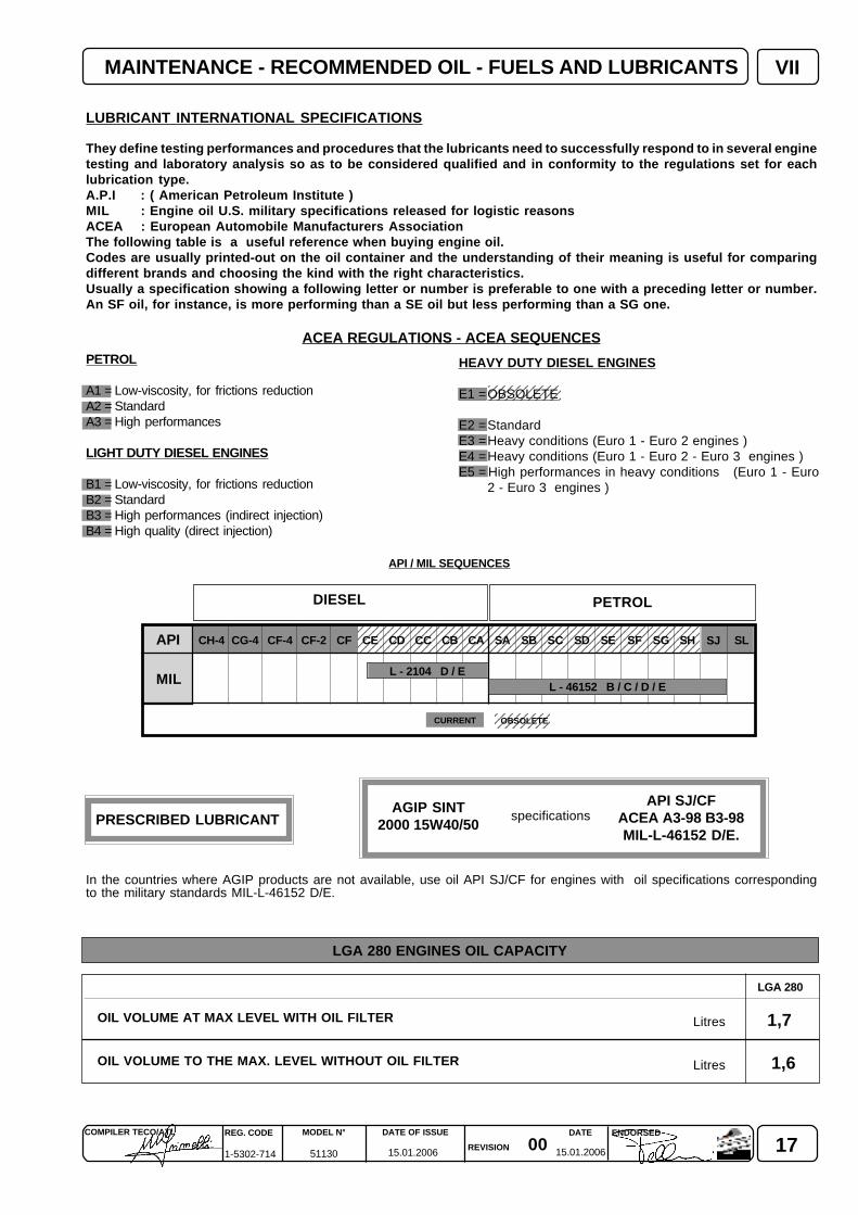
LUBRICANT INTERNATIONAL SPECIFICATIONS
They define testing performances and procedures that the lubricants need to successfully respond to in several enginetesting and laboratory analysis so as to be considered qualified and in conformity to the regulations set for eachlubrication type.A.P.I : ( American Petroleum Institute )MIL : Engine oil U.S. military specifications released for logistic reasonsACEA : European Automobile Manufacturers AssociationThe following table is a useful reference when buying engine oil.Codes are usually printed-out on the oil container and the understanding of their meaning is useful for comparingdifferent brands and choosing the kind with the right characteristics.Usually a specification showing a following letter or number is preferable to one with a preceding letter or number.An SF oil, for instance, is more performing than a SE oil but less performing than a SG one.
ACEA REGULATIONS - ACEA SEQUENCES
API / MIL SEQUENCES
PETROL
A1 = Low-viscosity, for frictions reductionA2 = StandardA3 = High performances
LIGHT DUTY DIESEL ENGINES
B1 = Low-viscosity, for frictions reductionB2 = StandardB3 = High performances (indirect injection)B4 = High quality (direct injection)
DIESEL PETROL
OBSOLETECURRENT
HEAVY DUTY DIESEL ENGINES
E1 =OBSOLETE
E2 =StandardE3 =Heavy conditions (Euro 1 - Euro 2 engines )E4 =Heavy conditions (Euro 1 - Euro 2 - Euro 3 engines )E5 = High performances in heavy conditions (Euro 1 - Euro
2 - Euro 3 engines )
OIL VOLUME AT MAX LEVEL WITH OIL FILTER
OIL VOLUME TO THE MAX. LEVEL WITHOUT OIL FILTER
Litres
Litres
specifications
In the countries where AGIP products are not available, use oil API SJ/CF for engines with oil specifications correspondingto the military standards MIL-L-46152 D/E.
PRESCRIBED LUBRICANT
LGA 280 ENGINES OIL CAPACITY
18 0015.01.2006 15.01.2006
REG. CODE
1-5302-714
MODEL N°
51130
DATE OF ISSUE
REVISION
DATE ENDORSEDCOMPILER TECO/ATL
1
2
3
4
VIII
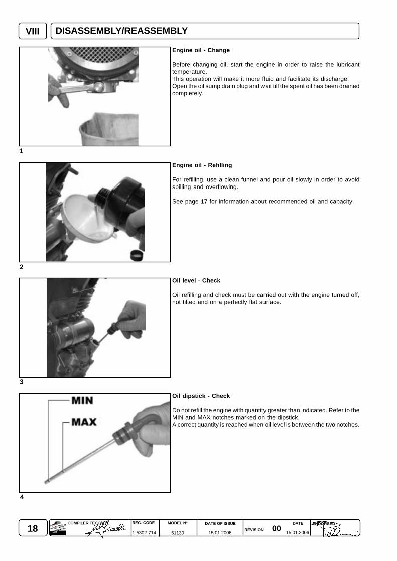
Engine oil - Change
Before changing oil, start the engine in order to raise the lubricanttemperature.This operation will make it more fluid and facilitate its discharge.Open the oil sump drain plug and wait till the spent oil has been drainedcompletely.
Engine oil - Refilling
For refilling, use a clean funnel and pour oil slowly in order to avoidspilling and overflowing.
See page 17 for information about recommended oil and capacity.
Oil level - Check
Oil refilling and check must be carried out with the engine turned off,not tilted and on a perfectly flat surface.
Oil dipstick - Check
Do not refill the engine with quantity greater than indicated. Refer to theMIN and MAX notches marked on the dipstick.A correct quantity is reached when oil level is between the two notches.
DISASSEMBLY/REASSEMBLY
190015.01.2006 15.01.2006
COMPILER TECO/ATL REG. CODE
1-5302-714
MODEL N°
51130
DATE OF ISSUE
REVISION
ENDORSEDDATE
VIII
5
6 7
DISASSEMBLY/REASSEMBLY
DISASSEMBLY AND REASSEMBLY
Beside disassembly and reassembly operations, this chapter also includes checks, setting up, dimensions, repairs and runninginstructions.It is necessary to use LOMBARDINI original spare parts for a correct repair.
General information for a correct repair
Any change to the intake or exhaust systems (e.g. air filter or muffler type, hose length and diameter, etc.) also impliesa carburetion adjustment. Lombardini will not be held responsible for engine malfunctions and damages arising fromany such changes.
For a safe and reliable operation, strictly keep to the instructions detailed in the maintenance manual as well as to the informationbelow:
- Lock the machine before disassembling the engine.- Disconnect battery cables if engine is equipped with an electrical starting system.- Always use suitable tools, in order to avoid damaging engine parts.- To separate coupled parts, use plastic hammers or punches only.- During disassembly, mark the parts that are not provided with reference points.- Clean the disassembled parts with gasoline and compressed air.- Always replace gaskets, oil sealing rings, washers and locknuts;- Before reassembling, lubricate all moving parts and mating surfaces.- When tightening screws, keep to the torque specified.
During repairs, when compressed air is used, always wear goggles.
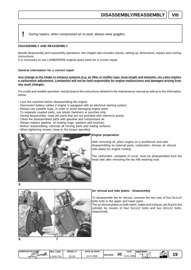
Engine preparation
After removing oil, place engine on a workbench and startdisassembling its external parts: carburettor, shroud, air shroudside plates for engine cooling.
The carburettor, complete of curve, must be disassembled from thehead side after removing the two M8 retaining nuts.
Air shroud and side plates - Disassembly
To disassemble the air shroud, unscrew the two sets of four 6x1x12bolts both in the upper and lower parts.The air shroud plates on both sides, intake and exhaust, are fixed to thecylinder by means of four 6x1x12 bolts and two 6x1x12 bolts,respectively.
20 0015.01.2006 15.01.2006
REG. CODE
1-5302-714
MODEL N°
51130
DATE OF ISSUE
REVISION
DATE ENDORSEDCOMPILER TECO/ATL
9
VIII
10
8
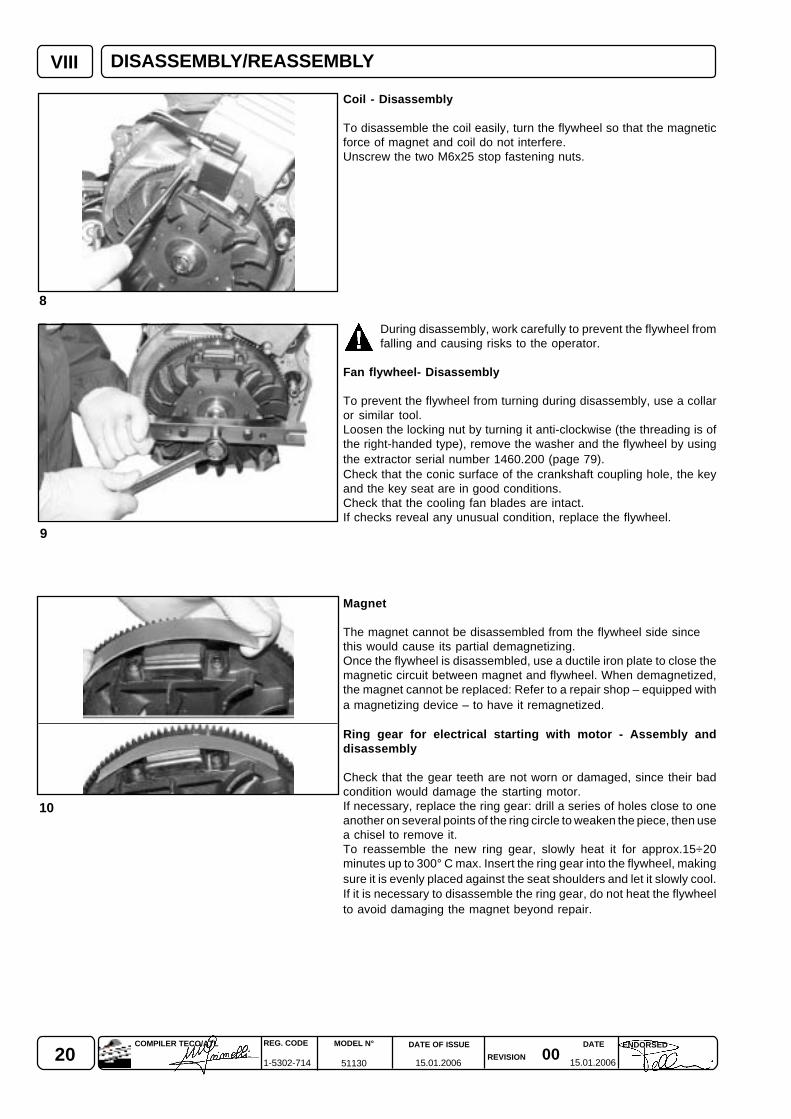
Coil - Disassembly
To disassemble the coil easily, turn the flywheel so that the magneticforce of magnet and coil do not interfere.Unscrew the two M6x25 stop fastening nuts.
During disassembly, work carefully to prevent the flywheel fromfalling and causing risks to the operator.
Fan flywheel- Disassembly
To prevent the flywheel from turning during disassembly, use a collaror similar tool.Loosen the locking nut by turning it anti-clockwise (the threading is ofthe right-handed type), remove the washer and the flywheel by usingthe extractor serial number 1460.200 (page 79).Check that the conic surface of the crankshaft coupling hole, the keyand the key seat are in good conditions.Check that the cooling fan blades are intact.If checks reveal any unusual condition, replace the flywheel.
Magnet
The magnet cannot be disassembled from the flywheel side sincethis would cause its partial demagnetizing.Once the flywheel is disassembled, use a ductile iron plate to close themagnetic circuit between magnet and flywheel. When demagnetized,the magnet cannot be replaced: Refer to a repair shop – equipped witha magnetizing device – to have it remagnetized.
Ring gear for electrical starting with motor - Assembly anddisassembly
Check that the gear teeth are not worn or damaged, since their badcondition would damage the starting motor.If necessary, replace the ring gear: drill a series of holes close to oneanother on several points of the ring circle to weaken the piece, then usea chisel to remove it.To reassemble the new ring gear, slowly heat it for approx.15÷20minutes up to 300° C max. Insert the ring gear into the flywheel, makingsure it is evenly placed against the seat shoulders and let it slowly cool.If it is necessary to disassemble the ring gear, do not heat the flywheelto avoid damaging the magnet beyond repair.
DISASSEMBLY/REASSEMBLY
210015.01.2006 15.01.2006
COMPILER TECO/ATL REG. CODE
1-5302-714
MODEL N°
51130
DATE OF ISSUE
REVISION
ENDORSEDDATE
11
VIII
12
13
14
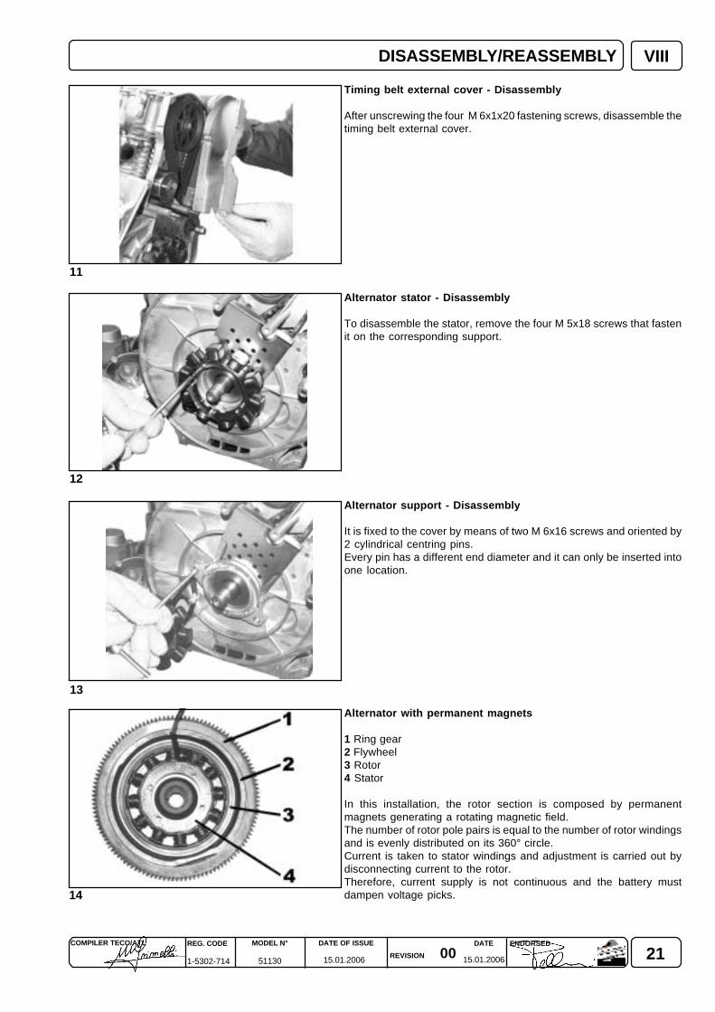
Timing belt external cover - Disassembly
After unscrewing the four M 6x1x20 fastening screws, disassemble thetiming belt external cover.
Alternator stator - Disassembly
To disassemble the stator, remove the four M 5x18 screws that fastenit on the corresponding support.
Alternator support - Disassembly
It is fixed to the cover by means of two M 6x16 screws and oriented by2 cylindrical centring pins.Every pin has a different end diameter and it can only be inserted intoone location.
Alternator with permanent magnets
1 Ring gear2 Flywheel3 Rotor4 Stator
In this installation, the rotor section is composed by permanentmagnets generating a rotating magnetic field.The number of rotor pole pairs is equal to the number of rotor windingsand is evenly distributed on its 360° circle.Current is taken to stator windings and adjustment is carried out bydisconnecting current to the rotor.Therefore, current supply is not continuous and the battery mustdampen voltage picks.
DISASSEMBLY/REASSEMBLY
22 0015.01.2006 15.01.2006
REG. CODE
1-5302-714
MODEL N°
51130
DATE OF ISSUE
REVISION
DATE ENDORSEDCOMPILER TECO/ATL
VIII
17
15
18
16
1
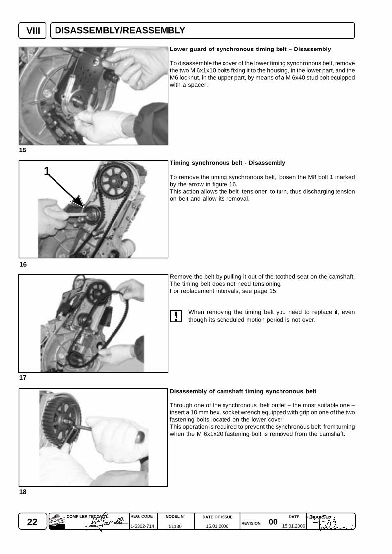
Lower guard of synchronous timing belt – Disassembly
To disassemble the cover of the lower timing synchronous belt, removethe two M 6x1x10 bolts fixing it to the housing, in the lower part, and theM6 locknut, in the upper part, by means of a M 6x40 stud bolt equippedwith a spacer.
Timing synchronous belt - Disassembly
To remove the timing synchronous belt, loosen the M8 bolt 1 markedby the arrow in figure 16.This action allows the belt tensioner to turn, thus discharging tensionon belt and allow its removal.
Remove the belt by pulling it out of the toothed seat on the camshaft.The timing belt does not need tensioning.For replacement intervals, see page 15.
When removing the timing belt you need to replace it, eventhough its scheduled motion period is not over.
Disassembly of camshaft timing synchronous belt
Through one of the synchronous belt outlet – the most suitable one –insert a 10 mm hex. socket wrench equipped with grip on one of the twofastening bolts located on the lower coverThis operation is required to prevent the synchronous belt from turningwhen the M 6x1x20 fastening bolt is removed from the camshaft.
DISASSEMBLY/REASSEMBLY
230015.01.2006 15.01.2006
COMPILER TECO/ATL REG. CODE
1-5302-714
MODEL N°
51130
DATE OF ISSUE
REVISION
ENDORSEDDATE
VIII
19
20
21
22
2 3
1
P.M.S.
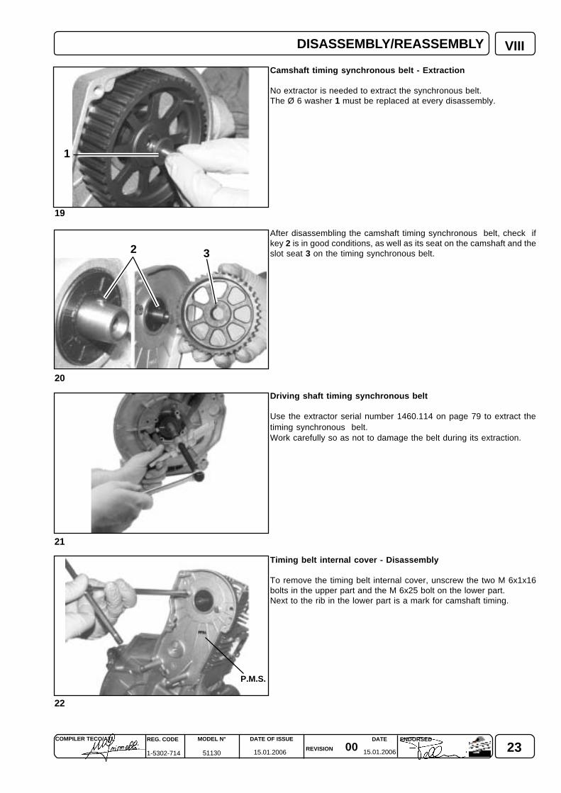
Camshaft timing synchronous belt - Extraction
No extractor is needed to extract the synchronous belt.The Ø 6 washer 1 must be replaced at every disassembly.
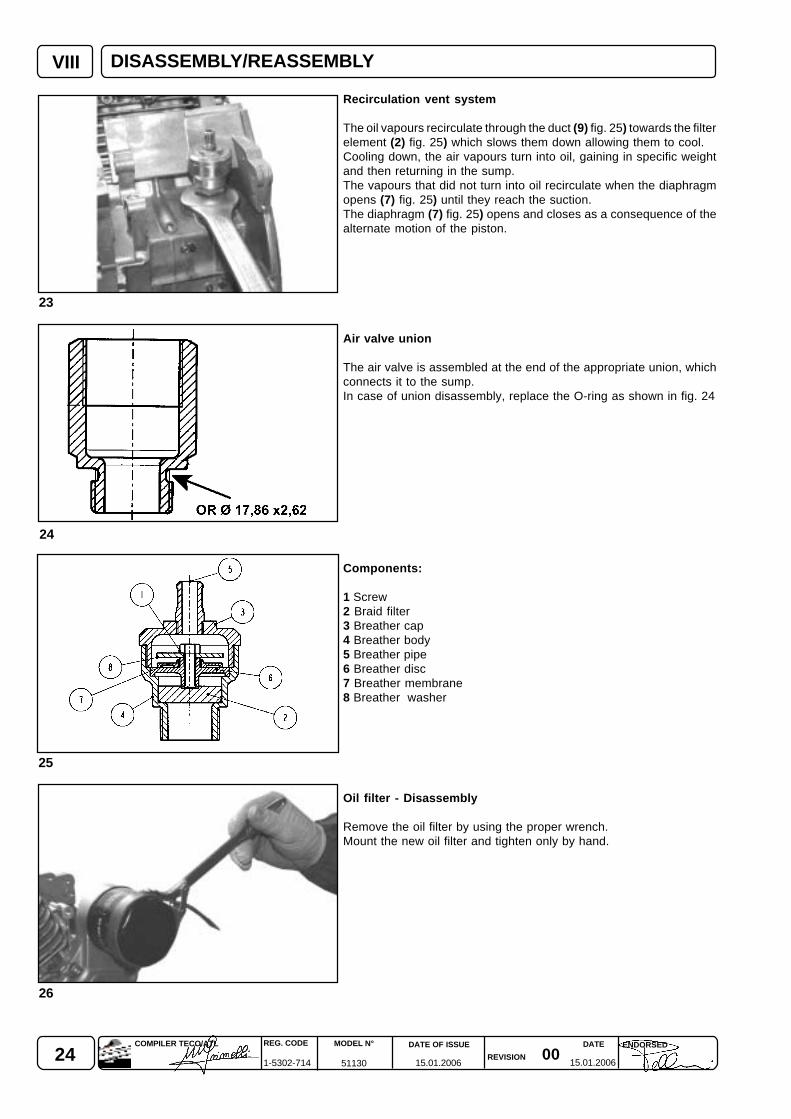
After disassembling the camshaft timing synchronous belt, check ifkey 2 is in good conditions, as well as its seat on the camshaft and theslot seat 3 on the timing synchronous belt.
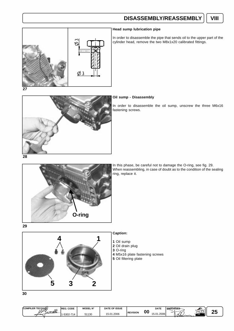
Driving shaft timing synchronous belt
Use the extractor serial number 1460.114 on page 79 to extract thetiming synchronous belt.Work carefully so as not to damage the belt during its extraction.
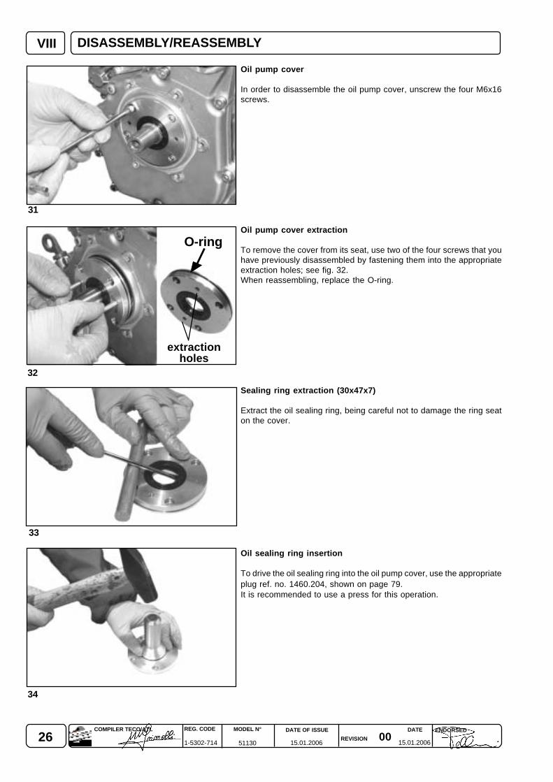
Timing belt internal cover - Disassembly
To remove the timing belt internal cover, unscrew the two M 6x1x16bolts in the upper part and the M 6x25 bolt on the lower part.Next to the rib in the lower part is a mark for camshaft timing.
DISASSEMBLY/REASSEMBLY
24 0015.01.2006 15.01.2006
REG. CODE
1-5302-714
MODEL N°
51130
DATE OF ISSUE
REVISION
DATE ENDORSEDCOMPILER TECO/ATL
VIII
25
23
26
24
Recirculation vent system
The oil vapours recirculate through the duct (9) fig. 25) towards the filterelement (2) fig. 25) which slows them down allowing them to cool.Cooling down, the air vapours turn into oil, gaining in specific weightand then returning in the sump.The vapours that did not turn into oil recirculate when the diaphragmopens (7) fig. 25) until they reach the suction.The diaphragm (7) fig. 25) opens and closes as a consequence of thealternate motion of the piston.
Air valve union
The air valve is assembled at the end of the appropriate union, whichconnects it to the sump.In case of union disassembly, replace the O-ring as shown in fig. 24
Components:
1 Screw2 Braid filter3 Breather cap4 Breather body5 Breather pipe6 Breather disc7 Breather membrane8 Breather washer
Oil filter - Disassembly
Remove the oil filter by using the proper wrench.Mount the new oil filter and tighten only by hand.
DISASSEMBLY/REASSEMBLY
250015.01.2006 15.01.2006
COMPILER TECO/ATL REG. CODE
1-5302-714
MODEL N°
51130
DATE OF ISSUE
REVISION
ENDORSEDDATE
VIII
27
28
29
30
1
25 3
4
DISASSEMBLY/REASSEMBLY
Head sump lubrication pipe
In order to disassemble the pipe that sends oil to the upper part of thecylinder head, remove the two M8x1x20 calibrated fittings.
Oil sump - Disassembly
In order to disassemble the oil sump, unscrew the three M6x16fastening screws.
In this phase, be careful not to damage the O-ring, see fig. 29.When reassembling, in case of doubt as to the condition of the sealingring, replace it.
Caption:
1 Oil sump2 Oil drain plug3 O-ring4 M5x16 plate fastening screws5 Oil filtering plate
O-ring
26 0015.01.2006 15.01.2006
REG. CODE
1-5302-714
MODEL N°
51130
DATE OF ISSUE
REVISION
DATE ENDORSEDCOMPILER TECO/ATL
VIII
32
31
33
34
Oil pump cover
In order to disassemble the oil pump cover, unscrew the four M6x16screws.
Oil pump cover extraction
To remove the cover from its seat, use two of the four screws that youhave previously disassembled by fastening them into the appropriateextraction holes; see fig. 32.When reassembling, replace the O-ring.
Sealing ring extraction (30x47x7)
Extract the oil sealing ring, being careful not to damage the ring seaton the cover.
Oil sealing ring insertion
To drive the oil sealing ring into the oil pump cover, use the appropriateplug ref. no. 1460.204, shown on page 79.It is recommended to use a press for this operation.
DISASSEMBLY/REASSEMBLY
O-ring
extractionholes
270015.01.2006 15.01.2006
COMPILER TECO/ATL REG. CODE
1-5302-714
MODEL N°
51130
DATE OF ISSUE
REVISION
ENDORSEDDATE
VIII
37
36
35
38
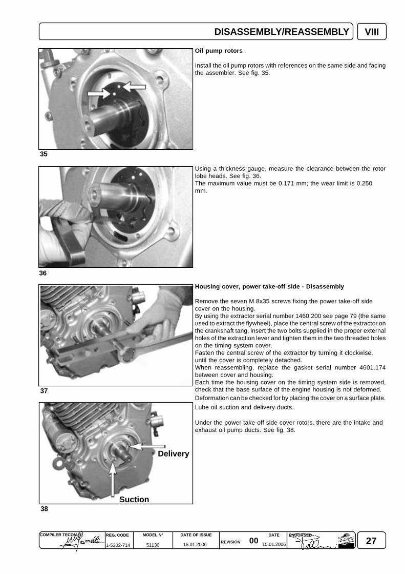
Oil pump rotors
Install the oil pump rotors with references on the same side and facingthe assembler. See fig. 35.
Using a thickness gauge, measure the clearance between the rotorlobe heads. See fig. 36.The maximum value must be 0.171 mm; the wear limit is 0.250mm.
Housing cover, power take-off side - Disassembly
Remove the seven M 8x35 screws fixing the power take-off sidecover on the housing.By using the extractor serial number 1460.200 see page 79 (the sameused to extract the flywheel), place the central screw of the extractor onthe crankshaft tang, insert the two bolts supplied in the proper externalholes of the extraction lever and tighten them in the two threaded holeson the timing system cover.Fasten the central screw of the extractor by turning it clockwise,until the cover is completely detached.When reassembling, replace the gasket serial number 4601.174between cover and housing.Each time the housing cover on the timing system side is removed,check that the base surface of the engine housing is not deformed.Deformation can be checked for by placing the cover on a surface plate.
Lube oil suction and delivery ducts.
Under the power take-off side cover rotors, there are the intake andexhaust oil pump ducts. See fig. 38.
DISASSEMBLY/REASSEMBLY
Suction
Delivery

28 0015.01.2006 15.01.2006
REG. CODE
1-5302-714
MODEL N°
51130
DATE OF ISSUE
REVISION
DATE ENDORSEDCOMPILER TECO/ATL
VIII
41
40
42
39
12345
DISASSEMBLY/REASSEMBLY
Power take-off side cover - Disassembly
In order to extract the cover, turn it 45° as shown in the figure, so as toallow the oil suction pipe to pass through housing overall dimensions.Each time the cover is removed, check that the base surface of theengine housing is not deformed.Deformation can be checked for by placing the cover on a surface plate.
Oil pressure regulating valve
The oil pressure regulating valve is located inside the power take-offside cover.
When disassembling the oil pressure regulating valve, thoroughlyclean all its components before reassembling it.
Oil pressure regulating valve components
Caption
1 Snap ring2 Spring housing cup3 Flat washer4 Calibrated spring5 Plunger
290015.01.2006 15.01.2006
COMPILER TECO/ATL REG. CODE
1-5302-714
MODEL N°
51130
DATE OF ISSUE
REVISION
ENDORSEDDATE
45
44
VIII
43
A
DISASSEMBLY/REASSEMBLY
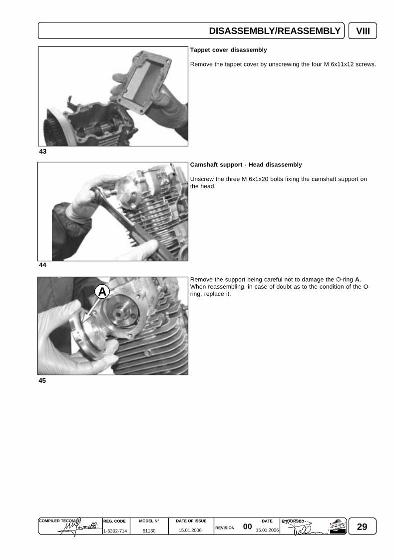
Tappet cover disassembly
Remove the tappet cover by unscrewing the four M 6x11x12 screws.
Camshaft support - Head disassembly
Unscrew the three M 6x1x20 bolts fixing the camshaft support onthe head.
Remove the support being careful not to damage the O-ring A.When reassembling, in case of doubt as to the condition of the O-ring, replace it.
30 0015.01.2006 15.01.2006
REG. CODE
1-5302-714
MODEL N°
51130
DATE OF ISSUE
REVISION
DATE ENDORSEDCOMPILER TECO/ATL
VIII
49
48
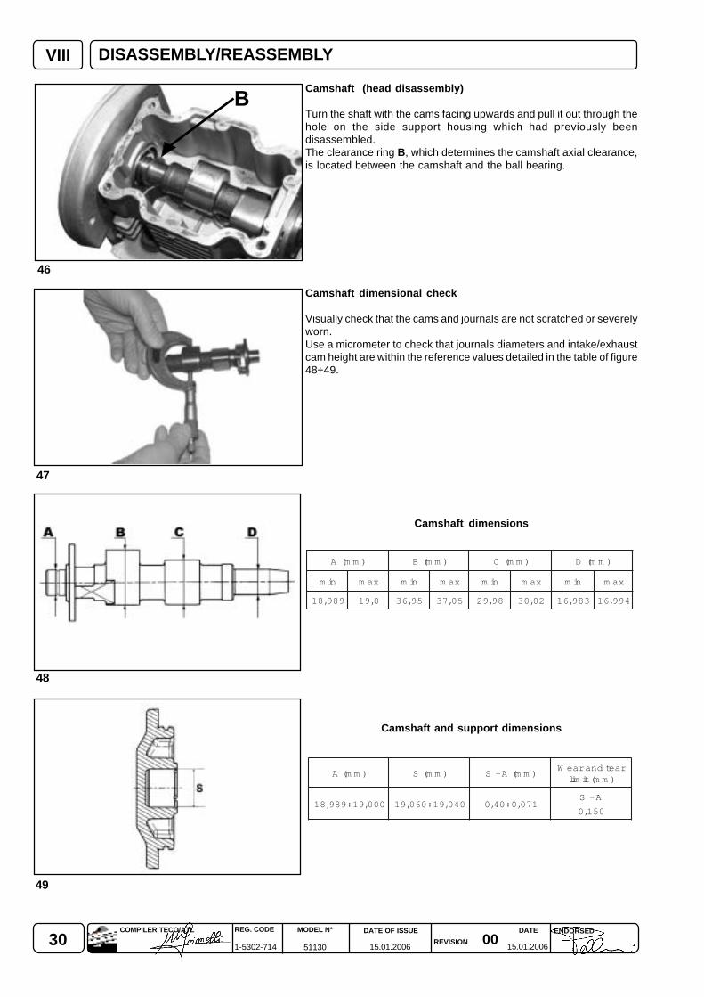
)mm(A )mm(B )mm(C )mm(D
nim xam nim xam nim xam nim xam
989,81 0,91 59,63 50,73 89,92 20,03 389,61 499,61
46
47
B
)mm(A )mm(S )mm(A-SraetdnaraeW
)mm(timil
000,91÷989,81 040,91÷060,91 170,0÷04,0A-S
051,0
Camshaft (head disassembly)
Turn the shaft with the cams facing upwards and pull it out through thehole on the side support housing which had previously beendisassembled.The clearance ring B, which determines the camshaft axial clearance,is located between the camshaft and the ball bearing.
Camshaft dimensional check
Visually check that the cams and journals are not scratched or severelyworn.Use a micrometer to check that journals diameters and intake/exhaustcam height are within the reference values detailed in the table of figure48÷49.
Camshaft dimensions
Camshaft and support dimensions
DISASSEMBLY/REASSEMBLY

310015.01.2006 15.01.2006
COMPILER TECO/ATL REG. CODE
1-5302-714
MODEL N°
51130
DATE OF ISSUE
REVISION
ENDORSEDDATE
VIII
44
50
DISASSEMBLY/REASSEMBLY
Legend
S = piston at top dead centrel = piston at bottom dead centreααααα = intake valve openβββββ = intake valve closedγγγγγ = exhaust valve openδδδδδ = exhaust valve closed
Timing diagram
The values on the diagram refer to 1 mm-clearance between tappets and valves, when the engine is cold.
32 0015.01.2006 15.01.2006
REG. CODE
1-5302-714
MODEL N°
51130
DATE OF ISSUE
REVISION
DATE ENDORSEDCOMPILER TECO/ATL
53
VIII
52
51
14
3 2
1 4
3 2
54 55
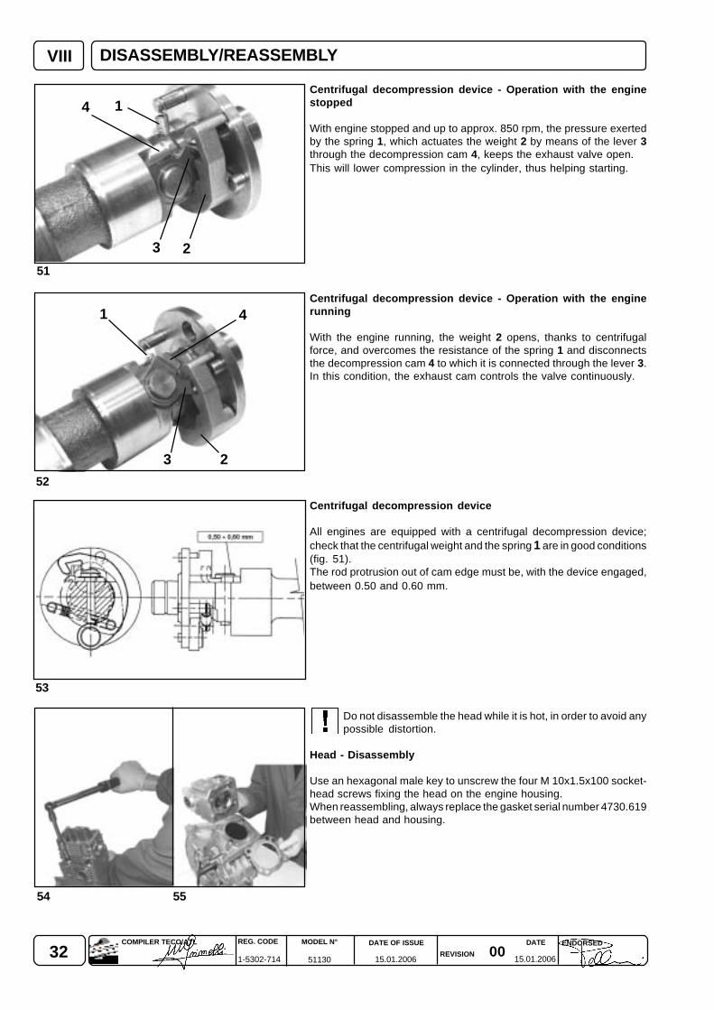
Centrifugal decompression device - Operation with the enginestopped
With engine stopped and up to approx. 850 rpm, the pressure exertedby the spring 1, which actuates the weight 2 by means of the lever 3through the decompression cam 4, keeps the exhaust valve open.This will lower compression in the cylinder, thus helping starting.
Centrifugal decompression device - Operation with the enginerunning
With the engine running, the weight 2 opens, thanks to centrifugalforce, and overcomes the resistance of the spring 1 and disconnectsthe decompression cam 4 to which it is connected through the lever 3.In this condition, the exhaust cam controls the valve continuously.
Centrifugal decompression device
All engines are equipped with a centrifugal decompression device;check that the centrifugal weight and the spring 1 are in good conditions(fig. 51).The rod protrusion out of cam edge must be, with the device engaged,between 0.50 and 0.60 mm.
Do not disassemble the head while it is hot, in order to avoid anypossible distortion.
Head - Disassembly
Use an hexagonal male key to unscrew the four M 10x1.5x100 socket-head screws fixing the head on the engine housing.When reassembling, always replace the gasket serial number 4730.619between head and housing.
DISASSEMBLY/REASSEMBLY
330015.01.2006 15.01.2006
COMPILER TECO/ATL REG. CODE
1-5302-714
MODEL N°
51130
DATE OF ISSUE
REVISION
ENDORSEDDATE
VIII
58
59
56
57
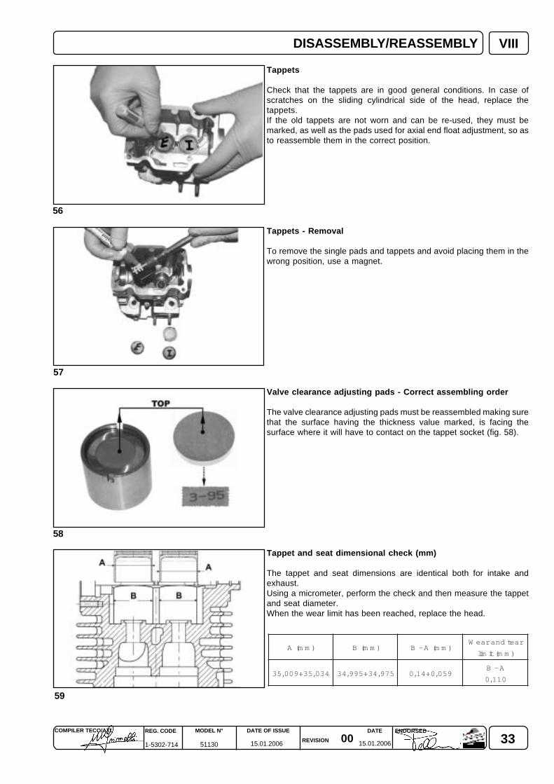
Tappets
Check that the tappets are in good general conditions. In case ofscratches on the sliding cylindrical side of the head, replace thetappets.If the old tappets are not worn and can be re-used, they must bemarked, as well as the pads used for axial end float adjustment, so asto reassemble them in the correct position.
Tappets - Removal
To remove the single pads and tappets and avoid placing them in thewrong position, use a magnet.
Valve clearance adjusting pads - Correct assembling order
The valve clearance adjusting pads must be reassembled making surethat the surface having the thickness value marked, is facing thesurface where it will have to contact on the tappet socket (fig. 58).
Tappet and seat dimensional check (mm)
The tappet and seat dimensions are identical both for intake andexhaust.Using a micrometer, perform the check and then measure the tappetand seat diameter.When the wear limit has been reached, replace the head.
)mm(A )mm(B )mm(A-BraetdnaraeW
timil )mm(
430,53÷900,53 579,43÷599,43 950,0÷41,0A-B
011,0
DISASSEMBLY/REASSEMBLY
34 0015.01.2006 15.01.2006
REG. CODE
1-5302-714
MODEL N°
51130
DATE OF ISSUE
REVISION
DATE ENDORSEDCOMPILER TECO/ATL
60
61
62
VIII
63
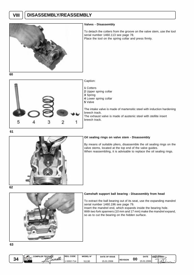
Valves - Disassembly
To detach the cotters from the groove on the valve stem, use the toolserial number 1460.113 see page 78.Place the tool on the spring collar and press firmly.
Caption:
1 Cotters2 Upper spring collar3 Spring4 Lower spring collar5 Valve
The intake valve is made of martensitic steel with induction hardeningbreech track.The exhaust valve is made of austenic steel with stellite insertbreech track.
Oil sealing rings on valve stem - Disassembly
By means of suitable pliers, disassemble the oil sealing rings on thevalve stems, located at the top end of the valve guides.When reassembling, it is advisable to replace the oil sealing rings.
Camshaft support ball bearing - Disassembly from head
To extract the ball bearing out of its seat, use the expanding mandrelserial number 1460.196 see page 79.Insert the mandrel end, which expands inside the bearing hole.With two fork spanners (10 mm and 17 mm) make the mandrel expand,so as to cut the bearing on the hidden surface.
DISASSEMBLY/REASSEMBLY
350015.01.2006 15.01.2006
COMPILER TECO/ATL REG. CODE
1-5302-714
MODEL N°
51130
DATE OF ISSUE
REVISION
ENDORSEDDATE
VIII
67
64
66
65
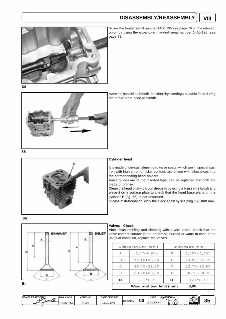
Screw the beater serial number 1460.195 see page 79 on the relevantunion by using the expanding mandrel serial number 1460.196 seepage 79.
Have the head slide in both directions by exerting a suitable force duringthe stroke from head to handle.
Cylinder head
It is made of die-cast aluminium; valve seats, which are in special castiron with high chrome-nickel content, are driven with allowances intothe corresponding head holders.Valve guides are of the inserted type, can be replaced and both aremade of bronze.Clean the head of any carbon deposits by using a brass wire brush andplace it on a surface plate to check that the head base plane on thecylinder P (fig. 66) is not deformed.In case of deformation, work the piece again by scalping 0.25 mm max.
Valves - CheckAfter disassembling and cleaning with a wire brush, check that thevalve contact surface is not deformed, burned or worn; in case of anunusual condition, replace the valves.
)mm(evlavtsuahxE )mm(evlavtelnI
A 559,6÷79,6 E 569,6÷789,6
B 09,35÷01,45 F 07,46÷05,46
C 09,82÷07,82 G 09,23÷07,23
D 09,08÷07,08 H 09,08÷07,08
ααααα '51±°121 ααααα '51±°121
09,6)mm(timilraetdnaraeW
DISASSEMBLY/REASSEMBLY
36 0015.01.2006 15.01.2006
REG. CODE
1-5302-714
MODEL N°
51130
DATE OF ISSUE
REVISION
DATE ENDORSEDCOMPILER TECO/ATL
70
VIII
68
69
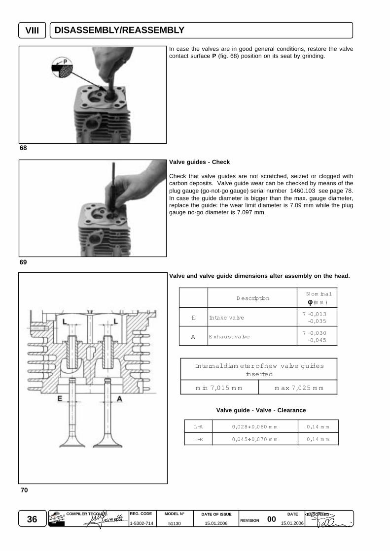
A-L mm060,0÷820,0 mm41,0
E-L mm070,0÷540,0 mm41,0
In case the valves are in good general conditions, restore the valvecontact surface P (fig. 68) position on its seat by grinding.
Valve guides - Check
Check that valve guides are not scratched, seized or clogged withcarbon deposits. Valve guide wear can be checked by means of theplug gauge (go-not-go gauge) serial number 1460.103 see page 78.In case the guide diameter is bigger than the max. gauge diameter,replace the guide: the wear limit diameter is 7.09 mm while the pluggauge no-go diameter is 7.097 mm.
Valve and valve guide dimensions after assembly on the head.
Valve guide - Valve - Clearance
noitpircseDlanimoN
φφφφφ )mm(
E evlavekatnI310,0-7530,0-
A evlavtsuahxE030,0-7540,0-
sediugevlavwenforetemaidlanretnIdetresni
mm510,7nim mm520,7xam
DISASSEMBLY/REASSEMBLY
370015.01.2006 15.01.2006
COMPILER TECO/ATL REG. CODE
1-5302-714
MODEL N°
51130
DATE OF ISSUE
REVISION
ENDORSEDDATE
VIII
71
73
74
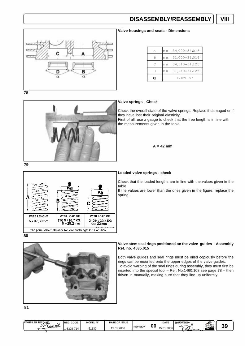
A 04,73÷03,73mm
B 540,7÷530,7mm
C 810,21÷000,21mm
D 02,6÷08,5mm
E 58,9÷57,9mm
72
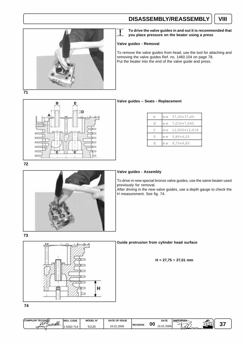
To drive the valve guides in and out it is recommended thatyou place pressure on the beater using a press
Valve guides - Removal
To remove the valve guides from head, use the tool for attaching andremoving the valve guides Ref. no. 1460.104 on page 78.Put the beater into the end of the valve guide and press.
Valve guides – Seats - Replacement
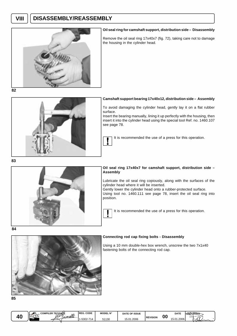
Valve guides - Assembly
To drive in new special bronze valve guides, use the same beater usedpreviously for removal.After driving in the new valve guides, use a depth gauge to check theH measurement. See fig. 74.
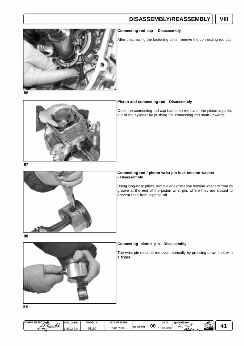
Guide protrusion from cylinder head surface
H = 27,75 ÷ 27,01 mm
DISASSEMBLY/REASSEMBLY

38 0015.01.2006 15.01.2006
REG. CODE
1-5302-714
MODEL N°
51130
DATE OF ISSUE
REVISION
DATE ENDORSEDCOMPILER TECO/ATL
VIII
75
76
77
Valve seats
The valve seats are made of special sintered steel with a highquantity of nickel chrome, to make them more resistant to wear andcombustion heat. To regrind them, use conical cutters with angle 120° intake - exhaust.
NOTE: Prolonged use of the engine and the continuous hammering of thevalve seats at high temperatures causes hardening of the track P(fig. 68 page 36), and makes manual milling impossible. It istherefore necessary to remove the hardened surface layer using agrindstone on a valve seat grinder. The final adjustment can thenbe performed manually using the cutter mentioned above (fig. 75).Grinding the valve seats causes the widening of the valve seatsupport track R. If R is wider than 2,2mm, mount an upturnedcutter and lower surface Q (fig. 75) until R measures: 1.5 ÷ 1.8 mm.
The final adjustment of the valve into its seat must be performed bysprinkling fine emery compound onto the seat and rotating the valveback and forth with a light pressure, until the surfaces in figure 56 areperfectly settled.Next, carefully rinse the valve and seat using petroland spray with compressed air to get rid of any remaining emerycompound or shavings. Next, carefully rinse the valve and seat usingpetrol and spray with compressed air to get rid of any remaining emerycompound or shavings.this is not the case, continue milling until theright conditions are reached.
Next, carefully rinse the valve and seat using petrol and spray withcompressed air to get rid of any remaining emery compound orshavings.
To check the grip between the valve and its seat after grinding, proceedas follows:
1) Place the valve on its head with spring and stop collars.2) Pour a few drops of diesel or oil around the valve head.3) Blow compressed air through the exhaust/intake duct, taking care to plug off the edges of the duct to avoid air leaks (fig. 77).
If air bubbles form between the valve and its seat, remove the valve and adjust by milling the seat. This adjustment can be testedby jogging the valve in its seat, first pushing upwards, then letting it drop freely. If the bounce is significant and uniform, evenwhen the valve is slowly twisted round completely, it means that the adjustment is correct. If this is not the case, continue millinguntil the right conditions are reached.
If the valve seat needs changing, proceed as follows:
1) Using a 2÷3 mm bit, drill holes into the valve seat and finish off with a chisel without damaging the housing.2) Remove the seat.3) Heat the head to 160° - 180° C.4) Position the new seat using a press.
Operations of this kind should preferably be performed in specialist workshops or grinding centres.
DISASSEMBLY/REASSEMBLY
390015.01.2006 15.01.2006
COMPILER TECO/ATL REG. CODE
1-5302-714
MODEL N°
51130
DATE OF ISSUE
REVISION
ENDORSEDDATE
VIII
78
79
80
81
A 610,43÷000,43mm
B 610,13÷000,13mm
C 521,43÷041,43mm
D 521,13÷041,13mm
ααααα '51±°021
Valve housings and seats - Dimensions
Valve springs - Check
Check the overall state of the valve springs. Replace if damaged or ifthey have lost their original elasticity.First of all, use a gauge to check that the free length is in line withthe measurements given in the table.
A = 42 mm
Loaded valve springs - check
Check that the loaded lengths are in line with the values given in thetableIf the values are lower than the ones given in the figure, replace thespring.
Valve stem seal rings positioned on the valve guides – AssemblyRef. no. 4535.015
Both valve guides and seal rings must be oiled copiously before therings can be mounted onto the upper edges of the valve guides.To avoid warping of the seal rings during assembly, they must first beinserted into the special tool – Ref. No.1460.108 see page 78 – thendriven in manually, making sure that they line up uniformly.
DISASSEMBLY/REASSEMBLY
40 0015.01.2006 15.01.2006
REG. CODE
1-5302-714
MODEL N°
51130
DATE OF ISSUE
REVISION
DATE ENDORSEDCOMPILER TECO/ATL
83
84
85
82
VIII
Oil seal ring for camshaft support, distribution side – Disassembly
Remove the oil seal ring 17x40x7 (fig. 72), taking care not to damagethe housing in the cylinder head.
Camshaft support bearing 17x40x12, distribution side – Assembly
To avoid damaging the cylinder head, gently lay it on a flat rubbersurface.Insert the bearing manually, lining it up perfectly with the housing, theninsert it into the cylinder head using the special tool Ref. no. 1460.107see page 78.
It is recommended the use of a press for this operation.
Oil seal ring 17x40x7 for camshaft support, distribution side –Assembly
Lubricate the oil seal ring copiously, along with the surfaces of thecylinder head where it will be inserted.Gently lower the cylinder head onto a rubber-protected surface.Using tool no. 1460.111 see page 78, insert the oil seal ring intoposition.
It is recommended the use of a press for this operation.
Connecting rod cap fixing bolts - Disassembly
Using a 10 mm double-hex box wrench, unscrew the two 7x1x40fastening bolts of the connecting rod cap.
DISASSEMBLY/REASSEMBLY
410015.01.2006 15.01.2006
COMPILER TECO/ATL REG. CODE
1-5302-714
MODEL N°
51130
DATE OF ISSUE
REVISION
ENDORSEDDATE
86
VIII
89
87
88
Connecting rod cap - Disassembly
After unscrewing the fastening bolts, remove the connecting rod cap.
Piston and connecting rod - Disassembly
Once the connecting rod cap has been removed, the piston is pulledout of the cylinder by pushing the connecting rod shaft upwards.
Connecting rod / piston wrist pin lock tension washer- Disassembly
Using long-nose pliers, remove one of the two tension washers from itsgroove at the end of the piston wrist pin, where they are slotted toprevent then from slipping off.
Connecting piston pin - Disassembly
The wrist pin must be removed manually by pressing down on it witha finger.
DISASSEMBLY/REASSEMBLY
42 0015.01.2006 15.01.2006
REG. CODE
1-5302-714
MODEL N°
51130
DATE OF ISSUE
REVISION
DATE ENDORSEDCOMPILER TECO/ATL
92
91
90
VIII
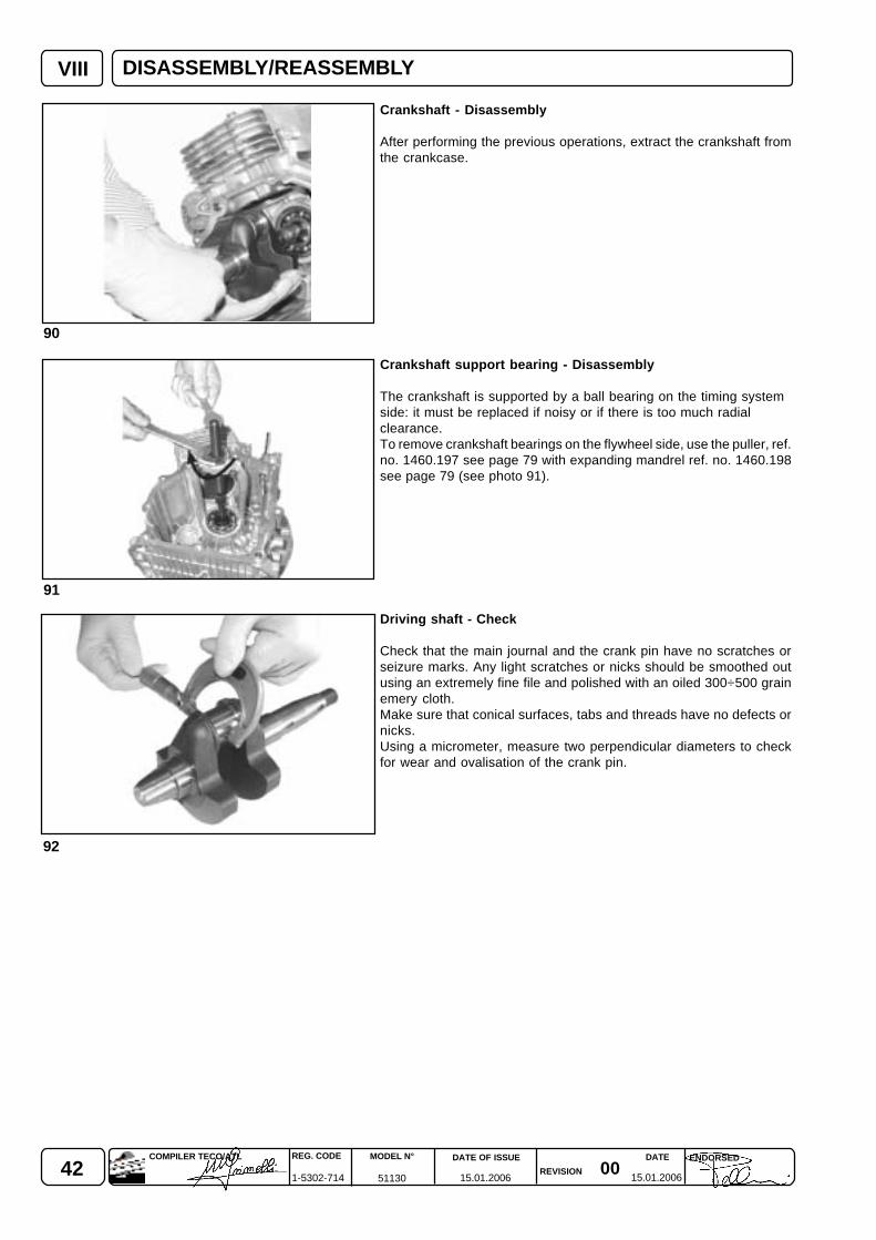
Crankshaft - Disassembly
After performing the previous operations, extract the crankshaft fromthe crankcase.
Crankshaft support bearing - Disassembly
The crankshaft is supported by a ball bearing on the timing systemside: it must be replaced if noisy or if there is too much radialclearance.To remove crankshaft bearings on the flywheel side, use the puller, ref.no. 1460.197 see page 79 with expanding mandrel ref. no. 1460.198see page 79 (see photo 91).
Driving shaft - Check
Check that the main journal and the crank pin have no scratches orseizure marks. Any light scratches or nicks should be smoothed outusing an extremely fine file and polished with an oiled 300÷500 grainemery cloth.Make sure that conical surfaces, tabs and threads have no defects ornicks.Using a micrometer, measure two perpendicular diameters to checkfor wear and ovalisation of the crank pin.
DISASSEMBLY/REASSEMBLY
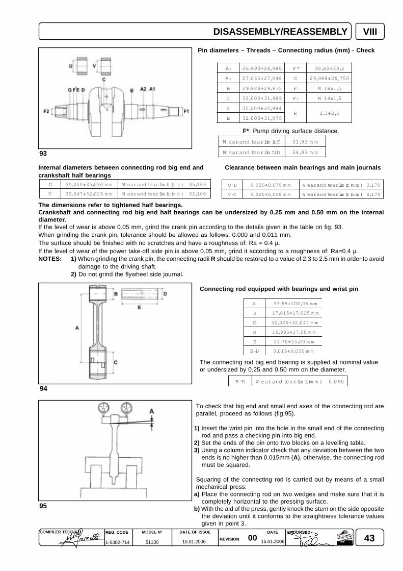
430015.01.2006 15.01.2006
COMPILER TECO/ATL REG. CODE
1-5302-714
MODEL N°
51130
DATE OF ISSUE
REVISION
ENDORSEDDATE
93
VIII
95
94
A 1 089,62÷399,62 *F 5,03÷06,03
A 2 840,72÷530,72 G 057,92÷889,92
B 579,92÷889,92 F1 5,1x81M
C 989,13÷000,23 F2 5,1x41M
D 489,43÷000,53R 5,2÷3,2
E 579,13÷000,23
A mm50,001÷59,99
B mm520,71÷510,71
C mm740,23÷520,23
D mm00,71÷599,61
E mm00,55÷07,45
D-B mm030,0÷510,0
CtimilraetdnaraeW mm39,13
DitmilraetdnaraeW mm39,43
U mm030,53÷050,53 001,53)mm(timilraetdnaraeW
V mm520,23÷740,23 001,23)mm(timilraetdnaraeW
D-U mm570,0÷930,0 071,0)mm(timilraetdnaraeW
C-V mm850,0÷520,0 071,0)mm(timilraetdnaraeW
Pin diameters – Threads – Connecting radius (mm) - Check
F*: Pump driving surface distance.
Internal diameters between connecting rod big end and Clearance between main bearings and main journalscrankshaft half bearings
The dimensions refer to tightened half bearings.Crankshaft and connecting rod big end half bearings can be undersized by 0.25 mm and 0.50 mm on the internaldiameter.If the level of wear is above 0.05 mm, grind the crank pin according to the details given in the table on fig. 93.When grinding the crank pin, tolerance should be allowed as follows: 0.000 and 0.011 mm.The surface should be finished with no scratches and have a roughness of: Ra = 0.4 µ.If the level of wear of the power take-off side pin is above 0.05 mm, grind it according to a roughness of: Ra=0.4 µ.NOTES: 1) When grinding the crank pin, the connecting radii R should be restored to a value of 2.3 to 2.5 mm in order to avoid
damage to the driving shaft.2) Do not grind the flywheel side journal.
Connecting rod equipped with bearings and wrist pin
The connecting rod big end bearing is supplied at nominal valueor undersized by 0.25 and 0.50 mm on the diameter.
To check that big end and small end axes of the connecting rod areparallel, proceed as follows (fig.95).
1) Insert the wrist pin into the hole in the small end of the connectingrod and pass a checking pin into big end.
2) Set the ends of the pin onto two blocks on a levelling table.3) Using a column indicator check that any deviation between the two
ends is no higher than 0.015mm (A), otherwise, the connecting rodmust be squared.
Squaring of the connecting rod is carried out by means of a smallmechanical press:
a) Place the connecting rod on two wedges and make sure that it iscompletely horizontal to the pressing surface.
b) With the aid of the press, gently knock the stem on the side oppositethe deviation until it conforms to the straightness tolerance valuesgiven in point 3.
D-B 060,0)mm(timilraetdnaraeW
DISASSEMBLY/REASSEMBLY
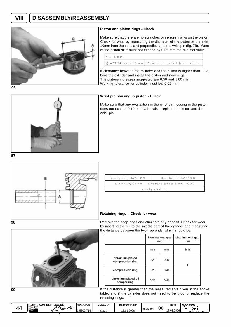
44 0015.01.2006 15.01.2006
REG. CODE
1-5302-714
MODEL N°
51130
DATE OF ISSUE
REVISION
DATE ENDORSEDCOMPILER TECO/ATL
VIII
98
97
96
99
Piston and piston rings - Check
Make sure that there are no scratches or seizure marks on the piston.Check for wear by measuring the diameter of the piston at the skirt,10mm from the base and perpendicular to the wrist pin (fig. 78). Wearof the piston skirt must not exceed by 0.05 mm the minimal value.
If clearance between the cylinder and the piston is higher than 0.23,bore the cylinder and install the piston and new rings.The pistons increases suggested are 0.50 and 1.00 mm.Working tolerance for cylinder must be: 0.02 mm
Wrist pin housing in piston - Check
Make sure that any ovalization in the wrist pin housing in the pistondoes not exceed 0.10 mm. Otherwise, replace the piston and thewrist pin.
Retaining rings – Check for wear
Remove the snap rings and eliminate any deposit. Check for wearby inserting them into the middle part of the cylinder and measuringthe distance between the two free ends, which should be:
If the distance is greater than the measurements given in the abovetable, and if the cylinder does not need to be ground, replace theretaining rings.
pagdnelanimoNmm
pagdnetimilxaMmm
nim xam timil
detalpmuimorhcgnirnoisserpmoc 02,0 04,0
1
gnirnoisserpmoc 02,0 04,0
liodetalpmuimorhcgnirreparcs 02,0 04,0
mm01=A
mm559,37÷549,37=Q 598,37)mm(timilraetdnaraeW
mm899,61÷100,71=A mm599,61÷899,61=B
001,0)mm(timilraetdnaraeWmm600,0÷0=B-A
8,0tnemngilasiM
DISASSEMBLY/REASSEMBLY
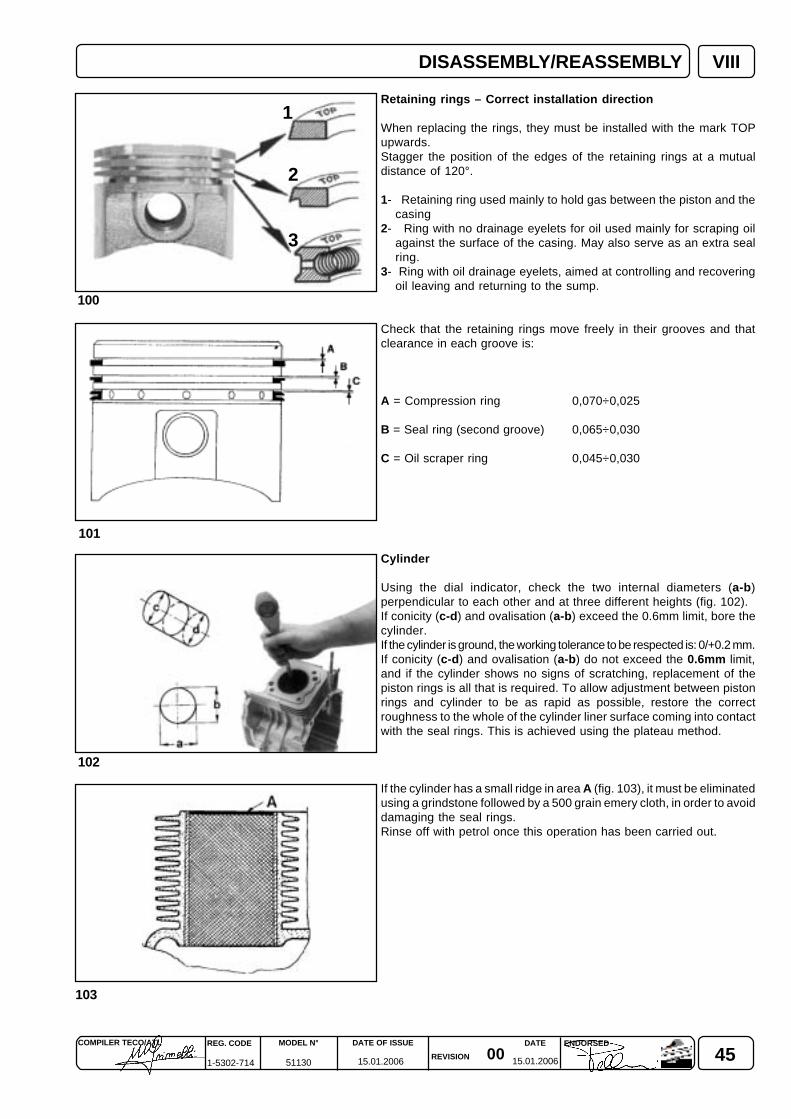
450015.01.2006 15.01.2006
COMPILER TECO/ATL REG. CODE
1-5302-714
MODEL N°
51130
DATE OF ISSUE
REVISION
ENDORSEDDATE
102
101
100
VIII
103
1
2
3
Retaining rings – Correct installation direction
When replacing the rings, they must be installed with the mark TOPupwards.Stagger the position of the edges of the retaining rings at a mutualdistance of 120°.
1- Retaining ring used mainly to hold gas between the piston and thecasing
2- Ring with no drainage eyelets for oil used mainly for scraping oilagainst the surface of the casing. May also serve as an extra sealring.
3- Ring with oil drainage eyelets, aimed at controlling and recoveringoil leaving and returning to the sump.
Check that the retaining rings move freely in their grooves and thatclearance in each groove is:
A = Compression ring 0,070÷0,025
B = Seal ring (second groove) 0,065÷0,030
C = Oil scraper ring 0,045÷0,030
Cylinder
Using the dial indicator, check the two internal diameters (a-b)perpendicular to each other and at three different heights (fig. 102).If conicity (c-d) and ovalisation (a-b) exceed the 0.6mm limit, bore thecylinder.If the cylinder is ground, the working tolerance to be respected is: 0/+0.2 mm.If conicity (c-d) and ovalisation (a-b) do not exceed the 0.6mm limit,and if the cylinder shows no signs of scratching, replacement of thepiston rings is all that is required. To allow adjustment between pistonrings and cylinder to be as rapid as possible, restore the correctroughness to the whole of the cylinder liner surface coming into contactwith the seal rings. This is achieved using the plateau method.
If the cylinder has a small ridge in area A (fig. 103), it must be eliminatedusing a grindstone followed by a 500 grain emery cloth, in order to avoiddamaging the seal rings.Rinse off with petrol once this operation has been carried out.
DISASSEMBLY/REASSEMBLY
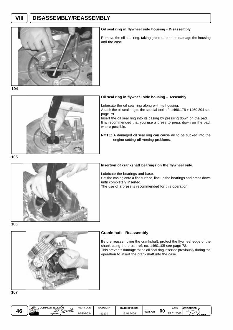
46 0015.01.2006 15.01.2006
REG. CODE
1-5302-714
MODEL N°
51130
DATE OF ISSUE
REVISION
DATE ENDORSEDCOMPILER TECO/ATL
VIII
106
105
104
107
Oil seal ring in flywheel side housing - Disassembly
Remove the oil seal ring, taking great care not to damage the housingand the case.
Oil seal ring in flywheel side housing – Assembly
Lubricate the oil seal ring along with its housing.Attach the oil seal ring to the special tool ref. 1460.176 + 1460.204 seepage 79.Insert the oil seal ring into its casing by pressing down on the pad.It is recommended that you use a press to press down on the pad,where possible.
NOTE: A damaged oil seal ring can cause air to be sucked into theengine setting off venting problems.
Insertion of crankshaft bearings on the flywheel side.
Lubricate the bearings and base.Set the casing onto a flat surface, line up the bearings and press downuntil completely inserted.The use of a press is recommended for this operation.
Crankshaft - Reassembly
Before reassembling the crankshaft, protect the flywheel edge of theshank using the brush ref. no. 1460.105 see page 78.This prevents damage to the oil seal ring inserted previously during theoperation to insert the crankshaft into the case.
DISASSEMBLY/REASSEMBLY

470015.01.2006 15.01.2006
COMPILER TECO/ATL REG. CODE
1-5302-714
MODEL N°
51130
DATE OF ISSUE
REVISION
ENDORSEDDATE
110
109
108
111
VIII
�
�
Before installing, lubricate: the wrist pin, the small end and bigend of the connecting rod, the piston, the cylinder.
Piston and Connecting Rod
Follow the instructions below to install the piston in accordance withtheir correct installation direction:
- the connecting rod must be installed on the crankshaft with the markson the connecting rod big end facing the same side (see fig. 108 and109).
- couple the piston to the connecting rod using the wrist pin, pressinggently with thumb. Insert the two stop pins and make sure they arewell positioned in their seats in the piston;
- assemble the piston rings with the sign “top” pointing upwards,stagger the position of the edges of the piston rings at a mutualdistance of 120° (fig. 100 see page 45);
- insert the piston into the cylinder with the arrow above the crownpointing towards the exhaust fig. 108. Use any normal ring clampavailable on the market to tighten the piston rings;
- assemble the connecting rod cap (the mark should be placed on thesame side as shown on the connecting rod shaft), fasten theconnecting rod screws (fig. 110) by using a torque wrench to: 26 Nm.
Cap on the connecting rod big end - Assembly
Tighten the bolts on the cap of the connecting rod big end using atorque wrench to 26 Nm.It is recommended the use of a series of short twists before the finaltightening.
Note: it is advisable to replace the connecting rod bolts whenever theyare removed.
Power take-off side cover - Assembly
After sealing the two contact surfaces using a seal, mount thecasing cover.The screws must be tightened to the torque of 23.5 Nm.
DISASSEMBLY/REASSEMBLY
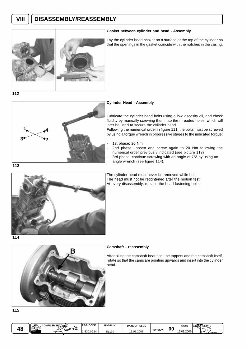
48 0015.01.2006 15.01.2006
REG. CODE
1-5302-714
MODEL N°
51130
DATE OF ISSUE
REVISION
DATE ENDORSEDCOMPILER TECO/ATL
B
VIII
114
113
112
115
1
2
4
3
Gasket between cylinder and head - Assembly
Lay the cylinder head basket on a surface at the top of the cylinder sothat the openings in the gasket coincide with the notches in the casing.
Cylinder Head - Assembly
Lubricate the cylinder head bolts using a low viscosity oil, and checkfluidity by manually screwing them into the threaded holes, which willlater be used to secure the cylinder head.Following the numerical order in figure 111, the bolts must be screwedby using a torque wrench in progressive stages to the indicated torque:
- 1st phase: 20 Nm- 2nd phase: loosen and screw again to 20 Nm following the
numerical order previously indicated (see picture 113)- 3rd phase: continue screwing with an angle of 75° by using an
angle wrench (see figure 114).
The cylinder head must never be removed while hot.The head must not be retightened after the motion test.At every disassembly, replace the head fastening bolts.
Camshaft - reassembly
After oiling the camshaft bearings, the tappets and the camshaft itself,rotate so that the cams are pointing upwards and insert into the cylinderhead.
DISASSEMBLY/REASSEMBLY
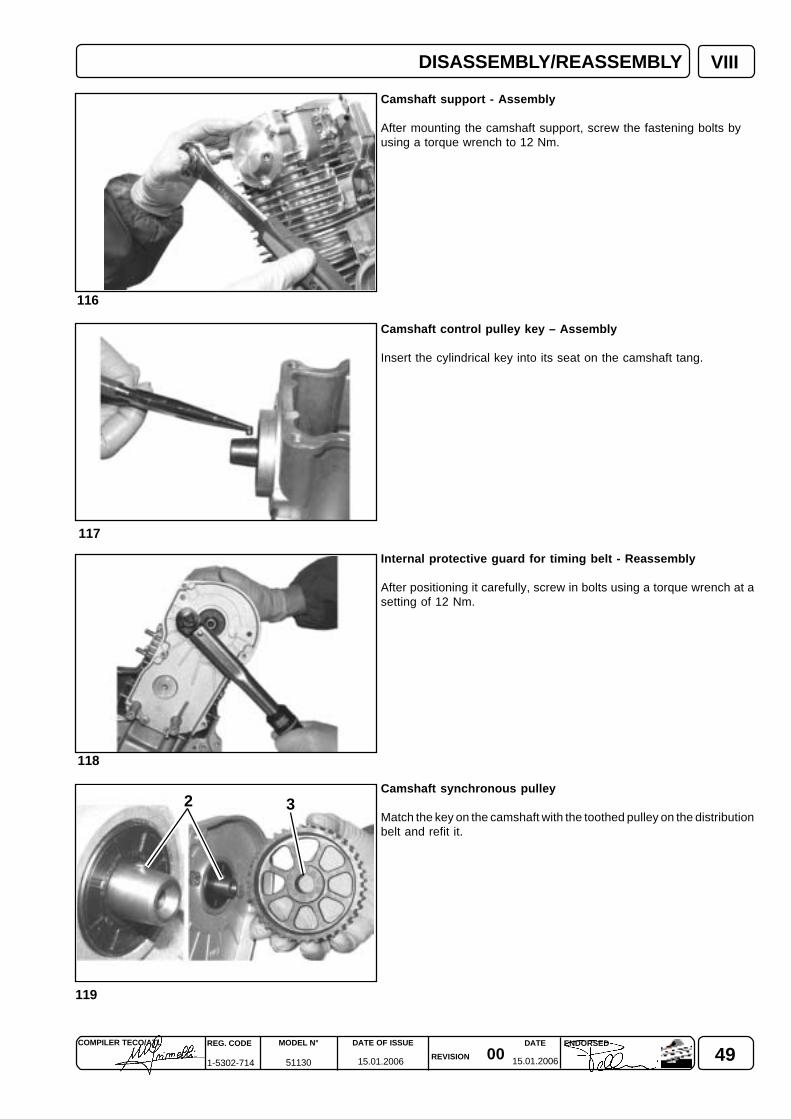
490015.01.2006 15.01.2006
COMPILER TECO/ATL REG. CODE
1-5302-714
MODEL N°
51130
DATE OF ISSUE
REVISION
ENDORSEDDATE
VIII
118
116
117
119
32
Camshaft support - Assembly
After mounting the camshaft support, screw the fastening bolts byusing a torque wrench to 12 Nm.
Camshaft control pulley key – Assembly
Insert the cylindrical key into its seat on the camshaft tang.
Internal protective guard for timing belt - Reassembly
After positioning it carefully, screw in bolts using a torque wrench at asetting of 12 Nm.
Camshaft synchronous pulley
Match the key on the camshaft with the toothed pulley on the distributionbelt and refit it.
DISASSEMBLY/REASSEMBLY
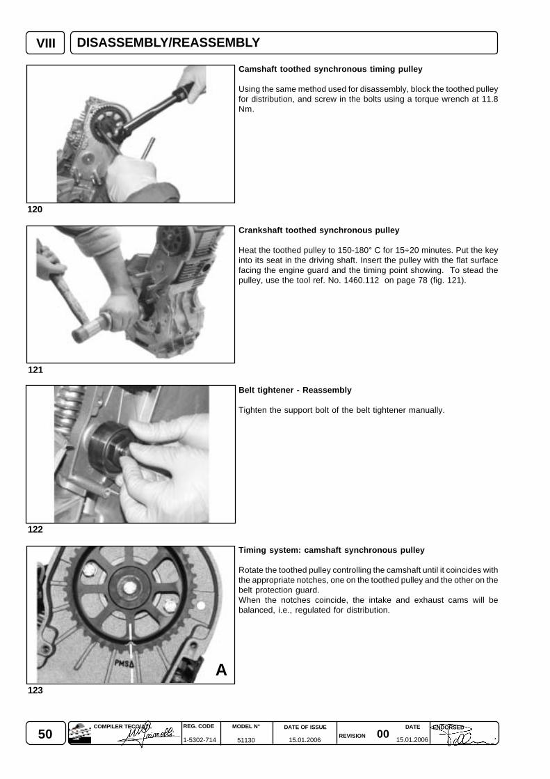
50 0015.01.2006 15.01.2006
REG. CODE
1-5302-714
MODEL N°
51130
DATE OF ISSUE
REVISION
DATE ENDORSEDCOMPILER TECO/ATL
A
VIII
122
121
120
123
Camshaft toothed synchronous timing pulley
Using the same method used for disassembly, block the toothed pulleyfor distribution, and screw in the bolts using a torque wrench at 11.8Nm.
Crankshaft toothed synchronous pulley
Heat the toothed pulley to 150-180° C for 15÷20 minutes. Put the keyinto its seat in the driving shaft. Insert the pulley with the flat surfacefacing the engine guard and the timing point showing. To stead thepulley, use the tool ref. No. 1460.112 on page 78 (fig. 121).
Belt tightener - Reassembly
Tighten the support bolt of the belt tightener manually.
Timing system: camshaft synchronous pulley
Rotate the toothed pulley controlling the camshaft until it coincides withthe appropriate notches, one on the toothed pulley and the other on thebelt protection guard.When the notches coincide, the intake and exhaust cams will bebalanced, i.e., regulated for distribution.
DISASSEMBLY/REASSEMBLY
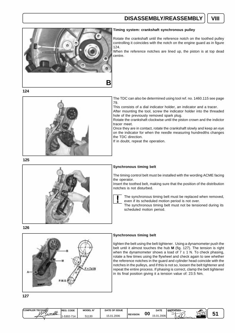
510015.01.2006 15.01.2006
COMPILER TECO/ATL REG. CODE
1-5302-714
MODEL N°
51130
DATE OF ISSUE
REVISION
ENDORSEDDATE
VIII
B
127
126
125
124
Timing system: crankshaft synchronous pulley
Rotate the crankshaft until the reference notch on the toothed pulleycontrolling it coincides with the notch on the engine guard as in figure124.When the reference notches are lined up, the piston is at top deadcentre.
The TDC can also be determined using tool ref. no. 1460.115 see page79.This consists of a dial indicator holder, an indicator and a tracer.After mounting the tool, screw the indicator holder into the threadedhole of the previously removed spark plug.Rotate the crankshaft clockwise until the piston crown and the indictortracer meet.Once they are in contact, rotate the crankshaft slowly and keep an eyeon the indicator for when the needle measuring hundredths changesthe TDC direction.If in doubt, repeat the operation.
Synchronous timing belt
The timing control belt must be installed with the wording ACME facingthe operator.Insert the toothed belt, making sure that the position of the distributionnotches is not disturbed.
The synchronous timing belt must be replaced when removed,even if its scheduled motion period is not over.The synchronous timing belt must not be tensioned during itsscheduled motion period.
Synchronous timing belt
tighten the belt using the belt tightener. Using a dynamometer push thebelt until it almost touches the hub M (fig. 127). The tension is rightwhen the dynamometer shows a load of 7 ± 1 N. To check phasing,rotate a few times using the flywheel and check again to see whetherthe reference notches in the guard and cylinder head coincide with thenotches in the pulleys, and if this is not so, loosen the belt tightener andrepeat the entire process. If phasing is correct, clamp the belt tightenerin its final position giving it a tension value of: 23.5 Nm.
DISASSEMBLY/REASSEMBLY
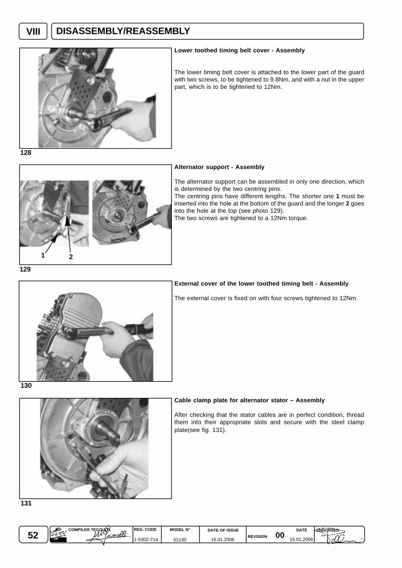
52 0015.01.2006 15.01.2006
REG. CODE
1-5302-714
MODEL N°
51130
DATE OF ISSUE
REVISION
DATE ENDORSEDCOMPILER TECO/ATL
VIII
130
129
128
131
1 2
Lower toothed timing belt cover - Assembly
The lower timing belt cover is attached to the lower part of the guardwith two screws, to be tightened to 9.8Nm, and with a nut in the upperpart, which is to be tightened to 12Nm.
Alternator support - Assembly
The alternator support can be assembled in only one direction, whichis determined by the two centring pins.The centring pins have different lengths. The shorter one 1 must beinserted into the hole at the bottom of the guard and the longer 2 goesinto the hole at the top (see photo 129).The two screws are tightened to a 12Nm torque.
External cover of the lower toothed timing belt - Assembly
The external cover is fixed on with four screws tightened to 12Nm.
Cable clamp plate for alternator stator – Assembly
After checking that the stator cables are in perfect condition, threadthem into their appropriate slots and secure with the steel clampplate(see fig. 131).
DISASSEMBLY/REASSEMBLY
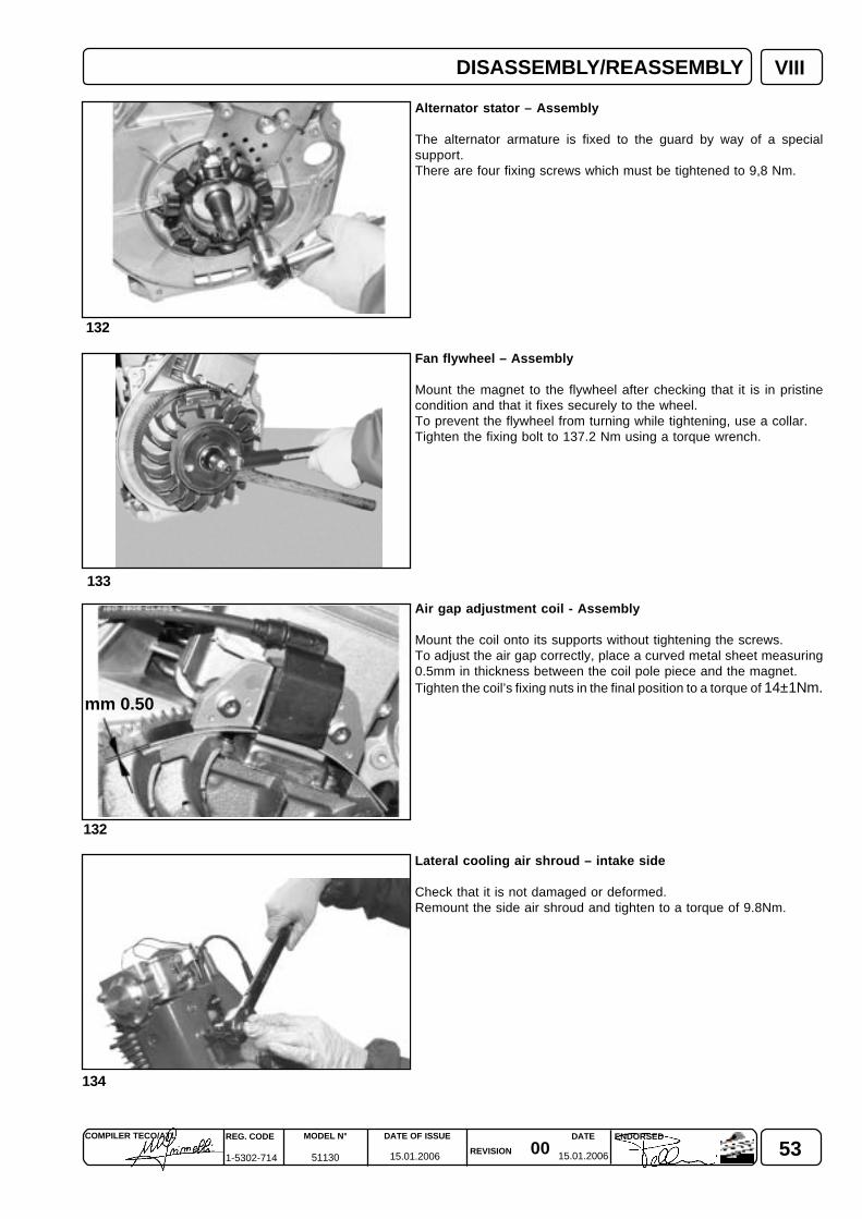
530015.01.2006 15.01.2006
COMPILER TECO/ATL REG. CODE
1-5302-714
MODEL N°
51130
DATE OF ISSUE
REVISION
ENDORSEDDATE
VIII
133
132
134
132
mm 0.50
Alternator stator – Assembly
The alternator armature is fixed to the guard by way of a specialsupport.There are four fixing screws which must be tightened to 9,8 Nm.
Fan flywheel – Assembly
Mount the magnet to the flywheel after checking that it is in pristinecondition and that it fixes securely to the wheel.To prevent the flywheel from turning while tightening, use a collar.Tighten the fixing bolt to 137.2 Nm using a torque wrench.
Air gap adjustment coil - Assembly
Mount the coil onto its supports without tightening the screws.To adjust the air gap correctly, place a curved metal sheet measuring0.5mm in thickness between the coil pole piece and the magnet.Tighten the coil’s fixing nuts in the final position to a torque of 14±1Nm.
Lateral cooling air shroud – intake side
Check that it is not damaged or deformed.Remount the side air shroud and tighten to a torque of 9.8Nm.
DISASSEMBLY/REASSEMBLY
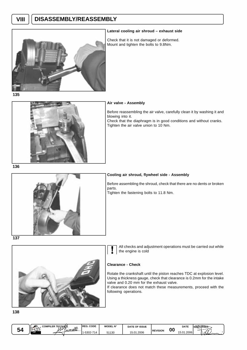
54 0015.01.2006 15.01.2006
REG. CODE
1-5302-714
MODEL N°
51130
DATE OF ISSUE
REVISION
DATE ENDORSEDCOMPILER TECO/ATL
VIII
136
135
137
138
Lateral cooling air shroud – exhaust side
Check that it is not damaged or deformed.Mount and tighten the bolts to 9.8Nm.
Air valve - Assembly
Before reassembling the air valve, carefully clean it by washing it andblowing into it.Check that the diaphragm is in good conditions and without cranks.Tighten the air valve union to 10 Nm.
Cooling air shroud, flywheel side - Assembly
Before assembling the shroud, check that there are no dents or brokenparts.Tighten the fastening bolts to 11.8 Nm.
All checks and adjustment operations must be carried out whilethe engine is cold
Clearance - Check
Rotate the crankshaft until the piston reaches TDC at explosion level.Using a thickness gauge, check that clearance is 0.2mm for the intakevalve and 0.20 mm for the exhaust valve.If clearance does not match these measurements, proceed with thefollowing operations.
DISASSEMBLY/REASSEMBLY
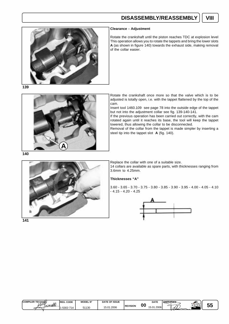
550015.01.2006 15.01.2006
COMPILER TECO/ATL REG. CODE
1-5302-714
MODEL N°
51130
DATE OF ISSUE
REVISION
ENDORSEDDATE
VIII
140
139
141
A
Clearance - Adjustment
Rotate the crankshaft until the piston reaches TDC at explosion levelThis operation allows you to rotate the tappets and bring the lower slotsA (as shown in figure 140) towards the exhaust side, making removalof the collar easier.
Rotate the crankshaft once more so that the valve which is to beadjusted is totally open, i.e. with the tappet flattened by the top of thecam.Insert tool 1460.109 see page 78 into the outside edge of the tappetbut not into the adjustment collar see fig. 139-140-141.If the previous operation has been carried out correctly, with the camrotated again until it reaches its base, the tool will keep the tappetlowered, thus allowing the collar to be disconnected.Removal of the collar from the tappet is made simpler by inserting asteel tip into the tappet slot A (fig. 140).
Replace the collar with one of a suitable size.14 collars are available as spare parts, with thicknesses ranging from3.6mm to 4.25mm.
Thicknesses “A”
3.60 - 3.65 - 3.70 - 3.75 - 3.80 - 3.85 - 3.90 - 3.95 - 4.00 - 4.05 - 4.10- 4.15 - 4.20 - 4.25
DISASSEMBLY/REASSEMBLY

56 0015.01.2006 15.01.2006
REG. CODE
1-5302-714
MODEL N°
51130
DATE OF ISSUE
REVISION
DATE ENDORSEDCOMPILER TECO/ATL
VIII
144
143
142
145
Tappet cover - Assembly
The fixing screws between the cover and the cylinder head must betightened with a torque wrench to 10 Nm.
Spark plug - Assembly
Clean the electrodes with a metal brush (with brass bristles) and blowcompressed air over them.Using a thickness gauge, make sure that the distance betweenelectrodes is 0.70÷0.80 mm.If the ceramic insulation is chipped or if the electrodes are worn away,replace the spark plug with a new one with a suitable thermal value.When replacing, it is advisable to use only recommended spark plugsin order to avoid malfunctioning, which in turn could damage theengine.Recommended spark plugs is:
Brand: CHAMPION Type: CHAMPION RL95YC
Spark plug - Tightening
Mounting and removal of the spark plug must be carried out while theengine is cold.The spark plug should be screwed onto the cylinder head initially byhand, and then tightened to 20Nm with the aid of a torque wrench.
Intake manifold - Assembly
Before assembling the intake manifold, check and replace, if necessary,the gasket placed on the manifold end against the cylinder head.
DISASSEMBLY/REASSEMBLY
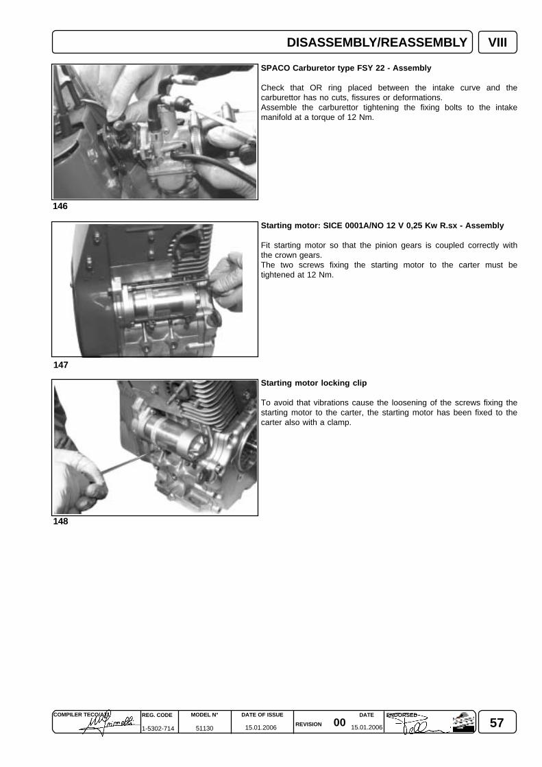
570015.01.2006 15.01.2006
COMPILER TECO/ATL REG. CODE
1-5302-714
MODEL N°
51130
DATE OF ISSUE
REVISION
ENDORSEDDATE
VIII
148
147
146
SPACO Carburetor type FSY 22 - Assembly
Check that OR ring placed between the intake curve and thecarburettor has no cuts, fissures or deformations.Assemble the carburettor tightening the fixing bolts to the intakemanifold at a torque of 12 Nm.
Starting motor: SICE 0001A/NO 12 V 0,25 Kw R.sx - Assembly
Fit starting motor so that the pinion gears is coupled correctly withthe crown gears.The two screws fixing the starting motor to the carter must betightened at 12 Nm.
Starting motor locking clip
To avoid that vibrations cause the loosening of the screws fixing thestarting motor to the carter, the starting motor has been fixed to thecarter also with a clamp.
DISASSEMBLY/REASSEMBLY
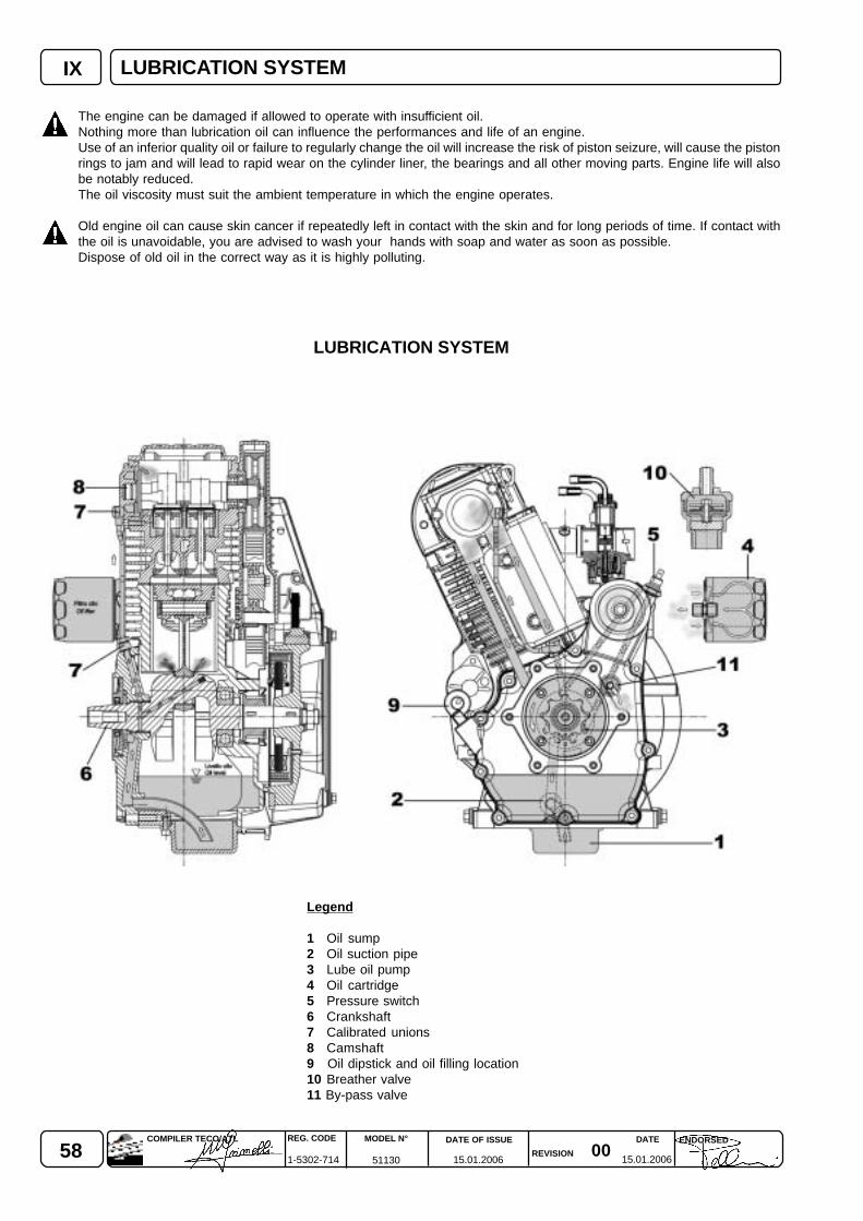
58 0015.01.2006 15.01.2006
REG. CODE
1-5302-714
MODEL N°
51130
DATE OF ISSUE
REVISION
DATE ENDORSEDCOMPILER TECO/ATL
IX LUBRICATION SYSTEM
LUBRICATION SYSTEM
The engine can be damaged if allowed to operate with insufficient oil.Nothing more than lubrication oil can influence the performances and life of an engine.Use of an inferior quality oil or failure to regularly change the oil will increase the risk of piston seizure, will cause the pistonrings to jam and will lead to rapid wear on the cylinder liner, the bearings and all other moving parts. Engine life will alsobe notably reduced.The oil viscosity must suit the ambient temperature in which the engine operates.
Old engine oil can cause skin cancer if repeatedly left in contact with the skin and for long periods of time. If contact withthe oil is unavoidable, you are advised to wash your hands with soap and water as soon as possible.Dispose of old oil in the correct way as it is highly polluting.
Legend
1 Oil sump2 Oil suction pipe3 Lube oil pump4 Oil cartridge5 Pressure switch6 Crankshaft7 Calibrated unions8 Camshaft9 Oil dipstick and oil filling location10 Breather valve11 By-pass valve

590015.01.2006 15.01.2006
COMPILER TECO/ATL REG. CODE
1-5302-714
MODEL N°
51130
DATE OF ISSUE
REVISION
ENDORSEDDATE
XELECTRICAL SYSTEM
Electrical starting system 180 W diagram
Caption
1 Battery2 Voltage regulator3 Alternator4 Starting motor5 Remote control switch6 Key switch7 Ignition coil8 Indicator lamp pressure oil9 Oil pressure gauge10 Alternator Charging Lamp (Off if Charging)11 Filo di connessione impianto a gas
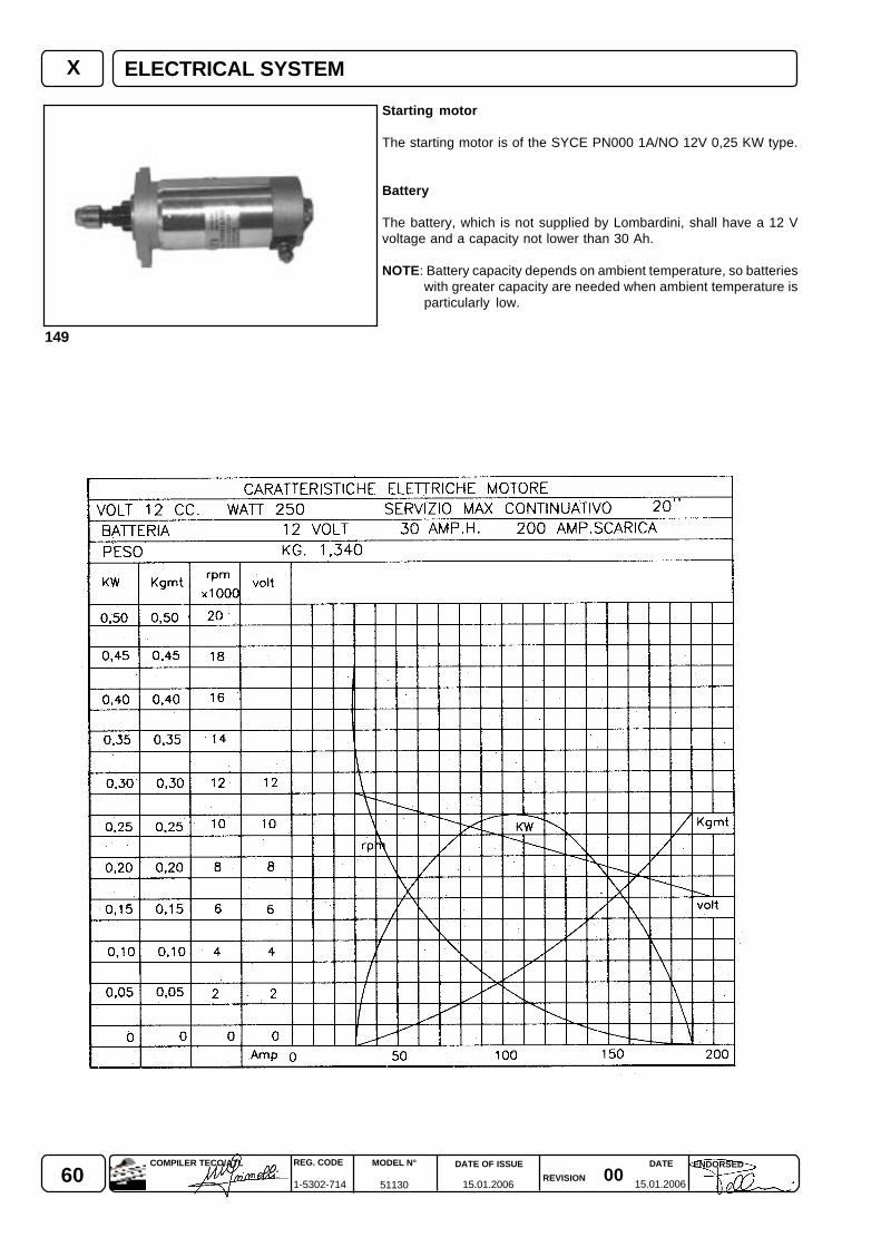
60 0015.01.2006 15.01.2006
REG. CODE
1-5302-714
MODEL N°
51130
DATE OF ISSUE
REVISION
DATE ENDORSEDCOMPILER TECO/ATL
X
149
ELECTRICAL SYSTEM
Starting motor
The starting motor is of the SYCE PN000 1A/NO 12V 0,25 KW type.
Battery
The battery, which is not supplied by Lombardini, shall have a 12 Vvoltage and a capacity not lower than 30 Ah.
NOTE: Battery capacity depends on ambient temperature, so batterieswith greater capacity are needed when ambient temperature isparticularly low.
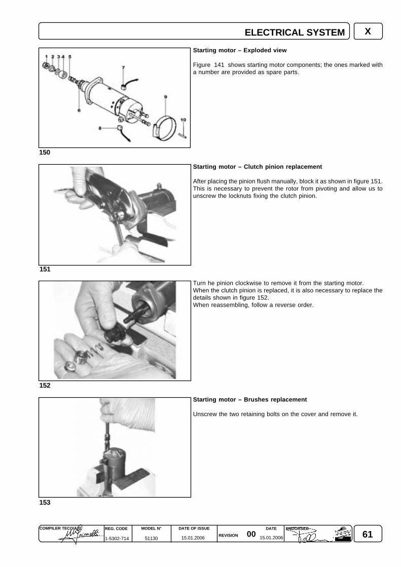
610015.01.2006 15.01.2006
COMPILER TECO/ATL REG. CODE
1-5302-714
MODEL N°
51130
DATE OF ISSUE
REVISION
ENDORSEDDATE
X
150
152
151
153
Starting motor – Exploded view
Figure 141 shows starting motor components; the ones marked witha number are provided as spare parts.
Starting motor – Clutch pinion replacement
After placing the pinion flush manually, block it as shown in figure 151.This is necessary to prevent the rotor from pivoting and allow us tounscrew the locknuts fixing the clutch pinion.
Turn he pinion clockwise to remove it from the starting motor.When the clutch pinion is replaced, it is also necessary to replace thedetails shown in figure 152.When reassembling, follow a reverse order.
Starting motor – Brushes replacement
Unscrew the two retaining bolts on the cover and remove it.
ELECTRICAL SYSTEM
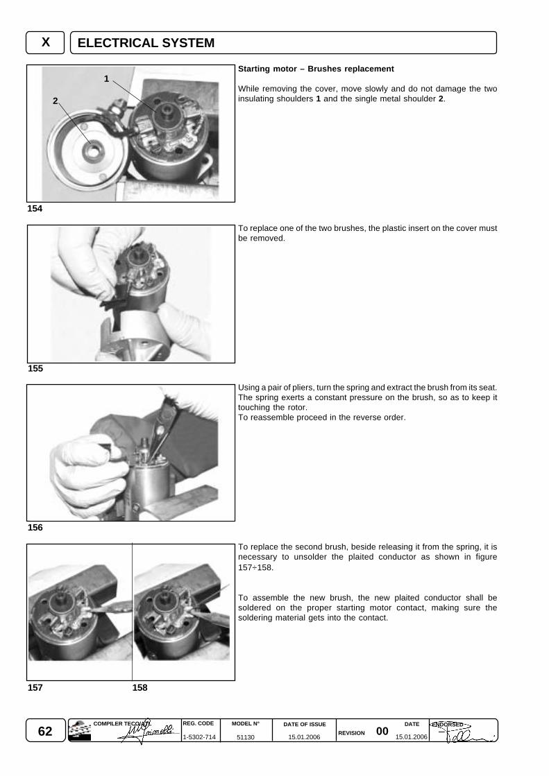
62 0015.01.2006 15.01.2006
REG. CODE
1-5302-714
MODEL N°
51130
DATE OF ISSUE
REVISION
DATE ENDORSEDCOMPILER TECO/ATL
156
155
154
157 158
1
2
X
Starting motor – Brushes replacement
While removing the cover, move slowly and do not damage the twoinsulating shoulders 1 and the single metal shoulder 2.
To replace one of the two brushes, the plastic insert on the cover mustbe removed.
Using a pair of pliers, turn the spring and extract the brush from its seat.The spring exerts a constant pressure on the brush, so as to keep ittouching the rotor.To reassemble proceed in the reverse order.
To replace the second brush, beside releasing it from the spring, it isnecessary to unsolder the plaited conductor as shown in figure157÷158.
To assemble the new brush, the new plaited conductor shall besoldered on the proper starting motor contact, making sure thesoldering material gets into the contact.
ELECTRICAL SYSTEM
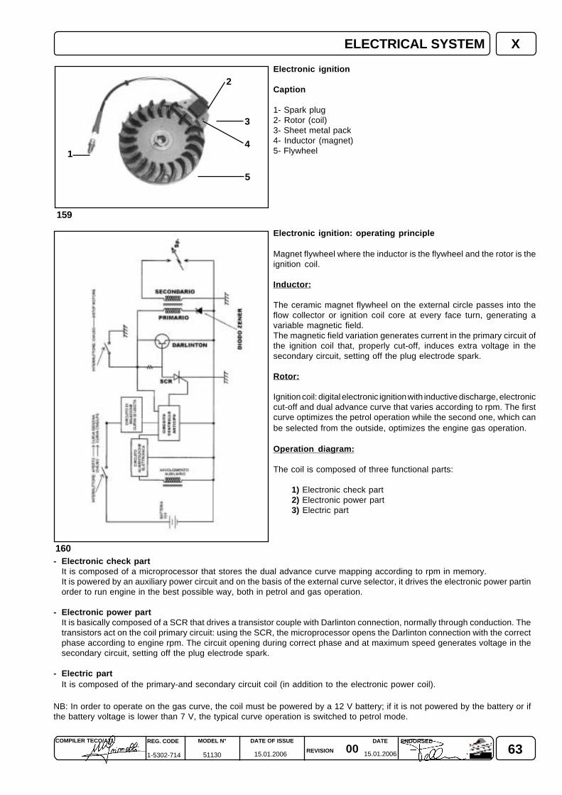
630015.01.2006 15.01.2006
COMPILER TECO/ATL REG. CODE
1-5302-714
MODEL N°
51130
DATE OF ISSUE
REVISION
ENDORSEDDATE
159
160
4
3
5
1
2
X
Electronic ignition
Caption
1- Spark plug2- Rotor (coil)3- Sheet metal pack4- Inductor (magnet)5- Flywheel
Electronic ignition: operating principle
Magnet flywheel where the inductor is the flywheel and the rotor is theignition coil.
Inductor:
The ceramic magnet flywheel on the external circle passes into theflow collector or ignition coil core at every face turn, generating avariable magnetic field.The magnetic field variation generates current in the primary circuit ofthe ignition coil that, properly cut-off, induces extra voltage in thesecondary circuit, setting off the plug electrode spark.
Rotor:
Ignition coil: digital electronic ignition with inductive discharge, electroniccut-off and dual advance curve that varies according to rpm. The firstcurve optimizes the petrol operation while the second one, which canbe selected from the outside, optimizes the engine gas operation.
Operation diagram:
The coil is composed of three functional parts:
1) Electronic check part2) Electronic power part3) Electric part
- Electronic check partIt is composed of a microprocessor that stores the dual advance curve mapping according to rpm in memory.It is powered by an auxiliary power circuit and on the basis of the external curve selector, it drives the electronic power partinorder to run engine in the best possible way, both in petrol and gas operation.
- Electronic power partIt is basically composed of a SCR that drives a transistor couple with Darlinton connection, normally through conduction. Thetransistors act on the coil primary circuit: using the SCR, the microprocessor opens the Darlinton connection with the correctphase according to engine rpm. The circuit opening during correct phase and at maximum speed generates voltage in thesecondary circuit, setting off the plug electrode spark.
- Electric partIt is composed of the primary-and secondary circuit coil (in addition to the electronic power coil).
NB: In order to operate on the gas curve, the coil must be powered by a 12 V battery; if it is not powered by the battery or ifthe battery voltage is lower than 7 V, the typical curve operation is switched to petrol mode.
ELECTRICAL SYSTEM
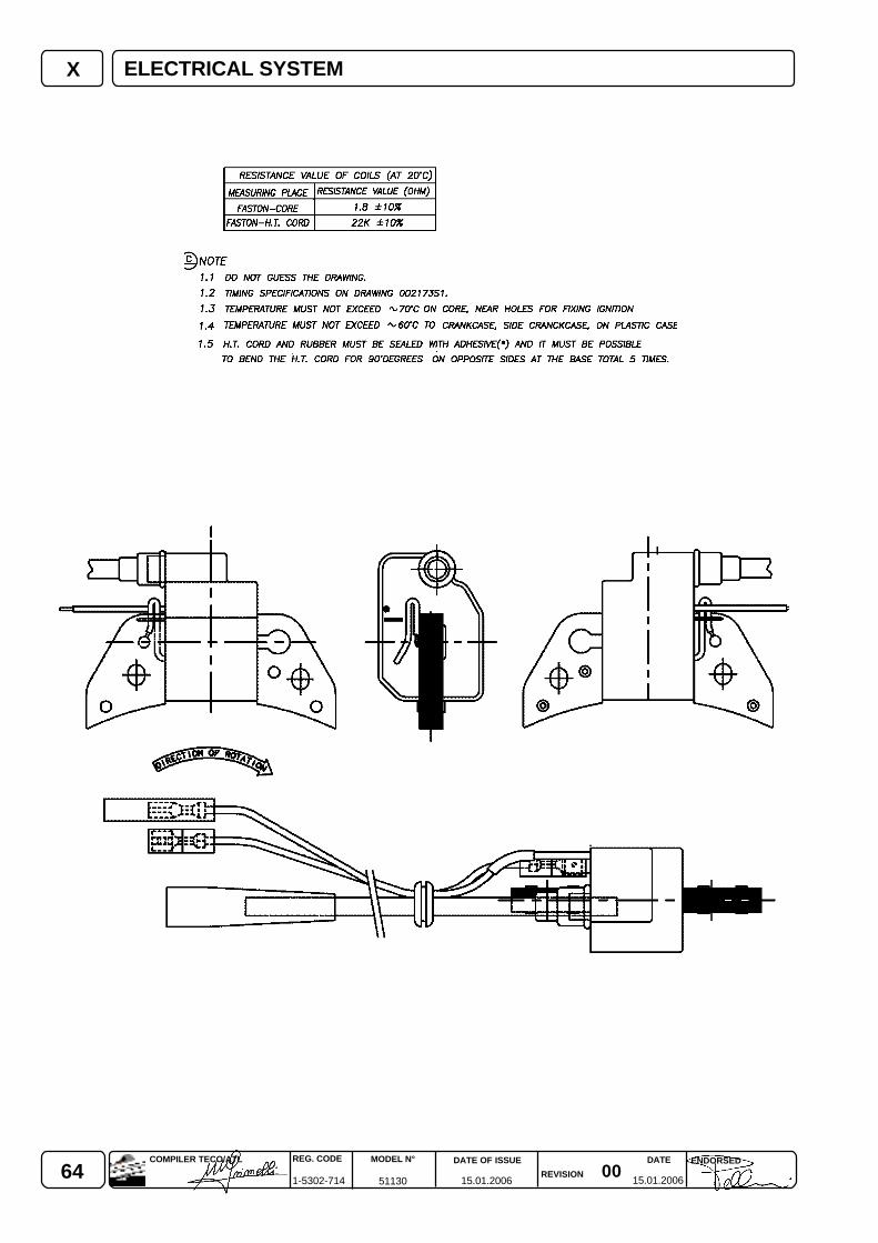
64 0015.01.2006 15.01.2006
REG. CODE
1-5302-714
MODEL N°
51130
DATE OF ISSUE
REVISION
DATE ENDORSEDCOMPILER TECO/ATL
X ELECTRICAL SYSTEM
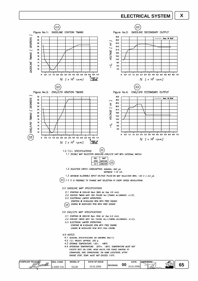
650015.01.2006 15.01.2006
COMPILER TECO/ATL REG. CODE
1-5302-714
MODEL N°
51130
DATE OF ISSUE
REVISION
ENDORSEDDATE
XELECTRICAL SYSTEM
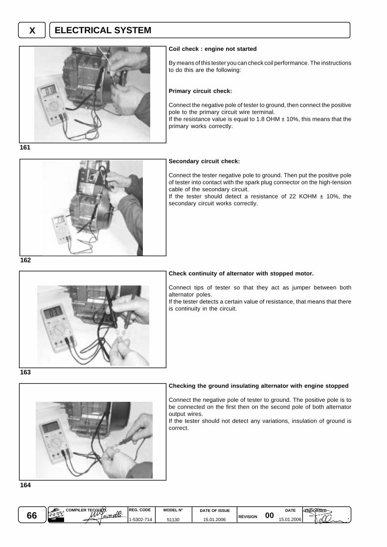
66 0015.01.2006 15.01.2006
REG. CODE
1-5302-714
MODEL N°
51130
DATE OF ISSUE
REVISION
DATE ENDORSEDCOMPILER TECO/ATL
X
163
162
161
164
ELECTRICAL SYSTEM
Coil check : engine not started
By means of this tester you can check coil performance. The instructionsto do this are the following:
Primary circuit check:
Connect the negative pole of tester to ground, then connect the positivepole to the primary circuit wire terminal.If the resistance value is equal to 1.8 OHM ± 10%, this means that theprimary works correctly.
Secondary circuit check:
Connect the tester negative pole to ground. Then put the positive poleof tester into contact with the spark plug connector on the high-tensioncable of the secondary circuit.If the tester should detect a resistance of 22 KOHM ± 10%, thesecondary circuit works correctly.
Check continuity of alternator with stopped motor.
Connect tips of tester so that they act as jumper between bothalternator poles.If the tester detects a certain value of resistance, that means that thereis continuity in the circuit.
Checking the ground insulating alternator with engine stopped
Connect the negative pole of tester to ground. The positive pole is tobe connected on the first then on the second pole of both alternatoroutput wires.If the tester should not detect any variations, insulation of ground iscorrect.
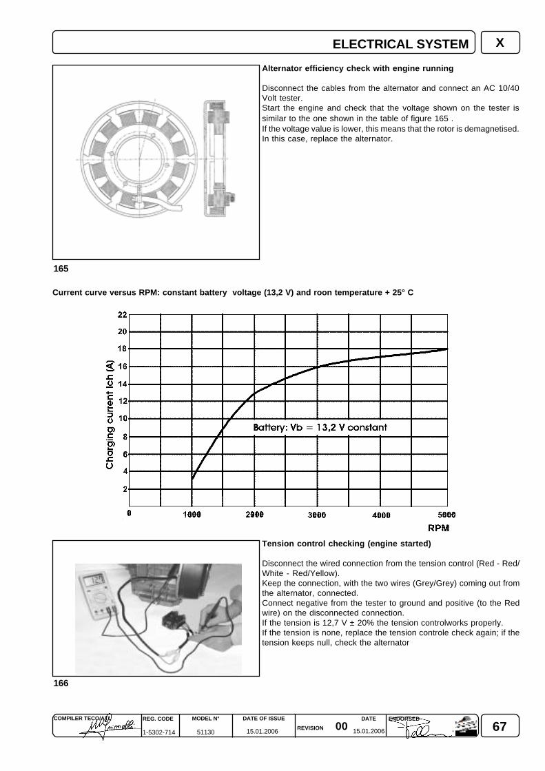
670015.01.2006 15.01.2006
COMPILER TECO/ATL REG. CODE
1-5302-714
MODEL N°
51130
DATE OF ISSUE
REVISION
ENDORSEDDATE
165
166
X
Alternator efficiency check with engine running
Disconnect the cables from the alternator and connect an AC 10/40Volt tester.Start the engine and check that the voltage shown on the tester issimilar to the one shown in the table of figure 165 .If the voltage value is lower, this means that the rotor is demagnetised.In this case, replace the alternator.
Tension control checking (engine started)
Disconnect the wired connection from the tension control (Red - Red/White - Red/Yellow).Keep the connection, with the two wires (Grey/Grey) coming out fromthe alternator, connected.Connect negative from the tester to ground and positive (to the Redwire) on the disconnected connection.If the tension is 12,7 V ± 20% the tension controlworks properly.If the tension is none, replace the tension controle check again; if thetension keeps null, check the alternator
Current curve versus RPM: constant battery voltage (13,2 V) and roon temperature + 25° C
ELECTRICAL SYSTEM
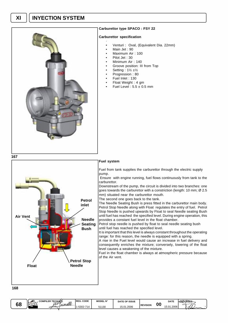
68 0015.01.2006 15.01.2006
REG. CODE
1-5302-714
MODEL N°
51130
DATE OF ISSUE
REVISION
DATE ENDORSEDCOMPILER TECO/ATL
XI
168
167
INYECTION SYSTEM
Float
Air Vent
Petrolinlet
NeedleSeatingBush
Petrol StopNeedle
Carburettor type SPACO : FSY 22
Carburettor specification·• Venturi : Oval, (Equivalent Dia. 22mm)• Main Jet : 90• Maximum Air : 100• Pilot Jet : 30• Minimum Air : 140• Groove position: III from Top• Setting : 1½ ±½• Progression : 80• Fuel Inlet : 130• Float Weight : 4 gm• Fuel Level : 5.5 ± 0.5 mm
Fuel system
Fuel from tank supplies the carburettor through the electric supplypump. Ensure with engine running, fuel flows continuously from tank to thecarburettor.Downstream of the pump, the circuit is divided into two branches: onegoes towards the carburettor with a constriction (length: 10 mm; Ø 2.5mm) situated near the carburettor mouth.The second one goes back to the tank.The Needle Seating Bush is press fitted in the carburettor main body.Petrol Stop Needle along with Float regulates the entry of fuel. PetrolStop Needle is pushed upwards by Float to seal Needle seating Bushuntil fuel has reached the specified level. During engine operation, thisprovides a constant fuel level in the float chamber.Petrol stop needle is pushed by float to seal needle seating bushuntil fuel has reached the specified level.It is important that this level is always constant throughout the operatingrange: for this reason, the needle is equipped with a spring.A rise in the Fuel level would cause an increase in fuel delivery andconsequently enriches the mixture; conversely, lowering of the floatlevel causes a weakening of the mixture.Fuel in the float chamber is always at atmospheric pressure becauseof the Air vent.
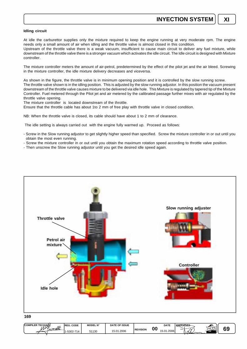
690015.01.2006 15.01.2006
COMPILER TECO/ATL REG. CODE
1-5302-714
MODEL N°
51130
DATE OF ISSUE
REVISION
ENDORSEDDATE
169
XIINYECTION SYSTEM
Petrol airmixture
Throttle valve
Idle hole
Slow running adjuster
Controller
Idling circuit
At idle the carburettor supplies only the mixture required to keep the engine running at very moderate rpm. The engineneeds only a small amount of air when idling and the throttle valve is almost closed in this condition.Upstream of the throttle valve there is a weak vacuum, insufficient to cause main circuit to deliver any fuel mixture, whiledownstream of the throttle valve there is a stronger vacuum which activates the idle circuit. The Idle circuit is designed with Mixturecontroller.
The mixture controller meters the amount of air-petrol, predetermined by the effect of the pilot jet and the air bleed. Screwingin the mixture controller, the idle mixture delivery decreases and viceversa.
As shown in the figure, the throttle valve is in minimum opening position and it is controlled by the slow running screw.The throttle valve shown is in the idling position. This is adjusted by the slow running adjustor. In this position the vacuum presentdownstream of the throttle valve causes mixture to be delivered via idle hole. This Mixture is regulated by tapered tip of the MixtureController. Fuel metered through the Pilot jet and air metered by the calibrated passage further mixes with air regulated by thethrottle valve opening.The mixture controller is located downstream of the throttle.Ensure that the throttle cable has about 1to 2 mm of free play with throttle valve in closed condition.
NB: When the throttle valve is closed, its cable should have about 1 to 2 mm of clearance.
The idle setting is always carried out with the engine fully warmed up. Proceed as follows:
- Screw in the Slow running adjustor to get slightly higher speed than specified. Screw the mixture controller in or out until youobtain the most even running.
- Screw the mixture controller in or out until you obtain the maximum rotation speed according to throttle valve position.- Then unscrew the Slow running adjustor until you get the desired idle speed again.
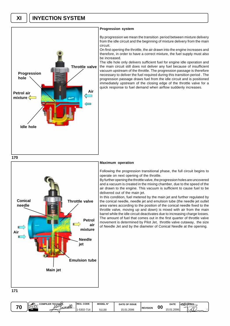
70 0015.01.2006 15.01.2006
REG. CODE
1-5302-714
MODEL N°
51130
DATE OF ISSUE
REVISION
DATE ENDORSEDCOMPILER TECO/ATL
XI
171
170
INYECTION SYSTEM
Progression system
By progression we mean the transition period between mixture deliveryfrom the idle circuit and the beginning of mixture delivery from the maincircuit.On first opening the throttle, the air drawn into the engine increases andtherefore, in order to have a correct mixture, the fuel supply must alsobe increased.The idle hole only delivers sufficient fuel for engine idle operation andthe main circuit still does not deliver any fuel because of insufficientvacuum upstream of the throttle. The progression passage is thereforenecessary to deliver the fuel required during this transition period . Theprogression passage draws fuel from the idle circuit and is positionedimmediately upstream of the closing edge of the throttle valve for aquick response to fuel demand when airflow suddenly increases.
Maximum operation
Following the progression transitional phase, the full circuit begins tooperate on next opening of the throttle.By further opening the throttle valve, the progression holes are uncoveredand a vacuum is created in the mixing chamber, due to the speed of theair drawn to the engine. This vacuum is sufficient to cause fuel to bedelivered out of the main jet.In this condition, fuel metered by the main jet and further regulated bythe conical needle, needle jet and emulsion tube (the needle jet outletarea varies according to the position of the conical needle fixed to thethrottle valve, moving up and down) is mixed with air from the mainbarrel while the idle circuit deactivates due to increasing charge losses.The amount of fuel that comes out in the first quarter of throttle valvemovement is determined by Pilot Jet, throttle valve cutaway, the sizeof Needle Jet and by the diameter of Conical Needle at the opening.
Air
Throttle valve
Progressionhole
Idle hole
Petrol airmixture
Air
Main jet
Emulsion tube
Needlejet
Petrolair
mixture
Throttle valveConicalneedle
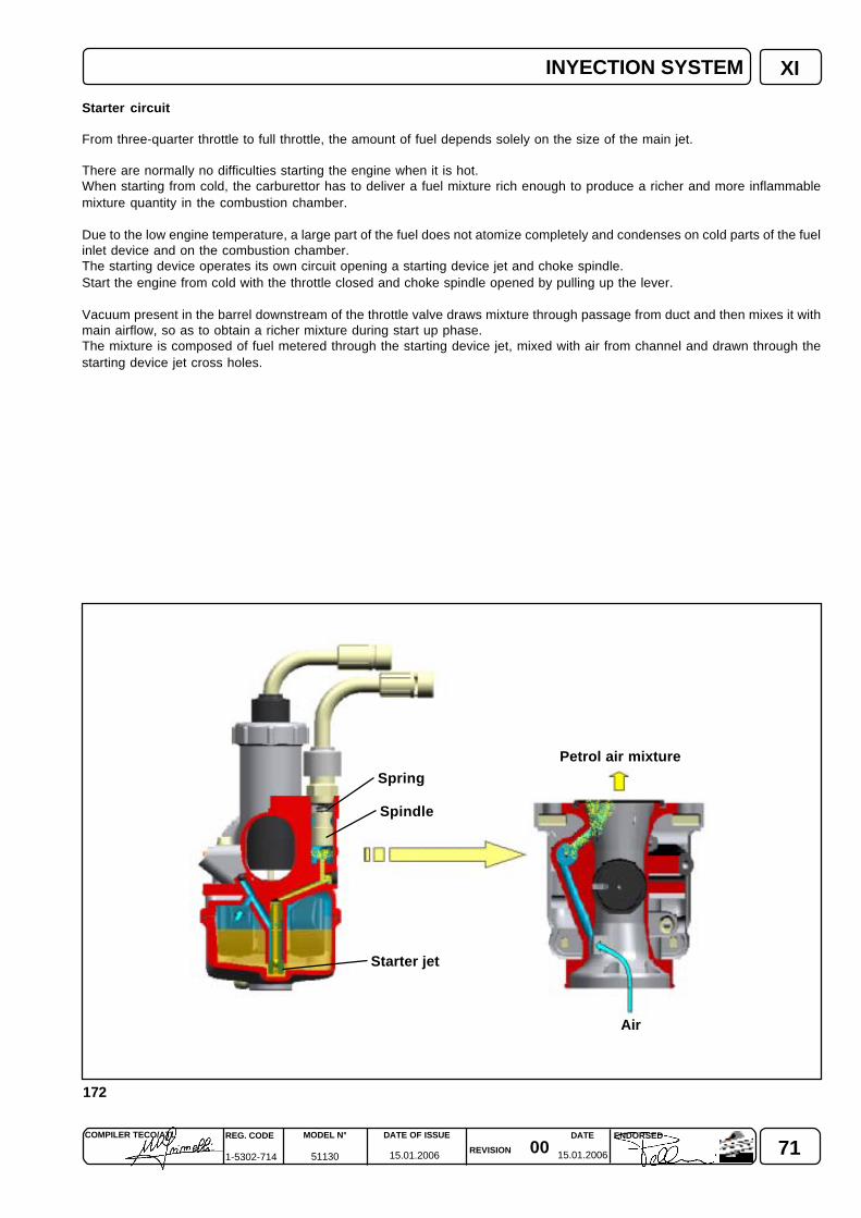
710015.01.2006 15.01.2006
COMPILER TECO/ATL REG. CODE
1-5302-714
MODEL N°
51130
DATE OF ISSUE
REVISION
ENDORSEDDATE
172
XI
Spindle
Spring
Starter jet
Petrol air mixture
Air
Starter circuit
From three-quarter throttle to full throttle, the amount of fuel depends solely on the size of the main jet.
There are normally no difficulties starting the engine when it is hot.When starting from cold, the carburettor has to deliver a fuel mixture rich enough to produce a richer and more inflammablemixture quantity in the combustion chamber.
Due to the low engine temperature, a large part of the fuel does not atomize completely and condenses on cold parts of the fuelinlet device and on the combustion chamber.The starting device operates its own circuit opening a starting device jet and choke spindle.Start the engine from cold with the throttle closed and choke spindle opened by pulling up the lever.
Vacuum present in the barrel downstream of the throttle valve draws mixture through passage from duct and then mixes it withmain airflow, so as to obtain a richer mixture during start up phase.The mixture is composed of fuel metered through the starting device jet, mixed with air from channel and drawn through thestarting device jet cross holes.
INYECTION SYSTEM
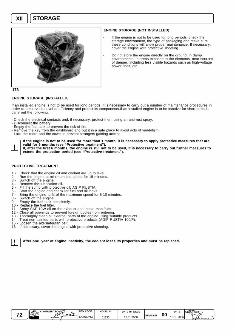
72 0015.01.2006 15.01.2006
REG. CODE
1-5302-714
MODEL N°
51130
DATE OF ISSUE
REVISION
DATE ENDORSEDCOMPILER TECO/ATL
XII
173
ENGINE STORAGE (NOT INSTALLED)
- If the engine is not to be used for long periods, check thestorage environment, the type of packaging and make surethese conditions will allow proper maintenance. If necessary,cover the engine with protective sheeting.
- Do not store the engine directly on the ground, in dampenvironments, in areas exposed to the elements, near sourcesof danger, including less visible hazards such as high-voltagepower lines, etc.
ENGINE STORAGE (INSTALLED)
If an installed engine is not to be used for long periods, it is necessary to carry out a number of maintenance procedures inorder to preserve its level of efficiency and protect its components.If an installed engine is to be inactive for short periods,carry out the following:
- Check the electrical contacts and, if necessary, protect them using an anti-rust spray.- Disconnect the battery.- Empty the fuel tank to prevent the risk of fire.- Remove the key from the dashboard and put it in a safe place to avoid acts of vandalism.- Lock the cabin and the cowls to prevent strangers gaining access.
If the engine is not to be used for more than 1 month, it is necessary to apply protective measures that arevalid for 6 months (see “Protective treatment”).If, after the first 6 months, the engine is still not to be used, it is necessary to carry out further measures toextend the protection period (see “Protective treatment”).
PROTECTIVE TREATMENT
1 - Check that the engine oil and coolant are up to level.2 - Run the engine at minimum idle speed for 15 minutes.3 - Switch off the engine.4 - Remove the lubrication oil.5 - Fill the sump with protective oil: AGIP RUSTIA.6 - Start the engine and check for fuel and oil leaks.7 - Bring the engine to ¾ of the maximum speed for 5-10 minutes.8 - Switch off the engine.9 - Empty the fuel tank completely.10 - Replace the fuel filter.11 - Spray SAE 10W oil on the exhaust and intake manifolds.12 - Close all openings to prevent foreign bodies from entering.13 - Thoroughly clean all external parts of the engine using suitable products.14 - Treat non-painted parts with protective products (AGIP RUSTIA 100/F).15 - Loosen the alternator/fan belt.16 - If necessary, cover the engine with protective sheeting.
After one year of engine inactivity, the coolant loses its properties and must be replaced.
STORAGE
730015.01.2006 15.01.2006
COMPILER TECO/ATL REG. CODE
1-5302-714
MODEL N°
51130
DATE OF ISSUE
REVISION
ENDORSEDDATE
XII
PREPARING THE ENGINE FOR OPERATION AFTER PROTECTIVE TREATMENT
After a period of inactivity and before installing and running the engine, it is necessary to carry out a few measures in orderto ensure that it runs at maximum efficiency.
1 - Remove the protective sheeting.2 - Eliminate any blockages in the exhaust and intake ducts.3 - Use a cloth soaked in degreasing product to remove the external protective treatment.4 - Remove the intake manifold.5 - Inject lubrication oil (no more than 2 cm3) into the valves and install the intake manifold.6 - Adjust the alternator/fan belt tension7 - Turn the flywheel manually to check the movement of the mechanical parts.8 - Refill the tank with fresh fuel.9 - Start the engine and run at ¾ of the maximum speed for 5-10 minutes.10 - Switch off the engine.11 - Remove the protective oil to replace with engine oil.12 - Introduce new oil (see “Lubricants”) up to the correct level marked on the dipstick.13 - Replace the filters (air, oil, fuel) with original spare parts.14 - Empty the cooling circuit completely and pour in the new coolant up to the correct level.
Over time, a number of engine components and lubricants lose their properties, even when the engine is notin use, and so it is important to consider whether they need replacing, based not only on the mileage, butalso on age and wear.
15 - Install the engine and make the necessary connections and unions.16 - Make sure that electrical contacts are intact and efficient.17 - Check that the engine oil and coolant are up to level.18 - Start the engine and keep at minimum speed for a few minutes.19 - Check for leaks and, if necessary, find and eliminate the cause.20 - Switch off the engine.21 - Double check that the engine oil and coolant are up to level.
IF STORAGE EXCEEDS 6 MONTHS PLEASE CONTACT LOMBARDINI AUTHORIZED SERVICE CENTRES.
STORAGE
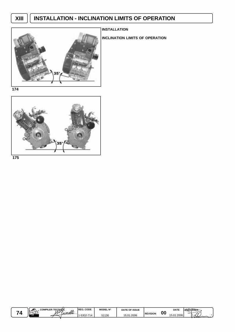
74 0015.01.2006 15.01.2006
REG. CODE
1-5302-714
MODEL N°
51130
DATE OF ISSUE
REVISION
DATE ENDORSEDCOMPILER TECO/ATL
174
175
XIII
INSTALLATION
INCLINATION LIMITS OF OPERATION
INSTALLATION - INCLINATION LIMITS OF OPERATION
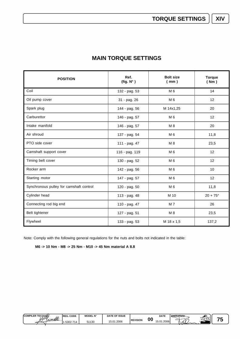
750015.01.2006 15.01.2006
COMPILER TECO/ATL REG. CODE
1-5302-714
MODEL N°
51130
DATE OF ISSUE
REVISION
ENDORSEDDATE
14
12
20
12
20
11,8
23,5
12
12
10
12
11,8
20 + 75°
26
23,5
137,2
M 6
M 6
M 14x1,25
M 6
M 8
M 6
M 8
M 6
M 6
M 6
M 6
M 6
M 10
M 7
M 8
M 18 x 1,5
132 - pag. 53
31 - pag. 26
144 - pag. 56
146 - pag. 57
146 - pag. 57
137 - pag. 54
111 - pag. 47
116 - pag. 119
130 - pag. 52
142 - pag. 56
147 - pag. 57
120 - pag. 50
113 - pag. 48
110 - pag. 47
127 - pag. 51
133 - pag. 53
XIVTORQUE SETTINGS
POSITION Torque( Nm )
Bolt size( mm )
Ref.(fig. N° )
Coil
Oil pump cover
Spark plug
Carburettor
Intake manifold
Air shroud
PTO side cover
Camshaft support cover
Timing belt cover
Rocker arm
Starting motor
Synchronous pulley for camshaft control
Cylinder head
Connecting rod big end
Belt tightener
Flywheel
MAIN TORQUE SETTINGS
Note: Comply with the following general regulations for the nuts and bolts not indicated in the table:
M6 -> 10 Nm - M8 -> 25 Nm - M10 -> 45 Nm material A 8.8
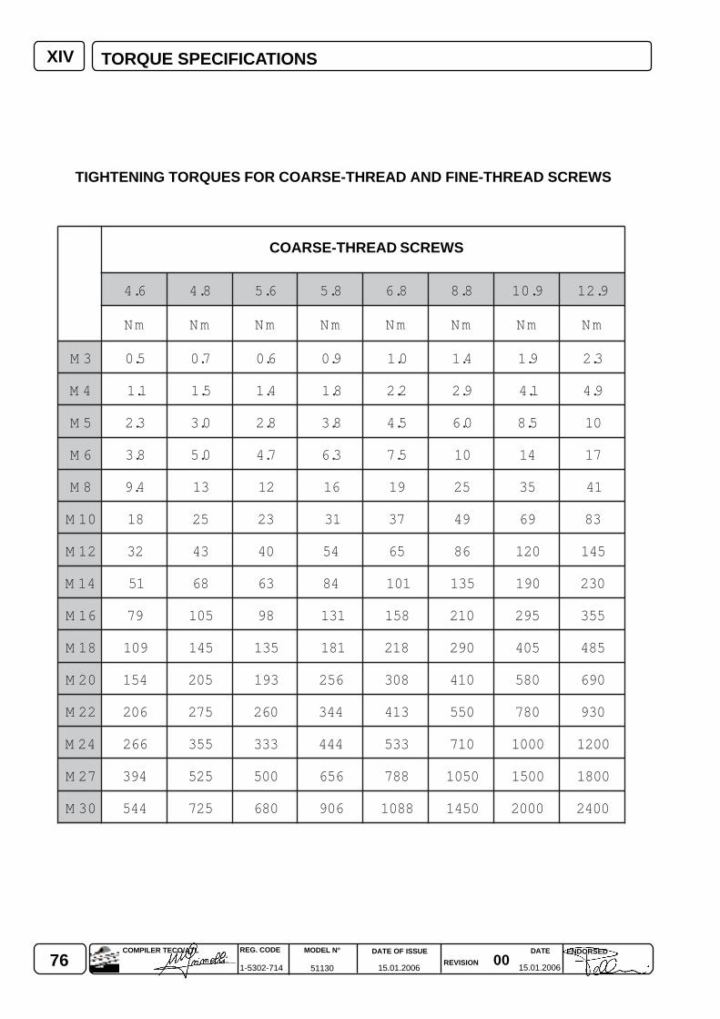
76 0015.01.2006 15.01.2006
REG. CODE
1-5302-714
MODEL N°
51130
DATE OF ISSUE
REVISION
DATE ENDORSEDCOMPILER TECO/ATL
XIV
6.4 8.4 6.5 8.5 8.6 8.8 9.01 9.21
mN mN mN mN mN mN mN mN
3M 5.0 7.0 6.0 9.0 0.1 4.1 9.1 3.2
4M 1.1 5.1 4.1 8.1 2.2 9.2 1.4 9.4
5M 3.2 0.3 8.2 8.3 5.4 0.6 5.8 01
6M 8.3 0.5 7.4 3.6 5.7 01 41 71
8M 4.9 31 21 61 91 52 53 14
01M 81 52 32 13 73 94 96 38
21M 23 34 04 45 56 68 021 541
41M 15 86 36 48 101 531 091 032
61M 97 501 89 131 851 012 592 553
81M 901 541 531 181 812 092 504 584
02M 451 502 391 652 803 014 085 096
22M 602 572 062 443 314 055 087 039
42M 662 553 333 444 335 017 0001 0021
72M 493 525 005 656 887 0501 0051 0081
03M 445 527 086 609 8801 0541 0002 0042
TORQUE SPECIFICATIONS
COARSE-THREAD SCREWS
TIGHTENING TORQUES FOR COARSE-THREAD AND FINE-THREAD SCREWS
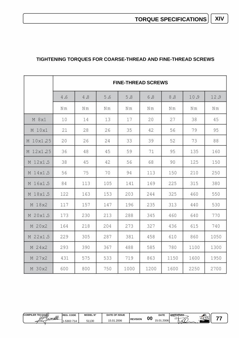
770015.01.2006 15.01.2006
COMPILER TECO/ATL REG. CODE
1-5302-714
MODEL N°
51130
DATE OF ISSUE
REVISION
ENDORSEDDATE
XIV
6.4 8.4 6.5 8.5 8.6 8.8 9.01 9.21
mN mN mN mN mN mN mN mN
1x8M 01 41 31 71 02 72 83 54
1x01M 12 82 62 53 24 65 97 59
52.1x01M 02 62 42 33 93 25 37 88
52.1x21M 63 84 54 95 17 59 531 061
5.1x21M 83 54 24 65 86 09 521 051
5.1x41M 65 57 07 49 311 051 012 052
5.1x61M 48 311 501 141 961 522 513 083
5.1x81M 221 361 351 302 442 523 064 055
2x81M 711 751 741 691 532 313 044 035
5.1x02M 371 032 312 882 543 064 046 077
2x02M 461 812 402 372 723 634 516 047
5.1x22M 922 503 782 183 854 016 068 0501
2x42M 392 093 763 884 585 087 0011 0031
2x72M 134 575 335 917 368 0511 0061 0591
2x03M 006 008 057 0001 0021 0061 0522 0072
TORQUE SPECIFICATIONS
FINE-THREAD SCREWS
TIGHTENING TORQUES FOR COARSE-THREAD AND FINE-THREAD SCREWS
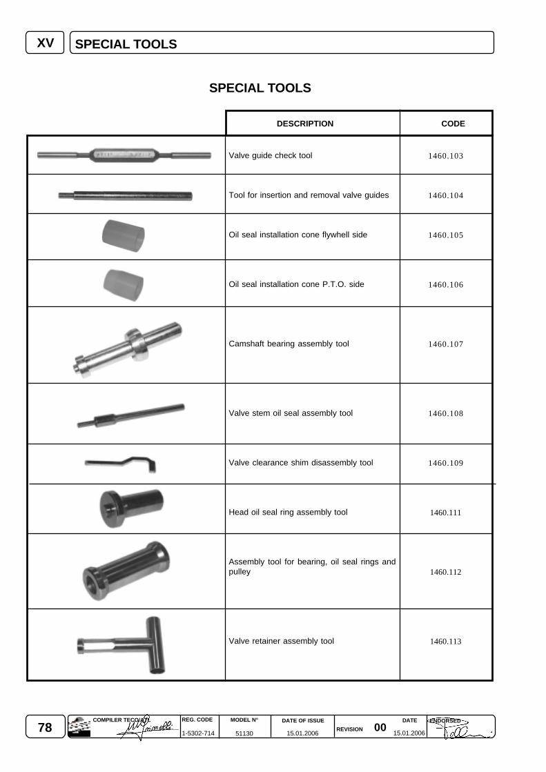
78 0015.01.2006 15.01.2006
REG. CODE
1-5302-714
MODEL N°
51130
DATE OF ISSUE
REVISION
DATE ENDORSEDCOMPILER TECO/ATL
XV
1460.103
1460.104
1460.105
1460.106
1460.107
1460.108
1460.109
1460.111
1460.112
1460.113
SPECIAL TOOLS
CODEDESCRIPTION
Valve guide check tool
Tool for insertion and removal valve guides
Oil seal installation cone flywhell side
Oil seal installation cone P.T.O. side
Camshaft bearing assembly tool
Valve stem oil seal assembly tool
Valve clearance shim disassembly tool
Head oil seal ring assembly tool
Assembly tool for bearing, oil seal rings andpulley
Valve retainer assembly tool
SPECIAL TOOLS
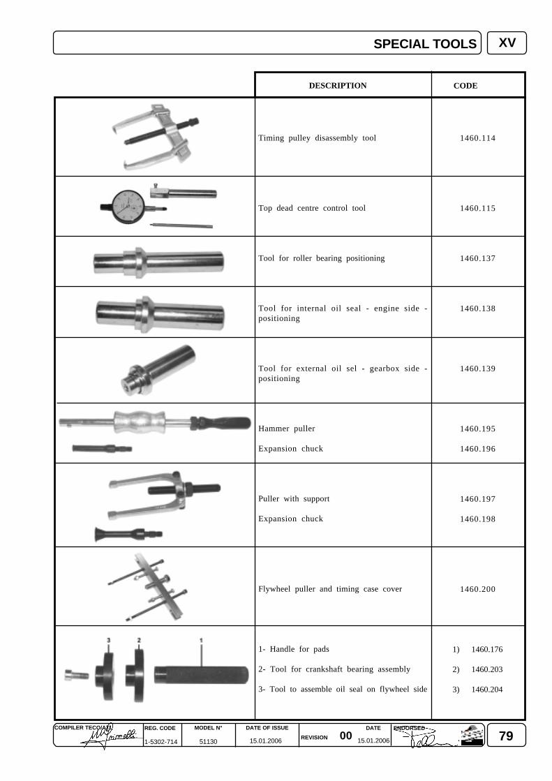
790015.01.2006 15.01.2006
COMPILER TECO/ATL REG. CODE
1-5302-714
MODEL N°
51130
DATE OF ISSUE
REVISION
ENDORSEDDATE
1460.114
1460.115
1460.137
1460.138
1460.139
1460.195
1460.196
1460.197
1460.198
1460.200
1) 1460.176
2) 1460.203
3) 1460.204
XV
Timing pulley disassembly tool
Top dead centre control tool
Tool for roller bearing positioning
Tool for internal oil seal - engine side -positioning
Tool for external oil sel - gearbox side -positioning
Hammer puller
Expansion chuck
Puller with support
Expansion chuck
Flywheel puller and timing case cover
1- Handle for pads
2- Tool for crankshaft bearing assembly
3- Tool to assemble oil seal on flywheel side
CODE DESCRIPTION
SPECIAL TOOLS
80 0015.01.2006 15.01.2006
REG. CODE
1-5302-714
MODEL N°
51130
DATE OF ISSUE
REVISION
DATE ENDORSEDCOMPILER TECO/ATL
NOTES

810015.01.2006 15.01.2006
COMPILER TECO/ATL REG. CODE
1-5302-714
MODEL N°
51130
DATE OF ISSUE
REVISION
ENDORSEDDATE
NOTES
La Lombardini si riserva il diritto di modificare in qualunque momento i dati contenuti in questa pubblicazione.Lombardini se rèserve le droit de modifier, à n'importe quel moment, les données reportées dans cettepublication.Data reported in this issue can be modified at any time by Lombardini.Lombardini vorbehält alle Rechte, diese Angabe jederzeit verändern.La Lombardini se reserva el derecho de modificar sin previo aviso los datos de esta publicación.
82
42100 Reggio Emilia – Italia - ITALYVia Cav. del Lavoro Adelmo Lombardini, 2 - Cas. Post. 1074Tel. (+39) 0522 3891 - Telex 530003 Motlom I – Telegr.: LombarmotorR.E.A. 227083 - Reg. Impr. RE 10875Cod. fiscale e Partita IVA 01829970357 - CEE Code IT 01829970357E-MAIL: [email protected]: http://www.lombardini.it
15.01.200600
15.01.2006
REG. CODE
1-5302-714
MODEL N°
51130
ENDORSEDCOMPILER TECO/ATL DATE OF ISSUE
REVISION
DATE