lf and stonebreak rd. substation cover sheet for rfp
TRANSCRIPT
RFP Announcement
From: Joseph J. Procopio, P.E on behalf of LFTCEDC Project: Luther Forest and Stonebreak Road Substation In‐Ground Construction Specifications Date: May 26, 2009 RFP Notes and Comments:
• RFP Response Due Date and Time: June 17, 2009 @ 4:00 • All requests for information should be emailed to: Joseph J. Procopio, P.E. Principal Transmission Engineer TRC 215 Greenfield Parkway, Suite 102 Liverpool, NY 13088 315.671.1604 phone [email protected] • Project Start Date is: June 24, 2009
• Estimated Project Completion Date is: September 30, 2009
• Pre Bidders meeting is scheduled for: June 5, 2009 @ 10:00 at the below location: Luther Forest Technology Campus 40 Hermes Road Malta, NY 12020
• Bid Documents (including all drawings) and all communication about this RFP will be posted on: www.lutherforest.org under RFP.
• Please refer to the RFP for clarifications to the plans and specs. If your company is interested in submitting a proposal, enter your company name in the box below and check the “YES” box and fax back to our office, fax number is: 518.857.5855.
PLEASE WRITE YOUR COMPANY NAME HERE: YES, WE WILL BE BIDDING _X________________________________________________________ NO, WE WILL NOT BE BIDDING

SPECIFICATION FOR THE CONSTRUCTION OF
THE 115KV STONEBREAK RD. TRANSITION STATION
IN
THE TOWN OF MALTA
AND
A PORTION OF THE 115KV
LUTHER FOREST STATION
IN
THE TOWN OF STILLWATER
SARATOGA COUNTY,
NEW YORK
FOR
LUTHER FOREST TECHNOLOGY CAMPUS ECONOMIC DEVELOPMENT CORPORATION
(LFTCEDC)
Prepared by: TRC Engineers
May 22, 2009

Luther Forest and Stonebreak Road Substation In-Ground Construction Specification
Table of Contents
1.0 Contractor Request for Proposal Overview. .............................................................................. 1
2.0 Terms and Conditions ................................................................................................................ 13
3.0 Summary of Work ........................................................................................................................ 17 4.0 Technical Requirements .............................................................................................................. Duct Bank Installation .................................................................................................................
Control Building Outline Specification …………………………………………………
National Grid SP.08.00.001 Standard Construction Specification for Electric Stations…… National Grid SP.03.05.001 Standard Construction Specification for Chain Link Fence …. Luther Forest Station Bill of Materials
1
1. CONTRACTOR REQUEST FOR PROPOSAL OVERVIEW
PART 1 – INTRODUCTION The work covered by this specification includes final grading, excavation, foundations, ground grid, conduit, fence, retaining wall, underground duct bank termination and riser structures at Stonebreak Road Transition Station. The work at Luther Forest Station includes final grading, site work, excavating, foundations, ground grid, conduit, cable trench, fence and a pre-engineered control building. Take off structure foundations are not part of this phase of construction on either site. The Stonebreak Transition station and the Luther Forest station are part of a larger project supplying 115 KV power to the Luther Forest Technology Campus. Other portions of this project are being constructed under separate contracts and will require coordination among all contractors involved in the project. LFTCEDC is the owner of this project until the electric transmission line (ETL) is complete at which point it will be turned over to National Grid therefore all design and construction has to meet the requirements and acceptance of National Grid. Depending on timing of other portions of this project, additional unit pricing will be requested should an increase or decrease in scope be required such as the installation of underground risers. The following sections are an overview of the project with major items including the scope of work, construction schedule, special conditions, contacts, list of drawings and bid sheets. The drawings provided with this specification are for bidding purposes only. A final set of construction drawings will be issued to the successful bidder. PART 2 – SCOPE OF WORK A. The scope of this project consists of providing all labor, materials, equipment, accessories
and services necessary to furnish and install all the work shown per the project drawings or described in the specifications. Appendix 1 (National Grid SP.08.00.001 Standard Construction Specification for Electric Stations), Appendix 2 (National Grid SP.03.05.001 Standard Construction Specification for Chain Link Fence) and Appendix 3 (Control Building Construction Specification) are to be considered as part of this specification and referenced as may be applicable to the In-Ground Work.
B. Contractor shall provide all labor and miscellaneous material not provided by the Owner as
indicated on the design drawings or bill of material list. The Contractor is responsible to complete the station construction as indicated on issued design documents and this specification, except for the work specified herein or shown on the drawings as not included or provided for reference only. The Contractor is required to obtain and pay for a third party testing company to be approved by the Owner for testing services required buy this specification.

2
C. The Contract for the work at the Luther Forest station consists of the following: • Mobilization and site access. • Provide layout for all construction. • Complete all grading and site work, per the project drawings. • Install all steel reinforced concrete foundations for all equipment support steel (excluding
the Take-Off Structure FD-15 foundations). • Install all conduit and cable trench. Conduits to be finished and capped. • Furnish and install a pre-engineered Control Building and foundation per the drawings
dated 5/22/09 and the Control Building Outline Specification dated 5/22/09 referenced later in this specification.
• Furnish and install all required ground grid, ground rods, ground rod wells, make all specified ground grid connections and provide a length (as specified on the drawings) of the ground grid conductor (coiled and bound) for future above grade connections.
• Furnish and install all 8’ high chain link security fence, including all of the post foundations and swing gates, per the project drawings. Install primary cables for the AC station services from each of the pad mounted station service transformers to the station manhole. Cable specifications to be provided in the future.
• Site cleanup, seeding, restoration and demobilization.
D. The Contract for the work at the Stonebreak Road Transition Station consists of the following:
• Mobilization and site access. • Provide layout for all construction. • Complete the grading and site work per the project drawings. • Install all steel reinforced concrete foundations for all equipment support steel,
architectural block pier foundations and block piers for louvered fence installation. Installation of the take-off pole foundations is not part of this contract, however, the foundation locations is required to facilitate the installation of all related items.
• Install the fiber-reinforced polymer (FRP) composite materials as reinforcement for the conduit termination concrete foundations in the yard (six locations).
• Install all non-reinforced concrete and conduit to extend the duct banks from the existing locations to the termination locations.
• Furnish and install all required ground grid and make all specified ground grid connections and provide a length (as specified on the drawings) of the ground grid conductor (coiled and bound) for future above grade connections.
• Install the Segmented Retaining wall, including all drainage and geo-grid required as shown on the project drawings and installed per the manufacturer’s specifications.
• Furnish and install all 8’ high chain link security fence, including all post foundations, parallel with the Segmented Retaining wall including grounding. Fence and posts are to be painted black after all ground connections are made.
• Furnish, fabricate and install all Ametco Venetian Extruded Aluminum Louvered fence, and gate including grounding, as shown on the project drawings.
• Site cleanup, seeding, restoration and demobilization.
3
E. REFERENCE STANDARDS The reference to specifications or organizations (such as ASTM, NYSDOT and others) together with any drawings included, supplement one another and all shall be considered as part of this specification. Reference to the Standard Specification as used herein shall mean the New York State Department of Transportation Standard Specifications for Construction and Materials, latest edition. Reference to specifications or test methods of the ASTM or other authority shall be to the specification or test method in effect on the date of the contract, unless otherwise specified. Materials specified by reference to specifications or test methods of the ASTM, or other authority, shall be tested in accordance therewith.
F. EARTHWORK
This section of the specification covers the materials for use as backfill materials and heavy stone filling slope protection.
Materials
All fill material shall meet the guidelines of the NYSDOT Material Specifications as follows:
• Common sub-grade fill as per NYSDOT Spec. 203-2.02A, with a 6” maximum particle
size and not more than 15% passing a #200 sieve. • Select sub-grade fill per NYSDOT Spec. 203-2.02C. • Sub-base fill per NYSDOT Spec. Item 304-2.02, Type 1. • Grounding course, a native soil with 10% or more by weight passing a #200 mesh sieve,
low plasticity, low dry strength, maximum particle size #3, “no organics”. • Run-of-crusher stone as per NYSDOT Spec. 703-02 and the tables contained therein,
material designation 703-0201, mixture from 1 ½” sieve size to screenings; all voids to be filled with screenings.
• Crushed stone, #1 and #2 mixed (50% each) as per NYSDOT Spec. 703-2.02 and tables therein, material designation 703-0201.
• Rip-rap as per NYSDOT Spec. 620-1.02 and tables therein (dry rip-rap, fine). • Bedding material for rip-rap per NYSDOT Spec. 620-2.05.
With Engineer’s approval, within the backfill zones indicated on the Contract Drawings, the Contractor may utilize existing excavated material. Refer to Appendix No. 1 for placement.
4
PART 3 – CONSTRUCTION SCHEDULE The Contractor shall submit a detailed construction schedule identifying critical milestone lead times with all required construction activities. All this work shall be accomplished in the shortest duration practical, starting on or about June 29, 2009 and must be completed by September 30, 2009. All practical methods to reduce the duration of construction shall be taken. PART 4 – SPECIAL CONDITIONS
A. The Contractor shall be required to begin his portion of this project while other Contractor(s) may be on site.
B. Bids must be accompanied by Bid Security made payable to LFTCEDC in the amount of 5% of the
Bid and in the form of a certified or bank check or a Bid bond issued by a surety duly licensed and authorized to do business in New York State. The Bid Security of the successful bidder (the Contractor) will be retained until the Contractor has executed a contract with LFTCEDC, furnished the required performance and payment bonds (see below) and met the other conditions of the Notice of Award, whereupon the Bid Security will be returned. If the successful bidder fails to execute and deliver the contract and furnish the performance and payment bonds within 15 days of the Notice of Award, LFTCEDC may annual the Notice of Award and the Bid Security of that bidder will be forfeited. The Bid Security of other bidders whom LFTCEDC believes to have a reasonable chance of receiving the award may be retained by LFTCEDC until the earlier of seven days after the effective date of the contract entered into by the successful bidder and LFTCEDC or 46 days after bid opening, whereupon Bid Security furnished by such bidders will be returned.
C. The Contractor will be required to furnish a performance bond and a payment bond, each in an
amount equal to 100% of the contract price. D. The Contractor will be required to comply with covenants relating to nondiscrimination in
employment. PART 5 – CONTACTS The following Personnel will be the contacts for the duration of the project: TRC Engineers - Joseph J Procopio - Telephone (315) 671-1604 Email - [email protected] LFTCEDC – Jon Dawes – Telephone (518) 587-0945 Email – [email protected] PART 6 – LIST OF DRAWINGS The Contract Drawings which accompany and form part of this Specification, dated May 22, 2009, bear the general title: Stonebreak Road Transition Station and are numbered and further titled as follows:

5
Item Drawing Number
Sheet No.
Rev. No.
Date Title
1 T10000 1 0 5/22/09 General Plan & Elevation 2 T10001 1 0 5/22/09 Grading Plan 3 T10002 1 0 5/22/09 Grading Sections and Details 4 T10003 1 0 5/22/09 Foundation Plan 5 T10004 1 0 5/22/09 Louver Fence Pier Foundations 6 T10005 1 0 5/22/09 Duct Bank Sections and Details 7 T10006 1 0 5/22/09 Typical Steel Pole Foundation Details 8 T10007 1 0 5/22/09 Retaining Wall and Fence Plan 9 T10008 1 0 5/22/09 Retaining Wall Elevation and Venetian Aluminum
Fence details 10 T10009 1 0 5/22/09 Retaining Wall Elevation 11 T10011 1 0 5/22/09 Duct bank and Alignments 12 T10014 1 0 5/22/09 Riser Structure Foundation 13 D-37165-E 1 A 05/22/09 Ground Grid Plan 14 D-37166-E 1 A 05/22/09 Ground Grid Details
Luther Forest Station and are numbered and further titled as follows:
Luther Forest Station Drawing List Item Drawing
Number Sheet No.
Rev. No. Date Title
1 D-36040-E 1 B 05/22/09 General Plan 2 D-36042-E 1 A 05/22/09 Soil Boring Plan 3 D-36043-E 1 A 05/22/09 Soil Borings Logs 4 D-36044-E 1 A 05/22/09 Station Grading Plan 5 D-36045-E 1 A 05/22/09 Access Road Grading Plan 6 D-36046-E 1 A 05/22/09 Access Road Profile 7 D-36047-E 1 A 05/22/09 Site Work Details 8 D-36051-E 1 A 05/22/09 Foundation Plan A 9 D-36051-E 2 A 05/22/09 Foundation Plan B 10 D-36052-E 1 A 05/22/09 Low & High Switch Stand Fdns 11 D-36053-E 1 A 05/22/09 CVT, CT/VT, PT & Bus Arrester Stand Fdns 12 D-36054-E 1 A 05/22/09 Low & High Bus Supports and Line Arrester Stand Fdns 13 D-36055-E 1 A 05/22/09 60’ Lightning Mast Foundation 14 D-36056-E 1 A 05/22/09 Reactor Support Foundations 15 D-36057-E 1 A 05/22/09 Cap Bank Support Foundations 16 D-36058-E 1 A 05/22/09 Pad-Mount Transformer Foundation 17 D-36059-E 1 A 05/22/09 115kV Bay and Cap Bank Breaker Foundations 18 D-36068-E 1 A 05/22/09 Conduit Plan 19 D-36068-E 2 A 05/22/09 Conduit Plan 20 D-36069-E 1 A 05/22/09 Conduit and Ground Details Above Grade 21 D-36069-E 2 A 05/22/09 Conduit and Ground Details Above Grade 22 D-36069-E 3 A 05/22/09 Conduit and Ground Details Above Grade

6
Luther Forest Station Drawing List 23 D-36069-E 4 A 05/22/09 Conduit and Ground Details Above Grade 24 D-36069-E 5 A 05/22/09 Conduit and Ground Details Above Grade 25 D-36069-E 6 A 05/22/09 Conduit and Ground Details Above Grade 26 D-36069-E 7 A 05/22/09 Conduit and Ground Details Above Grade 27 D-36069-E 8 A 05/22/09 Conduit and Ground Details Above Grade 28 D-36069-E 9 A 05/22/09 Conduit and Ground Details Above Grade 29 D-36069-E 10 A 05/22/09 Conduit and Ground Details Above Grade 30 D-36070-E 1 A 05/22/09 Conduit and Ground Details Below Grade 31 D-36071-E 1 A 05/22/09 Conduit and Cable Schedule 32 D-36071-E 2 A 05/22/09 Conduit and Cable Schedule 33 D-36071-E 3 A 05/22/09 Conduit and Cable Schedule 34 D-36071-E 4 A 05/22/09 Conduit and Cable Schedule 35 D-36071-E 5 A 05/22/09 Conduit and Cable Schedule 36 D-36071-E 6 A 05/22/09 Conduit and Cable Schedule 37 D-36071-E 7 A 05/22/09 Conduit and Cable Schedule 38 D-36071-E 8 A 05/22/09 Conduit and Cable Schedule 39 D-36071-E 9 A 05/22/09 Conduit and Cable Schedule 40 D-36071-E 10 A 05/22/09 Conduit and Cable Schedule 41 D-36071-E 11 A 05/22/09 Conduit and Cable Schedule 42 D-36071-E 12 A 05/22/09 Conduit and Cable Schedule 43 D-36071-E 13 A 05/22/09 Conduit and Cable Schedule 44 D-36071-E 14 A 05/22/09 Conduit and Cable Schedule 45 D-36071-E 15 A 05/22/09 Conduit and Cable Schedule 46 D-36071-E 16 A 05/22/09 Conduit and Cable Schedule 47 D-36071-E 17 A 05/22/09 Conduit and Cable Schedule 48 D-36071-E 18 A 05/22/09 Conduit and Cable Schedule 49 D-36071-E 19 A 05/22/09 Conduit and Cable Schedule 50 D-36071-E 20 A 05/22/09 Conduit and Cable Schedule 51 D-36071-E 21 A 05/22/09 Conduit and Cable Schedule 52 D-36071-E 22 A 05/22/09 Conduit and Cable Schedule 53 D-36071-E 23 A 05/22/09 Conduit and Cable Schedule 54 D-36072-E 1 A 05/22/09 Cable Trench Plan Cable Trench Details 55 D-36074-E 1 A 05/22/09 Grounding Plan 56 D-36074-E 2 A 05/22/09 Grounding Plan 57 D-36075-E 1 A 05/22/09 Grounding Details 58 D-36083-E 1 A 05/22/09 Control Building Exterior Elevations 59 D-36086-E 1 A 05/22/09 Control Building Electric Equipment Plan 60 D-36087-E 1 A 05/22/09 Control Building Electrical Equipment Elevations 61 D-36087-E 2 A 05/22/09 Control Building Electrical Equipment Elevations 62 D-38090-E 1 A 05/22/09 Control Building Cable Tray Plan Rooms 1 & 2 63 D-38090-E 2 A 05/22/09 Control Building Cable Tray Plan Rooms 1 & 2 64 D-38090-E 3 A 05/22/09 Control Building Cable Tray Plan Rooms 1 & 2 65 D-36091-E 1 A 05/22/09 Control Building Cable Tray System Sections 66 D-36091-E 2 A 05/22/09 Control Building Cable Tray System Sections

7
Luther Forest Station Drawing List 67 D-36093-E 1 A 05/22/09 Control Building Lighting and Power Plan 68 D-36093-E 2 A 05/22/09 Control Building Lighting and Power Plan 69 D-36114-E 1 E 05/22/09 Electric Plan 70 D-36138-E 1 A 05/22/09 AC Station Service Schematic Single Line 71 D-36141-E 1 A 05/22/09 AC Power Panel Wiring Diagrams 72 D-36141-E 2 A 05/22/09 AC Power Panel Wiring Diagrams 73 D-36141-E 3 A 05/22/09 AC Power Panel Wiring Diagrams 74 D-36141-E 4 A 05/22/09 AC Power Panel Wiring Diagrams 75 D-36141-E 5 A 05/22/09 AC Power Panel Wiring Diagram
The drawings are, in general, made to scale, but all working dimensions shall be taken from the figured dimensions or by actual measurements at the job site and not by scaling. The Owner reserves the right to revise the drawings and to furnish any additional drawings for the proper execution of the work, as he may deem necessary. The Contractor shall execute the work in accordance with the latest drawing revision. PART 7 – PROPOSAL SUBMITTALS Three (3) copies of contractor proposals shall be submitted to:
Mr. Jon Dawes, VP LFTC EDC LFTCEDC 28 Clinton Street Saratoga Springs, New York 12866-2110
BID FORM Luther Forest 115 Kv Station
Item Description Unit
Total Lump
Sum 1. Mobilization and site access L.S. $
2. Testing and Inspection L.S. $ 3. Temporary power L.S. $
4. Temporary facilities including job trailer L.S. $
5. Establish all horizontal and vertical survey
control points L.S. $

8
Item Description Unit
Total Lump
Sum 6 Provide construction layout for all
construction L.S. $
7. Provide all labor, tools, materials and
supervision to complete the grading, and site work
L.S. $
8. Design and build a control building
approximately 35’ wide by 120’ long. Include all foundations, doors (both exterior and interior fire doors), roof, concrete slabs, concrete trenches, HVAC, miscellaneous electric, interior concrete block chases, concrete block fire walls per attached building layout drawings dated 5/22/09 and metal building specification dated 5/22/09.
L.S. $
9. Install all steel reinforced concrete
foundations for all equipment support steel. Installation of the take-off pole foundations is not required; however, coordination of the foundation locations is required to facilitate the installation of all related items.
L.S. $
10. Furnish and install all required ground grid.
L.S. $
11. Furnish and install all conduits and cable trench.
L.S. $
12. Furnish and install all 8’ high chain link
security fence and posts, including all post foundations and grounding per attached National Grid chain link fence specification dated 5/22/07.
L.S. $
13. Site cleanup, seeding, restoration and
demobilization. L.S. $
9
Item Description Unit
Total Lump
Sum Luther Forest 115 KV Substation Total Lump Sum Price (Add Items 1-13)
L.S. $
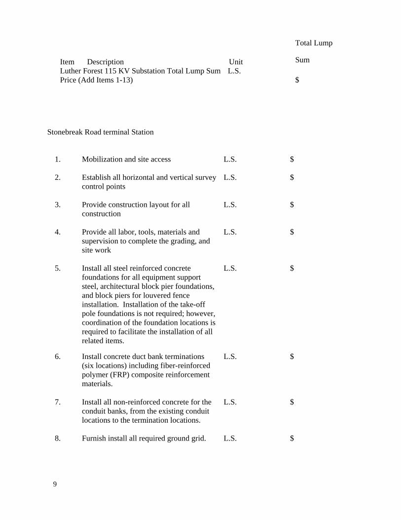
Stonebreak Road terminal Station
1. Mobilization and site access L.S. $ 2. Establish all horizontal and vertical survey
control points L.S. $
3. Provide construction layout for all
construction L.S. $
4. Provide all labor, tools, materials and
supervision to complete the grading, and site work
L.S. $
5. Install all steel reinforced concrete
foundations for all equipment support steel, architectural block pier foundations, and block piers for louvered fence installation. Installation of the take-off pole foundations is not required; however, coordination of the foundation locations is required to facilitate the installation of all related items.
L.S. $
6. Install concrete duct bank terminations (six locations) including fiber-reinforced polymer (FRP) composite reinforcement materials.
L.S. $
7. Install all non-reinforced concrete for the
conduit banks, from the existing conduit locations to the termination locations.
L.S. $
8. Furnish install all required ground grid. L.S. $

10
9. Install the Segmented Retaining wall, including all excavation, backfill, compaction, drainage and geo-grid required as shown on the project drawings and installed per the manufacturer’s specifications.
L.S. $
10. Furnish and install all 8’ high chain link
security fence and posts, including all of the post foundations, grounding and painting per National Grid chain link fence specification dated 5/22/07.
L.S. $
11. Furnish, fabricate and install all Ametco
Venetian Extruded Aluminum Louvered fence and gate as shown on the project drawings including grounding.
L.S. $
12. Site cleanup, seeding, restoration and
demobilization. L.S. $
Stonebreak Road Transition Station Total Lump Sum Price (Add Items 1-12)
L.S. $
Total Sales Tax excluded from all above items (1-13) and (1-12)
L.S. $
LUMP SUM ITEMS The total lump sum price for each item shall include all labor, tools, equipment and materials required to complete the work in its entirety. The total lump sum price shall exclude sales tax. Sales tax shall be identified as a separate line item. The Contractor shall determine his material quantities for each lump sum item based on the elevations, limits and dimensions included in the Contract Specifications, Reference Drawings and/or field measurements. ADDITIONAL ITEMS/WORK NO additional work shall commence without a written Authorization for Contract Change (ACC) by the Owner prior to the start of the additional work. SCHEDULE OF COMMENCEMENT AND COMPLETION Bids will be due June 19th by 4 PM. Anticipated award date will be on or before June 24th. The Contractor agrees if awarded the Contract, that they shall commence the work not later than five (5) calendar days after they receipt of notice to proceed from the Owner. The work shall progress with all reasonable speed and diligence so as to be fully completed on or before

11
September 30, 2009. The Contractor shall submit with his bid a detailed statement of conformance to the specification. The statement shall be of such detail as to illustrate the Contractor’s complete understanding of the work required. The Contractor shall use the scope of work detailed in this specification as a basis for the statement of conformance. It shall indicate all services, which will be provided, and those in which the opinion of the Contractor should be provided but have not been requested. Submittal of the statement of conformance will not relieve the successful Contractor of any responsibilities specified in the construction specification, construction drawings and pre-bid meeting. SUBCONTRACTORS AND SUPPLIERS We plan to use the following subcontractors and suppliers for operations as indicated: Work to be performed
Subcontractor’s & suppliers name & address
Approximate value
The Contractor agrees that this bid is to continue open for acceptance and is irrevocable until 90 days from the Bid Due Date. Name, Signature and Title of Individual Preparing Bid Name of Contractor (Firm, Corporation or Company) Address City, State, Zip Code Telephone

12
ADDITIONS AND DELETIONS Unit prices, inclusive of General conditions, will be used for additions and deletions to the base contract as required. All units are in place costs.
ITEM UNIT ADDITION/DELETION 1. Earth excavation – hand CY 2. Earth excavation – machine CY 3. Rock excavation CY 4. Disposal of excess material CY 5. ¾” crushed stone CY 6. 1 ½” crushed stone CY 7. Select Fill CY 8. Furnish and install duct bank FT. 9. Furnish and install conduit 10. Furnish and install ground grid conductor 11. Furnish and install ground rod 12. Furnish and install ground rod well
FT. FT. FT. FT.
13. Furnish and install riser EA 14. Additional mobilizations EA 15. Additional demobilizations EA
COMPANY NAME SIGNATURE TITLE DATE III. INFORMATION TO BE SUBMITTED
The Contractor shall submit with his bid a detailed bar chart schedule reflecting different phases of work and when each phase will be carried out including dates for critical milestone lead time items. In addition to the bar chart schedule the Contractor shall submit the required bid security and performance bond information. Should the Contractor take exception to the stated dates in the Schedule of Commencement and Completion section then the Contractor shall fill in the following information: Starting Date __________Calendar Days after Written Notification of Award. Construction Duration _________Calendar Days from Start to Contract Completion.
The Contractor shall also submit a fully loaded hourly labor rate schedule for all trades to be utilized on the project along with all hourly equipment rates including operator.
13
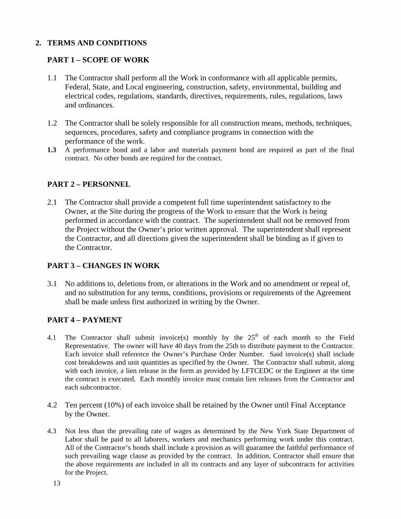
2. TERMS AND CONDITIONS
PART 1 – SCOPE OF WORK 1.1 The Contractor shall perform all the Work in conformance with all applicable permits,
Federal, State, and Local engineering, construction, safety, environmental, building and electrical codes, regulations, standards, directives, requirements, rules, regulations, laws and ordinances.
1.2 The Contractor shall be solely responsible for all construction means, methods, techniques,
sequences, procedures, safety and compliance programs in connection with the performance of the work.
1.3 A performance bond and a labor and materials payment bond are required as part of the final contract. No other bonds are required for the contract.
PART 2 – PERSONNEL 2.1 The Contractor shall provide a competent full time superintendent satisfactory to the
Owner, at the Site during the progress of the Work to ensure that the Work is being performed in accordance with the contract. The superintendent shall not be removed from the Project without the Owner’s prior written approval. The superintendent shall represent the Contractor, and all directions given the superintendent shall be binding as if given to the Contractor.
PART 3 – CHANGES IN WORK 3.1 No additions to, deletions from, or alterations in the Work and no amendment or repeal of,
and no substitution for any terms, conditions, provisions or requirements of the Agreement shall be made unless first authorized in writing by the Owner.
PART 4 – PAYMENT 4.1 The Contractor shall submit invoice(s) monthly by the 25th of each month to the Field
Representative. The owner will have 40 days from the 25th to distribute payment to the Contractor. Each invoice shall reference the Owner’s Purchase Order Number. Said invoice(s) shall include cost breakdowns and unit quantities as specified by the Owner. The Contractor shall submit, along with each invoice, a lien release in the form as provided by LFTCEDC or the Engineer at the time the contract is executed. Each monthly invoice must contain lien releases from the Contractor and each subcontractor.
4.2 Ten percent (10%) of each invoice shall be retained by the Owner until Final Acceptance
by the Owner.
4.3 Not less than the prevailing rate of wages as determined by the New York State Department of Labor shall be paid to all laborers, workers and mechanics performing work under this contract. All of the Contractor’s bonds shall include a provision as will guarantee the faithful performance of such prevailing wage clause as provided by the contract. In addition, Contractor shall ensure that the above requirements are included in all its contracts and any layer of subcontracts for activities for the Project.

14
PART 5 – LIABILITY 5.1 If any act or omission to act on the part of the Contractor or its Subcontractors or any
person under their control causes in whole or part, death or injury to any person, including but not limited to the Owner’s or the Owner’s affiliates’ employees, or any damage to, environmental contamination of, or destruction of any property, including but not limited to property of the Owner or the Owner’s affiliates, the Contractor shall be liable for any claims, losses, damages and costs (including legal expenses) arising there from.
5.2 To the fullest extent permitted by law, the Contractor shall indemnify and hold harmless,
and at the Owner’s option, defend the Owner, its affiliates and their officers, directors, employees, agents, successors, assigns, and servants, from and against any and all claims and/or liability for damage to property, injury or death of any person, including but not limited to, the Contractor’s employees, Subcontractors, and the Subcontractor’s employees, or any other liability incurred by the Owner or its affiliates, including expenses, legal or otherwise, caused wholly or in part, by any act or omission, negligent or otherwise of the Contractor, its Subcontractors and their officers, directors, employees, agents, servants, or assigns, arising out of or connected with the Agreement, regardless of whether caused in part by a party indemnified hereunder.
5.3 To the fullest extent permitted by law, the Contractor shall indemnify and hold harmless,
and at the Owner’s option, defend the Owner and its affiliates and their officers, directors, employees, agents, servants, and assigns from and against any liability, loss, or expense arising by reason of claims by any third party, including, but not limited to, the Contractor’s employees, Subcontractors, and Subcontractors’ employees as a result of the actual or asserted failure, omission, or neglect of the Contractor to comply with the Agreement.
5.4 The obligations under this section shall not be limited in any way by any limitation on the
Contractor’s insurance or by a limitation on the amount or type of damages. In addition, the obligations under this section shall not be limited in any way by any compensation or benefits payable by or for the Contractor or any Subcontractor under worker’s compensation acts, disability benefit acts or other employee acts.
5.5 The Owner shall not be liable to the Contractor for consequential, special, incidental,
multiple, or punitive damages (including attorney’s fees or litigation costs) for performance or non-performance of the Agreement or for any actions undertaken in connection with or related to the Agreement, including without limitation damage claims based on causes of action for breach of contract, tort (including negligence), or any other theory of recovery.
5.6 The Contractor shall at all times conduct operations in a manner to ensure the safety of the
general public and to avoid the risk of loss, theft, or damage by vandalism, sabotage, or any other means. The Contractor shall continually inspect the Project, materials, and equipment to discover and determine any conditions that might involve such risks and shall be solely responsible for discovery, determination, and correction of any such conditions.

15
PART 6 – INSURANCE 6.1 The Contractor shall provide and maintain, at its own expense, insurance policies issued by
reputable insurance companies with an A. M. Best rating of at least B+ that meet or exceed the following requirements:
A. Workers' Compensation and Employers Liability Insurance, as required by New York State.
B. Public Liability, including Contractual Liability and Products/Completed Operations coverage, covering all operations to be performed under this Agreement, with minimum limits of:
1. Bodily Injury - $1,000,000 per occurrence
2. Property Damage - $1,000,000 per occurrence
C. Automobile Liability, covering all owned, non-owned and hired vehicles used under or in connection with this Agreement, with minimum limits of:
1. Bodily Injury - $500,000 per occurrence
2. Property Damage - $500,000 per occurrence
3. Combined Single Limit - $1,000,000 per occurrence
D. Excess Liability or Umbrella Liability – coverage with a minimum per occurrence limit of $5,000,000.
Contractor shall provide certificates of insurance to the Owner evidencing these specified coverages and showing LFTCEDC, NYS Urban Development Corporation dba Empire State Development Corporation and the Town of Malta as an additional insured.
PART 7 – SAFETY
7.1 The Contractor shall be solely responsible and assume all liability for the safety and supervision of its employees and other persons engaged in the Work or on the Site. The Contractor shall establish and effectively and continuously implement a safety program. The Contractor shall, and shall require its Subcontractors and their employees to comply with all applicable Federal, state and local safety directives, requirements, rules, regulations, laws and ordinances, whether the same are in force upon the execution of the Agreement or may in the future be passed, enacted or directed, including without limitation, compliance with the safety regulations and standards adopted under the Occupational Safety and Health Act of 1970 (OSHA), as amended from time to time. The Contractor shall continually inspect the Project and supervise its personnel to determine and enforce compliance with the above provisions.
7.2 The Contractor shall, and shall require its Subcontractors and their employees to comply
with the Contractor’s Safety Requirements and all established Project safety rules as they

16
may be amended from time to time and to take all necessary safety and other precautions to protect property and persons from damage or injury arising out of performance on the Project, whether the same are in force at the execution of this Agreement or may in the future be passed, enacted or directed.
7.3 The Contractor shall provide adequate safeguards, safety devices and protective equipment
and enforce their use and take any other needed actions to protect the life, health and safety of the public and to protect property in connection with its performance on the Project.
7.4 The Contractor shall at its sole expense provide adequate first aid facilities and shall make
those facilities available for the treatment of persons who may be injured or become ill at the Site or while engaged in the performance of Work.
PART 8 – PERMITS, LICENSES, LAWS, AND REGULATIONS 8.1 Permits and licenses of a temporary nature necessary for the prosecution of the Work shall
be secured and paid for by the Contractor. Unless otherwise specified, permits, licenses and easements for permanent structures or permanent changes in existing facilities shall be secured and paid for by the Owner. In either case the Contractor shall be responsible for prosecuting its Work in accordance with the provisions of all applicable permits and licenses.
8.2 The Contractor shall complete the Work so that it complies with all applicable laws, rules,
regulations, requirements, orders, directives, ordinances, codes and standards of all Federal, State, and Local governmental agencies having jurisdiction over the Owner and its affiliates, the Contractor, the Subcontractors, or the Project, whether the same are in force at the execution of this Agreement or may in the future be passed, enacted or directed.
PART 9 – ENVIRONMENTAL PROTECTION 9.1 The Contractor shall comply with all permit conditions, the Owner’s policies set forth in
the Agreement, and all applicable Federal, state and local environmental laws, requirements, orders, directives, rules, regulations, ordinances, and codes whether the same are in force at the execution of this Agreement or may in the future be passed, enacted or directed. The Contractor shall immediately notify the Owner of any citations or notices incurred on the Project and forward copies thereof immediately upon receipt to the Owner.
9.2 The Contractor shall conduct all operations in such a manner to minimize the impact upon
the natural environment and shall comply with all solid waste, hazardous waste, health and safety, notice, training, and environmental protection laws, rules, regulations, requirements, orders, directives, ordinances, codes and standards, of all Federal, State and Local governmental agencies having jurisdiction over the Owner and its affiliates, the Contractor, the Subcontractors, or the Project, whether the same are in force at the execution of this Agreement or may in the future be passed, enacted or directed.
9.4 The Contractor shall provide the owner with Material Safety Data Sheets covering all
materials furnished under or otherwise associated with the work under this agreement, or provide the owner with a document certifying that the Material Safety Data Sheets are not

17
required for each such material. 9.5 If any violation of environmental permits, licenses and other environmental regulations or
statutes occurs, the Contractor shall take immediate action to mitigate any further violation. The Contractor shall immediately notify the owner of the violation.
9.6 The Contractor shall, at its sole expense, defend, indemnify and hold harmless the Owner
and its affiliates and their officers, directors, employees, agents, servants, and assigns from and against all liabilities to third parties (including governmental entities), whether civil or criminal, and all costs and expenses incurred by the Owner, its affiliates, third parties including other contractors and the Contractor as a result of the Contractor’s noncompliance with this Article.
3. SUMMARY OF WORK GENERAL PART 1 - DEFINITIONS Backfill, Common Soil suitable for use as backfill consisting of any mixture of sand
and gravel. Rocks less than 6" in diameter and silt may also be included in the mixture.
Backfill, Select Well-graded gravel, well-graded sandy gravel, or a mixture of
these materials for use as backfill also called Select Borrow. Conservation Seed Mix A mix of annual and perennial grass seed. For local Conservation
Seed Mix contact the Soil & Water Conservation District at (518) 885-6900 ext - 3.
Engineer An entity reporting directly to the Owner responsible for the
engineering design drawings and specifications. Environmental Monitor A person reporting directly to the Owner responsible for
monitoring the Contractor’s environmental compliance and who will provide advice and guidance on issues involving Wetlands.
Field Representative A person reporting directly to the Owner responsible for
monitoring the Contractor’s compliance with the design drawings and specifications.
Materials The components used in the construction of a Project Material Storage Yard An area which is kept secured by the Contractor, and where
Materials are kept after being issued to the Contractor but before
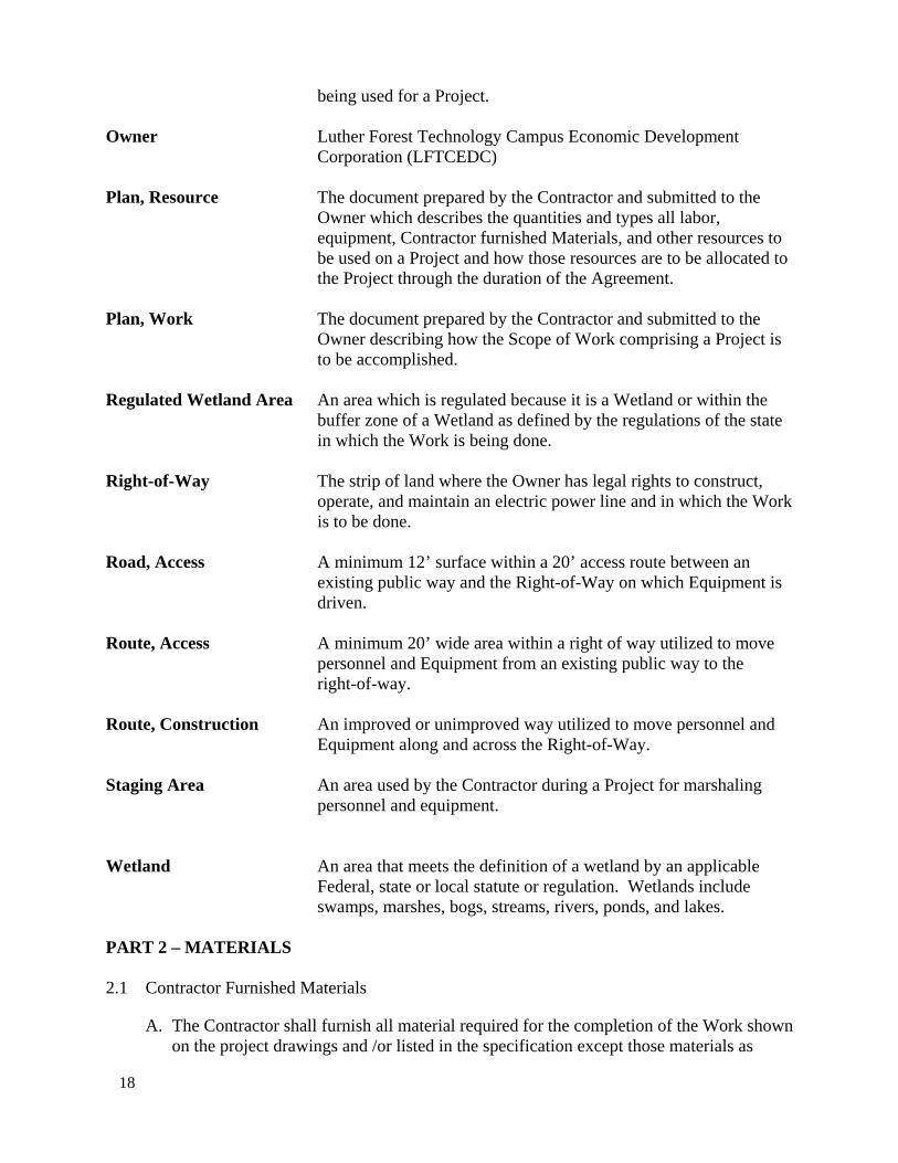
18
being used for a Project. Owner Luther Forest Technology Campus Economic Development
Corporation (LFTCEDC) Plan, Resource The document prepared by the Contractor and submitted to the
Owner which describes the quantities and types all labor, equipment, Contractor furnished Materials, and other resources to be used on a Project and how those resources are to be allocated to the Project through the duration of the Agreement.
Plan, Work The document prepared by the Contractor and submitted to the
Owner describing how the Scope of Work comprising a Project is to be accomplished.
Regulated Wetland Area An area which is regulated because it is a Wetland or within the
buffer zone of a Wetland as defined by the regulations of the state in which the Work is being done.
Right-of-Way The strip of land where the Owner has legal rights to construct,
operate, and maintain an electric power line and in which the Work is to be done.
Road, Access A minimum 12’ surface within a 20’ access route between an
existing public way and the Right-of-Way on which Equipment is driven.
Route, Access A minimum 20’ wide area within a right of way utilized to move
personnel and Equipment from an existing public way to the right-of-way.
Route, Construction An improved or unimproved way utilized to move personnel and
Equipment along and across the Right-of-Way. Staging Area An area used by the Contractor during a Project for marshaling
personnel and equipment. Wetland An area that meets the definition of a wetland by an applicable
Federal, state or local statute or regulation. Wetlands include swamps, marshes, bogs, streams, rivers, ponds, and lakes.
PART 2 – MATERIALS 2.1 Contractor Furnished Materials
A. The Contractor shall furnish all material required for the completion of the Work shown on the project drawings and /or listed in the specification except those materials as

19
specifically indicated to be supplied by the owner..
B. All Materials shall be of good quality and new, except as otherwise provided in the Specifications. If required by the Owner, the Contractor shall furnish satisfactory evidence (including reports of required tests) as to the kind and quality of Materials and equipment. All Materials shall be applied, installed, connected, erected, used, cleaned and conditioned in accordance with the instructions of the applicable supplier except as otherwise provided in the Specifications.
C. If Materials are specified by using the name of a proprietary item or the name of a particular manufacturer, fabricator, supplier or distributor, the naming of the item is intended to establish the type, function and quality required. Unless the name is followed by words indicating that no substitution is permitted, Materials or equipment of other manufacturers, fabricators, suppliers or distributors may be accepted by the Owner if sufficient information is submitted by the Contractor to allow the Owner to determine that the Materials or equipment proposed are equivalent to that named.
D. The Contractor shall provide certificates for Materials furnished by the Contractor which demonstrate proof of compliance with applicable Specifications or Drawings. Each certificate shall be executed in three (3) copies and shall be signed by an authorized official of the manufacturing company. Each certificate shall show the name and address of the Contractor, the Project title and location and the quantity and dates of shipments or deliveries to which the certificates apply. Certification shall not be construed as relieving the Contractor from furnishing satisfactory Materials if subsequent tests show that the Materials do not meet the specific requirements.
E. The Contractor shall submit shop drawings to the Field Representative for approval prior to beginning fabrication or installation of any of the Contractor furnished Material. Shop drawings shall be submitted in three (3) copies. Approval of shop drawings shall not be construed as relieving the Contractor of the responsibility of furnishing satisfactory Materials. Manufacturers’ literature and drawings shall be submitted for all items which the Contractor is to supply.
F. The procedure for review by the Owner of requests for substitute items will be as set forth in the following paragraphs.
1. Requests for review of substitute items of Materials and equipment will not be accepted by the Owner from anyone other than the Contractor. If the Contractor wishes to furnish or use a substitute item of Material or Equipment, the Contractor shall make written application to the Owner for acceptance thereof, certifying that the proposed substitute will perform adequately the functions called for by the general design, be similar and of equal substances to that specified and be suited to the same use and capable of performing the same function as that specified. The application shall state whether or not acceptance of the substitute for use in the Work shall require a change in the Drawings or Specifications to adapt the design to the substitute and whether or not incorporation or use of the substitute in connection with the Work is subject to payment of any license fee or royalty. All variations of the proposed substitute from that specified shall be identified in the application and available maintenance, repair and replacement service will be indicated.
20
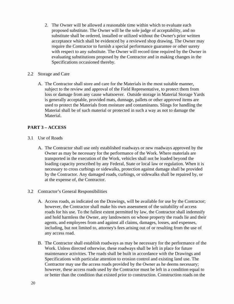
2. The Owner will be allowed a reasonable time within which to evaluate each proposed substitute. The Owner will be the sole judge of acceptability, and no substitute shall be ordered, installed or utilized without the Owner's prior written acceptance which shall be evidenced by a reviewed shop drawing. The Owner may require the Contractor to furnish a special performance guarantee or other surety with respect to any substitute. The Owner will record time required by the Owner in evaluating substitutions proposed by the Contractor and in making changes in the Specifications occasioned thereby.
2.2 Storage and Care
A. The Contractor shall store and care for the Materials in the most suitable manner, subject to the review and approval of the Field Representative, to protect them from loss or damage from any cause whatsoever. Outside storage in Material Storage Yards is generally acceptable, provided mats, dunnage, pallets or other approved items are used to protect the Materials from moisture and contaminants. Slings for handling the Material shall be of such material or protected in such a way as not to damage the Material.
PART 3 – ACCESS 3.1 Use of Roads
A. The Contractor shall use only established roadways or new roadways approved by the Owner as may be necessary for the performance of the Work. Where materials are transported in the execution of the Work, vehicles shall not be loaded beyond the loading capacity prescribed by any Federal, State or local law or regulation. When it is necessary to cross curbings or sidewalks, protection against damage shall be provided by the Contractor. Any damaged roads, curbings, or sidewalks shall be repaired by, or at the expense of, the Contractor.
3.2 Contractor’s General Responsibilities
A. Access roads, as indicated on the Drawings, will be available for use by the Contractor; however, the Contractor shall make his own assessment of the suitability of access roads for his use. To the fullest extent permitted by law, the Contractor shall indemnify and hold harmless the Owner, any landowners on whose property the roads lie and their agents, and employees from and against all claims, damages, losses, and expenses, including, but not limited to, attorney's fees arising out of or resulting from the use of any access road.
B. The Contractor shall establish roadways as may be necessary for the performance of the Work. Unless directed otherwise, these roadways shall be left in place for future maintenance activities. The roads shall be built in accordance with the Drawings and Specifications with particular attention to erosion control and existing land use. The Contractor may use the access roads provided by the Owner as he deems necessary; however, these access roads used by the Contractor must be left in a condition equal to or better than the condition that existed prior to construction. Construction roads on the
21
right-of-way shall be routed by the Contractor subject to the approval of the Field Representative. Stream and wetland crossings by roads shall be made where shown on the Drawings. Roads shall be routed to avoid prohibited areas such as "no vehicular access areas," archeological and historical areas, and trails not available for use as shown on the Drawings.
C. Discharge of dredged or fill material into waters of the United States or their adjacent wetlands other than the required fill roads, fords, culverts, mat roads, bridges, and structure pads shown on the Drawings shall not be allowed. Waters of the United States include inland rivers lakes, streams, and wetlands.
D. Access roads and construction roads shall be maintained by the Contractor through completion of the Work.
E. Public roads subject to interference by the operations of the Contractor shall be kept open or detours shall be provided at the expense of the Contractor. The Contractor shall provide, erect, and maintain all necessary barricades, sufficient red light warning and danger signals, and signs and shall take all necessary precautions for the protection of the Work and the safety of the public, all in accordance with the requirements of the applicable officials. Highways and roads closed to traffic or under repair shall be protected by effective barricades on which shall be placed approved warning and detour signs. Signs shall be placed, in clear view, at all points of ingress and egress to public and well traveled private roads. All barricades and obstructions shall be illuminated or reflectorized at night and all lights shall be kept burning from sunset until sunrise.
F. The Contractor shall brief all his personnel concerning the location of areas prohibited to vehicular equipment and wetlands and the requirement that vehicles and equipment, other than hand held, are not allowed in these areas.
G. Town Roads
It is the Contractor's responsibility to coordinate the use and upgrading of town roads with the appropriate town. The Contractor shall adhere to all requirements set forth by local governing authorities.
PART 4 – ENVIRONMENTAL PROTECTION 4.1 The Contractor shall make every reasonable effort to perform the Work in a manner which
will minimize adverse impacts to the environment. 4.2 The Contractor shall be responsible for monitoring the Work and its compliance with
environmental laws, rules, regulations, ordinances, codes, orders of condition, and standards of all local, state, and Federal governmental agencies having jurisdiction over the Work and with the provisions of the Agreement.
4.3 The Contractor shall provide the Field Representative with the name and 24-hour telephone
number(s) of the person with responsibility for ensuring compliance seven days prior to the commencement of Work.

22
4.4 Erosion Control
A. The Contractor shall prevent soil erosion resulting from the Work. The method(s) of controlling soil erosion shall be subject to the review and approval of the Field Representative.
B. Siltation and erosion control materials acceptable to the Owner must be kept on Site at all times.
C. Installation of controls shall be in accordance with the Drawings. 4.5 Wetlands
A. General
No changes in grade, permanent removal of vegetation, or changes in hydrology are authorized within Wetlands.
B. Operation of Equipment within Wetlands
1. The operation of vehicles traveling in Wetlands shall be confined to existing Access and Construction Routes to the maximum extent possible.
2. Any vehicles used by the Contractor in Wetlands shall be operated on swamp mats or below-ground-pressure tracked vehicles or low-ground-pressure wide-tire vehicles unless otherwise directed by the Environmental Monitor and Field Representative. Swamp mats shall be constructed of wood that has not been treated with any preservative, unless otherwise approved by the Owner. Low-ground-pressure vehicles are defined as those whose average ground pressure does not exceed 650 pounds per square foot.
3. Ruts created by low-ground-pressure vehicles may not exceed six inches in depth, and vegetation may not be excessively disturbed without the approval of the Environmental Monitor and the Field Representative.
4. If, when using vehicles in a Wetland, ruts in excess of six inches in depth are created or excessive disturbance of vegetation occurs, the use of such vehicles shall immediately be stopped. The Environmental Monitor and Field Representative shall then direct the steps to be implemented to repair and mitigate rutting.
5. The use of multiple Access or Construction Routes within a Wetland in order to increase the number of vehicle trips through a Wetland without swamp mats are not authorized.
6. Fuel, oil, and hazardous materials shall not be stored within 100 feet of Wetlands. Field refueling, equipment, and prevention of spillage shall all be strictly in compliance with the requirements of the applicable section(s) of this Specification.
7. Equipment containing petroleum or hazardous materials may not be left unattended in Wetlands during non-working hours unless the Equipment is on swamp mats and
23
unless leaving the Equipment is authorized by the Environmental Monitor and Field Representative.
C. Erosion and Sedimentation Control
1. The Contractor shall protect against erosion or sedimentation of soil into Wetlands resulting from the Work.
2. At all Work Sites and Construction and Access Routes located in Regulated Wetland Areas where top soil is expected to be disturbed, erosion and sedimentation controls consisting of hay bales and/or siltation fence shall be installed in accordance with the Drawings prior to the disturbance of the top soil. These controls are required even under frozen ground conditions.
3. No excavated material shall be placed directly into a Wetland. Excavated material that is to be used as backfill may be temporarily stockpiled on geotextile fabric or a swamp mat adjacent to the Work Site if properly protected by erosion and sedimentation controls. Neither excess excavated material nor geotextile fabric may be left in a Wetland after work at a Work Site is complete. Methods of removing excess excavated material from Wetlands shall be subject to the review and approval of the Environmental Monitor and Field Representative. In areas adjacent to - but not in - Wetlands, excess excavated material may be spread around the Work Site with the approval of the Environmental Monitor and Field Representative. Natural drainage channels shall not be blocked.
4.6 Archeological and Historical Objects
The Contractor shall immediately notify the Field Representative if any suspected archeological or historical objects are identified during performance of the work. The Field Representative will advise the Contractor on the mitigation measures that will be necessary.
4.7 Noise Control
The Contractor shall control noise at all times to the extent possible. Air compressors shall be equipped with silencers and the exhaust of all gasoline engines and other power equipment shall be provided with mufflers.
4.8 Dust Control
The Contractor shall control nuisance dust by applying water and/or a dust palliative, other than calcium chloride, for the alleviation or prevention of dust nuisances caused by construction operations. The Contractor shall operate vehicles to minimize dust nuisances.
4.9 Equipment
A. Equipment shall be in good working order, be properly maintained, and be properly operated.
B. Equipment shall not leak fluids.

24
C. Smoke from equipment shall be minimized at all times to the extent possible. 4.10 Prevention of Spillage
Chemicals, fuels, oils, greases, bituminous materials, solids, waste washing, concrete or similar substances used in construction operations shall be properly stored and handled to prevent accidental spills and contamination of surface waters and ground waters. Oil spill kits and other appropriate remedial supplies shall be kept on-site at all times and on each vehicle at all times.
4.11 Field Refueling and Maintenance Operations
A. Refueling
Refueling shall not take place in Regulated Wetland Areas or in or within 100 feet of environmentally sensitive areas such as Wetlands or drinking water sources. Refueling should be done on a paved area if possible. Refueling operations shall be continuously monitored for fuel spills, drips, or seeps. If spills, drips, or seeps occur, refueling operations shall be stopped until the source is found and repaired. All spills or drips of fuel shall be properly cleaned up.
B. Grease, Oil, and Filter Change
Routine maintenance lubrication and oil changes shall not take place in Regulated Wetland Areas or within 100 feet of environmentally sensitive areas such as Wetlands and drinking water sources. Lubrication and oil changes should be done on a paved area if possible. All reasonable environmental and safety precautions shall be taken. Waste oil and lubricants shall be collected and properly disposed of. All spills and drips of grease or oil shall be properly cleaned up.
C. Other Field Maintenance Operations
Other vehicle or equipment maintenance operations shall not take place in or within 100 feet of environmentally sensitive areas such as Wetlands or drinking water sources if at all possible. Maintenance operations should be performed on a paved area if possible. If the maintenance operations must be done in or within 100 feet of an environmentally sensitive area, extraordinary precautions shall be taken to prevent oil or hazardous material from being released to the environment. These precautions include, but are not limited to, use of portable basins or similar secondary containment devices, use of ground covers such as plastic tarpaulins, and precautionary placement of floating booms on nearby surface water bodies. If the maintenance operations will be done away from an environmentally sensitive area, all reasonable environmental and safety precautions shall be taken.
4.12 Temporary Facilities
The Contractor shall provide all temporary facilities required for the Work covered in this specification including but not limited to temporary power, office trailer, telephone, water and toilets. Portable, self-contained chemical toilets shall be provided for all workers when
25
permanent toilets are not available. The portable toilets shall be maintained and cleaned regularly and wastes shall be properly disposed of.
PART 5 – CLEAN-UP AND RESTORATION 5.1 Clean-up
The Contractor shall at all times during the progress of the work keep all construction areas, including Staging Areas and Material Storage Yards, free from removed materials, waste material, and rubbish. Materials, waste material, and rubbish removed from the construction areas shall be properly disposed of.
5.2 Restoration
Unless otherwise specified below, Work Site and Right-of-Way restoration of disturbed areas shall be completed as soon as possible after the work is performed. If the work is to be done in phases, the disturbed area must be stabilized between phases so as to not degrade further.
5.3 Restoration/Clean-up Standards
A. Unless otherwise specified below, all disturbed areas, including Wetlands and Access and Construction Routes, shall be returned to original grade, seeded with a Conservation Seed Mix, and mulched with hay.
B. Yards, lawns, agricultural areas, and other improved areas shall be returned to a condition at least equal to that which existed at the start of the Project.
C. Access Roads and Construction Roads shall be returned to a condition at least equal to that which existed at the start of the Project except that Access and Construction Roads shall, at a minimum, be serviceable for four-wheel drive vehicles. Ruts shall be removed from Access and Construction Roads. Seeding and/or mulching of Access or Construction Roads is not required unless necessary to prevent erosion.
D. All damage to property occurring as a result of a project shall be immediately repaired or replaced. In some locations, it may be desirable to document preexisting damage prior to the project in order to demonstrate afterwards that the damage did not result from the Project.
E. After all work is completed; swamp mats and temporary bridges shall be removed. Removal of swamp mats and temporary bridges must be done in accordance with the Environmental Protection section of this Specification.
F. After all work has been satisfactorily completed and vegetation has been reestablished, and upon approval by the Environmental Monitor and Field Representative, all siltation fence shall be removed, stakes from hay bales shall be removed, and the strings on the hay bales cut and properly disposed of. Hay bales which were used for sedimentation or siltation control may be used to mulch disturbed areas. Remaining hay bales which do not block the flow of water may be left in place. Hay bales which block the flow of
26
water must be moved. Siltation fence and hay bale stakes shall be disposed of properly off site.
G. Any stone wall removed or breached by construction activities shall be repaired or rebuilt, unless directed otherwise by the Field Representative. Rebuilt stone walls shall be placed on the same alignment that existed prior to temporary removal.
H. After all work has been satisfactorily completed, the Contractor shall remove all work-related trailers, buildings, rubbish, waste soil, temporary structures, and unused materials belonging to him or used under his direction during construction, or waste materials from previous construction and maintenance operations. All areas shall be left clean and restored to a stable condition and where feasible, as near as possible to its original condition, as determined by the Field Representative.
I. Upon completion of all Work, all Material Storage Yards and Staging Areas shall be completely cleared of all waste and debris. Unless otherwise directed or unless other arrangements have been made with an off right-of-way land owner, Material Storage Yards and Staging Areas shall be returned to the condition which existed prior to the installation of the Material Storage Yard or Staging Area. Whether or not arrangements have been made with a land owner, all areas shall be left in an environmentally sound condition. Also any temporary structures erected by the Contractor, including fences, shall be removed by the Contractor and the area restored as near as possible to its original condition, including possibly seeding and mulching.
PART 6 – RIGHTS AND PERMITS 6.1 Right-of-Way Easements
A. The Owner shall obtain all easements and rights-of-entry required for the Work unless otherwise noted in this Specification.
B. The rights obtained by the Owner include the right to erect, maintain and remove structures, cables, and other appurtenances. Any other activities proposed by the Contractor shall be subject to the review and approval of the Field Representative.
6.2 Highway Traffic Control
Unless otherwise stated, the Contractor shall arrange for local and state highway traffic control and flag protection and inspection, as required.
6.3 Dig Safe
A. The Contractor shall determine the locations of all existing power, communication and pipeline facilities within the Project areas in accordance with applicable laws and regulations. It shall consult with the respective agencies or owners and make all necessary provisions to avoid interference with the operation and maintenance of such facilities to the satisfaction of the Owner.
B. The Contractor shall notify: Dig Safely NY and obtain a Dig Safe number for all

27
locations where the existing ground, public or private, within or outside the Site, will be disturbed in any way. The Contractor shall perform pre-marking, if required. The Contractor shall be aware that many municipal utilities do not participate in the Dig Safe program and shall contact each applicable municipal utility as appropriate.
PART 7 – CONTRACTOR YARDS 7.1 Material Storage Yards
A. The Contractor shall acquire rights for and construct any facilities required for Material Storage Yards. Rights-of-way and land owned by the Owner may not be used for Material Storage Yards. The Contractor shall submit copies of all signed agreements securing rights from landowners for Material Storage Yards. The Owner reserves the right to direct the Contractor to modify Material Storage Yards or provide additional Material Storage Yards.
B. The locations of Material Storage Yards shall be subject to the review and approval of the Field Representative. Material Storage Yards shall not be located in or within 100’ of Regulated Wetland Areas.
C. The Contractor shall maintain the Material Storage Yards in an orderly and clean condition. The Contractor shall remove snow from the aisles within the yards to keep them accessible at all times.
D. The Material Storage Yards must be adequate in size to store both the Owner furnished Materials and Contractor furnished Materials.
7.2 Staging Areas
A. The Contractor shall construct any facilities required for Staging Areas. All Staging Areas on the Right of Way are subject to the review and approval of the Field Representative. The Contractor shall acquire the rights to construct off Right-of-Way Staging Areas. The Contractor shall submit signed copies of all agreements securing rights from landowners for off Right-of-Way Staging Areas.
B. The locations of Staging Areas shall be subject to the review and approval of the Field Representative. Staging Areas shall not be located in or within 100’ of Regulated Wetland Areas.
PART 8 – POWER, COMMUNICATION AND PIPELINE FACILITIES 8.1 The Contractor shall determine the locations of all existing power, communication and
pipeline facilities within the Project areas in accordance with applicable laws and regulations. It shall consult with the respective agencies or owners and make all necessary provisions to avoid interference with the operation and maintenance of such facilities to the satisfaction of the Field Representative.
PART 9 – EXCAVATION

28
9.1 Excavation The Contractor shall do all grubbing, soil and rock excavation, drilling, forming, sheathing, shoring, trenching, pumping, and draining required for proper installation of the Work. Excavation shall be done with appropriate Equipment with the excavation size being minimized.
A. Classification of excavated material shall be as follows:
1. Rock excavation - Rock shall be defined as:
(a) All solid or ledge rock which cannot, in the opinion of the Field Representative, be removed by standard excavation Equipment and which requires the use of jack hammers, breaker points or other methods for excavation.
(b) Boulders or portions thereof where the excavation volume of the whole boulder or portion thereof exceeds one-quarter cubic yard, and where such boulder or portion thereof cannot, in the opinion of the Field Representative, be removed by standard excavation Equipment and which requires the use of jack hammers, breaker points, or other methods for excavation.
2. Common excavation - shall mean all material which is not, by definition, rock excavation.
3. All loose or disturbed soil or rock shall be removed from the bottom of excavations.
4. All excess excavated material shall be disposed of in areas approved by the Field Representative. The Contractor shall submit a disposal plan to the Field Representative for approval prior to the start of excavation.
5. All open excavations shall be covered or protected in such a manner that livestock, pets, and people cannot fall into the excavation nor can persons easily remove the covers or protection.
B. Control of Water
Since there is often a presence of a high water table, the Contractor shall be responsible for having readily available such pumps, hose lines, and other Equipment as may be required to control water inflow and to dewater excavations prior to and during placement of concrete.
If there is adequate vegetation in upland areas to function as a filter medium, the water generally will be discharged to the vegetated land surface. Where adequate vegetation is absent or where slope prohibits, water will be pumped into a temporary hay bale dewatering basins which will be located in approved areas outside wetland resource areas. Such temporary dewatering basins, as detailed on the drawings, shall be installed as directed by the Field Representative, and are incidental to the Work. The pump intake hose will not be allowed to set on the bottom of the excavation throughout dewatering. The basin and all accumulated sediment will be removed following dewatering operations and the area will be seeded and mulched.
29
PART 10 – SUBMITTALS
10.1 The Contractor is responsible for compiling (6) copies of all required submittals per the submittal
schedule below. All submittals shall be distributed to the Engineer of Record “TRC” for review and approval prior to work commencing. The following is a schedule of submittals required:
1. Heating and cooling calculations of the Control Building 2. Heating and cooling equipment catalog cuts identifying the loading and supply voltages. 3. Complete set of Control Building drawings, including but not limited to:
Foundation Plan, Roof sections, Wall Sections, Cable Trench entrance details, Lighting Plan, General purpose electrical plan and receptacles for all building loads, Fire alarm system, Security system
4. Ametco Venetian extruded aluminum vertical louvered fence panels and gate 5. Proposed concrete design mix and supplier 6. Reinforcing bar cage drawings 7. Communication hand hole and cover
PART 11 – CLOSEOUT REQUIREMENTS
11.1 The Contractor is responsible for providing to the owner at completion of the project a full closeout binder to include all warranties (manufacturer and contractor), as built drawings, owner and operator manuals, daily reports, testing reports, photographs, etc. Final payment will not be released to the Contractor until receipt and acceptance of all closeout documentation provided.

Page 1 of 12
DUCT BANK PART 1 – GENERAL 1.1 Conditions
A. The terms and requirements of the Contract Documents apply to all the work of this section. A qualified contractor with experience installing electric transmission duct banks will be required for this project. Qualifications and previous experience of the proposed contractor shall be supplied as part of the proposal for review and approval by National Grid.
1.2 Work Included
A. The Contractor shall provide and install two concrete encased duct banks, each one consisting of nine (9) 6 inch PVC conduits in two concrete encased duct banks consisting of 3 high by 3 wide arrangements. As the duct bank approaches each manhole each duct bank will split into 3 high by 1 wide and 2 wide by 3 high and enter on opposite sides of the manhole.
B. The Contractor shall provide and install two concrete encased duct banks, each one consisting of nine (9) 6 inch Fiberglass Reinforced Epoxy (FRE) conduits in a 3 high by 3 wide arrangements installed in two existing 48 inch inside diameter concrete reinforced pipes approximately 85 feet in length that have been previously installed under Vettura Court at Park Place. The FRE conduits shall be installed with FRE to PVC fittings on both ends and the pipe shall be filled by pumping concrete grout or flowable thermal backfill to fill all voids between conduits and the inside walls of the 48 inch concrete sleeves.
C. The duct banks shall be installed between Malta Substation and the proposed manhole locations on Stonebreak Road adjacent to Route 9 as shown on the Drawings. Warning tape shall also be installed in each trench approximately 12’ - 18” above the duct bank.
D. Concrete, grout and flowable thermal backfill used to encase the conduits shall be sampled and tested for thermal resistivity. Concrete shall have a thermal resistivity of less than 90 Degree C cm/watt at 0% moisture content.
E. Two man holes will be installed, one in each duct bank, in the locations shown on the drawings. 3 conduits shall be installed on one side of each man hole and 6 conduits will be installed on the opposite side of each man hole.
F. The Contractor shall stub and plug conduits at each end of contract limits as shown on the Drawings.
G. The minimum cover over the duct bank from finish grade to top of concrete shall be 3 feet in all locations.
H. Concrete truck washout areas shall be located or constructed so as to not adversely

Page 2 of 12
affect water resources. PART 2 – MATERIALS 2.1 General
A. The Contractor shall provide all materials to make a complete duct bank system as set forth in this specification.
2.2 Duct banks
A. Polyvinyl Chloride (PVC) Conduit shall be 6 inch, schedule 40 one belled end per length, solvent welded. Fittings shall consist of straight, 5 degree and manhole bell ends. PVC conduit and fittings shall satisfy requirements of ASTM F512, latest revision.
Fiberglass Reinforced Conduit (FRE) shall be 6 inch Iron Pipe Size (IPS), medium wall (nominal 0.1inch wall thickness); Conduit shall be provided in 20 foot lengths, with one belled end per length. For duct bank construction, a concrete tight and water tight bell end (gasketed interference joint) shall be provided.
Transition from PVC conduit to FRE conduit shall be with the FRE manufacturers recommended couplings, either factory installed on the FRE conduit (preferred) or field installed.
B. Conduit spacers shall be molded high-impact polystyrene sized for 6 inch conduit. Spacers should provide 2 inches of separation between adjacent conduits and 3 inches of separation between the bottom row of conduits and the trench bottom. Spacers shall be Carlon “Snap and Stack SP6W20 Series” or Carlon 6” base and intermediate conduit spacers or Engineer accepted equivalent.
C. Warning tape shall be 6 inches wide, 4 mils thick plastic. Tape shall be red in color with black printed message “CAUTION: BURIED ELECTRIC LINE BELOW”.
D. Jackmoon blank plugs sized for 6 inch conduit, Jackmoon part 60D637U.
E. The riser ends at the termination stations shall be fiberglass reinforced epoxy (FRE) conduit and 6 foot radius FRE riser sweeps.
PART 3 – EXECUTION 3.1 Trench Preparation
A. The trench bottom shall be solid, undisturbed earth. Earth showing excessive signs of peat, cinders, rubble, frozen material, or any conditions not suitable for a stable foundation shall be removed and replaced with compacted gravel (maximum stone size is 2 inches).

Page 3 of 12
B. Where the earth walls of the trench are firm enough to sustain themselves, and all OSHA requirements are met, the trench walls may be used as the forms for concrete encasement. The walls of these trenches shall be carefully trimmed to allow the proper thickness (minimum of 3 inches) of concrete around the outside conduits, but shall not be so wide as to require an excessive amount of concrete to fill the trench. If shoring and/or sheeting are necessary, they shall be placed as required to maintain the excavation and shall be removed prior to concrete encasement and/or as the backfilling progresses so that all shoring is removed as the job is completed.
3.2 Defective Conduit
A. Defective or broken conduits shall not be installed and shall be removed immediately from the site of the work.
3.3 Separation between Adjacent Facilities:
A. A minimum of 12 inches of clearance shall be maintained between the concrete encasement and an adjacent utility, unless allowed by Owner.
3.4 Jointing of Conduits
A. All field cut conduit ends shall be cleanly square cut. All conduit ends that will be inserted into a belled fitting (whether into another section of conduit or into any form of coupling) shall be internally chamfered to a 45 degree angle to approximately half the conduit wall thickness. This shall be performed with a router equipped with a bearing guided 45 degree chamfering bit.
B. Joints shall be unthreaded solvent cement type. The contact surfaces of the conduit and fitting socket shall be cleaned, liberally coated with the conduit manufacturer’s recommended solvent cement, promptly and fully engaged, and either conduit or fitting rotated approximately ¼ turn to dispel air and evenly distribute solvent cement over contact surfaces.
C. For proper connection, total elapsed time between the start of the cement application to the surfaces being joined and final assembly of the joint should not exceed 60 seconds. The initial strength of the joint shall permit continuous conduit installation; however, additional stress at the joint shall be avoided for at least 24 hours after joining.
Duct joints for PVC to FRE and for FRE to FRE shall be in accordance with the FRE manufacturer’s recommendations.
D. The duct bank shall be constructed with bell & spigots installed in one consistent direction. When a direction of cable pull has been specified on the Drawings, the duct bank shall be constructed so that all bell ends face into the direction of the pull (cable pulled into the bell end). If no direction of pull has been specified, then the duct bank shall be constructed so that all bell ends face the same direction. This direction of construction shall be marked on the Drawings and provided to the Owner.

Page 4 of 12
3.5 Conduit Bending
A. Field bends shall not be constructed with a radius of curvature less than the minimum radii as shown on the construction prints. Unless specifically shown on the construction plans, duct line bends of less than 40 foot radius are not allowed. Should site conditions require tighter radius bends, the Engineer shall be notified to evaluate these bends before they are constructed.
B. For large radius bends, PVC conduit has the ability to be bent without any heating of the material. Hot bending of the conduit is strictly prohibited.
C. Bends that are tighter than can be cold bent, down to approximately a 15 foot radius, shall be made using 5 degree couplings. An approximate segment length between couplings for various bend radii is shown in the attached table. The contractor shall determine the required length of conduit between single 5 degree couplings to yield the required radius of curvature using the table as a guide. Five degree couplings must have a length of straight conduit installed between successive couplings.
D. Bends with a radius between 7 and 15 feet shall be constructed using flexible conduit. Flexible conduit shall be Arnco SMOOTH-COR® flexible conduit or Engineer accepted equivalent.
E. Bends of a five or six foot radius shall be constructed using manufactured FRE sweeps. 3.6 Concrete Encasement
A. Intermediate and base spacers for 2 inches separation between ducts and 3 inches beneath ducts shall be installed for all conduit runs. Intermediate spacers shall be used as caps on the top tier. Spacers shall be installed at 5 - 8 foot intervals and shall be placed at each coupling.
B. The concrete envelope shall be poured after the individual ducts are securely tied in place and adequately anchored and/or weighted to completely counteract the buoyancy of the ducts in the fluid concrete.
C. No ferrous (steel or iron) containing material that could create a complete metallic path around any single conduit or combination of conduits shall be used in the installation of the duct bank. Specifically the use of steel conduit / couplings, steel rebar cages, metallic tie wraps and metallic tie wire is strictly prohibited. Conduits may be secured to duct bank spacers using plastic or nylon tie wraps.
D. If the interval between concrete pours is expected to exceed 2 hours, then #4 reinforcing bars 6 feet long shall be installed in the corners and between ducts on the top and bottom rows. The reinforcing bars shall be installed parallel to the lengths of the individual conduits. Metallic tie wraps or tie wire shall not be used to secure the reinforcing bars to the duct bank.
3.7 Spare / Stubbed Conduit

Page 5 of 12
A. Conduit which is stubbed shall be plugged prior to backfilling and shall remain plugged until the conduit is extended later (by others). Concrete encasement shall stop approximately 12 inches from the end of the stubbed conduit.
3.8 Backfill
A. Concrete will be cured for a minimum of 2 hours prior to backfilling.
B. Backfill within 6 inches of the top of the concrete shall be free of solid material greater than 4 inches maximum dimension or with sharp edges likely to cause damage. The balance of the backfill shall be free of solid material greater than 8 inches maximum dimension. Backfill material shall be adequately compacted in 6 inch lifts. Peat, cinders, rubble and frozen material are not suitable backfill material.
3.9 Warning Tape
A. Warning tape shall be installed 12-18 inches below finished grade and directly above the concrete encasement.
3.10 Final Acceptance
A. The Contractor shall prove the duct bank by pulling a close fitting flexible mandrel through each conduit. The mandrel test will be witnessed by the National Grid Field Construction Coordinator (FCC). The mandrel’s outer diameter shall be approximately ¼ inch less than the conduit nominal inside diameter. Should any conduit not prove successfully, the Contractor shall repair / replace any conduits that do not successfully pass the mandrel.
B. The Contractor shall clean the conduits by pulling a wire brush and swab, sized for 6 inch conduit, through each conduit. Upon completion of these steps, the Contractor shall present the conduit as suitable for cable pulling.
C. The Contractor shall equip each conduit with a 2500 lb rated polyester pulling tape, Arnco DLWP25, NEPTCo WP2500P or Engineer accepted equivalent. This is provided for the cable installation contractor’s convenience only, and is not intended for cable pulling use.
D. The Contractor shall plug the end of the conduit with a Jackmoon blank plug or Owner accepted alternate.
E. The Contractor shall provide the owner with a set of as built plans. Horizontal and vertical deviations from the plans shall be accurately noted on the as builts. The as built plans shall provide the location and elevation of the top of the concrete encased duct banks at 100 foot stations, at all bends, and at all changes in depth of bury.

Page 6 of 12
MANHOLES PART 1 – GENERAL 1.1 Precast concrete manufactured manholes are to be designed to AASH0-HS20-44 direct
wheel loading 1.2 Manhole chimney shall be a minimum of two layers of brick to allow for future grade
changes. Where required to increase height of manhole opening either brick or precast concrete may be used.
1.3 A 36 inch manhole frame with a 26 to 36 inch manhole ring and a 26 inch manhole cover
shall be used for new construction.
A. Furnishing Material - Any material required to be furnished by the contractor shall comply with National Grid Material Specifications.
B. Preparation For Installation - Fill bottom of excavated hole with a minimum of 1 foot of well compacted crushed bank gravel.
C. Foreign Structures - All parts of the manhole structure should have at least 6 inches clearance from all pipes and structures.
D. Duct Entrances - Duct entrances shall be constructed such that end bells are flush with manhole walls.
1. Formation – Project plans specify the duct entrance formation and size required.
2. Relative Location – Ducts with staggered alignment are to have opposite formations on opposite walls.
3. Bell ends shall be used on all ducts entering the manhole.
E. Placing Frame, Ring and Cover - Mound concrete around top of chimney and cover base of frame with one inch of grout.

Page 7 of 12
CONCRETE PART 1 – GENERAL 1.1 General Use reinforced and plain concrete, when job specifications are not being issued. 1.2 Materials
A. Cement shall be a standard brand of Portland Cement Type II conforming to ASTM C150. If concrete is to be in contact with sea water or soils other than clean gravel, of if job conditions require earlier strength development than Type II provides, notify Engineer for use of a higher strength or high-early strength concrete.
B. Sand shall be sharp and clean and shall conform to ASTM C33, latest revision.
C. Coarse aggregate shall be of gravel, crushed gravel or crushed stone and conform to ASTM C33, latest revision.
D. Water shall be from a potable water supply or tested and approved by Engineer assuring it is clean and free from injurious amounts of oil, acids, alkali, organic materials, or other harmful substances.
1.3 Ready-Mix Concrete
A. Ready-mix concrete shall be proportioned at the plant. Mixing and delivery shall be in accordance with ASTM C94, latest revision. Mixes shall conform to Table 6 for minimum 28 day strength, nominal maximum size aggregate, and slump.
B. An air-entraining agent shall be added to concrete mixes in which the surface will be exposed to the elements. No other admixtures shall be used without approval of Engineer. Air-entrainment content shall be as follows:
Table 5
Mix M2 and M3: 7.0% plus or minus 2.0% Mix M4: 5.0% plus or minus 1.5% Mix M5: 4.5% plus or minus 1.5% Mix M6: 6.0% plus or minus 1.0%
C. The purchaser reserves the right to make tests at any time on materials used and concrete furnished by the ready-mix concrete supplier. The batch plant, equipment, and operating procedures are subject to inspection and approval by Engineer or their qualified representative.
Table 6

Page 8 of 12
Concrete Mixes
Mix Number Strength Minimum 28 Day (Lbs./Square Inch)
Aggregate Maximum Size Nominal
Slump Not More Than Typical Applications
M1 2,000 1-½” 2” Bedrock and Floor Fill M2 2,000 ½” 2” Duct Lines – Tier Method M3 2,000 ½” 6” Duct Lines – Unit Method
M4 3,000 1-½” 2” Footings, Slabs on Ground, Foundation Walls, and Pile Caps
M5 3,000 1” 2” Floor and Roof Slabs on Forms
M6 4,000 1” 2” Hi-Strength Slabs and Walls
Note: If a greater slump in required, contact Engineer for an additive to meet the specific job requirements.
D. Ready-mix concrete shall be ordered in accordance with this Section. The cubic yards, delivery point, time schedule, and applicable mix number for the particular application shall be specified on the order.
E. Delivery of a concrete batch in excess of the rated mixer drum capacity is cause for rejection. The latest drum inspection certificate should be available for verification.
1.4 Delivery and Mixing
A. In the event that delivery of concrete is called for when the air temperature is below 40 degrees Fahrenheit, the following shall apply:
1. When the air temperature is between 30 degrees Fahrenheit and 40 degrees Fahrenheit, the concrete shall be delivered in excess of 55 degrees Fahrenheit.
2. When the air temperature is between 0 degrees Fahrenheit and 30 degrees Fahrenheit the concrete shall be delivered at a temperature in excess of 60 degrees Fahrenheit.
B. In hot weather concrete shall be delivered at a temperature which will not cause difficulty from loss of slump, flash set, or cold joints. Discharge of concrete at the job site shall be completed within one hour of adding the mixing water.
1.5 Forms
A. Formwork shall be designed and constructed in accordance with the American Concrete Institute’s “Recommended Practice For Concrete Formwork”, ACI 347, of latest date.
B. Forms shall be built substantially; true to form, lines, dimensions, and grades shown. They shall be braced and tied to maintain position and shape, without yielding to

Page 9 of 12
pressure of fluid concrete or other forces, including those produced by vibratory compaction.
C. Forms shall be constructed of ¾ inch BB grade plywood supported with 2 x 4 studs on 16 inch centers. Forms shall not exceed a 10 foot pour height and form tie spacing shall not exceed 2 feet. Form ties and accessories, manufactured by Richmond Screw Anchor Company or equal, shall be used. Prefabricated forms are allowed after approval by Engineer. The forms shall be vertical and symmetrical and in the largest sizes practicable. Sheets showing torn grain, worn edges, hole patches, or other defects, which impairs the texture of the concrete surface, shall not be used.
D. Forms shall be treated with approved form oil, before erection or reinforcing steel placement, to prevent adhesion of the concrete.
E. Forms shall be mortar-tight. For surfaces which will be exposed, the form faces shall be smooth and mortar-tight.
F. Forms shall be removed carefully to avoid damage to the concrete surfaces. The removal time is governed by the concrete’s condition, curing temperature, curing time, and the forces the new concrete may be subjected. Under favorable curing conditions, forms may be removed no sooner after placement than the following:
1. 7 days for supported floor and roof slabs
2. 48 hours for wall and columns
3. 24 hours for footing walls and piers
4. 12 hours for underground duct lines
G. If high-early strength concrete is used, the above time periods may be reduced by one-half.
H. These periods presented are the cumulative number of days or fractions thereof, not necessarily consecutive, during which the concrete temperature is above 50 degrees Fahrenheit. Whenever formwork is removed during the curing period, the exposed concrete shall be repaired immediately, finished, and cured as specified under Section 7.
1.6 Placement
A. Concrete shall not be placed until the forms, previously poured concrete surfaces, reinforced steel, and embedded parts have been cleaned of laitance, loose or defective concrete, soil on rock surface, and any other foreign materials.
B. All concrete placed when the air temperature is above 45 degrees Fahrenheit shall be placed at the coolest temperature as practicable. Concrete placement is not permitted when hot weather conditions prevent proper placement and consolidation. Concrete will not be accepted if its temperature is in excess of 80 degrees Fahrenheit.
Page 10 of 12
C. When the mean daily temperature falls below 40 degrees Fahrenheit, the minimum concrete temperature shall be 55 degrees Fahrenheit and as close to this minimum as possible.
D. When the air temperature is below 40 degrees Fahrenheit, provide suitable protection so the concrete can be maintained at a minimum of 50 degrees Fahrenheit throughout the curing period. The protection and heat source, shall maintain the required temperature and moisture conditions without injury due to concentration of heat. All materials which the concrete contacts such as reinforcing, forms, ground, etc., shall be free of frost prior to placement.
E. Concrete temperature changes during and immediately following the curing period shall be as uniform as possible and shall not exceed 5 degrees Fahrenheit in any one hour, or 40 degrees Fahrenheit in any 24 hour period. When heaters are used, prevent local surface heating and drying and provide adequate ventilation to prevent carbonation damage to exposed concrete surfaces. Thermostatic temperature controls shall be provided to control the heated enclosures to 50 degrees Fahrenheit. Temperatures exceeding 80 degrees Fahrenheit are to be avoided.
F. Concrete shall not be allowed to fall from the end of a chute, tube, or bucket more than 5 feet to point of deposit and shall have a fall free from obstructions. Chutes shall be metal or metal lined. Pumping equipment, pipelines, procedures, etc., shall be in accordance with ACI 304R, latest revision, and Engineer shall be consulted for mix design of any pumped application. Conveying equipment for pumped concrete shall be of suitable kind, without “Y” sections and with adequate pumping capacity. No aluminum pipe shall be used. Placement shall be controlled so there is no separation in the discharged concrete. The maximum loss of slump in pumping equipment shall be 1½ inches.
G. Concrete shall be deposited as near to its final position as possible to avoid long flows in the forms. Concrete shall not be moved more than 10 feet from point of deposit. Concrete shall be placed in successive horizontal layers, ranging in thickness from 6-15 inches, maximum. Concrete shall be placed within 1½ hours after addition of cement to the aggregate.
H. Where conditions make it difficult to place concrete uniformly and perform compaction at the bottom of forms, batches of mortar containing the same proportion of cement to sand as in the concrete mix shall be deposited first and spread over the cleaned surface to a depth of approximately 1 inch.
I. Segregated, unworkable, and excessive slump concrete shall not be placed or, if placed, shall be removed and wasted as directed. High slump concrete resulting from addition of approved additives is acceptable for placement. Free water accumulating on new concrete during placement shall be removed as directed by the Engineer.
J. Placement and compaction methods shall ensure homogeneous concrete with maximum consolidation without segregation. Consolidate concrete by internal vibration, spading, or rodding by working it thoroughly around reinforcement, embedded items, and into corners of forms to eliminate all air or stone pockets which cause honeycombing,

Page 11 of 12
pitting, or planes of weakness. Concrete contacting all formed surfaces shall be spaded manually to eliminate air bubbles.
K. Place horizontal construction joints at uniform vertical spacing unless otherwise shown on the drawings. Concrete shall not be placed to a depth of more than 10 feet in any 24 hour period, unless approved by Engineer. All concrete placements shall be such as to keep cold joints from forming.
L. Whenever work is suspended on any section for more than one hour, the horizontal edges of the concrete next to the forms shall be brought to a plane perpendicular to the form face, and treated so no irregular, rough, or feathered edge joints show in the finished work. Before placing the next lift, clean the joint surface and remove all laitance. Immediately before placing new concrete wet the joint surface and remove all standing water.
M. Unless adequate weather protection is provided, do not place concrete during rain, sleet, or snow.
1.7 Curing
A. Protect freshly deposited concrete from premature drying and hot or cold temperatures. Maintain a constant temperature throughout the curing period without drying.
B. All exposed concrete surfaces shall be kept continuously moist overnight by ponding, sprinkling, or by use of an approved membrane type curing compound, which conforms to ASTM C309, latest revision, and applied in conformance with the manufacturer’s recommendations.
C. Curing shall continue, using one of the above methods or waterproof paper, for a 7 day period (3 days for high-early strength concrete) maintaining the concrete at a minimum temperature of 50 degrees Fahrenheit as is practical. Protective covering with tarpaulins, hay, straw, etc. shall be provided to retard moisture evaporation during hot weather and to prevent rain damage before hardening. Protective covering shall be available for immediate use at all times.
D. During the curing period, the concrete shall be protected from damaging mechanical disturbances, particularly load stresses, heavy shock, and excessive vibration.
1.8 Surface Finish
All surface fins shall be removed. Exposed concrete surfaces shall not be given any special treatment to enhance appearance, such as rubbing with a stone, without permission of Engineer.
1.9 Loading of Concrete
A. Normal concrete structures shall not be subjected to external loads in less than:
1. Four days for foundations, manhole floors, and walls.

Page 12 of 12
2. Seven days for floors, roofs, and columns. Each concrete placement shall be allowed to set 48 hours before addition of a subsequent pour upon it. If high-early cement is used this time period may be reduced by one-half.
B. Trenches containing concrete encased duct lines constructed on undisturbed original ground may be backfilled not less than two hours after placement. Compaction by light tamping equipment may proceed immediately. Loading of the backfill by heavy equipment or traffic is not permitted before 12 hours after placement.
1.10 Waterproofing
Waterproofing is provided by the density of the concrete mix and the thickness of concrete. Care must be used in placing and compacting the concrete to eliminate all voids and potential leakage paths. When structures less than 8 inches thick must be waterproof, consult Engineer to revise the mix design to achieve the desired waterproof result.
Note: If a greater slump is required, contact Engineer for an additive to meet the specific job requirements.

Luther Forest Station Control Bldg. Outline Specification
1
CONTROL BUILDING
GENERAL
Building can be of masonry or prefabricated metal construction and shall be equipped with fully functional electrical distribution and HVAC equipment. Building shall have minimum interior dimensions as shown on the drawings. The roof system shall be provided with a minimum one (1) inch per foot pitch side-to-side to prevent accumulation of water. The roof shall be designed to prevent water and ice buildup on protruding equipment. Overhangs/gables shall be provided as required. The structure shall be designed and constructed in accordance with Fire and Building Codes of New York State and shall meet the Energy Conservation Code of New York State with an "R" rating of 22 for insulation and an "R" rating of 30 for the ceiling and roof insulation. The enclosure shall have a one-hour fire rating on all wall, floor and roof construction. Interior walls shall be capable of supporting/mounting a minimum 250lbs/ft equipment load at random locations on the wall. Equipment locations are shown on the drawings. All interior materials, devices and equipment installed shall meet all required standards and shall be installed per National Electrical Code. A certificate of approval issued by New York Board of Fire Underwriter (NYBFU) or other qualified Electrical Inspection Agency shall be required. Structural Steel - All work shall conform to the applicable provisions of the latest edition of the American Institute of Steel Construction (AISC), Fabrication and Erection of Structural Steel for Building, American Welding Society (AWS), Steel Structures Painting Council (SSPC), Steel Joist Institute (SJI) and Steel Deck Institute. Shop coat paint shall be a rust inhibitive primer subject to Owner approval. Minimum design loading shall be larger of: Snow Loading: ASCE-7, Latest Edition Floor Loading: 150 PSF Wind Loading: Walls: ASCE-7, Latest Edition Roof: ASCE-7, Latest Edition Eaves: ASCE-7, Latest Edition Cable Tray: (Walls & Ceiling) 75 PLF per tray (There are multiple layers of
trays at certain locations in the control building.) or Per Fire Prevention Code and Building Code of New York State All drawings and designs must be stamped and approved by a N.Y.S. Licensed registered professional engineer. The Contractor shall furnish three (6) sets of prints of building drawings and catalog cuts for all equipment/materials to the Owner for review.
Luther Forest Station Control Bldg. Outline Specification
2
DESIGN During conceptual design a copy of the control building drawing will be sent to the Owner to ensure that the design adequately reflects the design requirements. No construction will start until the Owner or their authorized representative approves the drawing. At the completion of the design and prior to acceptance by the owner, all the drawings and designs must be stamped and approved by N.Y.S. licensed registered professional engineer. CONSTRUCTION During construction of the control building,all work and materials shall at all times be open to the inspection, acceptance or rejection by the Owner.
EXTERIOR
FOUNDATIONS
DESIGN
1. All work shall conform to the applicable provisions of the latest edition of the American Concrete Institute (ACI) Codes. 4,000psi 28-day compressive strength concrete shall be used as a minimum.
2. Concrete testing shall be the responsibility of the contractor. A copy of all concrete mix designs
and test results shall be submitted to the Owner. However, the Owner reserves the right to acquire the services of another testing firm to verify test results.
3. The bearing base for any footing and slab shall be on undisturbed soil or fill materials beneath
the footing compacted to minimum 95% modified proctor density. Test results shall be required for each foundation and shall be submitted to the Owner for approval. However, the Owner reserves the right to acquire the services of another testing firm to verify test results.
4. Expansion joint material between concrete slabs and footing shall be required. 5. Footing shall be poured concrete, uniform and designed for the approved total design loads. The
exterior footing walls shall be insulated on interior face with a 2" perimeter insulation board. Exposed concrete footing walls are to be free of protrusions, pin holes, etc., to provide a smooth finished concrete surface.
6. A vapor barrier of .006 inches (6 mils) polyethylene shall be provided under slab. Steel trowel
finish shall be the required surface for the concrete slab if it is to be the building floor. A floor hardener shall be applied to slab surface.
7. In the control building there are four cable trench entrances which will need to be incorporated
into the foundation design.

Luther Forest Station Control Bldg. Outline Specification
3
WALLS
GENERAL Exterior Walls Exterior wall construction may be of standard weight concrete masonry units. Block shall be sealed and waterproofed with a decorative exterior wall finish. Exterior walls may be of 20 gauge galvanized G90 steel if a prefabricated building is used.
DESIGN
Masonry
All workmanship and materials shall be in accordance with the Building Code requirements for Concrete Masonry Structures (ACI 531) latest edition and ASTM standards referenced therein.
Construction Requirements:
1. Environmental Conditions
Antifreeze liquids, salts and other similar substances shall not be used in the mortar mix.
2. Concrete Masonry Units (CMU) Exterior and interior CMU shall have smooth faces both sides.
3. Mortar
Mortar shall be freshly prepared and uniformly mixed.
Testing:
A. Compressive strength of the mortar and grout shall be determined by the test method
described below at an age of 7 and 28 days. B. Build and test a minimum of two (2) sets of samples (3 cubes each) using the materials and
workmanship being employed at the job site. C. Sampling construction and testing shall conform to the requirements of ASTM C109. D. No reinforcing steel shall be placed in the specimens. E. The test report shall be submitted to the Owner for acceptance and shall include the level of
load (psi) at the appearance of the first detectable crack. An interim report giving the 7-day compressive strength of the mortar shall be provided immediately upon completion of the 7-day compressive tests.

Luther Forest Station Control Bldg. Outline Specification
4
4. Joint Reinforcement
Materials
A. Horizontal masonry joint reinforcement shall utilize truss design “Dur-O-waL” reinforcing. Hot-dip galvanized reinforcing shall be employed for exterior walls and mill-galvanized shall be used on all interior applications. Extra heavy class shall be used on load bearing walls and standard class on non-load bearing walls.
B. Wall ties for unit masonry securement to steel frame shall be ¼ inch diameter galvanized
VEE type #VWT as manufactured by Hohman & Barnard or equivalent by “Dur-O-waL.” C. Bond beams shall employ standard unit concrete masonry with Section 04220 utilizing grade
60 deformed steel reinforcing bars. D. Pre-fabricated or job-fabricated corner and tee sections shall be used to form continuous
reinforcement around corners and for anchoring abutting walls and partitions. Material in corner and tee sections shall correspond to type and design of reinforcement used.
E. Wall openings: unless otherwise noted, Dur-O-waL shall be installed in the first and second
bed joints, 8 inches apart immediately above lintels and below sills at openings and in bed joints at 16 inch vertical intervals elsewhere. Reinforcement in the second bed joint above or below openings shall extend 2 feet beyond the jambs. All other reinforcement shall be continuous except it shall not pass through vertical masonry control joints.
F. Control joints: unless otherwise noted, all reinforcement shall be continuous except it shall
not pass through vertical masonry control joints.
Thermal and Moisture Protection Building Insulation - Vapor Barrier
6. Wall Insulation
Walls shall meet the Energy Conservation Code of New York State.
7. Surface Bonding Cement Coating
Exterior masonry surfaces shall be waterproofed utilizing a factory-packaged mixture of Portland cement base. Physical properties and workability shall be equal to structural skin. Color to be selected by the Owner.
8. Wall Caulking and Sealant
The items to be caulked include: Interior and exterior control joints in masonry walls. Exterior hollow metal doorframes (inside and outside). Interior hollow metal door frames and masonry walls. Wall louvers/masonry interface. Exterior exhaust vents/masonry interface. Horizontal joint between metal siding and masonry

Luther Forest Station Control Bldg. Outline Specification
5
Prefabricated Metal
Exterior walls shall be painted with a 20 year durability finish. Color to be approved by the Owner. The fastening system shall be designed so that no wall fasteners are exposed on the exterior. The floor system shall be coordinated with the foundation design. Interior Walls The interior wall separating Control Room #1 and Control Room #2 shall be complete from floor to roof and have a 1 hour fire rating. All penetrations through this wall except for the cable tray, shall be adequately sealed for a 1 hour fire rating upon completion. At each cable trench entrance, there shall be a partial concrete block wall for supporting and guiding the cable tray into the cable trench per the drawings.
DOORS
Exterior Door Frames Channel Frames: Channel frames are the preferred choice for all exterior doors. Channel frames up to 8’-0” shall be minimum C6x13. Larger channel frames to be determined based on door size. Frames to be powder coated (color to be determined by the Owner) and templated to receive door hardware specified prior to field installation. Hollow Metal Frames: Where hollow metal frames are used for exterior applications, they shall be 14 gauge, galvanized, welded, double rabbitted with plaster guards for specified hardware. Masonry anchors with one additional top anchor all locations. Frames to be set square braced then filled with mortar during wall construction. Hollow metal frames shall be set in accordance to manufactures printed instructions for masonry construction.
Note: If exterior hollow frames are required to be fire rated, then each frame shall show the manufacturers “UL-Label” clearly displayed for rating specified.
Exterior Doors Exterior door construction shall have the following minimum requirements listed below.
1. 16 gauge galvanized steel primed/finished painted. Door construction shall be urethane bonded
or vertical “H” stiffened with batt insulation to achieving a minimum “U” value of 0.14. Honeycomb door construction or manufacturer’s “seconds” are not acceptable.
2. Full flush seamless construction including door head. 3. Internal reinforcements as specified by door hardware schedule.
Each Control Room shall have a pair of out swing equipment access doors.

Luther Forest Station Control Bldg. Outline Specification
6
Equipment Access Doors Each pair of out swing doors shall be a minimum of 7’-0”W x 8’-6”H. The active leaf shall be 3’-0”W x 8’-6”H and the inactive leaf shall be 4’-0”W x 8’-6”H. The inactive leaf shall be secured with top and bottom surface mounted bolts. No closer or locksets required. Active leaf shall have overlapping weather-stripped astragal (see door hardware section), door closer and surface mounted vertical rod exit device. Provide one piece solid threshold and fully weather-stripped. Man Doors Two man doors for general personnel access and four man doors for cable trench/cable tray access are required as a minimum. Provide additional doors for general access to building if required by code. These doors shall be an out swing single leaf door (3’W x 7’H) complete with door closer, rim mounted exit device, one piece solid threshold and fully weather-stripped. Doors and frames shall be prepared in accordance with the following: • Mortise, reinforce, drill and tap to receive hardware specified herein. Universal cutouts for
hardware not acceptable. • Provide steel reinforcing for door hardware; 8 gauge for hinges (hollow metal frames with
additional top hinge reinforcement) and doors respectively, 12 gauge for lock and strike in door and frame and 10 gauge for closure.
• Provide cover boxes in back of frames for specified hardware. • Welding of butts in frames not permitted. • Self-tapping and sheet metal screws for attaching hardware not permitted, except for Kick Plates
and weather-stripping. • Active leaf, on paired doors, with welded on 14gauge astragal.
Finish Hardware
1. *Keying: Cylinders shall be master keyed to National Grid’s Best Lock Figure “8” Coring
System. The Developer shall supply all locks with temporary construction cores for use. Master keyed cores shall be supplied directly to the owner. The Owner will change cores after project acceptance and return construction cores to The Developer. Four (4) construction master keys shall be required. 2. Finish Hardware: Items of finished hardware shall be as listed below: US32D, as noted, for
exterior and US26D for interior applications.
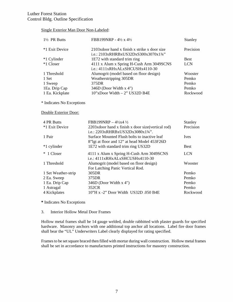
Luther Forest Station Control Bldg. Outline Specification
7
Single Exterior Man Door Non-Labeled: 1½ PR Butts FBB199NRP - 4½ x 4½ Stanley
*1 Exit Device 2103xdoor hand x finish x strike x door size
i.e.: 2103xRHRBxUS32DxS300x3070x1¾” Precision
*1 Cylinder 1E72 with standard trim ring Best *1 Closer 4111 x Alum x Spring H-Cush Arm 3049SCNS LCN i.e.: 4111xRHxALxSHCUSHx4110-30 1 Threshold Alumogrit (model based on floor design) Wooster 1 Set Weatherstripping 305DR Pemko 1 Sweep 375DR Pemko 1Ea. Drip Cap 346D (Door Width x 4") Pemko 1 Ea. Kickplate 10”xDoor Width – 2” US32D B4E Rockwood
* Indicates No Exceptions
Double Exterior Door: 4 PR Butts FBB199NRP – 4½x4 ½ Stanley *1 Exit Device 2203xdoor hand x finish x door size(vertical rod)
i.e.: 2203xRHRBxUS32Dx3080x1¾”. Precision
1 Pair Surface Mounted Flush bolts to inactive leaf 8”lgt at floor and 12” at head Model 453F26D
Ives
*1 cylinder 1E72 with standard trim ring US32D Best
* 1 Closer 4111 x Alum x Spring H-Cush Arm 3049SCNS i.e.: 4111xRHxALxSHCUSHx4110-30
LCN
1 Threshold Alumogrit (model based on floor design) For Latching Panic Vertical Rod.
Wooster
1 Set Weather-strip 305DR Pemko 2 Ea. Sweep 375DR Pemko 1 Ea. Drip Cap 346D (Door Width x 4") Pemko 1 Astragal 352CR Pemko 4 Kickplates 10”H x -2” Door Width US32D .050 B4E Rockwood
* Indicates No Exceptions 3. Interior Hollow Metal Door Frames
Hollow metal frames shall be 14 gauge welded, double rabbitted with plaster guards for specified hardware. Masonry anchors with one additional top anchor all locations. Label fire door frames shall bear the “UL” Underwriters Label clearly displayed for rating specified. Frames to be set square braced then filled with mortar during wall construction. Hollow metal frames shall be set in accordance to manufactures printed instructions for masonry construction.
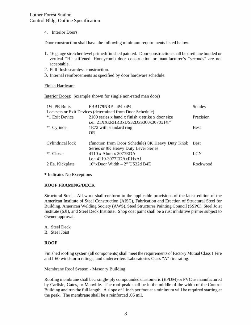
Luther Forest Station Control Bldg. Outline Specification
8
4. Interior Doors
Door construction shall have the following minimum requirements listed below. 1. 16 gauge stretcher level primed/finished painted. Door construction shall be urethane bonded or
vertical “H” stiffened. Honeycomb door construction or manufacturer’s “seconds” are not acceptable.
2. Full flush seamless construction. 3. Internal reinforcements as specified by door hardware schedule. Finish Hardware Interior Doors: (example shown for single non-rated man door) 1½ PR Butts FBB179NRP - 4½ x4½ Stanley Locksets or Exit Devices (determined from Door Schedule) *1 Exit Device 2100 series x hand x finish x strike x door size
i.e.: 21XXxRHRBxUS32DxS300x3070x1¾” Precision
*1 Cylinder 1E72 with standard ring Best OR Cylindrical lock (function from Door Schedule) 8K Heavy Duty Knob
Series or 9K Heavy Duty Lever Series Best
*1 Closer 4110 x Alum x 3077EDA i.e.: 4110-3077EDAxRHxAL
LCN
2 Ea. Kickplate 10”xDoor Width – 2” US32d B4E Rockwood
* Indicates No Exceptions
ROOF FRAMING/DECK Structural Steel - All work shall conform to the applicable provisions of the latest edition of the American Institute of Steel Construction (AISC), Fabrication and Erection of Structural Steel for Building, American Welding Society (AWS), Steel Structures Painting Council (SSPC), Steel Joist Institute (SJI), and Steel Deck Institute. Shop coat paint shall be a rust inhibitive primer subject to Owner approval.
A. Steel Deck B. Steel Joist
ROOF Finished roofing system (all components) shall meet the requirements of Factory Mutual Class 1 Fire and I-60 windstorm ratings, and underwriters Laboratories Class "A" fire rating. Membrane Roof System - Masonry Building Roofing membrane shall be a single-ply compounded elastomeric (EPDM) or PVC as manufactured by Carlisle, Gates, or Manville. The roof peak shall be in the middle of the width of the Control Building and run the full length. A slope of 1 inch per foot at a minimum will be required starting at the peak. The membrane shall be a reinforced .06 mil.
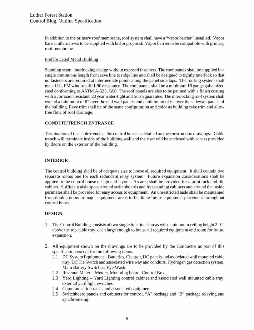
Luther Forest Station Control Bldg. Outline Specification
9
In addition to the primary roof membrane, roof system shall have a “vapor barrier” installed. Vapor barrier alternatives to be supplied with bid or proposal. Vapor barrier to be compatible with primary roof membrane. Prefabricated Metal Building Standing seam, interlocking design without exposed fasteners. The roof panels shall be supplied in a single continuous length from eave line to ridge line and shall be designed to tightly interlock so that no fasteners are required at intermediate points along the panel side laps. The roofing system shall meet U.L. FM wind-up lift I-90 resistance. The roof panels shall be a minimum 18 gauge galvanized steel conforming to ASTM A-525, G90. The roof panels are also to be painted with a finish coating with a corrosion resistant, 20 year water-tight and finish guarantee. The interlocking roof system shall extend a minimum of 8” over the end wall panels and a minimum of 6” over the sidewall panels of the building. Eave trim shall be of the same configuration and color as building rake trim and allow free flow of roof drainage.
CONDUIT/TRENCH ENTRANCE
Termination of the cable trench at the control house is detailed on the construction drawings. Cable trench will terminate inside of the building wall and the riser will be enclosed with access provided by doors on the exterior of the building.
INTERIOR
The control building shall be of adequate size to house all required equipment. It shall contain two separate rooms one for each redundant relay system. Future expansion considerations shall be applied to the control house design and layout. An area shall be provided for a print rack and file cabinet. Sufficient aisle space around switchboards and freestanding cabinets and around the inside perimeter shall be provided for easy access to equipment. An unrestricted aisle shall be maintained from double doors to major equipment areas to facilitate future equipment placement throughout control house. DESIGN
1. The Control Building consists of two single functional areas with a minimum ceiling height 2’-0”
above the top cable tray, each large enough to house all required equipment and room for future expansion.
2. All equipment shown on the drawings are to be provided by the Contractor as part of this
specification except for the following items: 2.1 DC System Equipment – Batteries, Charger, DC panels and associated wall mounted cable
tray, DC Tie Switch and associated wire way and conduits, Hydrogen gas detection system, Main Battery Switches, Eye Wash.
2.2 Revenue Meter – Meters, Mounting board, Control Box. 2.3 Yard Lighting – Yard Lighting control cabinet and associated wall mounted cable tray,
external yard light switches 2.4 Communication racks and associated equipment 2.5 Switchboard panels and cabinets for control, “A” package and “B” package relaying and
synchronizing.
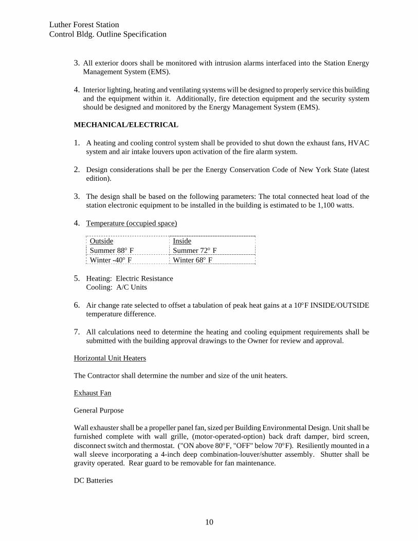
Luther Forest Station Control Bldg. Outline Specification
10
3. All exterior doors shall be monitored with intrusion alarms interfaced into the Station Energy
Management System (EMS). 4. Interior lighting, heating and ventilating systems will be designed to properly service this building
and the equipment within it. Additionally, fire detection equipment and the security system should be designed and monitored by the Energy Management System (EMS).
MECHANICAL/ELECTRICAL
1. A heating and cooling control system shall be provided to shut down the exhaust fans, HVAC
system and air intake louvers upon activation of the fire alarm system. 2. Design considerations shall be per the Energy Conservation Code of New York State (latest
edition). 3. The design shall be based on the following parameters: The total connected heat load of the
station electronic equipment to be installed in the building is estimated to be 1,100 watts.
4. Temperature (occupied space)
Outside Inside Summer 88° F Summer 72° F Winter -40° F Winter 68° F
5. Heating: Electric Resistance Cooling: A/C Units 6. Air change rate selected to offset a tabulation of peak heat gains at a 10°F INSIDE/OUTSIDE
temperature difference. 7. All calculations need to determine the heating and cooling equipment requirements shall be
submitted with the building approval drawings to the Owner for review and approval. Horizontal Unit Heaters
The Contractor shall determine the number and size of the unit heaters.
Exhaust Fan General Purpose Wall exhauster shall be a propeller panel fan, sized per Building Environmental Design. Unit shall be furnished complete with wall grille, (motor-operated-option) back draft damper, bird screen, disconnect switch and thermostat. ("ON above 80°F, "OFF" below 70°F). Resiliently mounted in a wall sleeve incorporating a 4-inch deep combination-louver/shutter assembly. Shutter shall be gravity operated. Rear guard to be removable for fan maintenance. DC Batteries
Luther Forest Station Control Bldg. Outline Specification
11
An exhaust fan, located above each battery, is required for battery ventilation. Specific requirements will be provided later. Intake Louvers Intake louvers shall be aluminum combination damper/louver type, storm proof, 6" depth, motor-operated damper to open, spring return close (power off) with insect screen and galvanized finish. Size as required per Building Environmental design requirements. Lighting Units Exterior Exterior control building lights are required. Refer to the drawings for quantity, type and location. Interior Provide fluorescent lighting units, with lamps, surface mounting with ceiling spacer. Control house is to be designed for 70 foot-candle minimum of light at 3 feet above the floor vertical and 30 foot-candle minimum of light on the face of each equipment lineup. Emergency Lights Emergency lights are required for each Control Room per the building code. Exit Lights Exit lights are required for each control room per the building code. Wire and Wiring Copper wire for 600 volts shall be soft drawn copper of 98% conductivity. Wires No. 12 AWG and smaller shall be single conductor thermoplastic covered, rated for 75°C. All lighting circuits shall be rated for 90°C. Wire shall be Collyer, Triangel, or Rockbestos-Suprenant Cable Corp. The minimum size permitted will be No. 12 AWG except as follows: Heating and Cooling Controls: per the equipment manufacturer Fire Alarm System: per the equipment manufacturer Security System: per the equipment manufacturer Color code all wires for phase identification shall be as follows: 208 Volt 3 Phase 208 Volt 1 phase 120 Volt ØA – Black ØA – Black ØA – Black ØB – Red ØB – Black Neutral – White ØC – Blue Neutral – White Ground – Green Neutral – White Ground – Green Ground – Green
Luther Forest Station Control Bldg. Outline Specification
12
Duplex Receptacles and Switches Location of receptacles is indicated below: Unless otherwise directed, mounting heights of outlets and equipment shall be as follows: Wall switches: 4' - 0" above finished floor. Convenience outlets: General; 1' - 6" above finished floor, nine (9’-0”) feet apart. All inside receptacles shall be duplex grounded, GFI protected, 20 amp, 125V, 3/W, Brown Nylon Face, Hubbell Catalog Number 5362 or Engineering approved equal, provide submittal for approval. Six (6) outside receptacles shall be duplex grounded, GFI protected, surface mounted (12" above foundation) weatherproof cover, 20 AMP, 125V, 3/W, Brown Face, Hubbell or Engineering approved equal, provide submittal for approval. Cover shall be Weather proof, in the open position, with a 45 degree rain cover. 3-way switches shall be SPECIFICATION GRADE, 120/277V, 20A Brown Toggle. Switches shall be Hubbell Catalog Number 1223 or Engineering approved equal, provide submittal for approval. Refer to the drawings for quantity and location.
CABLE TRAY/WIREWAYS
GENERAL
The Contractor shall be responsible for the procurement of the cable tray systems and shall be subject to owner review and acceptance. DESIGN Cable trays will be required for routing low voltage power, control and instrumentation cables which enter from yard cable trenches and cables routed within Control Building. Cable tray assembly shall be NEMA Class 12B (75 lbs. per linear foot for maximum span of 12 feet) consisting of horizontal and vertical lengths and elbows, supporting hangers, splice plates and mounting hardware as shown on drawings. All trays are to be aluminum, 6" deep (outside) ladder type with 9" rung spacing and widths as shown on drawing. A 4/0 soft drawn copper conductor shall run the entire length of the cable tray system and shall be bonded to each section of tray. Connect tray ground to the building ground bus. T.J. Cope, Inc. or BLine, no substitutions.
Cable tray design should be based upon the required loading and the maximum spacing between supports. Loading should include the static weight of cables and a concentrated load of 200 pounds at mid span. The tray load factor (safety factor) should be at least 1.5 based on collapse of the tray when supported as a simple beam. All cable tray systems shall not exceed 50 percent fill except as necessary at intersections and where cables enter or exit the cable tray systems.
Luther Forest Station Control Bldg. Outline Specification
13
The Contractor is responsible for the cable tray as follows: There shall be three horizontal levels of cable tray in the building. Cable trays A1 and A2 are 12” wide trays which are primarily dedicated for AC and DC power circuits. These trays are mounted at 12’-0” (to the tray bottom above finished floor) and do not penetrate the interior wall. Cable trays B1 and B2 are 9” wide trays which are primarily dedicated for “A” and “B” system interconnect cables. These trays are mounted at 10’-6” (to the tray bottom above finished floor) and will connect through penetrations in the interior wall. Cable trays C1 and C2 are 30” wide trays and are dedicated for control cables. These trays are mounted at 9’-0” (to the tray bottom above finished floor) and do not penetrate the interior wall. Both trays will have two vertical sections in the interior of the building to bring all cables down to the cable trenches. Various size cable trays with covers shall be mounted vertically above the AC power panels ACPP#1A, 1B, 1C, 2, 2A and 2B. These trays are intended to route AC power cables from the panels to cable trays A1 and A2. Cable trays are to be labeled with 1 3/4’ wide x 2 7/8” high, reflective, adhesive lettering. Background color shall be yellow and legend color shall be black. Label wording is noted on the drawings.
TELEPHONE GENERAL
Telephone Company circuits will be fed into the control house through entrance facility conduit. Two separate plywood telephone backboards (one in each control room) shall be installed in the Control Building to terminate circuits coming through the new conduits. The Contractor shall provide two 4’-0”H x 8’-0”W x 3/4”D equipment mounting boards, painted ANSI 61 grey, mounted horizontally on the control building wall. Refer to the drawings for locations.
DESIGN
Telephone Company Entrance
A 4" schedule 40 PVC conduit, riser and floor penetration shall be installed for present and future telephone cables. A floor penetration large enough for the 4” Schedule 40 PVC will be provided near the telephone board. The conduit shall run from the control house to an accessible point outside the finished stone edge of the substation.
GROUNDING
GENERAL
The station Control Building and all equipment within will be grounded according to National Grid and NEC Standards.
Luther Forest Station Control Bldg. Outline Specification
14
DESIGN
Provisions to be provided for a #4/0 soft copper ground wire riser from the station ground grid to enter the Control Building at six points per the drawings. The #4/0 copper ground wire shall connect to the 2" X 1/4" copper ground bar that encircles each Control Room 13’-6” above finished floor (maximum) on insulated spacers allowing space from the wall to make connections. This ground bus will provide shielding for the Control Building. All ground connections to wall-mounted cabinets and equipment grounds will terminate here. Building steel shall be bonded and grounded.
All interior conduits, boxes and other non-current carrying metal parts of electrical equipment, building steel and neutrals shall be grounded in accordance with NEC Standards.
Cable trays will have one (1) #4/0 soft copper ground wires run the entire length of the tray system. This #4/0 soft copper ground wires shall be attached to each section of cable tray. All power and lighting circuits will include a separate ground conductor. CEILING (None Required) EQUIPMENT BOARD/CONTROLS All equipment required for the electrical control of the ventilation, HVAC, fire protection, security system and indoor lighting shall be mounted on the miscellaneous equipment mounting board. The mounting board shall be a 4’-0”H x 8’-0”W x 3/4”D pressure treated plywood, painted ANSI 61 grey and mounted horizontally on the control building wall. Refer to the drawings for location. FIRE/SECURITY GENERAL Provide security and fire protection systems. The system shall provide for the shutdown of fan and louver motors upon smoke detection activation. DESIGN Fire Detection System
When the smoke detector is activated, an audible tone will be emitted and a signal is sent to EMS indicating smoke detection. Simultaneously, the exhaust fan shall be shut down and the louvers shall automatically close with spring activated return. The non-latching alarm contact in the smoke detector allows the system to reset to a normal state when the smoke dissipates.
Luther Forest Station Control Bldg. Outline Specification
15
The Fire detection and alarm system shall consist of: SMOKE DETECTOR, with extra form C alarm contact set, 135-degree heat sensor and solid state horn. Electra Signal Lab Model No. 445DSRT or approved equal. AUXILIARY RELAY: Struthers-Dunn No. 219XBPLM, 125VDC. Service: Auxiliary relay for smoke detection alarm and fan motor blocking. RELAY SOCKET: Struthers-Dunn No. 27390. AUXILIARY CONTACTOR: 1 pole, 20 amp, 120VAC Grainger Cat No. 6A891. Service: Fan Motor Blocking Contact. ENCLOSURE, NEMA Type 1: 12" H X 10" W X 6" deep, Grainger Cat. No.3A905. Service: Enclosure for fan blocking contractor and auxiliary relay for smoke detector. Security System When the Control Building doors are opened, a signal is sent to EMS indicating intrusion. The door alarm switch must be toggled to deactivate the alarm at EMS. The illumination of the red pilot light indicates that the door alarm is deactivated.
MISCELLANEOUS ITEMS GENERAL Miscellaneous items required are as follows: none
SUBMITTALS The following information and drawings are required to be submitted to the Owner for review and approval prior to the start of construction:
1. Heating and cooling calculations of the Control Building 2. Heating and cooling equipment catalog cuts identifying the loading and supply voltages. 3. Complete set of Control Building drawings, including but not limited to:
Foundation Plan, Roof sections, Wall Sections, Cable Trench entrance details, Lighting Plan, General purpose electrical plan and receptacles for all building loads, Fire alarm system, Security system.
ENGINEERING DOCUMENT Doc. # SP.08.00.001Specification: Construction, Commissioning & Testing Page 1 of 108
Standard Construction Specification for Electric Stations Version 1.0 – 07/01/08
PRINTED COPIES ARE NOT DOCUMENT CONTROLLED. FOR THE LATEST AUTHORIZED VERSION PLEASE REFER TO THE ENGINEERING DOCUMENTS CABINET IN DOCUMENTUM.File: SP.08.00.001 Standard Construction Specification for Electric Stations
Originating Department:Substation Engineering and Design
Sponsor:Donald T. Angell
STANDARD CONSTRUCTION SPECIFICATION
FOR
ELECTRIC STATIONS
ENGINEERING DOCUMENT Doc. # SP.08.00.001Specification: Construction, Commissioning & Testing Page 2 of 108
Standard Construction Specification for Electric Stations Version 1.0 – 07/01/08
PRINTED COPIES ARE NOT DOCUMENT CONTROLLED. FOR THE LATEST AUTHORIZED VERSION PLEASE REFER TO THE ENGINEERING DOCUMENTS CABINET IN DOCUMENTUM.File: SP.08.00.001 Standard Construction Specification for Electric Stations
Originating Department:Substation Engineering and Design
Sponsor:Donald T. Angell
This document provides the specifications for the construction of electric stations.
TABLE OF CONTENTSSECTION PAGE
DIVISION 1 GENERAL REQUIREMENTS ...................................................................................31A (100000) General Description and Scope of Work ........................................................... 31B (100000) Drawings ............................................................................................................ 61C (100000) Construction Schedule ....................................................................................... 71D (100000) Construction Services ........................................................................................ 91E (100000) Material Receiving, Handling and Storage ...................................................... 121F (100000) Quality Assurance and Quality Control ........................................................... 161G (210000) Fire Prevention Procedures for Contractors ..................................................... 17
DIVISION 2 SITE WORK ...............................................................................................................202A (310000) Earthwork ........................................................................................................ 202B (033000) Cast In-Place Concrete ..................................................................................... 292C (050000) Miscellaneous Metals ...................................................................................... 41
DIVISION 3 ELECTRICAL CONSTRUCTION ..........................................................................503A (260000) Contractor Furnished Equipment and Materials .............................................. 503B (260000) Owner Furnished Equipment and Materials .................................................... 513C (260529) Electrical Equipment Erection ......................................................................... 523D (260526) Grounding ........................................................................................................ 623E (260533) Raceways ......................................................................................................... 673F (260513 Conductors ....................................................................................................... 80
(260519)(260523)
3G (265100) Interior/Exterior Lighting ................................................................................ 93(265600)
3H (260700) Power Circuit Breakers .................................................................................... 943I (261200) Power Transformers ......................................................................................... 963J (260525) Medium Voltage Switchgear ........................................................................... 983K (260000) Battery and Battery Chargers ......................................................................... 1003L (260000) Disconnect Switches ....................................................................................... 1023M (265000) Testing and Commissioning .......................................................................... .104
DIVISION 4 UNDERGROUND CONSTRUCTION ...................................................................1054A (260000) Contractor Furnished Materials ..................................................................... 1054B (260000) Owner Furnished Materials ........................................................................... 105
REVISION HISTORY .......................................................................................................................106
(Note: Associated AIA sections listed in parenthesis as references)
APPENDIX A INDUSTRY CODES AND STANDARDS ............................................................ 107
ENGINEERING DOCUMENT Doc. # SP.08.00.001Specification: Construction, Commissioning & Testing Page 3 of 108
Standard Construction Specification for Electric Stations Version 1.0 – 07/01/08
PRINTED COPIES ARE NOT DOCUMENT CONTROLLED. FOR THE LATEST AUTHORIZED VERSION PLEASE REFER TO THE ENGINEERING DOCUMENTS CABINET IN DOCUMENTUM.File: SP.08.00.001 Standard Construction Specification for Electric Stations
Originating Department:Substation Engineering and Design
Sponsor:Donald T. Angell
DIVISION 1 - GENERAL REQUIREMENTS
Section 1A (100000) - GENERAL DESCRIPTION AND SCOPE OF THE WORK
1A.1 GENERAL
This general construction specification is intended for use by outside Contractors, as well as for in-house construction personnel. Where this specification is used in the latter form, the term Contractor shall refer to the in-house construction personnel performing the job. Refer to the Substation Field Issue which covers the scope of work as follows: A general description of the scope of the work and supplementary requirements for the construction work for the project including all Additions and Removals.
1A.2 WORK INCLUDED UNDER THIS SPECIFICATION
The work under this Specification shall include: furnishing all equipment and materials, except those specified in the Material List of the Substation Field Issue as furnished by the Owner; furnishing care and protection of Owner-furnished equipment; furnishing all construction equipment, vehicles, on-site facilities, tools and supplies; and furnishing all labor, supervision, administration, management; and services all necessary to perform the construction complete conforming in all respects to the details and requirements in accordance with the Specifications, Drawings, and Contract Documents.
The principle components of the work include, but are not limited to the following. This listing is intended to give a general outline of the scope of work under this specification and shall not be construed to be an itemized listing of each element of work required.
The Contractor is responsible for the handling, removal, and containerization of all environmentally sensitive materials at the jobsite. The summary of work detailed in the Substation Field Issue will typically include the installs, upgrades, and removals. It will also cover the requirements with respect to job specific disposals (including environmentally sensitive materials) and/or leaving equipment at the site for use as spares by the Owner.
If called out in the Substation Field Issue, the Contractor shall provide an upfront labor cost for man-hours allowances for wiremen and test support personnel if required during the testing & commissioning by the Owner.
1A.3 CONTRACTOR FURNISHED EQUIPMENT & MATERIALS
Refer to Section 3A and Substation Field Issue.
ENGINEERING DOCUMENT Doc. # SP.08.00.001Specification: Construction, Commissioning & Testing Page 4 of 108
Standard Construction Specification for Electric Stations Version 1.0 – 07/01/08
PRINTED COPIES ARE NOT DOCUMENT CONTROLLED. FOR THE LATEST AUTHORIZED VERSION PLEASE REFER TO THE ENGINEERING DOCUMENTS CABINET IN DOCUMENTUM.File: SP.08.00.001 Standard Construction Specification for Electric Stations
Originating Department:Substation Engineering and Design
Sponsor:Donald T. Angell
1A.4 OTHER WORK INCLUDED UNDER THIS SPECIFICATION
1A.4.1 Owner-Furnished Equipment and Materials. Equipment and materials to be furnished by the Owner are described on the Drawings and associated Material Lists as contained in the Substation Field Issue. All equipment and materials not indicated as furnished by the Owner but required for the completion of the work, shall be provided by the Contractor. The term “BY FIELD” as referenced on the drawings or material lists is defined as “BY CONTRACTOR” and these items have to be furnished by the Contractor.
a. All equipment and materials shall be transported to the job site from the designated storage locations by the Contractor. The Contractor shall deliver and receive the equipment into its custody until final acceptance of the work, and shall handle, securely store, protect and install it in its final location. The Contractor shallinspect the major electrical equipment at the storage facility for any damage prior to moving it to the jobsite and should inform the Owner of any defects found in writing prior to starting the moving procedure.
1A.4.2 Work by Others Any items of work that will be furnished by the Owner, will also be called out in the Summary of Work section in the Substation Field Issue. Any portions of this work may be performed concurrently with the Contractor’s work. The Contractor shall coordinate its actions and cooperate with the Owner in the best interest of the project. In addition, the Substation Field Issue may also include any interface work being performed by the Owner’s Transmission Line dept., Distribution dept., and any exclusions of major equipment installations or equipment testing by the Owner or the Owner’s representatives.
1A.5 WORK UNDER SEPARATE CONTRACTS
The Owner reserves the right to self-perform or contract with others for any work at the site not included in the Contractor’s scope of work.
1A.6 CONSTRUCTION MANAGEMENT SYSTEM
The Contractor and its Sub-contractors shall participate in the construction management system established by the Owner. The information shall be submitted in the form of a daily report. Under this system, the Contractor and its Subcontractors shall provide, to the Owner, specific and accurate person-hours, quantity and schedule information, and other information as required by the Owner. Such information shall be provided in the detail and format required by the Owner.
ENGINEERING DOCUMENT Doc. # SP.08.00.001Specification: Construction, Commissioning & Testing Page 5 of 108
Standard Construction Specification for Electric Stations Version 1.0 – 07/01/08
PRINTED COPIES ARE NOT DOCUMENT CONTROLLED. FOR THE LATEST AUTHORIZED VERSION PLEASE REFER TO THE ENGINEERING DOCUMENTS CABINET IN DOCUMENTUM.File: SP.08.00.001 Standard Construction Specification for Electric Stations
Originating Department:Substation Engineering and Design
Sponsor:Donald T. Angell
1A.7 PROJECT MANAGEMENT REQUIREMENTS
The Contractor shall comply with the Milestone Dates shown in the Construction Schedule – refer to the Substation Field Issue. The Contractor and its Subcontractors shall attend project management meetings or other meetings when deemed necessary by the Owner. The Contractor and its Subcontractors shall actively participate in and adhere to the Owner's project management requirements, job rules and conduct, fire protection and safety procedures, and all other procedures initiated by the Owner for the purpose of maintaining job site administrative control. The Contractor and its Subcontractors shall fully adhere to the Owner’s safety and environmental guidelines. The successful contractor will be responsible preparing a “Waste Management Plan” to detail the proposed management activities for all wastes generated during the work. This plan shall be submitted to the Owner for approval with initial submittals within ten days after award.”
1A.8 LINES AND GRADES
Initial bench marks and centerlines shall be provided by the Owner. All lines and grades necessary for the proper construction of the project shall be established by the Contractor in accordance with the Drawings. Bench marks and base lines shall be as indicated on the Drawings. Bench marks, reference points, line stakes, and/or grade stakes shall be carefully protected by the Contractor, and such marks or points disturbed by the Contractor shall be replaced at the Contractor’s expense.
1A.8.1 It shall be the responsibility of the Contractor to verify all lines and grades shown on the Drawings or established in the field and the Contractor shall report any apparent discrepancy to the Owner before work on any such section may commence.
1A.8.2 The Owner shall establish offsets for station centerlines and an elevation bench mark for construction purposes at the beginning of the construction project. The Contractor shall be responsible for preserving all offsets and bench marks as established by the Owner and, in the case of destruction thereof by the Contractor or resulting from his negligence, the Contractor shall be responsible for all delays, all mistakes, and all damages that may be caused by such loss or disturbance of the established lines, base lines and bench marks. The total cost incurred for relocating survey due to actions of the Contractor shall be at the Contractor’s expense. This shall include all property line stakes and monuments of the Owner and others.
1A.9 OUTAGES
The dates and time durations for the outages required for the work have been established and the work shall be done within the outage time duration. The construction planning and sequence shall be developed to minimize outages and outage durations. The outage durations shall be kept to an absolute minimum by completing all the preparatory work in advance of the outage. All required outages shall be shown on the project schedule. In the scope and planning of work, the Contractor shall take into consideration that the availability of outages are dependent on system conditions and ISO-Owners granting approval. System conditions permitting, spring and fall periods are more conducive for obtaining outages.
ENGINEERING DOCUMENT Doc. # SP.08.00.001Specification: Construction, Commissioning & Testing Page 6 of 108
Standard Construction Specification for Electric Stations Version 1.0 – 07/01/08
PRINTED COPIES ARE NOT DOCUMENT CONTROLLED. FOR THE LATEST AUTHORIZED VERSION PLEASE REFER TO THE ENGINEERING DOCUMENTS CABINET IN DOCUMENTUM.File: SP.08.00.001 Standard Construction Specification for Electric Stations
Originating Department:Substation Engineering and Design
Sponsor:Donald T. Angell
1A.10 COST UNITIZATION
The Contractor shall provide the Owner with filled-in Substation Work Order Summary sheets (refer to the Substation Field Issue) to meet cost unitizing requirements under the Federal Power Act and relevant regulations. This shall include all units of plant added and removed by the Contractor. The completed summary sheets shall be furnished by the Contractor to the Owner within two weeks following the completion of the work and prior to final acceptance.
1A.11 CONSTRUCTION SUPERVISOR
The Owner’s Construction Supervisor shall be designated as the direct contact between the Contractor and the Owner and the Owner’s Engineering Department. All correspondence including requests for information (RFI) and change order requests (COR) shall go thru the Construction Supervisor to all other Owner organizations. Approval of the COR in writing by the Owner’s Construction Supervisor including the dollar amounts is a prerequisite prior to the Contractor submitting and including the dollar amount on the Contractors monthly progression invoicing.
1A.12 ADDITIONAL REQUIREMENTS
Refer to the Substation Field Issue which may also cover any additional requirements such as permit conditions to comply including environmental licensing, oil handling, oil spills, asbestos/lead abatement, and waste management requirements to be performed by the Contractor. Other typical items may include some of the following: the construction sequence, any work hours or access restrictions for trucks/construction equipment, degassing of circuit breakers, gas top-up for circuit breakers, construction equipment, vehicles, trailers, or storage parking/location restrictions, optional works like man-hours allowance for wireman support during testing & commissioning, etc.
Section 1B (100000) - DRAWINGS
1B.1 GENERAL
The Bid Drawings which have been prepared for the Work under this Specification are found in theSubstation Field Issue. The term “FIELD TO” or “BY FIELD”, as referenced on the Drawings and/or Material Lists, is defined as “CONTRACTOR TO” or “BY CONTRACTOR” and shall be furnished by the Contractor.
1B.2 PROJECT DRAWINGS
The drawings listed and included in the Substation Field Issue are part of the Agreement and may be listed as “for bidding purposes”. They show the work covered by this contract but shall not be used for construction purposes. These will be replaced by three sets of “Issued for Construction” full size drawings prior to the onset of construction. Existing “As Was” Drawings may also be supplied by the Owner in electronic format.

ENGINEERING DOCUMENT Doc. # SP.08.00.001Specification: Construction, Commissioning & Testing Page 7 of 108
Standard Construction Specification for Electric Stations Version 1.0 – 07/01/08
PRINTED COPIES ARE NOT DOCUMENT CONTROLLED. FOR THE LATEST AUTHORIZED VERSION PLEASE REFER TO THE ENGINEERING DOCUMENTS CABINET IN DOCUMENTUM.File: SP.08.00.001 Standard Construction Specification for Electric Stations
Originating Department:Substation Engineering and Design
Sponsor:Donald T. Angell
1B.3 SUPPLEMENTS AND STANDARDS
The supplements and standards listed in Appendix A and the Substation Field Issue are part of the Agreement. These supplements and standards are for general reference to define construction methods and details and they complement the “Issued for Construction” drawings and this specification.
1B.4 VENDOR DRAWINGS (TRADE PRINTS)
One set of each of these drawings and instruction manuals will be furnished by the Owner to the Contractor prior to construction, as applicable.
1B.5 AS-BUILT RECORDS
The Contractor shall prepare and submit all as-built documentation in duplicate to the Owner. The as-built documentation shall be submitted to the Owner immediately on completion of work and prior to final acceptance.
1B.5.1 Removals and/or deletions shall be indicated in green ink/pencil and additions shall be indicated in red ink/pencil.
1B.5.2 The Contractor is responsible for documenting the final As-Built condition by marking up the Construction drawings and supplying them back to the Owner. Any corrections made to the Vendor Drawings shall be noted and returned to the Owner for documenting the As-Built conditions.
1B.5.3 Drawings with no “as-built” changes shall be returned with a noting “NO FIELD CHANGES”.
1B.5.4 The marked-up drawings shall comply with the Owner’s Engineering Document PR.02.00.005 Engineering Drawing As-Builts.
Section 1C (100000) - CONSTRUCTION SCHEDULE
1C.1 GENERAL
This section covers the schedule and scheduling requirements for performance and completion of the work included under this Agreement.

ENGINEERING DOCUMENT Doc. # SP.08.00.001Specification: Construction, Commissioning & Testing Page 8 of 108
Standard Construction Specification for Electric Stations Version 1.0 – 07/01/08
PRINTED COPIES ARE NOT DOCUMENT CONTROLLED. FOR THE LATEST AUTHORIZED VERSION PLEASE REFER TO THE ENGINEERING DOCUMENTS CABINET IN DOCUMENTUM.File: SP.08.00.001 Standard Construction Specification for Electric Stations
Originating Department:Substation Engineering and Design
Sponsor:Donald T. Angell
1C.2 CONSTRUCTION SCHEDULE
The time of completion is a basic part of the Agreement. The Contractor shall comply with the Milestone Dates shown in the Construction Schedule in the Substation Field Issue.
1C.2.1 Milestone Dates. The milestone dates listed in the Milestone Schedule are established only for the major items of work. It is not intended to be a complete or detailed listing of all work under this Agreement or of all interfaces with the work of others. They indicate key interface dates with work by the Owner. The completion dates indicated are essential to the work under this Agreement and to the coordination and continuity of all work at the site.
a. It is understood and agreed that the dates shown in the Milestone Schedule are the latest feasible completion dates and that earlier dates may be attained as agreed to by the Owner and the Contractor.
1C.2.2 Contractor’s Schedule The Contractor is responsible to develop and adhere to theConstruction Schedule in accordance with the requirements of the Agreement.
1C.3 COORDINATION
The Contractor shall coordinate its work with that of others and shall cooperate fully with the Owner in maintaining orderly progress towards completion of the work as scheduled. The Owner's decision regarding priority between the Contractor's work and the work of others at the project site shall be final and shall not be cause for extra compensation or extension of time, except where extension of time is granted as provided for in the Agreement.
1C.3.1 The dates shown in the Substation Field Issue for delivery of Owner-furnished equipment and materials represent the best information available at this time. It should be recognized that these dates may vary due to causes beyond the Owner's control and appropriate allowance should be made in the Contractor's planning of the work.
1C.3.2 Failure of Owner-furnished equipment and materials to arrive as scheduled or failure of others to meet their schedule shall not be justification for an extension of time, except where such failure causes, in the opinion of the Owner, an unreasonable delay in the Contractor's work, in which case the provisions of the Agreement regarding changes shall apply.
1C.3.3 The Contractor shall keep itself and its Subcontractors advised at all times during the course of construction as to the delivery status of Owner-furnished equipment and materials and of the progress of construction work being performed by others.
1C.3.4 The Owner will, upon written request by the Contractor, furnish information which may be available to the Owner regarding the status of the Owner-furnished equipment and materials or construction work being performed by others.

ENGINEERING DOCUMENT Doc. # SP.08.00.001Specification: Construction, Commissioning & Testing Page 9 of 108
Standard Construction Specification for Electric Stations Version 1.0 – 07/01/08
PRINTED COPIES ARE NOT DOCUMENT CONTROLLED. FOR THE LATEST AUTHORIZED VERSION PLEASE REFER TO THE ENGINEERING DOCUMENTS CABINET IN DOCUMENTUM.File: SP.08.00.001 Standard Construction Specification for Electric Stations
Originating Department:Substation Engineering and Design
Sponsor:Donald T. Angell
Section 1D (100000) - CONSTRUCTION SERVICES
1D.1 GENERAL
This section covers the requirements for construction services to be provided by the Contractor and the Owner in the execution of the work.
1D.1.1 All construction plant, temporary facilities, and construction utilities provided by the Owner for the Contractor's use shall remain the property of the Owner and shall be returned to the Owner in satisfactory condition when the work is completed. The Contractor shall be responsible for the repair of damage to Owner-furnished construc-tion plant and temporary facilities when such damage has resulted from the construction activities under this Agreement.
1D.2 CONSTRUCTION PLANT AND TEMPORARY FACILITIES
The Contractor shall furnish all construction plant, utilities, temporary facilities, equipment, materials, and supplies required for execution of the work but which will not be incorporated in the completed work, unless otherwise specified herein.
1D.2.1 Prior to installation of any Contractor-furnished temporary facilities on the job site, proposals for such facilities shall be submitted to and written approval received from the Owner.
1D.2.2 All temporary structures and facilities furnished by the Contractor shall remain the property of the Contractor and shall be maintained throughout the work. Any materials, equipment, or temporary structures installed or erected on the job site or within permanent buildings by the Contractor shall be removed by it when so directed by the Owner to permit the execution of other work in connection with the project or at the completion of the Contractor's work.
1D.2.3 All Contractor-furnished construction plant and facilities shall be in first-class condition and shall be of the proper type and size to perform the work. The plant and facilities shall be regularly and systematically maintained throughout the work to ensure proper, efficient operation. Plant and facilities which are inadequate or improperly maintained shall be promptly modified, repaired, or removed from the site and replaced as directed by the Owner, and at the Contractor's expense.
1D.2.4 When the work is completed, all Contractor-furnished temporary structures and facilities shall be removed from the site and the area shall be restored to its original condition to the maximum extent practicable.
1D.2.5 All construction plant and temporary facilities requiring use of wood shall be constructed of Class A Fire Retardant Pressure Impregnated Wood.

ENGINEERING DOCUMENT Doc. # SP.08.00.001Specification: Construction, Commissioning & Testing Page 10 of 108
Standard Construction Specification for Electric Stations Version 1.0 – 07/01/08
PRINTED COPIES ARE NOT DOCUMENT CONTROLLED. FOR THE LATEST AUTHORIZED VERSION PLEASE REFER TO THE ENGINEERING DOCUMENTS CABINET IN DOCUMENTUM.File: SP.08.00.001 Standard Construction Specification for Electric Stations
Originating Department:Substation Engineering and Design
Sponsor:Donald T. Angell
1D.2.6 Temporary structures for offices, change houses, warehouses, and other uses for the Contractor or its Subcontractors shall be provided by the Contractor. Suitable construction trailers may be used in lieu of temporary structures. Such structures or trailers shall be placed only in the locations assigned by the Owner.
1D.2.7 The Owner will, at its expense, arrange for, develop, and maintain the utilities and services specified as Owner-furnished in the work area to meet the overall requirements of the project construction program. The Owner-furnished facilities will be concurrently used by others, and the Contractor shall not make unreasonable demands on such utilities and services. While reasonable efforts will be made to maintain supply continuity, continuity cannot be guaranteed. The Contractor shall have no claim against the Owner for any loss or inconvenience the Contractor may suffer because of supply interruption.
1D.3 CONSTRUCTION UTILITIES
Construction utilities required for the execution of the work shall be provided by the Contractor or the Owner as herein specified.
1D.3.1 Telephones and Other Site Communication Requirements. The Contractor shall provide its own telephone and other site communications to meet its needs and shall pay all costs associated with such services.
1D.3.2 Compressed Air. The Contractor shall provide all air compressors, fuels, lubricants, hoses, piping, and other apparatus required for supplying compressed air required for execution of the Contractor’s work.
1D.3.3 Construction Power. The Contractor may use existing 120 volt outlets in the substation for small portable hand tools and lighting only, if available. All significant construction power shall be furnished by the Contractor. The Contractor shall request the local power utility for the installation of a temporary 120/240 volts, single phase, power supply through a Contractor-provided temporary meter loop and disconnect. The Contractor shall pay for all costs associated with such services.
a. The Contractor shall provide all disconnect switches, breakers, transformers, wiring, and other devices required to distribute power for its use and for the use of its Subcontractors.
b. Temporary power facilities shall conform to applicable safety and code requirements, shall be constructed to provide proper clearances and minimum interference with construction, and shall be acceptable to the Owner.
c. All temporary wiring shall conform with Article 305 - TEMPORARY WIRING of the National Electrical Code.
ENGINEERING DOCUMENT Doc. # SP.08.00.001Specification: Construction, Commissioning & Testing Page 11 of 108
Standard Construction Specification for Electric Stations Version 1.0 – 07/01/08
PRINTED COPIES ARE NOT DOCUMENT CONTROLLED. FOR THE LATEST AUTHORIZED VERSION PLEASE REFER TO THE ENGINEERING DOCUMENTS CABINET IN DOCUMENTUM.File: SP.08.00.001 Standard Construction Specification for Electric Stations
Originating Department:Substation Engineering and Design
Sponsor:Donald T. Angell
1D.3.4 Water. The Contractor shall furnish its own water for construction uses and shall provide piping, valves, and hoses as required.
a. The Contractor shall provide its own source of drinking water and sanitary drinking water facilities for its employees including coolers, ice, disposable cups, and a trash barrel at each water cooler. Each dispenser shall be emptied, cleaned, and refilled at the start of each day, and personnel shall be assigned to assure maintenance of the water supply.
1D.3.5 Heat. The Contractor shall provide all temporary enclosures and all heating facilities required for the efficient execution of the work and to prevent freeze damage during construction. Heating methods shall be submitted to the Owner for acceptance prior to use.
a. Salamanders, open fires, or other methods which constitute a hazard to personnel or property shall not be used. All heating equipment shall be provided with adequate safeguards.
1D.3.6 Sanitary Facilities. The Contractor shall furnish and maintain sanitary facilities, including chemical toilets, for the use of its personnel. Chemical toilets shall be furnished in numbers and locations as required to adequately and conveniently serve the needs of all of the Contractor's personnel and shall meet the requirements of applicable regulations of the appropriate federal, state, and local health agencies. Maintenance of the chemical toilets shall include weekly inspection, cleaning, and re-plenishment of chemicals.
1D.3.7 Access Roads, Parking, and Storage Areas. Roadbeds and drainage facilities damaged by the Contractor’s operations shall be promptly repaired by the Contractor at its own expense.
a. The Contractor is responsible for compliance with local and state traffic regulations applicable to the site.
b. The Contractor shall return to its original state any areas used for parking vehicles, storing equipment or supplies, or any other purposes during the execution of the work.
c. The Contractor is responsible for all snowplowing required to complete the execution of the work.
1D.3.8 Environmental. The Contractor and all of his Subcontractors shall fully adhere to the Owner’s Environmental Protection Policy contained in the associated purchasing documents supplied by the Owner..
1D.3.9 Security. The Contractor shall be responsible for all security at the site, relating to their work.
1D.3.10 First Aid. The Contractor shall provide for all first aid requirements at the site, relating to their work.

ENGINEERING DOCUMENT Doc. # SP.08.00.001Specification: Construction, Commissioning & Testing Page 12 of 108
Standard Construction Specification for Electric Stations Version 1.0 – 07/01/08
PRINTED COPIES ARE NOT DOCUMENT CONTROLLED. FOR THE LATEST AUTHORIZED VERSION PLEASE REFER TO THE ENGINEERING DOCUMENTS CABINET IN DOCUMENTUM.File: SP.08.00.001 Standard Construction Specification for Electric Stations
Originating Department:Substation Engineering and Design
Sponsor:Donald T. Angell
1D.3.11 Fire Protection. The Contractor shall be responsible for all fire protection at the site, relating to their work.
1D.3.12 Trash Collection and Disposal. The Contractor shall be responsible for the cleanliness of the site. The Contractor shall provide its own trash collection and disposal services. Trash shall be hauled to an offsite landfill area, acceptable to the Owner, for disposal.
a. All petroleum products, thinners, solvents, or other items considered as hazardous materials shall be disposed of by the Contractor by means of a hazardous material process meeting state and federal requirements and the requirements of the Owner’s Environmental Protection Policy. This shall be done in a manner acceptable to the Owner.
1D.3.13 Welding Facilities. The Contractor shall furnish all welding machines and other welding facilities required for its work. The Contractor may furnish portable welding machines at its option.
Section 1E (100000) - MATERIAL RECEIVING, HANDLING, AND STORAGE
1E.1 GENERAL
The Contractor shall provide all required storage facilities. The Contractor shall promptly receive, unload, and place into storage all equipment, materials, and supplies arriving at the project site for the work under this Agreement, including equipment and materials furnished by the Owner and specified to be erected and installed under this Agreement.
1E.2 HAZARDOUS MATERIALS
As required under Federal Hazardous Communications Standards and certain state and local laws, the Contractor shall provide Material Safety Data Sheets covering all hazardous materials furnished under or otherwise associated with the work under this Agreement. The Contractor shall provide the Owner with either copies of the applicable Material Safety Data Sheets or copies of a document certifying that no Material Safety Data Sheets are required under any federal, state, or local law, regulation, statute, or ordinance in effect at the job site.
1E.2.1 Hazardous materials are defined in the applicable statute which may use the terminology "toxic substances" instead of "hazardous materials." The Contractor is responsible for determining if any substance or material furnished, used, applied, or stored under this Agreement is within the provisions of any applicable statute.
1E.2.2 The Contractor shall provide written notice of the presence of hazardous materials to local fire, medical, and law enforcement agencies as required with a copy of such notice to the Owner.
1E.2.3 The Contractor shall provide labeling of hazardous materials and training of employees in the safe usage of such materials as required under any applicable federal, state, or local law, regulation, statute, or ordinance.

ENGINEERING DOCUMENT Doc. # SP.08.00.001Specification: Construction, Commissioning & Testing Page 13 of 108
Standard Construction Specification for Electric Stations Version 1.0 – 07/01/08
PRINTED COPIES ARE NOT DOCUMENT CONTROLLED. FOR THE LATEST AUTHORIZED VERSION PLEASE REFER TO THE ENGINEERING DOCUMENTS CABINET IN DOCUMENTUM.File: SP.08.00.001 Standard Construction Specification for Electric Stations
Originating Department:Substation Engineering and Design
Sponsor:Donald T. Angell
1E.2.4 The Contractor shall provide proper hazardous materials storage areas in accordance with all applicable federal, state, or local laws, requirements, regulations, statutes, or ordinances.
1E.3 RECEIVING
The Contractor shall examine all shipments of Owner-furnished equipment and material, including spare parts and maintenance tools, and shall notify the Owner immediately of any shortages, discrepancies, or damage.
1E.3.1 The Contractor shall prepare a listing of the equipment or materials received and acknowledge receipt of such items from the Owner. The Contractor shall take immediate custody of all equipment and materials received in good condition and shall thereafter be solely responsible for any damage or shortage until Final Acceptance of the Contractor's work.
1E.3.2 The Contractor shall be responsible for the prompt uploading and unloading of all equipment and materials and shall pay any demurrage. The Contractor shall assign personnel to receive, inspect, unload and store these shipments. Delivery shall be made between the hours of 8:00 A.M. and 2:00 P.M. Monday-to-Friday only.
1E.3.3 The Contractor shall replace all Owner-furnished equipment and materials which are lost or damaged while in the custody of the Contractor. Replacement equipment and materials shall be of a type and quality equal to the original equipment and materials, shall be acceptable to the Owner, and shall be obtained expeditiously to prevent delay of the work. Extensions of time will not be granted for delays caused by failure to receive replacement equipment and materials at the time required for their installation.
1E.3.4 The Contractor shall maintain a current, accurate inventory and record of location for all equipment and materials in its custody.
1E.4 HANDLING
The Contractor shall handle all equipment and materials carefully to prevent damage or loss, shall store them in an orderly manner in accordance with the manufacturer’s instructions, shall keep adequate and convenient records of their location, and shall keep a continuously accurate inventory.
1E.4.1 The use of bare wire rope slings for unloading and handling equipment and materials is prohibited except with the specific permission of the Owner.
1E.4.2 The Contractor shall re-handle and reload, if required, all Owner-furnished equipment and materials which have been rejected.

ENGINEERING DOCUMENT Doc. # SP.08.00.001Specification: Construction, Commissioning & Testing Page 14 of 108
Standard Construction Specification for Electric Stations Version 1.0 – 07/01/08
PRINTED COPIES ARE NOT DOCUMENT CONTROLLED. FOR THE LATEST AUTHORIZED VERSION PLEASE REFER TO THE ENGINEERING DOCUMENTS CABINET IN DOCUMENTUM.File: SP.08.00.001 Standard Construction Specification for Electric Stations
Originating Department:Substation Engineering and Design
Sponsor:Donald T. Angell
1E.4.3 The Contractor shall handle and load all returnable packing boxes, special handling devices, and cable reels for Owner-furnished equipment and materials and shall prepare shipping papers, if required. All such equipment and materials shall be returned to the locations as directed by the Owner, as promptly as possible. Unused cables should have their ends sealed, and the reels should be tagged with the remaining footage, date, contractor, and foreman’s name.
1E.5 STORAGE
Stored equipment and materials shall be adequately supported and protected to prevent damage. Equipment and materials shall be moved into the permanent building or onto its permanent foundation as soon as construction will permit.
1E.5.1 Stored equipment and materials shall not be allowed to contact the ground. In warehouses that do not have dry concrete or suspended floors, equipment and materials shall be stored on platforms or shoring.
1E.5.2 Strip heaters and similar heating devices furnished with electrical equipment shall be electrically connected to provide protection during storage. Heaters shall be energized immediately upon placement of the equipment in storage, and maintained in an energized condition until they can be energized from a permanent electrical connection. If permanent electrical power is not available when the equipment is installed in its permanent location, electrical equipment requiring strip heaters and similar heating devices shall be suitably connected to a reliable temporary power source. Contractor shall inspect such heating devices daily to insure their proper function and shall note this inspection on its daily report. If temporary power is not available, this requirement is waived, until power is provided.
1E.5.3 All openings in equipment not stored under weatherproof covers shall be closed to prevent entrance of dirt or moisture during storage.
1E.5.4 All platforms, enclosures, shoring, and weatherproof coverings for storage use shall remain the property of the Contractor and shall be removed upon completion of the work.
1E.5.5 Indoor Storage Facilities. Indoor storage furnished by the Contractor shall consist of suitable construction trailers or portable enclosures and shall be weather tight, well ventilated, and secure against theft and vandalism.
a. Equipment and materials shall be placed on shoring to permit air circulation under the stored item. Access doors shall be adequate to accommodate the movement and handling of equipment and materials to be stored and shall be equipped with secure locks.
b. Indoor storage facilities shall be acceptable to and accessible by the Owner.
ENGINEERING DOCUMENT Doc. # SP.08.00.001Specification: Construction, Commissioning & Testing Page 15 of 108
Standard Construction Specification for Electric Stations Version 1.0 – 07/01/08
PRINTED COPIES ARE NOT DOCUMENT CONTROLLED. FOR THE LATEST AUTHORIZED VERSION PLEASE REFER TO THE ENGINEERING DOCUMENTS CABINET IN DOCUMENTUM.File: SP.08.00.001 Standard Construction Specification for Electric Stations
Originating Department:Substation Engineering and Design
Sponsor:Donald T. Angell
1E.5.6 Open Platforms. Open platforms shall be Contractor-constructed from sound lumber not less than 2 inches nominal thickness. Open platforms shall be adequately constructed to support the loads imposed by the stored equipment and materials. Platforms shall be level, shall be supported on concrete block piers, and shall be not less than 18 inches above grade.
a. Shoring for storage of equipment and materials shall utilize sound timbers not less than 4 inches by 4 inches nominal size. Shoring shall be arranged to provide 8 inches of clearance above grade.
1E.5.7 Coverings. Weatherproof coverings for outdoor storage shall utilize waterproof flame resistant type sheeting. Sheeting widths shall be the maximum practicable and, if necessary, widths may be built up by using waterproof taped splices. The sheeting shall be carefully placed and tied down to prevent moisture from entering the laps and to prevent wind damage to the coverings.
1E.5.8 Storage Methods. Except as otherwise specified, the storage method to be used for various equipment and materials shall be determined as follows:
a. All storage methods shall be acceptable to the Owner.
b. Equipment and materials which incorporate electrical equipment or which have finish painted surfaces, and other items which would be damaged by outdoor exposure, shall be stored indoors. When such storage would present anunreasonable building space or volume requirement, the equipment or materials may, when acceptable to the Owner, be stored under weatherproof coverings on shoring or platforms. The coverings shall cover the top and sides of the equipment, shall be lapped to shed water, and shall be fastened securely around the base of the equipment.
c. All small loose items which could be easily lost, stolen, broken, or misused shall be stored indoors. All other equipment and materials shall be stored on open platforms or shoring.
d. Combustible and flammable materials shall be handled and stored in a safe manner to prevent the potential of fires.
e. In addition to complying with all requirements specified herein all materials and equipment shall be stored in accordance with the manufacturer’s recommendations. In case of a conflict the more stringent requirement shall apply.
f. No Materials or equipment shall be stored at the site until site security is established.
ENGINEERING DOCUMENT Doc. # SP.08.00.001Specification: Construction, Commissioning & Testing Page 16 of 108
Standard Construction Specification for Electric Stations Version 1.0 – 07/01/08
PRINTED COPIES ARE NOT DOCUMENT CONTROLLED. FOR THE LATEST AUTHORIZED VERSION PLEASE REFER TO THE ENGINEERING DOCUMENTS CABINET IN DOCUMENTUM.File: SP.08.00.001 Standard Construction Specification for Electric Stations
Originating Department:Substation Engineering and Design
Sponsor:Donald T. Angell
Section 1F (100000) - QUALITY ASSURANCE AND QUALITY CONTROL
1F.1 GENERAL
As a means of assuring that the performance of the work fulfills the requirements of the Agreement, the Contractor shall establish and implement a program for quality assurance and quality control.
1F.2 INSPECTIONS AND AUDITS
The Contractors and the Contractor’s associated equipment vendor’s work and related records shall be subject to inspection and audit by the Owner to assure compliance with applicable requirements. A request for corrective action may be issued by the Owner upon detection of a noncompliance with the requirements of the Agreement, the accepted quality assurance manual when a manual is required, and/or control procedures. The Contractor shall correct in a timely manner all such deficiencies so identified. The Contractor shall keep documented records of these findings, including records for all subcontractors and associated equipment vendors.
1F.3 INSPECTION AND REJECTION
All materials or equipment furnished and delivered under this Agreement shall be subject to inspection. If any items or articles are found not to meet the requirements of the Specification, the lot, or any faulty portion thereof, may be rejected. Before offering a lot for inspection, the manufacturer shall, by its own inspection, eliminate any items which, in its opinion, are defective or do not meet the requirements of the Agreement. The fact that the materials or equipment have been successfully inspected, tested, and accepted shall not relieve the Contractor of responsibility in the case of later discovery of flaws or defects.
1F.4 INSPECTION PRIOR TO DELIVERY
When the Specification requirements provide for inspection at the Contractor's mill, factory, yard, or warehouse, the conditions shall be as follows.
1F.4.1 Access. The Owner shall have the right to inspect the Contractor's and Subcontractor's work in the course of manufacture and require such tests from time to time as it may deem advisable, providing no delay in production of acceptable materials or equipment is caused thereby. The Contractor shall furnish, at its own expense, reasonable facili-ties including tools and instruments for so doing and for obtaining such information as the Owner desires respecting the progress and manner of the work and the character of the materials used.
1F.4.2 Witness Tests. Mill or factory witness tests, if called for in the Specification requirements, shall be made in the presence of the Owner. The Contractor shall bear all expense of such tests except the compensation and expense of the Owner.

ENGINEERING DOCUMENT Doc. # SP.08.00.001Specification: Construction, Commissioning & Testing Page 17 of 108
Standard Construction Specification for Electric Stations Version 1.0 – 07/01/08
PRINTED COPIES ARE NOT DOCUMENT CONTROLLED. FOR THE LATEST AUTHORIZED VERSION PLEASE REFER TO THE ENGINEERING DOCUMENTS CABINET IN DOCUMENTUM.File: SP.08.00.001 Standard Construction Specification for Electric Stations
Originating Department:Substation Engineering and Design
Sponsor:Donald T. Angell
1F.5 RECEIPT INSPECTION
Materials or equipment purchased under this Agreement may be inspected at the specified receiving points and there accepted or rejected. Inspection will include the necessary testing for determining compliance with the Specification. All expense of initial acceptance tests will be borne by the Owner. The expense of subsequent tests due to failure of materials or equipment first offered will be charged against the Contractor.
1F.6 QUALITY ASSURANCE
The Contractor shall maintain a quality assurance program that provides that equipment, materials, and services under this Specification whether manufactured or performed within the Contractor's plant or at any other source shall be controlled at all points necessary to assure conformance to contractual requirements. The program shall provide for the prevention and ready detection of discrepancies and for timely and positive corrective action. If required, the Contractor shall make objective evidence of quality conformance readily available to the Owner. Instructions and records for quality assurance shall be controlled.
1F.7 FIELD PROJECT QUALITY CONTROL
The Contractor's organization shall be responsible for all of the field project quality control. It shall be the Contractor’s responsibility to assure that all tests, examinations, qualifications, and recordkeeping requirements of this Agreement are being implemented by the Contractor's organization. The Owner has the authority to monitor this quality control and to reject any defective work.
Section 1G (210000) - FIRE PREVENTION PROCEDURES FOR CONTRACTORS
1G.1 GENERAL
It is the intent of the Owner that all reasonable and appropriate precautions are taken to prevent fires on this construction project and to assure prompt extinguishment of any accidental fires which may occur. All Contractors and subcontractors are expected to cooperate fully to achieve this end.
1G.2 PRACTICES
The suggested good practices of the National Fire Protection Association form the basis of the fire safety requirements for the project. The word "approved" in the following rules refers to approval by the Owner, and when referring to articles of equipment, will normally call for an Underwriters' Laboratories, Inc. or Factory Mutual label.

ENGINEERING DOCUMENT Doc. # SP.08.00.001Specification: Construction, Commissioning & Testing Page 18 of 108
Standard Construction Specification for Electric Stations Version 1.0 – 07/01/08
PRINTED COPIES ARE NOT DOCUMENT CONTROLLED. FOR THE LATEST AUTHORIZED VERSION PLEASE REFER TO THE ENGINEERING DOCUMENTS CABINET IN DOCUMENTUM.File: SP.08.00.001 Standard Construction Specification for Electric Stations
Originating Department:Substation Engineering and Design
Sponsor:Donald T. Angell
1G.3 FIRE SAFETY RULES
The fire safety rules include but may not be limited to the following:
1G.3.1 FIRE EQUIPMENT. Within Contractor’s work areas, extinguishers of approved types shall be provided by Contractors. Contractors' shanties & equipment, such as trucks, motor cranes, cats, etc., must be individually equipped with the proper fire extinguishers by the Contractor. Fire equipment provided by Contractor is expected to be maintained in proper operating condition at all times.
1G.3.2 FLAMMABLE LIQUIDS. Handling of all liquids having a flash point below 140 degrees Fahrenheit on the job site will normally require the use of properly identified safety cans. Bulk storage in tanks, drums or other containers will be in a manner acceptable to the Owner. Combustible solvents used for cleaning purposes will be required to have a minimum flash point of 100 degrees Fahrenheit. Refueling of gasoline or diesel driven mobile equipment in enclosed areas is prohibited. Precautions to be followed when refueling fixed or semi-fixed equipment such as compressors, pumps, welding generators, etc. will be established. Equipment having an attached fuel tank will not be refueled while the engine is running.
1G.3.3 CUTTING AND WELDING. Operations involving the use of a torch or welding equipment require the issuance of either a permanent or temporary permit which will specify the special precautions to be observed for the particular job involved. Fire watchers may be required.
1G.3.4 HEATING DEVICES. All heating devices must be an approved type. Solid fuel devices are not permitted in enclosed areas. The preferred fuel source is a propane tank to be stored outdoors. All such equipment shall be installed and used in a safe manner. Temporary space heaters shall be supervised by a competent employee when in use. Refueling of portable space heaters shall be done in a safe location and not while the unit is in operation.
1G.3.5 COMPRESSED GASES. Containers of compressed gases in use on the site shall be installed in an approved manner. They shall be properly supported to prevent upset. Charged containers not in use shall have safety caps in place. Storage of bulk quantities of gases shall be in an approved manner. Unloading of gas cylinders by dropping from a truck bed is prohibited.
1G.3.6 ELECTRICAL. All electrical installations will be in accordance with the requirementsof the National Electrical Code and the National Electric Safety Code. Only ULapproved equipment and devices will be used. Particular care is necessary in protecting and supporting temporary light and power wiring. Lighting units shall be properly guarded against mechanical damage where necessary. Portable cables for welding sets, power tools, lights, etc. shall be maintained in good condition and protected against pedestrian or vehicle damage insofar as possible.
ENGINEERING DOCUMENT Doc. # SP.08.00.001Specification: Construction, Commissioning & Testing Page 19 of 108
Standard Construction Specification for Electric Stations Version 1.0 – 07/01/08
PRINTED COPIES ARE NOT DOCUMENT CONTROLLED. FOR THE LATEST AUTHORIZED VERSION PLEASE REFER TO THE ENGINEERING DOCUMENTS CABINET IN DOCUMENTUM.File: SP.08.00.001 Standard Construction Specification for Electric Stations
Originating Department:Substation Engineering and Design
Sponsor:Donald T. Angell
1G.3.7 PAINTING. Painting operations using combustible materials shall be conducted in a safe manner. No sparking or open flame devices shall be permitted in the area. Bulk supplies of finishing materials shall be stored in approved manner. In general, no more than one day's supply should be stored in the work area.
1G.3.8 SCAFFOLDING AND FORMS. Scaffolding and forms may be required to be non-combustible or of approved pressure impregnated wood construction.
1G.3.9 TARPAULINS. Only approved flame-proofed tarpaulins shall be used on the job site. Plastic drop cloths shall be of an approved slow burning type.
1G.3.10 SMOKING. Smoking will be prohibited in those areas deemed to be hazardous by the Owner. These areas will be adequately placarded. Cigarette butts shall not bediscarded on the ground. All areas shall be kept clean of cigarette butts.
1G.3.11 MATERIAL STORAGE. Storage of combustible building materials or materials with combustible packaging will be so arranged as to offer a minimum exposure to permanent construction. Combustible storage in areas where hazardous operations such as welding and cutting are being conducted will be avoided insofar as possible.
1G.3.12 HOUSEKEEPING. Combustible scrap, debris, packaging materials, etc., must be removed to designated collection points at appropriate intervals to prevent accumulation in work or storage areas. Burning of such materials is prohibited. Containers which have been used for combustible liquids shall be kept separate and not mixed with other combustible refuse.
1G.3.13 GENERAL. Contractors and subcontractors are expected to be alert to the hazards of fire. Special cases not covered by these procedures or exceptions will be referred to the Owner for instructions.

ENGINEERING DOCUMENT Doc. # SP.08.00.001Specification: Construction, Commissioning & Testing Page 20 of 108
Standard Construction Specification for Electric Stations Version 1.0 – 07/01/08
PRINTED COPIES ARE NOT DOCUMENT CONTROLLED. FOR THE LATEST AUTHORIZED VERSION PLEASE REFER TO THE ENGINEERING DOCUMENTS CABINET IN DOCUMENTUM.File: SP.08.00.001 Standard Construction Specification for Electric Stations
Originating Department:Substation Engineering and Design
Sponsor:Donald T. Angell
DIVISION 2 - SITE WORK
Section 2A (310000) - EARTHWORK
2A.1 GENERAL
General earthwork shall include the necessary preparation of the construction areas; removal and disposal of all debris; excavation and trenching as required; the handling, storage, and transportation of all excavated material per 2A.21; all necessary sheeting, shoring, and protection work; preparation of sub-grades; pumping and de-watering as necessary or required; protection of adjacent construction; backfilling; pipe embedment; construction of fills and embankments; surfacing and grading; and other appurtenant work. The Contractor is shall ensure that all imported fill materials consist entirely of clean fill materials (virgin excavated natural materials).
All excavations shall be constructed and maintained under the supervision of a competent person.
2A.2 SHEETING AND SHORING
The stability of previously constructed structures and facilities shall not be impaired or endangered by excavation work. Previously constructed structures and facilities include both structures and facilities existing when this construction began and structures and facilities already provided under this Specification.
Adequate sheeting and shoring shall be provided as required to protect and maintain the stability of previously constructed structures and facilities and the sides of excavations and trenches until they are backfilled. Sheeting, bracing, and shoring shall be designed and built to withstand all loads that might be caused by earth movement or pressure, and shall maintain the shape of the excavation under all circumstances.
2A.3 REMOVAL OF WATER
The Contractor shall provide and maintain adequate de-watering equipment to remove and dispose of all surface and ground water entering excavations and other parts of the work. Each excavation shall be kept dry during subgrade preparation and thereafter until the construction to be provided therein is completed to the extent that no damage from hydrostatic pressure, flotation, or other cause will result. Discharging of pumped water shall be in accordance with all applicable project permits/approvals, and the Owner’s Environmental Protection Policy.
2A.4 BLASTING
Blasting or other use of explosives for excavation will not be permitted unless authorized in writing by the Owner.
ENGINEERING DOCUMENT Doc. # SP.08.00.001Specification: Construction, Commissioning & Testing Page 21 of 108
Standard Construction Specification for Electric Stations Version 1.0 – 07/01/08
PRINTED COPIES ARE NOT DOCUMENT CONTROLLED. FOR THE LATEST AUTHORIZED VERSION PLEASE REFER TO THE ENGINEERING DOCUMENTS CABINET IN DOCUMENTUM.File: SP.08.00.001 Standard Construction Specification for Electric Stations
Originating Department:Substation Engineering and Design
Sponsor:Donald T. Angell
2A.5 CLASSIFICATION OF EXCAVATED MATERIALS
No classification of excavated materials will be made except for identification purposes. Excavation work shall include the removal and subsequent handling of all materials excavated or otherwise removed in performance of the contract work, regardless of the type, character, composition, or condition thereof. All excavated material shall be managed in accordance with the Owner’s Environmental Protection Policy included in Schedule F and in a manner acceptable to the Owner.
2A.6 MAINTENANCE OF TRAFFIC
The Contractor shall conduct its work with as little interference as possible with the Owner's operations, the work of others, and the public. Whenever it is necessary to cross, obstruct, or close roads, driveways, parking areas, and walks, the Contractor shall provide and maintain suitable and safe bridges, detours, or other temporary expedients at his own expense, including police protection or flag person as applicable. In making open cut road crossings, the Contractor shall not block more than one half of the road at any time.
2A.7 PROTECTION OF UNDERGROUND CONSTRUCTION
The Contractor shall locate, protect, shore, brace, support, and maintain all existing underground pipes, conduits, drains, and other underground construction which may be uncovered or otherwise affected by the work.
2A.8 PRESERVATION OF TREES
Trees shall be preserved and protected as much as possible. Consideration will be given to the removal of additional trees only where essential, in the opinion of the Owner, for the effective execution of the work.
Trees left standing shall be adequately protected from permanent damage by construction operations. Trimming of standing trees, where required, shall be as directed by the Owner.
2A.9 UNAUTHORIZED EXCAVATION
Except where otherwise authorized, indicated, or specified, all material excavated below the bottom of concrete structures which will be supported by the sub-grade shall be replaced with concrete placed monolithic with the concrete above.
ENGINEERING DOCUMENT Doc. # SP.08.00.001Specification: Construction, Commissioning & Testing Page 22 of 108
Standard Construction Specification for Electric Stations Version 1.0 – 07/01/08
PRINTED COPIES ARE NOT DOCUMENT CONTROLLED. FOR THE LATEST AUTHORIZED VERSION PLEASE REFER TO THE ENGINEERING DOCUMENTS CABINET IN DOCUMENTUM.File: SP.08.00.001 Standard Construction Specification for Electric Stations
Originating Department:Substation Engineering and Design
Sponsor:Donald T. Angell
2A.10 TESTING
All field and laboratory testing required to determine compliance with the requirements of this section shall be provided by the Contractor. All laboratory testing shall be done by an independent testing laboratory acceptable to the Owner and retained and paid by the Contractor. Field sampling shall be done by the testing laboratory.
At least one field density determination shall be performed for each 50 cubic yards of compacted material for trenches and each 300 cubic yards for roadway fill and site leveling operations. Field samples shall be taken at locations selected by the Owner. If additional field control tests are necessary, in the opinion of the Owner, such tests shall be made.
Maximum density for cohesive compacted materials shall be determined in accordance with ASTM D698. The terms "maximum density" and "optimum moisture content" shall be as defined in ASTM D698.
2A.10.1 The following tests will be required for the earthwork:
a. Two gradation tests (ASTM C136) for each type of granular embedment or backfill material.
b. Two tests for laboratory density (ASTM D698) for each type of embedment or backfill material proposed.
c. Two tests for moisture content test (ASTM D2216) for each type of backfill material.
2A.10.2 A copy of each test result shall be promptly furnished to and accepted by the Owner prior to use on the Site.
2A.11 STRUCTURE EXCAVATION
Excavation for structures shall be done to lines and elevations indicated on the Drawings and to the limits required to perform the construction work. Machine excavation shall be controlled to prevent undercutting the proper subgrade elevations and shall not be used within 5 feet of permanent structures and facilities. Only hand tools shall be used for excavation around permanent structures and facilities.
Work shall be done so the construction areas will be as free as possible from obstructions and from interference with the transportation, storage, or handling of materials. Excavated materials free of trash, rocks, roots, and other foreign materials, and which meet the specified requirements, may be used as required for the fills, embankments, and backfills constructed under this Specification.
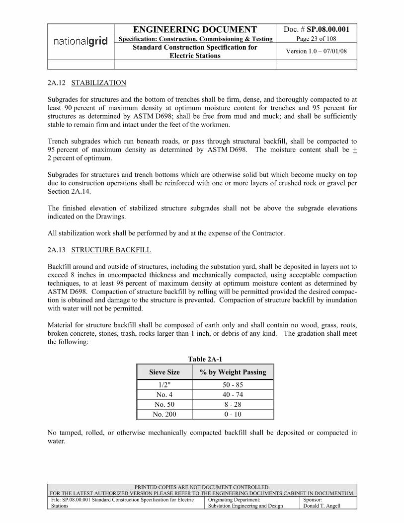
ENGINEERING DOCUMENT Doc. # SP.08.00.001Specification: Construction, Commissioning & Testing Page 23 of 108
Standard Construction Specification for Electric Stations Version 1.0 – 07/01/08
PRINTED COPIES ARE NOT DOCUMENT CONTROLLED. FOR THE LATEST AUTHORIZED VERSION PLEASE REFER TO THE ENGINEERING DOCUMENTS CABINET IN DOCUMENTUM.File: SP.08.00.001 Standard Construction Specification for Electric Stations
Originating Department:Substation Engineering and Design
Sponsor:Donald T. Angell
2A.12 STABILIZATION
Subgrades for structures and the bottom of trenches shall be firm, dense, and thoroughly compacted to at least 90 percent of maximum density at optimum moisture content for trenches and 95 percent for structures as determined by ASTM D698; shall be free from mud and muck; and shall be sufficiently stable to remain firm and intact under the feet of the workmen.
Trench subgrades which run beneath roads, or pass through structural backfill, shall be compacted to 95 percent of maximum density as determined by ASTM D698. The moisture content shall be +2 percent of optimum.
Subgrades for structures and trench bottoms which are otherwise solid but which become mucky on top due to construction operations shall be reinforced with one or more layers of crushed rock or gravel per Section 2A.14.
The finished elevation of stabilized structure subgrades shall not be above the subgrade elevations indicated on the Drawings.
All stabilization work shall be performed by and at the expense of the Contractor.
2A.13 STRUCTURE BACKFILL
Backfill around and outside of structures, including the substation yard, shall be deposited in layers not to exceed 8 inches in uncompacted thickness and mechanically compacted, using acceptable compaction techniques, to at least 98 percent of maximum density at optimum moisture content as determined by ASTM D698. Compaction of structure backfill by rolling will be permitted provided the desired compac-tion is obtained and damage to the structure is prevented. Compaction of structure backfill by inundation with water will not be permitted.
Material for structure backfill shall be composed of earth only and shall contain no wood, grass, roots,broken concrete, stones, trash, rocks larger than 1 inch, or debris of any kind. The gradation shall meet the following:
Table 2A-1
Sieve Size % by Weight Passing
1/2" 50 - 85No. 4 40 - 74No. 50 8 - 28
No. 200 0 - 10
No tamped, rolled, or otherwise mechanically compacted backfill shall be deposited or compacted in water.
ENGINEERING DOCUMENT Doc. # SP.08.00.001Specification: Construction, Commissioning & Testing Page 24 of 108
Standard Construction Specification for Electric Stations Version 1.0 – 07/01/08
PRINTED COPIES ARE NOT DOCUMENT CONTROLLED. FOR THE LATEST AUTHORIZED VERSION PLEASE REFER TO THE ENGINEERING DOCUMENTS CABINET IN DOCUMENTUM.File: SP.08.00.001 Standard Construction Specification for Electric Stations
Originating Department:Substation Engineering and Design
Sponsor:Donald T. Angell
2A.13 STRUCTURE BACKFILL (continued)
All backfill material shall consist of loose earth having moisture content such that the required density of the compacted soil will be obtained with the compaction method used. Moisture content shall be distributed uniformly and water for correction of moisture content shall be added sufficiently in advance so proper moisture distribution and compaction will be obtained.
Particular care shall be taken to compact structure backfill which will be beneath precast trenches, conduits, drives, roads, or other surface construction or structures.
2A.14 COMPACTED SAND FILL
Compacted sand fill material shall consist of clean natural sand. The sand shall conform to ASTM C33 and not less than 75 percent shall pass a No. 4 sieve. Not more than 10 percent shall pass a No. 200 sieve.
Inundated sand fills shall be placed on a suitable subgrade and shall be placed with suitable arrangements for retention of water until compaction is completed and water is disposed of after compaction. The sand shall be deposited in, or simultaneously with the application of, clean water so that the sand is kept inundated at all times. During placement and inundation, the sand shall be compacted to 70 percent relative density as determined by ASTM D4253 and D4254 using mechanical probe type vibrators.
Tamped sand fills shall be placed on a suitable subgrade. The sand shall be wet, not just damp, when placed and moisture content shall be adjusted for maximum density. Compaction shall be performed with vibrating platform type compactors.
If concrete is to be placed on the compacted sand fill, a polyethylene film moisture barrier shall be placed over the sand as specified in the section titled CAST-IN-PLACE CONCRETE.
2A.15 TRANSFORMER DRAINAGE FILL
Transformer drainage fill shall be uniformly graded washed crushed stone of 3 inch size. Unwashed drainage material is unacceptable. A minimum void ratio of 40 percent is required.
Drainage material shall be placed to the approximate limits indicated on the Drawings, and shall be lightly compacted to minimize settlement without sacrificing permeability.

ENGINEERING DOCUMENT Doc. # SP.08.00.001Specification: Construction, Commissioning & Testing Page 25 of 108
Standard Construction Specification for Electric Stations Version 1.0 – 07/01/08
PRINTED COPIES ARE NOT DOCUMENT CONTROLLED. FOR THE LATEST AUTHORIZED VERSION PLEASE REFER TO THE ENGINEERING DOCUMENTS CABINET IN DOCUMENTUM.File: SP.08.00.001 Standard Construction Specification for Electric Stations
Originating Department:Substation Engineering and Design
Sponsor:Donald T. Angell
2A.16 TRANSFORMER OIL SUMP SYSTEM
The transformer oil sump system shall be in accordance with the following.
2A.16.1 Geotextile Fabric. Geotextile fabric shall be a non woven fabric consisting of continuous chain polymeric filaments or yarns of polyester, or polypropylene formed into a stable network by needle punching.
The geotextile fabric shall be inert to commonly encountered chemicals and hydrocarbons. It shall be resistant to mildew and rot, ultraviolet radiation, insects, and rodents. The geotextile shall conform to the properties in table 2A-2. The average roll minimum value for strength properties shall be in excess of the average roll minimum value stipulated below. The average roll minimum value is defined as the sampling average, in the weakest principal direction, of the designated physical properties for the roll within a production lot designated first quality.
Table 2A-2
Physical Properties Average RollMinimum Value
Grab tensile strength (lb) ASTM D4632-86 200
Elongation at failure (percent) ASTM D4632-86 50
Thickness (mils) ASTM D1777-64 (1975) 90
Puncture strength (lb) ASTM D4833-88 80
Weight (oz/yd2) ASTM D3776-85 16
The geotextile shall be 16 oz./yard2 polypropylene fabric, Philips ASUPAC@ 16 NP or Owner approved equal.
The geotextile shall be furnished in rolls wrapped with a covering to protect the fabric from mud, dirt, dust, and debris. The fabric shall be free of defects or flaws that affect its physical properties. Each roll of fabric shall be labeled to identify its production run.
a. Inspection and Testing. The following tests and documentation shall be submitted to the Owner for review before beginning liner installation.
ENGINEERING DOCUMENT Doc. # SP.08.00.001Specification: Construction, Commissioning & Testing Page 26 of 108
Standard Construction Specification for Electric Stations Version 1.0 – 07/01/08
PRINTED COPIES ARE NOT DOCUMENT CONTROLLED. FOR THE LATEST AUTHORIZED VERSION PLEASE REFER TO THE ENGINEERING DOCUMENTS CABINET IN DOCUMENTUM.File: SP.08.00.001 Standard Construction Specification for Electric Stations
Originating Department:Substation Engineering and Design
Sponsor:Donald T. Angell
b. Quality Control. A competent laboratory shall be retained at the point of manufacture to provide quality control in accordance with the specified ASTM testing procedures and ASTM D4759-88. Records of the quality control tests shall be provided to the Owner, in the form of a manufacturer's certificate that includes the following:
• Name of manufacturer• Chemical composition• Product description• Physical Properties• Statement of compliance with specification requirements• Signature of legally authorized official attesting to the information required
c. The geotextile shall be tested and certified to be in accordance with this Specification by an independent laboratory. This data, along with a sample of the material, shall be submitted to the Owner.
d. Installation. Two layers of geotextile shall be installed in accordance with the manufacturer's recommendations, as indicated on the Drawings included in theSubstation Field Issue and as specified.
Installation work shall not begin until all required data have been submitted and the acceptability of the subgrade reviewed by the Owner.
The bottom layer of geotextile shall be installed, in accordance with the manufacturer's requirements, on the prepared subgrade. All seams shall overlap 12 inches minimum.
A 12 inch layer of fill material consisting of 1" minus processed gravel compacted to 92% dry density as determined by ASTM D698 shall be installed on the bottom layer of geotextile.
The second layer of fabric shall be installed, in accordance with the manufacturer's requirements, on the processed gravel fill to the limits indicated on the Drawings. All seams shall overlap 12 inches minimum.
2A.16.2 Oil Sump Clean Out. To facilitate oil removal from the sump in the event a transformer leak occurs, a 6 inch perforated schedule 40 PVC drain pipe shall be installed vertically in each of the four corners of the sump. The pipes shall have 1 inch diameter holes placed in rows (4 per row at the quarter points) spaced 3 inches apart to within 6 inches of the top of the pipe. Holes in adjacent rows shall be staggered. The pipes shall extend from top layer of the geotextile to finished grade level and capped with a threaded plug to keep out debris. Care must be taken to insure that no overhanging part of the transformer will block insertion of the suction hose.
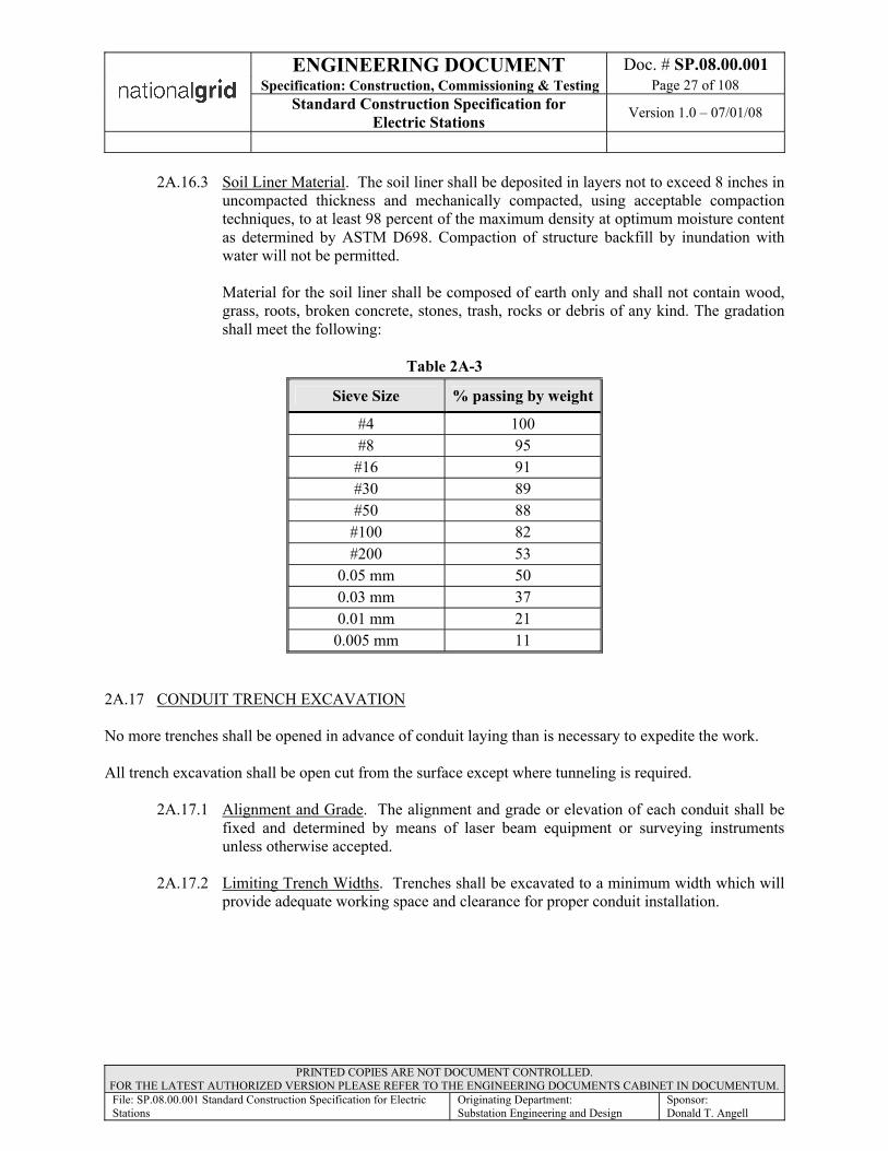
ENGINEERING DOCUMENT Doc. # SP.08.00.001Specification: Construction, Commissioning & Testing Page 27 of 108
Standard Construction Specification for Electric Stations Version 1.0 – 07/01/08
PRINTED COPIES ARE NOT DOCUMENT CONTROLLED. FOR THE LATEST AUTHORIZED VERSION PLEASE REFER TO THE ENGINEERING DOCUMENTS CABINET IN DOCUMENTUM.File: SP.08.00.001 Standard Construction Specification for Electric Stations
Originating Department:Substation Engineering and Design
Sponsor:Donald T. Angell
2A.16.3 Soil Liner Material. The soil liner shall be deposited in layers not to exceed 8 inches in uncompacted thickness and mechanically compacted, using acceptable compaction techniques, to at least 98 percent of the maximum density at optimum moisture content as determined by ASTM D698. Compaction of structure backfill by inundation with water will not be permitted.
Material for the soil liner shall be composed of earth only and shall not contain wood, grass, roots, broken concrete, stones, trash, rocks or debris of any kind. The gradation shall meet the following:
Table 2A-3
Sieve Size % passing by weight
#4 100#8 95#16 91#30 89#50 88#100 82#200 53
0.05 mm 500.03 mm 370.01 mm 21
0.005 mm 11
2A.17 CONDUIT TRENCH EXCAVATION
No more trenches shall be opened in advance of conduit laying than is necessary to expedite the work.
All trench excavation shall be open cut from the surface except where tunneling is required.
2A.17.1 Alignment and Grade. The alignment and grade or elevation of each conduit shall be fixed and determined by means of laser beam equipment or surveying instruments unless otherwise accepted.
2A.17.2 Limiting Trench Widths. Trenches shall be excavated to a minimum width which will provide adequate working space and clearance for proper conduit installation.

ENGINEERING DOCUMENT Doc. # SP.08.00.001Specification: Construction, Commissioning & Testing Page 28 of 108
Standard Construction Specification for Electric Stations Version 1.0 – 07/01/08
PRINTED COPIES ARE NOT DOCUMENT CONTROLLED. FOR THE LATEST AUTHORIZED VERSION PLEASE REFER TO THE ENGINEERING DOCUMENTS CABINET IN DOCUMENTUM.File: SP.08.00.001 Standard Construction Specification for Electric Stations
Originating Department:Substation Engineering and Design
Sponsor:Donald T. Angell
2A.18 TRENCH BACKFILL
All trench backfill above conduit encasement shall conform to the following requirements.
2A.18.1 Compacted Backfill. Compacted backfill will be required for the full depth of the trench above the embedment.
a. Compacted backfill material shall meet the requirements specified hereinafter. Compacted backfill material shall be either suitable job excavated material or suitable material furnished by the Contractor from his own sources.
b. Compacted backfill material shall be finely divided and free from debris, organic material, and stones larger than 4 inches in greatest dimension. Compacted backfill material shall be placed in uniform layers not exceeding 8 inches in non compacted thickness. The method of compaction and the equipment used shall be appropriate for the material to be compacted and shall not transmit damaging shocks to the conduit. Trench backfill shall be compacted to not less than 95 percent of maximum density.
c. Backfill for trenches traversing subgrades of roads, parking areas, underground electrical ducts and conduit, and other facilities subject to damage by settlement shall be compacted to not less than 95 percent of maximum density. Moisture content of backfill material shall be adjusted as required to obtain the specified density with the compaction equipment used.
d. Backfill material shall be compacted to the densities specified hereinbefore as determined by ASTM D698.
2A.19 MAINTENANCE & RESTORATION OF FILLS, EMBANKMENTS, & BACKFILLS
Fills, embankments, and backfills that settle or erode before Final Acceptance of the work, and pavement, structures, trenches, and other facilities damaged by such settlement or erosion, shall be repaired. The settled or eroded areas shall be refilled, compacted, and graded to conform to the elevation indicated on the Drawings or to the elevation of the adjacent ground surface. Damaged facilities shall be repaired in a manner acceptable to the Owner.
Earth slopes of the roads constructed under this Specification shall be maintained to the lines and grades indicated on the Drawings until the final acceptance of the road slopes by the authorities having jurisdic-tion.
ENGINEERING DOCUMENT Doc. # SP.08.00.001Specification: Construction, Commissioning & Testing Page 29 of 108
Standard Construction Specification for Electric Stations Version 1.0 – 07/01/08
PRINTED COPIES ARE NOT DOCUMENT CONTROLLED. FOR THE LATEST AUTHORIZED VERSION PLEASE REFER TO THE ENGINEERING DOCUMENTS CABINET IN DOCUMENTUM.File: SP.08.00.001 Standard Construction Specification for Electric Stations
Originating Department:Substation Engineering and Design
Sponsor:Donald T. Angell
2A.20 FINAL GRADING
After all construction work has been completed, all ground surface areas disturbed by this construction shall be graded. The grading shall be finished to the contours and elevations indicated on the Drawings or, if not indicated, to the matching contours and elevations of the original, undisturbed ground surface. The final grading shall provide smooth uniform surfacing and effective drainage of the ground areas.
2A.21 DISPOSITION OF MATERIALS
Excavated earth material shall be used to construct fills, embankments, and backfills to the extent required. Surplus earth, if any, and materials which are not suitable for fills, embankments, and backfills shall be removed from the site by and at the expense of the Contractor. This work shall be done in accordance with the Owner’s Environmental Protection Policy and in a manner acceptable to the Owner.
If additional material is required, it shall conform to Section 2A.13
Section 2B (033000) - CAST IN-PLACE CONCRETE
2B.1 GENERAL
This section covers all cast-in-place concrete and includes reinforcing steel, forms, finishing, curing, and other appurtenant work.
Cast-in-place concrete shall be in accordance with the latest applicable requirements of Specifications, ACI, ASTM, and CRSI, except as modified by this Specification.
The Contractor shall inform the Owner at least 24 hours in advance of the times and places at which it intends to place concrete.
ENGINEERING DOCUMENT Doc. # SP.08.00.001Specification: Construction, Commissioning & Testing Page 30 of 108
Standard Construction Specification for Electric Stations Version 1.0 – 07/01/08
PRINTED COPIES ARE NOT DOCUMENT CONTROLLED. FOR THE LATEST AUTHORIZED VERSION PLEASE REFER TO THE ENGINEERING DOCUMENTS CABINET IN DOCUMENTUM.File: SP.08.00.001 Standard Construction Specification for Electric Stations
Originating Department:Substation Engineering and Design
Sponsor:Donald T. Angell
2B.2 MATERIALS
Materials shall be in accordance with the following requirements: Table 2B-1
Material RequirementCement ASTM C150, Type II.Fine aggregate Clean natural sand, ASTM C33.Coarse aggregate Crushed stone or worked gravel conforming to ASTM C33, Size 467
or 57, Class 3SWater Clean and free from mud, oil, organic matter, or other deleterious
substancesAdmixturesPlasticizer ASTM C494, Type A; Grace "WRDA17," Master Builders "Pozzolith
300N," Sika Chemical "Plastocrete 161," or acceptable equalAir-entraining agent ASTM C260; Grace "Darex AEA," Master Builders "Micro-Air," Sika
Chemical "AER," or acceptable equalPlasticizing retarder ASTM C494, Type D; Grace "Daratard17," Master Builders
"Pozzolith 300R," Sika Chemical "Plastocrete 161R," or acceptable equal
Reinforcing steel bars ASTM A615-90 Grade 60. Yield strength shall be determined by full size bar tests.
Welded wire fabric ASTM A185 or A497.Water StopsFlexible PVC ribbed or serrated, 9 inches by 3/8 inch, with AO@ bulb closed
center sections unless otherwise indicated on the Drawings. Grace ADurajoint Type 7", W.R. Meadows ASealtight Type 9380", or Vinylex ARB9-38"
FormsForm coating Nox-Crete "Nox-Crete FormCoating," L & M "Debond," Protex "Pro-
Cote," or Richmond ARich Cote.”Polyethylene film Fed Spec L-P-378, Type I; 6 mil.Expansion Joint Materials Filler Preformed, ASTM D1752, Type I (sponge rubber) or closed
cellplastic foam (PVC or polyethylene)Urethane sealant Two component, Fed Spec TT-S- (self-leveling) 00227, Type 1, Class
A; Pecora "NR-200 Urexpan" or Tremco"TCH-900," gray colorPrimer As recommended by sealant manufacturerEpoxy bonding compound Sika Chemical "Sikadur Hi-Mod," U.S. Grout "Five Star Epoxy," or
acceptable equalMembrane Curing Compound Styrene-acrylate or styrene-butadiene; minimum and 18 percent solids,
non-yellowing, unit moisture floor sealer loss 0.039 g/sq cm maximum, Gifford-Hill "Sealco800," ProSoCo "Kure and Seal,"Protex "Acryseal," Sonneborn "Kure-N-Seal," or L&M "Dress & Seal."
ENGINEERING DOCUMENT Doc. # SP.08.00.001Specification: Construction, Commissioning & Testing Page 31 of 108
Standard Construction Specification for Electric Stations Version 1.0 – 07/01/08
PRINTED COPIES ARE NOT DOCUMENT CONTROLLED. FOR THE LATEST AUTHORIZED VERSION PLEASE REFER TO THE ENGINEERING DOCUMENTS CABINET IN DOCUMENTUM.File: SP.08.00.001 Standard Construction Specification for Electric Stations
Originating Department:Substation Engineering and Design
Sponsor:Donald T. Angell
2B.3 PRELIMINARY REVIEW
The source and quality of concrete materials and the concrete proportions proposed for the work shall be submitted to the Owner for review before the concrete work is started. Complete certified reports covering the materials and proportions shall be prepared by an independent testing laboratory and submitted to the Owner for each concrete class.
2B.4 LIMITING REQUIREMENTS
These requirements shall apply to concrete containing either the specified plasticizer or plasticizing retarder. A plasticizer or plasticizing retarder shall be included in all concrete mixes.
Table 2B-2Minimum cement content for each course
aggregate size range1-1/2 inch to No. 4
sieve 585 lb/cu yd
3/4 inch to No. 4 sieve 600 lb/cu yd
Maximum water/cement ratio 0.45
Coarse aggregate size Refer to Table 2B-3
Consistency
Workable, without segregation, with
slump not more than 2 inches 1 inch when concrete is placed
.
Table 2B-3 Concrete Mixes
MixNumber
Strength Minimum
28 DayLbs/Square Inch
Aggregate Max. Size Nominal
Slump Not More Than
Air-Entraining
Content Typical Uses
M1 2,000 1/2" 6" ------- Duct Lines -Unit Method
M2 4,000 1" 2" 6.0%+/- 1.0%
Piers, Slabs and Walls
ENGINEERING DOCUMENT Doc. # SP.08.00.001Specification: Construction, Commissioning & Testing Page 32 of 108
Standard Construction Specification for Electric Stations Version 1.0 – 07/01/08
PRINTED COPIES ARE NOT DOCUMENT CONTROLLED. FOR THE LATEST AUTHORIZED VERSION PLEASE REFER TO THE ENGINEERING DOCUMENTS CABINET IN DOCUMENTUM.File: SP.08.00.001 Standard Construction Specification for Electric Stations
Originating Department:Substation Engineering and Design
Sponsor:Donald T. Angell
2B.5 STORAGE OF MATERIALS
Reinforcing steel shall be carefully handled and shall be stored on supports which will keep the steel from contact with the ground.
2B.6 BATCHING AND MIXING
Batching and mixing shall be performed by an acceptable ready-mix concrete supplier. Personnel at the batching and mixing plant shall be qualified and experienced.
2B.6.1 Batching. The measurement of aggregates and cement shall be by weight. Aggregate weights shall be adjusted for the moisture content.
Each admixture shall be dispensed by a mechanical device that will ensure accurate and automatic measurement.
The minimum amount of water required to produce the desired slump shall be batched automatically. Slump shall be kept uniform. Aggregates shall float uniformly throughout the mass and the concrete shall flow sluggishly when vibrated.
2B.6.2 Mixing. Concrete shall be mixed until all ingredients are uniformly distributed throughout the batch. Mixers shall not be loaded in excess of their rated capacities. Each batch shall be completely discharged before the mixer is recharged.
2B.6.3 Ready-Mixed Concrete. Ready-mixed concrete shall conform to ASTM C94, except as otherwise specified herein.
A delivery ticket shall be prepared for each load of ready-mixed concrete delivered. A copy of each ticket shall be handed to the Owner by the truck operator at the time of delivery. Tickets shall indicate the mix identification, the number of yards delivered, the quantities of each material in the batch, the outdoor temperature in the shade, the time at which the cement was added, and the numerical sequence of the delivery.
When a truck mixer or agitator is used for transporting concrete, the concrete shall be delivered to the site of the work and discharge shall be completed within 1-1/2 hours, or before the drum has been revolved 300 revolutions, whichever comes first, after the introduction of the mixing water to the cement and aggregates, or the introduction of the cement to the aggregates, unless a longer time is specifically accepted by the Owner. In hot weather, or under conditions contributing to quick stiffening of the concrete, a time less than 1-1/2 hours may be required by the Owner. When a truck mixer is used for the complete mixing of the concrete, the mixing operation shall begin within 30 minutes after the cement has been intermingled with the aggregates. Truck mixers shall be revolving drum type and shall be equipped with a mixing water tank. Only the prescribed amount of mixing water shall be placed in the tank for any one batch, unless the tank is equipped with a device by which the amount of water added to each batch can be readily verified by the Owner.

ENGINEERING DOCUMENT Doc. # SP.08.00.001Specification: Construction, Commissioning & Testing Page 33 of 108
Standard Construction Specification for Electric Stations Version 1.0 – 07/01/08
PRINTED COPIES ARE NOT DOCUMENT CONTROLLED. FOR THE LATEST AUTHORIZED VERSION PLEASE REFER TO THE ENGINEERING DOCUMENTS CABINET IN DOCUMENTUM.File: SP.08.00.001 Standard Construction Specification for Electric Stations
Originating Department:Substation Engineering and Design
Sponsor:Donald T. Angell
2B.7 FIELD CONTROL TESTING
Field control tests, consisting of aggregate gradation tests, slump tests, air content tests, and the securing of compression test cylinders, shall be made by an independent testing laboratory. The independent testing laboratory shall provide all equipment and supplies and the services of one or more employees as necessary for the field control testing.
All tests required for preliminary review, field quality control and compression tests for the entire project shall be tested by an acceptable independent testing laboratory at the expense of the Contractor.
The frequency hereinafter specified for each field control test is a minimum. If additional field control tests are necessary, in the opinion of the Owner, such tests shall be made.
2B.7.1 Aggregate Gradation. It is not anticipated that aggregate gradation tests will be required after the tests made for the initial acceptance of the materials. However, if directed to do so by the Owner, the Contractor shall sample and test the fine and coarse aggregate in accordance with ASTM D75 and C136.
2B.7.2 Slump. A slump test shall be made from each of the first three batches mixed each day. An additional slump test shall be made for each additional 25 cubic yards of concrete placed in any one day. Slump shall be determined in accordance with ASTM C143.
Each set of compression test cylinders shall be marked or tagged with the slump.
2B.7.3 Air Content. An air content test shall be made from one of the first three batches mixed each day and from each batch of concrete from which concrete compression test cylinders are made. Air content shall be determined in accordance with ASTM C231.
Each set of compression test cylinders shall be marked or tagged with the air content.
2B.7.4 Compression Tests. A set of three compression test cylinders shall be made each day concrete is placed. An additional set of three compression test cylinders shall be made for each additional 25 cubic yards of concrete placed in 1 day. One cylinder of each set shall be tested at an age of 7 days and the other cylinder of each set shall be tested at an age of 28 days. The third cylinder will be kept as a spare for additional testing, if required.
Concrete test cylinders shall be made, cured, stored, and delivered to the laboratory in accordance with ASTM C31 and tested in accordance with ASTM C39.
Each set of compression test cylinders shall be marked or tagged with the date and time of day the cylinders were made, the location in the work where the concrete represented by the cylinders was placed, the delivery truck or batch number, the air content, and the slump.
2B.7.5 Test Reports. The Contractor shall promptly furnish the Owner, and all other persons designated by the Owner, certified reports of all tests made by the testing laboratory.
ENGINEERING DOCUMENT Doc. # SP.08.00.001Specification: Construction, Commissioning & Testing Page 34 of 108
Standard Construction Specification for Electric Stations Version 1.0 – 07/01/08
PRINTED COPIES ARE NOT DOCUMENT CONTROLLED. FOR THE LATEST AUTHORIZED VERSION PLEASE REFER TO THE ENGINEERING DOCUMENTS CABINET IN DOCUMENTUM.File: SP.08.00.001 Standard Construction Specification for Electric Stations
Originating Department:Substation Engineering and Design
Sponsor:Donald T. Angell
2B.8 REINFORCEMENTS
Reinforcements shall be accurately formed. Unless otherwise indicated on the Drawings or specified herein, the details of fabrication shall conform to ACI 318-95.
2B.8.1 Accessories. The Contractor shall provide all bar supports, ties, spacers, bolsters,inserts, screeds, and other concrete accessories required to maintain reinforcing in its proper position and permit proper placement of concrete.
The Contractor shall be responsible for the design of all bar support systems.
2B.8.2 Certification. The Contractor shall furnish the Owner with a certification that the reinforcing steel furnished complies with the requirements specified in the article titled MATERIALS. The certification shall be signed by the Contractor and the reinforcing steel fabricator.
2B.8.3 Welding. Except where indicated on the Drawings, welding of reinforcement for any purpose, and tack welding in particular, is expressly prohibited. Reinforcements upon which unauthorized welding has been done shall be presumed to be damaged and such reinforcing shall be removed and replaced at the Contractor's expense. Replacement materials shall conform to all applicable requirements of this Specification.
Welded chairs and supports may be used provided they are clamped or wired to the reinforcement.
2B.8.4 Concrete Cover. Except as otherwise indicated on the Drawings, metal reinforcement for concrete shall have a minimum concrete protective cover of 3 inches.
2B.8.5 Placement. Reinforcements shall be accurately positioned on supports, spacers, hangers, or other reinforcements, and shall be secured in place with wire ties or suitable clips. Bare metal supports shall not be used in contact with forms for exposed surfaces.
2B.8.6 Splices. Unless otherwise required by this Specification or Drawings, splices shall conform to ACI 318-95. Splices in horizontal reinforcement placed in vertical wall sections shall be detailed in accordance with the top reinforcement requirements of ACI 318-95.
Splices shall not be used in regions of maximum bending stress. Welded splices shall not be used.
2B.9 FORMS
Forms shall be designed to produce hardened concrete having the shape, lines, and dimensions indicated on the Drawings. Forms shall be constructed and maintained in proper position and accurate alignment. Forms shall conform to ACI 347.

ENGINEERING DOCUMENT Doc. # SP.08.00.001Specification: Construction, Commissioning & Testing Page 35 of 108
Standard Construction Specification for Electric Stations Version 1.0 – 07/01/08
PRINTED COPIES ARE NOT DOCUMENT CONTROLLED. FOR THE LATEST AUTHORIZED VERSION PLEASE REFER TO THE ENGINEERING DOCUMENTS CABINET IN DOCUMENTUM.File: SP.08.00.001 Standard Construction Specification for Electric Stations
Originating Department:Substation Engineering and Design
Sponsor:Donald T. Angell
2B.9.1 Design. Forms shall be substantial and sufficiently tight to prevent leakage of mortar. They shall be properly braced or tied so that they will maintain the desired position, shape, and alignment during and after placing concrete therein.
2B.9.2 Form Ties. Form ties shall be of the removable end, permanently embedded body type, and shall have sufficient strength, stiffness, and rigidity to support and maintain the form in proper position and alignment without the use of auxiliary spreaders. Outer ends of the permanently embedded portions of form ties shall be at least 1 inch back from adjacent outer concrete faces. Permanently embedded portions of form ties which are not provided with threaded ends shall be constructed so that the removable ends can be broken off by twisting, without chipping or spalling the concrete surface. The type of form ties used shall be acceptable to the Owner.
Form ties in exposed surfaces shall be uniformly spaced and aligned in horizontal and vertical rows.
2B.9.3 Edges and Corners. Chamfer strips shall be placed in forms to bevel all salient edges and corners except edges which are to be buried and edges which are indicated on the drawings with a special treatment. Equipment bases shall have formed beveled salient edges for all vertical and horizontal corners unless specifically indicated otherwise on the drawings. Bevel dimensions shall be 3/4 by 3/4 inch unless indicated otherwise on the Drawings.
2B.9.4 Form Removal. Forms shall not be removed or disturbed until the concrete has attained sufficient strength to safely support all dead and live loads to be imposed thereon. Supports beneath beams or slabs shall be left in place and reinforced as necessary to carry any construction equipment or materials placed thereon. Care shall be taken in form removal to avoid surface gouging, corner or edge breakage, or other damage to the concrete.
2B.10 EMBEDMENTS
Anchor bolts, castings, steel shapes, conduit, sleeves, masonry anchorages, and other materials that are to be embedded in the concrete shall be accurately positioned and securely anchored.
Anchor bolts shall be provided with sufficient threads to permit a nut to be installed on the concrete side of the form or template. A second nut shall be installed on the other side of the form or template and the two nuts shall be adjusted so the bolt will be held rigidly in proper position.
Embedments shall not be welded to reinforcement.
Embedments shall be clean when they are installed. After concrete placement, surfaces not in contact with concrete shall be cleaned of all concrete spatter and other foreign substances.

ENGINEERING DOCUMENT Doc. # SP.08.00.001Specification: Construction, Commissioning & Testing Page 36 of 108
Standard Construction Specification for Electric Stations Version 1.0 – 07/01/08
PRINTED COPIES ARE NOT DOCUMENT CONTROLLED. FOR THE LATEST AUTHORIZED VERSION PLEASE REFER TO THE ENGINEERING DOCUMENTS CABINET IN DOCUMENTUM.File: SP.08.00.001 Standard Construction Specification for Electric Stations
Originating Department:Substation Engineering and Design
Sponsor:Donald T. Angell
2B.11 PLACEMENT
The handling, depositing, and compacting of concrete shall conform to this Specification subject to adjustment by the Owner for weather or placement conditions.
Concrete shall not be pumped through aluminum pipe or aluminum alloy pipe.
Concrete placement shall be coordinated such that construction joints are not required.
Before concrete is placed, forms, reinforcements, water stops, anchor bolts, and embedments shall be rigidly secured in proper position; all dirt, mud, water, and debris shall be removed from the space to be occupied by the concrete; all surfaces which may have become encrusted with dried mortar or concrete from previous placement operations shall be cleaned; and the entire installation shall be acceptable to the Owner.
2B.11.1 Bonding to Hardened Concrete. The surface of hardened concrete against which fresh concrete is to be placed shall be rough, clean, and damp. Surface mortar shall be removed to expose the aggregate. The hardened surface shall be cleaned of all foreign substances (including curing compound), washed with clean water, and kept saturated during the 24 hour period preceding placement of fresh concrete.
2B.11.2 Conveyance and Distribution. Concrete shall be conveyed to the point of final deposit by methods which will prevent the separation or loss of the ingredients. Concrete shall be deposited in its final position without moving it laterally in the forms for a distance in excess of 5 feet.
2B.11.3 Depositing Concrete. Horizontal and vertical construction joints shall be provided as necessary and as accepted by the Owner to comply with these requirements.
Plastic concrete is defined as concrete which can be re-vibrated at least to the extent that an immersion type vibrator spud will penetrate the concrete at least 1 inch by vibration action and its own weight. Concrete shall remain plastic to this extent for at least 2-1/2 hours after initial contact of cement and water. Concrete which is no longer plastic but which must be covered by an additional lift shall be immediately chipped back to well consolidated concrete, slushed with mortar puddle as specified in the article titled Bonding to Hardened Concrete, and otherwise treated as accepted by the Owner to ensure that a cold joint will not occur. If the pour requirements do not exceed the Contractor's placing ability, these measures should not be necessary.
Concrete shall be thoroughly settled when top finished. All laitance, debris, and surplus water shall be removed from concrete surfaces at top of forms by screeding, scraping, or other effective means. Wherever the top of a wall will be exposed to weathering, the forms shall be overfilled and after the concrete has settled the excess shall be screeded off.
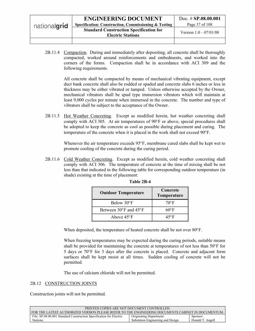
ENGINEERING DOCUMENT Doc. # SP.08.00.001Specification: Construction, Commissioning & Testing Page 37 of 108
Standard Construction Specification for Electric Stations Version 1.0 – 07/01/08
PRINTED COPIES ARE NOT DOCUMENT CONTROLLED. FOR THE LATEST AUTHORIZED VERSION PLEASE REFER TO THE ENGINEERING DOCUMENTS CABINET IN DOCUMENTUM.File: SP.08.00.001 Standard Construction Specification for Electric Stations
Originating Department:Substation Engineering and Design
Sponsor:Donald T. Angell
2B.11.4 Compaction. During and immediately after depositing, all concrete shall be thoroughly compacted, worked around reinforcements and embedments, and worked into the corners of the forms. Compaction shall be in accordance with ACI 309 and the following requirements.
All concrete shall be compacted by means of mechanical vibrating equipment, except duct bank concrete shall also be rodded or spaded and concrete slabs 6 inches or less in thickness may be either vibrated or tamped. Unless otherwise accepted by the Owner, mechanical vibrators shall be spud type immersion vibrators which will maintain at least 9,000 cycles per minute when immersed in the concrete. The number and type of vibrators shall be subject to the acceptance of the Owner.
2B.11.5 Hot Weather Concreting. Except as modified herein, hot weather concreting shall comply with ACI 305. At air temperatures of 90°F or above, special procedures shall be adopted to keep the concrete as cool as possible during placement and curing. The temperature of the concrete when it is placed in the work shall not exceed 90°F.
Whenever the air temperature exceeds 95°F, membrane cured slabs shall be kept wet to promote cooling of the concrete during the curing period.
2B.11.6 Cold Weather Concreting. Except as modified herein, cold weather concreting shall comply with ACI 306. The temperature of concrete at the time of mixing shall be not less than that indicated in the following table for corresponding outdoor temperature (in shade) existing at the time of placement:
Table 2B-4
Outdoor Temperature Concrete Temperature
Below 30°F 70°FBetween 30°F and 45°F 60°F
Above 45°F 45°F
When deposited, the temperature of heated concrete shall be not over 80°F.
When freezing temperatures may be expected during the curing periods, suitable means shall be provided for maintaining the concrete at temperatures of not less than 50°F for 5 days or 70°F for 3 days after the concrete is placed. Concrete and adjacent form surfaces shall be kept moist at all times. Sudden cooling of concrete will not be permitted.
The use of calcium chloride will not be permitted.
2B.12 CONSTRUCTION JOINTS
Construction joints will not be permitted.
ENGINEERING DOCUMENT Doc. # SP.08.00.001Specification: Construction, Commissioning & Testing Page 38 of 108
Standard Construction Specification for Electric Stations Version 1.0 – 07/01/08
PRINTED COPIES ARE NOT DOCUMENT CONTROLLED. FOR THE LATEST AUTHORIZED VERSION PLEASE REFER TO THE ENGINEERING DOCUMENTS CABINET IN DOCUMENTUM.File: SP.08.00.001 Standard Construction Specification for Electric Stations
Originating Department:Substation Engineering and Design
Sponsor:Donald T. Angell
2B.13 FINISHING FORMED SURFACES
All fins and other surface projections shall be removed from all formed surfaces from which the forms are stripped except exterior surfaces that will be in contact with earth backfill. In addition, exterior surfaces which will be exposed above grade and all interior surfaces, except interior surfaces which are not usually exposed to view, shall be cleaned and rubbed. Rubbing shall produce a smooth, uniform surface free of marks, voids, surface glaze, and discolorations.
Rubbing shall be done by hand with a carborundum stone using only the mortar produced by the rubbing action and the application of water.
Projecting ends of all form ties shall be removed and the resulting recesses shall be cleaned, wetted, and filled with patching mortar. For rubbed surfaces, patches shall match the texture of the adjacent concrete. Rubbing shall be performed within 24 hours of removing forms.
2B.14 FINISHING UNFORMED SURFACES
No surface treatment will be required for buried or permanently submerged concrete not forming an integral part of a structure except that required to obtain the surface elevations or contours and surfaces free of laitance. The unformed surfaces of all other concrete shall be screeded and given an initial float finish followed by additional floating and troweling where required.
Float finished surfaces shall be finished to provide a flat profile within 1/4 inch deviation as measured from a 10 foot straightedge. Trowel finished surfaces shall be finished to form a flat plane in which the profile shall not deviate more than 1/8 inch when measured from a 10 foot straightedge.
2B.14.1 Screeding. Screeding shall provide a concrete surface conforming to the proper elevation and contour with all aggregates completely embedded in adjacent mortar. Surface irregularities in screeded surfaces shall be limited as required to produce finished surfaces within the tolerances specified. If no further finishing is required, surface irregularities shall not exceed 1/4 inch as measured from a 10 foot straightedge.
2B.14.2 Floating. Screeded surfaces shall be given an initial float finish as soon as the concrete has stiffened sufficiently for proper working. Any piece of coarse aggregate which may be disturbed by the float or which causes a surface irregularity shall be removed and replaced with mortar. Initial floating shall produce a surface of uniform texture and appearance with no unnecessary working of the surface with the float.
Initial floating shall be followed by a second floating at the time of initial set. The second floating shall produce a smooth, uniform, and workmanlike float finish of uniform texture and color. Unless additional finishing is specifically required, the completed finish for all unformed surfaces shall be a float finish as produced by the second floating.
Floating shall be performed with hand floats or suitable mechanical compactor floats.

ENGINEERING DOCUMENT Doc. # SP.08.00.001Specification: Construction, Commissioning & Testing Page 39 of 108
Standard Construction Specification for Electric Stations Version 1.0 – 07/01/08
PRINTED COPIES ARE NOT DOCUMENT CONTROLLED. FOR THE LATEST AUTHORIZED VERSION PLEASE REFER TO THE ENGINEERING DOCUMENTS CABINET IN DOCUMENTUM.File: SP.08.00.001 Standard Construction Specification for Electric Stations
Originating Department:Substation Engineering and Design
Sponsor:Donald T. Angell
2B.14.3 Troweling. The exposed portions of the tops of equipment bases, the tops of interior curbs, the surfaces of all interior slabs except those which will receive a separate concrete finish, and all other surfaces designated on the drawings to be troweled shall be steel trowel finished. Troweling shall be performed after the second floating when the surface has hardened sufficiently to prevent an excess of fines being drawn to the surface. Troweling shall produce a dense, smooth, uniform surface free from blemishes and trowel marks.
2B.14.4 Aggregate Exposure. All surface mortar shall be removed from surfaces which are to be later covered with mortar, concrete, or grout. The coarse aggregate shall be exposed in all such surfaces to improve bonding. The method employed shall be effective and acceptable to the Owner.
2B.14.5 Edging. Unless specified to be beveled, exposed edges of floated or troweled surfaces shall be edged with a tool having a 1/4 inch corner radius.
2B.14.6 Finishing Mortar. Finishing mortar shall be added if there is not sufficient mortar available from the concrete mix. The proportions for this finishing mortar shall be 225 pounds of concrete sand (fine aggregate) to one sack of Portland cement, mixed with enough water for proper application. Slump for finishing mortar shall not exceed 2 inches.
2B.14.7 Brooming. Brooming shall follow the float finish specified for those surfacesdesignated on the Drawings to be broomed. Brooming shall be done with an acceptable steel or fiber broom not less than 18 inches wide. Brooming ridges shall be transverse to the normal traffic direction and shall be between 1/16 inch and 1/8 inch deep. Adjacent strokes of the broom shall overlap slightly. Broomed surfaces shall be free from porous spots, irregularities, depressions, and small pockets or rough spots such as may be caused by accidentally disturbing particles of coarse aggregate.
2B.15 CURING
Concrete shall be protected from loss of moisture for not less than 7 days after the concrete is placed.
Curing of concrete shall be by methods which will keep the concrete surfaces adequately wet during the specified curing period. Curing shall be by saturation with water unless otherwise specified.
2B.15.1 Water Curing. Water saturation of concrete surfaces shall begin as quickly as possible after initial set of the concrete. Water curing shall begin within 12 hours in dry weather and within 24 hours in damp weather. The rate of water application shall be regulated to provide complete surface coverage with a minimum of runoff. The application of water to formed surfaces may be interrupted for surface rubbing only over the areas being rubbed at the time, and the concrete surface shall not be permitted to become dry during such interruption.
After the rubbing has been completed, rubbed surfaces shall be covered with burlap which shall be saturated for the remainder of the curing period.

ENGINEERING DOCUMENT Doc. # SP.08.00.001Specification: Construction, Commissioning & Testing Page 40 of 108
Standard Construction Specification for Electric Stations Version 1.0 – 07/01/08
PRINTED COPIES ARE NOT DOCUMENT CONTROLLED. FOR THE LATEST AUTHORIZED VERSION PLEASE REFER TO THE ENGINEERING DOCUMENTS CABINET IN DOCUMENTUM.File: SP.08.00.001 Standard Construction Specification for Electric Stations
Originating Department:Substation Engineering and Design
Sponsor:Donald T. Angell
2B.15.2 Membrane Curing. Membrane curing compound shall be applied within 30 minutes after final finishing of the surface or as soon as possible without damaging the surface. Membrane curing compound shall be spray applied at a coverage of not more than 300 square feet per gallon. Membrane curing shall not be used on surfaces which will be covered at a later date with mortar, concrete, damp proofing, or any coating.
2B.16 LOADING OF CONCRETE
Normal concrete structures shall not be subjected to external loads in less than:
• Four days for foundations and walls.• Seven days for floors.
Each concrete placement shall be allowed to set 48 hours before addition of a subsequent pour upon it.
Trenches containing concrete encased duct lines constructed on undisturbed original ground shall be backfilled not less than 24 hours after placement. If the concrete is poured on disturbed earth, the trench shall be backfilled not less than 48 hours after placement. Loading of the backfill by heavy equipment or traffic is not permitted until 48 hours after concrete placement.
2B.17 REPAIRING DEFECTIVE CONCRETE
Defects in formed concrete surfaces shall be repaired to the satisfaction of the Owner within 24 hours, and defective concrete shall be replaced within 48 hours after the adjacent forms have been removed. All concrete which is porous, honeycombed, or otherwise defective to a depth in excess of 1 inch shall be cut out and removed to sound concrete, with edges square cut to avoid feathering. Cut surfaces shall be coated with epoxy bonding compound before the repair concrete is placed.
Concrete repair work shall be performed in a manner that will not interfere with thorough curing of surrounding concrete. Mortar and concrete used in repair work shall be adequately cured and shall be finished to match adjacent surfaces.
2B.18 DUCT BANK CONCRETE
Concrete for duct banks shall be as specified in Table 2B-3. All reinforcing steel and other magnetic materials installed in duct banks shall be parallel to the lengths of the individual ducts unless they enclose all the ducts of the duct bank.
Hardened surfaces that are to receive additional concrete shall be prepared by being cleaned of all loose particles, scum, and laitance so that the aggregate is exposed. The hardened surface shall then be thoroughly wetted and a thin coating of neat cement mortar shall be spread over the entire surface just before the fresh concrete is placed. The fresh concrete shall be puddled and spaded to eliminate any honeycomb or lack of mortar at or near the joint.
Duct bank concrete shall be compacted to ensure concrete is worked around reinforcements and embedments, and worked into the corners of the forms. Care shall be taken during compaction to avoid movement or breaking ducts. High frequency mechanical vibrators may be used.
ENGINEERING DOCUMENT Doc. # SP.08.00.001Specification: Construction, Commissioning & Testing Page 41 of 108
Standard Construction Specification for Electric Stations Version 1.0 – 07/01/08
PRINTED COPIES ARE NOT DOCUMENT CONTROLLED. FOR THE LATEST AUTHORIZED VERSION PLEASE REFER TO THE ENGINEERING DOCUMENTS CABINET IN DOCUMENTUM.File: SP.08.00.001 Standard Construction Specification for Electric Stations
Originating Department:Substation Engineering and Design
Sponsor:Donald T. Angell
2B.19 TOLERANCES FOR SUBSTATION FOUNDATIONS
The concrete bases and their embedments for substation yard structures and equipment shall meet the following tolerance requirements in addition to those specified hereinbefore.
Concrete form dimensions and placement shall be within 1/2 inch of the plan dimensions and locations indicated on the Drawings. The top of the forms shall be accurately set to the elevation required to produce finished surfaces within the specified tolerances.
The elevation of all points on all float finished surfaces shall be within 1/4 inch of the elevation indicated on the drawings. The elevation of all points on all trowel finished surfaces shall be within 1/8 inch of the elevation indicated on the Drawings.
Anchor bolts and all other materials that are to be embedded in the concrete shall be accurately positioned and securely anchored. The center of each anchor bolt group or cluster shall be within 1/8 inch of the location indicated on the Drawings. The center-to-center dimensions between the anchor bolts in a group or cluster shall be within 1/16 inch of the dimensions indicated on the Drawings.
Maximum variation of any foundation from its designated location shall not be more than 1 inches at its top elevation. Variation of the foundation location within its specified tolerance shall not be cause for variation of anchor bolt or embedment location beyond their specified tolerance.
Section 2C (050000) - MISCELLANEOUS METALS
2C.1 GENERAL
This section covers the materials, fabrication, and erection requirements for miscellaneous metals.
Except as otherwise specifically noted on the Drawings, or specified herein, all materials furnished and work performed in connection with miscellaneous metals work shall be in conformity with the AISC "Manual of Steel Construction, Ninth Edition or The Aluminum Association Aluminum Design Manual."
2C.2 DRAWINGS
Detailed fabrication and erection drawings for all materials shall be prepared, checked, and submitted to the Owner prior to the beginning of fabrication.

ENGINEERING DOCUMENT Doc. # SP.08.00.001Specification: Construction, Commissioning & Testing Page 42 of 108
Standard Construction Specification for Electric Stations Version 1.0 – 07/01/08
PRINTED COPIES ARE NOT DOCUMENT CONTROLLED. FOR THE LATEST AUTHORIZED VERSION PLEASE REFER TO THE ENGINEERING DOCUMENTS CABINET IN DOCUMENTUM.File: SP.08.00.001 Standard Construction Specification for Electric Stations
Originating Department:Substation Engineering and Design
Sponsor:Donald T. Angell
2C.3 MATERIALS
Materials shall be new and undamaged and shall conform to pertinent AISC and ASTM standard specifications and the following requirements:
Table 2C-1
Material Specification
Structural shapes and plates not otherwise noted
ASTM A36 steel, shop prime painted. Minimum yield point of 36,000 psi including appurtenant materials
Shapes and plates noted "galv" or "galvanized" on the drawings ASTM A36 steel, galvanized
Shim pack ASTM A36 steel.
Steel pipe ASTM A53 Type E or S, Grade B steel pipe with yield strength of 35,000 psi, galvanized.
Aluminum shapes and plates:Shapes (rolled sections) ASTM B308, 6061-T6.Plates ASTM B209, 6061-T6.Extrusions ASTM B221, Alloy 6063-T5 or T6 tubular sectionsBolts ASTM B211, 2024-T4.Nuts ASTM B211, 6061-T6.Flat Washers ANSI B18.22.1.Lock Washers ANSI B18.21.1, helical spring type.
Checkered floor plates:
SteelASTM A786; carbon steel, skid resistant pattern as standard with the manufacturer, Inland A4-way Floor Plate@, or acceptable equal, galvanized.
Shop and field bolts Stainless steelFlat and beveled washers ASTM F436, quenched and tempered, compatible with ASTM
A325 Type 1 bolts. Galvanized if any connection component is galvanized, stainless steel if any connection component is stainless steel
Unfinished bolts ASTM A307 Grade A with lock washers. Galvanized where either connection component is aluminum or galvanized steel.
Threaded inserts for concrete Dayton Sure-Grip "Type F-5, Gateway "Type J," or acceptable equal, galvanized.
Continuous inserts "Unistrut," "Kindorf," "Binkley," or acceptable equal, galvanizedPulling eyes McGraw-Edison No. DU2T3 or acceptable equal
Anchor bolts ¾ inch and largerASTM A36 threaded bars or ASTM A307 Grade B, with nuts conforming to ASTM A563 Grade A heavy hexagon; all galvanized after fabrication.
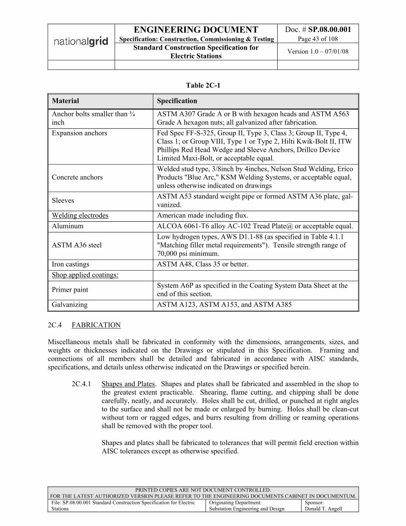
ENGINEERING DOCUMENT Doc. # SP.08.00.001Specification: Construction, Commissioning & Testing Page 43 of 108
Standard Construction Specification for Electric Stations Version 1.0 – 07/01/08
PRINTED COPIES ARE NOT DOCUMENT CONTROLLED. FOR THE LATEST AUTHORIZED VERSION PLEASE REFER TO THE ENGINEERING DOCUMENTS CABINET IN DOCUMENTUM.File: SP.08.00.001 Standard Construction Specification for Electric Stations
Originating Department:Substation Engineering and Design
Sponsor:Donald T. Angell
Table 2C-1
Material Specification
Anchor bolts smaller than ¾ inch
ASTM A307 Grade A or B with hexagon heads and ASTM A563 Grade A hexagon nuts; all galvanized after fabrication.
Expansion anchors Fed Spec FF-S-325, Group II, Type 3, Class 3; Group II, Type 4, Class 1; or Group VIII, Type 1 or Type 2, Hilti Kwik-Bolt II, ITW Phillips Red Head Wedge and Sleeve Anchors, Drillco Device Limited Maxi-Bolt, or acceptable equal.
Concrete anchorsWelded stud type, 3/8inch by 4inches, Nelson Stud Welding, Erico Products "Blue Arc," KSM Welding Systems, or acceptable equal, unless otherwise indicated on drawings
Sleeves ASTM A53 standard weight pipe or formed ASTM A36 plate, gal-vanized.
Welding electrodes American made including flux.Aluminum ALCOA 6061-T6 alloy AC-102 Tread Plate@ or acceptable equal.
ASTM A36 steelLow hydrogen types, AWS D1.1-88 (as specified in Table 4.1.1 "Matching filler metal requirements"). Tensile strength range of 70,000 psi minimum.
Iron castings ASTM A48, Class 35 or better.Shop applied coatings:
Primer paint System A6P as specified in the Coating System Data Sheet at the end of this section.
Galvanizing ASTM A123, ASTM A153, and ASTM A385
2C.4 FABRICATION
Miscellaneous metals shall be fabricated in conformity with the dimensions, arrangements, sizes, and weights or thicknesses indicated on the Drawings or stipulated in this Specification. Framing and connections of all members shall be detailed and fabricated in accordance with AISC standards, specifications, and details unless otherwise indicated on the Drawings or specified herein.
2C.4.1 Shapes and Plates. Shapes and plates shall be fabricated and assembled in the shop to the greatest extent practicable. Shearing, flame cutting, and chipping shall be done carefully, neatly, and accurately. Holes shall be cut, drilled, or punched at right angles to the surface and shall not be made or enlarged by burning. Holes shall be clean-cut without torn or ragged edges, and burrs resulting from drilling or reaming operations shall be removed with the proper tool.
Shapes and plates shall be fabricated to tolerances that will permit field erection within AISC tolerances except as otherwise specified.
ENGINEERING DOCUMENT Doc. # SP.08.00.001Specification: Construction, Commissioning & Testing Page 44 of 108
Standard Construction Specification for Electric Stations Version 1.0 – 07/01/08
PRINTED COPIES ARE NOT DOCUMENT CONTROLLED. FOR THE LATEST AUTHORIZED VERSION PLEASE REFER TO THE ENGINEERING DOCUMENTS CABINET IN DOCUMENTUM.File: SP.08.00.001 Standard Construction Specification for Electric Stations
Originating Department:Substation Engineering and Design
Sponsor:Donald T. Angell
Contact surfaces at all connections shall be free of loose scale, dirt, burrs, oil, and other foreign materials that would prevent solid seating of the parts.
2C.4.2 Bolting. High strength bolts and their installation and bolting tools and equipment shall conform to all requirements for A325 bolts of the "Specification for Structural Joints Using ASTM A325 or A490 Bolts" including the commentary given therewith, as approved by the Research Council on Riveted and Bolted Structural Joints of the Engineering Foundation, and endorsed by AISC, except as otherwise modified and supplemented herein. The Research Council specification is dated November 13, 1995. Bolt length shall be determined in accordance with the Research Council specification and commentary.
High strength bolted connections shall be bearing type connections with threads excluded from the shear planes except where other type connections are required by the Drawings or this Specification. Contact surfaces of bearing type connections may be painted.
Tightening of bolts shall be controlled using the "turn-of-nut" method.
2C.4.3 Anchor Bolts. Anchor bolts furnished under this Specification shall be as listed and detailed on the Drawings. Sleeves and anchor plates shall be provided where they are indicated on the Drawings. Unless otherwise indicated on the Drawings, fabrication details for all anchor bolts shall comply with ASTM A307. Anchor bolts, nuts, and washers shall be hot-dip galvanized after fabrication, threads being under-cut to provide a tolerance equal to ANSI Class 2A. Anchor bolts longer than 3 feet shall have the top 18 inches hot-dip galvanized after fabrication, threads being undercut to provide a tolerance equal to ANSI Class 2A. Each bolt without a sleeve shall be furnished with two nuts and sufficient threads to permit a nut to be installed on each side of the con-crete form or template.
2C.4.4 Iron Castings. Iron castings shall be made of tough gray pig iron, free from cracks, swells, holes, and cold shuts, and shall have a smooth finish. If galvanizing is specified, casting shall be hot-dipped galvanized in accordance with ASTM A124, A153, and A385.
2C.4.5 Embedments. Embedded materials shall be accurately fabricated and assembled. Warped or bent sections, which do not fit into the concrete forms as required, shall be replaced with suitable material. All materials embedded in concrete shall be galvanized after fabrication except steel framing members, reinforcing steel, base plates, and concrete anchors.

ENGINEERING DOCUMENT Doc. # SP.08.00.001Specification: Construction, Commissioning & Testing Page 45 of 108
Standard Construction Specification for Electric Stations Version 1.0 – 07/01/08
PRINTED COPIES ARE NOT DOCUMENT CONTROLLED. FOR THE LATEST AUTHORIZED VERSION PLEASE REFER TO THE ENGINEERING DOCUMENTS CABINET IN DOCUMENTUM.File: SP.08.00.001 Standard Construction Specification for Electric Stations
Originating Department:Substation Engineering and Design
Sponsor:Donald T. Angell
2C.5 WELDING
Except as otherwise specified, all welds, welding, and related operations for steel shall be in conformity with the applicable provisions of the AWS Structural Welding Code, AWS D1.1-88 as issued by the American Welding Society.
Except as otherwise specified, welding shall be performed using only those joint details and welding procedures which are pre-qualified in accordance with the referenced AWS code.
All welding procedures shall be submitted to the Owner for review prior to beginning the work.
All welders, welding operators, and tackers shall be tested and examined by an independent testing laboratory in accordance with the applicable provisions of the referenced AWS code. Accurate records of welder, welding operator, and tacker qualifications shall be certified and maintained by the Contractor and shall be made available to the Owner upon request.
Only E71T-1 and E71T-5 electrodes with supplemental shielding gas will be permitted when using the flux cored arc welding process.
Low hydrogen electrodes shall be stored and handled during use in a manner that will maintain their low hydrogen characteristics. The methods used for storage and handling shall be fully explained in the welding procedures submitted or in a separate electrode storage and handling procedure submitted to the Owner for review prior to beginning the work.
All welded joints exposed in exterior locations or subject to submergence in any location shall be provided with continuous welds along all contact edges except as prohibited in Article 8.8.5 of the referenced code.
Welds that are not dimensioned on the Drawings shall be sized to develop the full strength of the least strength component involved in the connection.
All welds shall be properly identified on the detailed shop drawings and shall be subject to acceptance by the Owner.
Components to be welded shall be accurately positioned and shall be rigidly secured during welding.
2C.5.1 General Inspection. The Contractor shall be responsible for inspection of the work to assure conformance to the requirements of these documents. Personnel responsible for visual inspection and acceptance of welding shall be Certified Welding Inspectors qualified and certified in accordance with American Welding Society AWS QC1, Standard for Qualification and Certification of Welding Inspectors.
Personnel performing welding inspection shall be responsible for verifying that all aspects of the welding operation are in accordance with the requirements defined in Section 6 of the referenced edition of AWS D1.1.

ENGINEERING DOCUMENT Doc. # SP.08.00.001Specification: Construction, Commissioning & Testing Page 46 of 108
Standard Construction Specification for Electric Stations Version 1.0 – 07/01/08
PRINTED COPIES ARE NOT DOCUMENT CONTROLLED. FOR THE LATEST AUTHORIZED VERSION PLEASE REFER TO THE ENGINEERING DOCUMENTS CABINET IN DOCUMENTUM.File: SP.08.00.001 Standard Construction Specification for Electric Stations
Originating Department:Substation Engineering and Design
Sponsor:Donald T. Angell
2C.5.2 Aluminum Welding. Welding and brazing of aluminum shall be in accordance with the recommendations of the Aluminum Company of America, as contained in its latest publications "Welding of Alcoa Aluminum" and "Brazing of Alcoa Aluminum." All welding rod, filler wire, brazing wire, flux, and other materials used in such welding shall be as recommended by the Aluminum Company of America for use in conjunction with the alloy to be welded in each case.
Welding procedure qualification and welder qualification shall be performed in accordance with ASME B and PVC, Section IX. All welding procedures and procedure qualification reports (PQRs) shall be submitted to the Owner for review prior to beginning the work.
Workmanship standards for the production work for weld size reinforcement, fitting, camber, tilt, defect sizes, etc., shall comply with Sections 3 and 8 of AWS D1.1.
2C.6 GALVANIZING
Metal materials which are specified herein or indicated on the Drawings to be galvanized shall be hot-dip galvanized in accordance with ASTM A123, ASTM A153, and ASTM A385. Materials specified to be galvanized shall be prepared for galvanizing by being properly cleaned, pickled, rinsed, and dried. The cleaned materials shall be immediately galvanized before any rusting can occur.
2C.7 SHOP PAINTING
Unless specifically exempted, all non galvanized steel materials shall be painted with one coat of metal primer paint after shop fabrication and before moving from the fabricating shop or manufacturing plant. Surfaces shall be dry and of proper temperature when painted, and free of grease, oil, dirt, dust, grit, rust, loose mill scale, weld flux, slag, weld spatter, or other objectionable substance. Surfaces shall be cleaned in accordance with SSPC Surface Preparation Specification No. 6 Commercial Blast Cleaning.
All shop primer paint shall be purchased from the same manufacturer.
Cleaned surfaces shall be kept dry and clean and shall be prime coated within 8 hours after cleaning.
All shop paint shall be applied in a skillful manner by acceptable methods which will provide a closely adhering coating of uniform thickness. Should materials which have been shop coated arrive on the jobsite with an inadequate or damaged coating, or a coating which is not free of sags, blisters, and runs or shows evidence of being handled or loaded before the paint has properly set, the Contractor shall be responsible for removing any rust that has formed, cleaning the surface, and applying an adequate and defect free coat of the primer paint.
No shop paint shall be applied to surfaces within 3 inches of any field welded connection.
During painting, the ambient temperature shall not be below 50°F. During damp or wet weather all painting shall be done in a dry shelter.
Materials shall not be handled in any manner until the shop paint is dry, hard, and able to resist abrasion.
ENGINEERING DOCUMENT Doc. # SP.08.00.001Specification: Construction, Commissioning & Testing Page 47 of 108
Standard Construction Specification for Electric Stations Version 1.0 – 07/01/08
PRINTED COPIES ARE NOT DOCUMENT CONTROLLED. FOR THE LATEST AUTHORIZED VERSION PLEASE REFER TO THE ENGINEERING DOCUMENTS CABINET IN DOCUMENTUM.File: SP.08.00.001 Standard Construction Specification for Electric Stations
Originating Department:Substation Engineering and Design
Sponsor:Donald T. Angell
2C.8 ERECTION
Metal materials shall be erected in accordance with AISC, the Drawings, and this Specification. Unless specified otherwise, erection tolerances shall be the same as those specified hereinbefore under the article titled FABRICATION.
All parts shall be assembled accurately and match marks shall be carefully followed. Light drifting to draw the parts together will be acceptable, but drifting to match unfair holes will not be acceptable. Any enlargements of holes necessary to make connections in the field shall be done by reaming with twist drills, care being taken not to weaken the adjoining metal. Enlarging of holes by burning is prohibited. Connections requiring extensive hole enlargements or adjustments, other than provided for by shop fabricated slotted holes, shall be brought immediately to the Owner's attention. The necessary adjustments shall be made under the direction of the Owner.
Anchor bolts and other materials embedded in concrete shall be installed as specified in the section titled CAST-IN-PLACE CONCRETE.
Installation of high strength bolts, bolting tools and equipment, and tightening of high strength bolts shall be the same as specified hereinbefore under the article titled BOLTING.
2C.8.1 Field Welding Field welding shall conform to the requirements specified under the article titled WELDING, and to these additional requirements. Each welding operator shall be qualified for all welding positions required in a joint that he welds. The entire weld of any structural joint shall be made by one operator.
It shall be the responsibility of the Contractor to have all welders, welding operators, and tackers tested and examined by an independent testing laboratory in accordance with applicable code requirements before work is begun. Qualification shall be made in accordance with the AWS Structural Welding Code, AWS D1.1--88.
2C.9 TOUCHUP PAINTING
Damaged or inadequate paint films of shop painted miscellaneous metal materials, and all accessible surfaces of field welds and connection bolts, shall be cleaned and prime painted as specified in the Coating System Data Sheet, System A6P at the end of this section.
2C.10 SPECIAL COATINGS FOR ALUMINUM SHAPES AND PLATES
Aluminum surfaces which will be in contact with dissimilar metals shall be heavily coated with zinc chromate pigment, synthetic resin type paint. Aluminum surfaces which will be in contact with concrete or mortar shall be given a heavy coat of alkali resistant bituminous paint. Bituminous paint shall be Koppers "Bitumastic No. 50" coal tar paint.
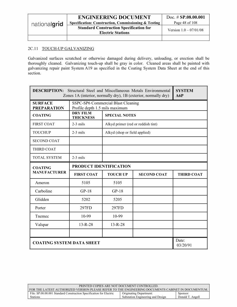
ENGINEERING DOCUMENT Doc. # SP.08.00.001Specification: Construction, Commissioning & Testing Page 48 of 108
Standard Construction Specification for Electric Stations Version 1.0 – 07/01/08
PRINTED COPIES ARE NOT DOCUMENT CONTROLLED. FOR THE LATEST AUTHORIZED VERSION PLEASE REFER TO THE ENGINEERING DOCUMENTS CABINET IN DOCUMENTUM.File: SP.08.00.001 Standard Construction Specification for Electric Stations
Originating Department:Substation Engineering and Design
Sponsor:Donald T. Angell
2C.11 TOUCH-UP GALVANIZING
Galvanized surfaces scratched or otherwise damaged during delivery, unloading, or erection shall be thoroughly cleaned. Galvanizing touch-up shall be gray in color. Cleaned areas shall be painted with galvanizing repair paint System A19 as specified in the Coating System Data Sheet at the end of this section.
DESCRIPTION: Structural Steel and Miscellaneous Metals Environmental Zones 1A (interior, normally dry), 1B (exterior, normally dry)
SYSTEMA6P
SURFACE PREPARATION
SSPC-SP6 Commercial Blast CleaningProfile depth 1.5 mils maximum
COATING DRY FILMTHICKNESS SPECIAL NOTES
FIRST COAT 2-3 mils Alkyd primer (red or reddish tint)
TOUCHUP 2-3 mils Alkyd (shop or field applied)
SECOND COAT
THIRD COAT
TOTAL SYSTEM 2-3 mils
PRODUCT IDENTIFICATIONCOATING MANUFACTURER FIRST COAT TOUCH UP SECOND COAT THIRD COAT
Ameron 5105 5105
Carboline GP-18 GP-18
Glidden 5202 5205
Porter 297FD 297FD
Tnemec 10-99 10-99
Valspar 13-R-28 13-R-28
COATING SYSTEM DATA SHEET Date:03/20/91

ENGINEERING DOCUMENT Doc. # SP.08.00.001Specification: Construction, Commissioning & Testing Page 49 of 108
Standard Construction Specification for Electric Stations Version 1.0 – 07/01/08
PRINTED COPIES ARE NOT DOCUMENT CONTROLLED. FOR THE LATEST AUTHORIZED VERSION PLEASE REFER TO THE ENGINEERING DOCUMENTS CABINET IN DOCUMENTUM.File: SP.08.00.001 Standard Construction Specification for Electric Stations
Originating Department:Substation Engineering and Design
Sponsor:Donald T. Angell
DESCRIPTION: Structural Steel and Miscellaneous Metals Touchup for galvanized surfaces not to be painted
SYSTEMA19
SURFACE PREPARATION
SSPC-SP1 Solvent Cleaning and SSPC-SP3 Power Tool CleaningRemove Oil and Loose Rust
COATING DRY FILMTHICKNESS SPECIAL NOTES
FIRST COAT 2-3 mils Organic zinc rich (light gray color))
TOUCHUP
SECOND COAT
THIRD COAT
TOTAL SYSTEM 2-3 mils
PRODUCT IDENTIFICATIONCOATING MANUFACTURER FIRST COAT TOUCH UP SECOND COAT THIRD COAT
Carboline 676
Subox Galvanox Type 1
Tnemec 90-93
Valspar 13-F-22
ZRCZRC Cold
GalvanizingCompound
COATING SYSTEM DATA SHEET Date:03/20/91

ENGINEERING DOCUMENT Doc. # SP.08.00.001Specification: Construction, Commissioning & Testing Page 50 of 108
Standard Construction Specification for Electric Stations Version 1.0 – 07/01/08
PRINTED COPIES ARE NOT DOCUMENT CONTROLLED. FOR THE LATEST AUTHORIZED VERSION PLEASE REFER TO THE ENGINEERING DOCUMENTS CABINET IN DOCUMENTUM.File: SP.08.00.001 Standard Construction Specification for Electric Stations
Originating Department:Substation Engineering and Design
Sponsor:Donald T. Angell
DIVISION 3 – ELECTRICAL CONSTRUCTION
Section 3A (260000) - CONTRACTOR FURNISHED EQUIPMENT AND MATERIALS
3A.1 GENERAL
The Contractor shall furnish all equipment and materials, except those specified herein to be furnished by the Owner or other contractors, as required for the complete erection of the equipment
3A.2 MATERIAL LISTS
The Contractor shall furnish all the items labeled or noted as “By Field” on the drawings and material Lists contained in the Substation Field Issue. All Contractor-supplied material shall be furnished in accordance with this Specification. No substitutions are allowed without the written authorization of the Owner. Contractor shall be responsible for determining the quantities of material required.
3A.3 ENGINEERING DATA
The Contractor shall submit a minimum of two sets of drawings to the Owner for acceptance on all major items of material they are required to furnish by this Specification. The Contractor shall submit drawings which adequately indicate the general arrangement of major items of material, principles of operation, sizes, general appearance, and materials of construction.
3A.4 CORRECTION OF MANUFACTURING ERRORS
The materials shall be complete in all respects within the limits herein outlined as determined by the Owner. All manufacturing errors or omissions required to be corrected in the field shall be done by the Contractor at his expense, or if done by the Owner, the cost of the same shall be deducted from the con-tract price. Any changes shall be reflected on the As-built drawings.
3A.5 MISCELLANEOUS
The Contractor shall furnish all miscellaneous materials described in section 3C.2. The contractor is also responsible to furnish all wiring materials including STAKONS, wire markers/sleeves, wire ties, and cable identification tags.
3A.6 OPERATING POSITIONS AND CONTROL ROOM PANELBOARD LABELS
The Contractor shall furnish and install Operating Position Labels for all substation yard equipment installed by the Contractor including Owner-furnished equipment. Contractor shall also furnish and install Control Room device labels, if not previously identified and mounted by equipment manufacturer.
3A.6.1 Switchyard Operating Positions. Switchyard Operating Position labels shall beassembled from replaceable letter/number blocks or Owner-approved equal consistingof black characters on a white or yellow background. The letter blocks shall beapproximately 1 ¾” wide by 2 7/8” inches high. The letter blocks shall be fade resistant and shall be assembled on aluminum panels of 3” high by 12” wide.

ENGINEERING DOCUMENT Doc. # SP.08.00.001Specification: Construction, Commissioning & Testing Page 51 of 108
Standard Construction Specification for Electric Stations Version 1.0 – 07/01/08
PRINTED COPIES ARE NOT DOCUMENT CONTROLLED. FOR THE LATEST AUTHORIZED VERSION PLEASE REFER TO THE ENGINEERING DOCUMENTS CABINET IN DOCUMENTUM.File: SP.08.00.001 Standard Construction Specification for Electric Stations
Originating Department:Substation Engineering and Design
Sponsor:Donald T. Angell
3A.6.2 In addition, the Contractor shall provide and install all Transmission lines, feedertermination structures, and riser poles with the appropriate line and feeder numbers andphase designations. Phase designations (PH1, PH2, PH3 or A, B, C as agreed upon by the Owner) shall also be installed on the load side of all disconnect switch structures, power cable terminating structures, main bus structures, power transformers and at all VT structures.
3A.6.3 All switchyard Operating Position labels shall be attached to the equipment orstructures with stainless steel hardware.
3A.6.4 Control Room Devices. The Contractor shall provide and install all adhesive backedlabels for all control room panelboards, cabinets, junction boxes, etc. unless previouslyidentified and labeled by the device manufacturer. Adhesive labels shall be 1/2” high by 3” long, fabricated of laminated Bakelite having black surfaces and a white core,engraved in bold letters, in Arial Font, captions shall be device designation, unlessstated otherwise by Owner.
3A.6.5 Additionally, adhesive backed labels using the buyer letter and/or number designationsper the drawings are required for the rear of all devices, as well as terminal blocks, ACcircuit breakers, fuses, etc., mounted on the control wiring compartment.
3A.6.6 Each front of control or relay panelboard shall be identified with and adhesive backedlabel mounted on the top center or each panelboard unit. The adhesive label shall be1½” high by 5” long, fabricated of laminated Bakelite having black surfaces and awhite core, engraved in bold letters, in Arial Font, caption shall be the panelboarddesignation, unless stated otherwise by Owner.
Section 3B (260000) - OWNER-FURNISHED EQUIPMENT AND MATERIALS
3B.1 GENERAL
Owner-furnished equipment and materials are identified in the Substation Field Issue. Delivery dates for major pieces of Owner-furnished electrical equipment and materials are included in the Substation Field Issue. All other material and equipment not supplied by the Owner shall be supplied by the Contractor and approved by the Owner.

ENGINEERING DOCUMENT Doc. # SP.08.00.001Specification: Construction, Commissioning & Testing Page 52 of 108
Standard Construction Specification for Electric Stations Version 1.0 – 07/01/08
PRINTED COPIES ARE NOT DOCUMENT CONTROLLED. FOR THE LATEST AUTHORIZED VERSION PLEASE REFER TO THE ENGINEERING DOCUMENTS CABINET IN DOCUMENTUM.File: SP.08.00.001 Standard Construction Specification for Electric Stations
Originating Department:Substation Engineering and Design
Sponsor:Donald T. Angell
Section 3C (260529) - ELECTRICAL EQUIPMENT ERECTION
3C.1 GENERAL
The Contractor shall install electrical equipment as specified herein. Erection work for all electrical equipment installed or furnished and installed under this Specification shall include receiving, unloading, care, storage, removal from storage, hauling, cleaning, erection on foundations, and all other work nec-essary to place all equipment into successful operation. In addition, erection work shall include complete assembly of equipment shipped unassembled; dismantling and reassembly of equipment to make adjustments; and provision of personnel, equipment, and assistance to the Owner in testing and placing the equipment into operation. Erection procedures shall be in accordance with this specification and manufacturer’s recommendations and drawings. In the event of a conflict, stringent requirements shall prevail. 3C.2 MISCELLANEOUS MATERIAL
The Contractor shall furnish all tools and miscellaneous materials as required for the complete erection of the equipment. These materials shall include, but shall not be limited to, grout, shims, wedges, dowels, anchors, supports, bolting, gaskets, packing, welding rod, and consumable gases.
3C.3 EQUIPMENT PROTECTION
The Contractor shall protect all equipment from damage of any kind from the time it is unloaded until it is ready for initial operation.
3C.3.1 During the erection period, all electrical equipment having drive motors or rotating parts shall be protected with weatherproof flame resistant sheeting which completely covers the exposed parts of the equipment.
3C.3.2 Equipment shall be suitably protected from weld spatter during construction.
3C.3.3 Equipment housed or covered with glass or equipped with easily broken components shall be protected as required to prevent damage throughout the construction period.
3C.4 CLEANING
The Contractor shall clean the exterior and interior surfaces of each equipment item of sand, dirt, and other foreign materials after its removal from storage and immediately before its movement to its final location.
3C.4.1 Before initial operation of individual items of equipment, the Contractor shall remove all dirt, mortar, and other material which has been spilled, misplaced, or otherwise has been allowed to mar the finish surfaces.
3C.4.2 The interior of all electrical equipment, including relays and electrical contacts, shall be thoroughly wiped and vacuumed clean before the equipment is energized.
3C.4.3 All debris shall be removed from the site and disposed of as directed by the Owner.

ENGINEERING DOCUMENT Doc. # SP.08.00.001Specification: Construction, Commissioning & Testing Page 53 of 108
Standard Construction Specification for Electric Stations Version 1.0 – 07/01/08
PRINTED COPIES ARE NOT DOCUMENT CONTROLLED. FOR THE LATEST AUTHORIZED VERSION PLEASE REFER TO THE ENGINEERING DOCUMENTS CABINET IN DOCUMENTUM.File: SP.08.00.001 Standard Construction Specification for Electric Stations
Originating Department:Substation Engineering and Design
Sponsor:Donald T. Angell
3C.5 MAINTENANCE TOOLS
The Contractor may use special tools furnished with equipment only when authorized by the Owner. The Contractor shall store all special tools furnished with equipment for maintenance as directed by the Owner.
3C.6 MANUFACTURERS' INSPECTION AND SUPERVISION
The services of a trained manufacturer's representative to inspect and advise during the installation of Owner-furnished equipment will be supplied as required by the Owner. The Contractor shall furnish all necessary labor to perform tests or inspections as required by the manufacturer's representative.
3C.6.1 When field labor is needed to correct errors in Owner-furnished equipment, the Contractor shall furnish such labor when so requested by the manufacturer or the manufacturer's representative. The cost of such remediation labor will not be included in the payment for the work to be performed under this Specification. The Contractor shall obtain payment for this labor from the manufacturer who requests the labor.
3C.7 LOCATION TOLERANCES
Equipment shall in general, be located within l/8 inch of the dimensional location indicated on the Drawings unless otherwise indicated or permitted by the Owner.
3C.8 ALIGNMENT
The Contractor shall align and connect rigid components such as bus and enclosures with special care to prevent excessive stress in joints, supports, and connections. Equipment with moving parts such as switches, circuit breakers, and switch operating mechanisms shall be carefully aligned to assure free mechanical operation.
3C.9 BOLTED ELECTRICAL CONNECTIONS
It shall be the Contractor's responsibility to certify that the tightness of each bolt in all bolted electrical connections, factory or field, is in accordance with the manufacturer's recommendations. The Contractor shall check the tightness of each bolt in each factory made bolted electrical connection during erection and connection of the equipment.
3C.9.1 Where bolted connections are made to aluminum, the aluminum surface shall be thoroughly cleaned with a wire brush, then coated with joint compound and thoroughly brushed again through the compound. Additional compound shall then be added and the joint bolted together. Joint compound shall be Alcoa No.2.
3C.9.2 Where bolted connections are made between copper or brass surfaces, the metal surfaces shall be thoroughly cleaned and coated with Penetrox A as manufactured by Burndy Corp., Norwalk, Connecticut or No-Ox-Id A compound as manufactured by Sanchem Inc., Chicago, Illinois.

ENGINEERING DOCUMENT Doc. # SP.08.00.001Specification: Construction, Commissioning & Testing Page 54 of 108
Standard Construction Specification for Electric Stations Version 1.0 – 07/01/08
PRINTED COPIES ARE NOT DOCUMENT CONTROLLED. FOR THE LATEST AUTHORIZED VERSION PLEASE REFER TO THE ENGINEERING DOCUMENTS CABINET IN DOCUMENTUM.File: SP.08.00.001 Standard Construction Specification for Electric Stations
Originating Department:Substation Engineering and Design
Sponsor:Donald T. Angell
3C.9.3 Bolted electrical connections made with Belleville spring washers shall be tightened until the Belleville washer is completely flat. Tightening of connections with Belleville washers shall stop when the Belleville washers go flat. These connections shall not be over-tightened.
3C.9.4 Bolted electrical connections shall be tightened with manual torque wrenches. Torque wrenches shall be constructed so that they will visually or audibly indicate when the proper torque is reached. The accuracy of each torque wrench shall be checked by a testing laboratory acceptable to the Owner immediately prior to its use on equipment erected under this Specification.
3C.9.5 Torque Values. If the equipment manufacturer's erection instructions do not include recommended torque values for bolt tightening or specify an alternate method for tightening bolted electrical connections, torque values shall be in accordance with those listed in table 3C-1.
Table 3C-1TORQUE VALUES FOR DRY, UNPLATED, NONLUBRICATED BOLTS
18-8 Stainless
SteelBrass Silicon
BronzeAluminum
24ST-4
316 Stainless
SteelBolt Size
In.-lb in.-lb in.-lb in.-lb in.-lb
1/4” - 28 94 77 87 57 995/16"- 24 132 107 123 80 1383/8" - 16 236 192 219 143 2473/8" - 24 259 212 240 157 2717/16"- 14 376 317 349 228 3937/16"- 20 400 327 371 242 4181/2" - 13 517 422 480 313 5421/2" - 20 541 443 502 328 5659/16"- 12 682 558 632 413 7139/16"- 18 752 615 697 456 7875/8" - 11 1110 907 1030 715 11605/8" - 18 1244 1016 1154 798 13013/4" - 10 1530 1249 1416 980 15823/4" - 16 1490 1220 1382 958 15587/8" - 9 2328 1905 2140 1495 24307/8" - 14 2318 1895 2130 1490 24201" - 8 3440 2815 3185 2205 35951" - 14 3110 2545 2885 1995 3250
ENGINEERING DOCUMENT Doc. # SP.08.00.001Specification: Construction, Commissioning & Testing Page 55 of 108
Standard Construction Specification for Electric Stations Version 1.0 – 07/01/08
PRINTED COPIES ARE NOT DOCUMENT CONTROLLED. FOR THE LATEST AUTHORIZED VERSION PLEASE REFER TO THE ENGINEERING DOCUMENTS CABINET IN DOCUMENTUM.File: SP.08.00.001 Standard Construction Specification for Electric Stations
Originating Department:Substation Engineering and Design
Sponsor:Donald T. Angell
3C.9.6 Connection Bolt Tightness Check. The Contractor shall check the tightened bolts in electrical connections at random as selected by and in the presence of the Owner. The Contractor shall provide calibrated hand torque wrenches and the necessary platforms, equipment, and personnel for the random check.
a. The number of bolts checked shall be acceptable to the Owner based upon his observance of the quality and completeness of the tightening operations. A minimum of 10 per cent of the bolts in each connection, but not less than two bolts in each connection, shall be checked.
b. The Contractor shall be responsible for coordinating the checking of bolt tightness so that minimum interference with equipment erection and connection will be experienced. Removal of covers and similar dismantling of equipment to permit the Owner to witness the testing of bolt tightness of enclosed connections shall be part of the work included under this Specification.
c. Checking of tightness of electrical connections in the presence of the Owner is intended to assist the Contractor in avoiding the expense of repairing costly connection failures. This check shall not relieve the Contractor of complete responsibility for the integrity of the electrical connections.
d. After torquing connections (Refer to Table 3C-1), each bolted connection shall be marked with a black, indelible (waterproof, permanent) marker from the nut body to the material being bolted, to indicate that proper torque has been achieved
3C.10 WELDER QUALIFICATION
All workmen performing ferrous and aluminum welding of any kind shall be qualified according to the American Welding Society Publication AWS D1.1 and AWS D1.2, latest revisions, Structural Welding Code. The qualification testing shall be conducted by an independent testing laboratory acceptable to the Owner. The conditions of test welding shall be similar to those for the work.
3C.11 LUBRICATION
The Contractor shall furnish all oils, greases, and other lubricants required to place equipment in operation. The Contractor shall apply lubricants in accordance with the manufacturer's recommendations. The lubricants used shall be acceptable to the Owner.
ENGINEERING DOCUMENT Doc. # SP.08.00.001Specification: Construction, Commissioning & Testing Page 56 of 108
Standard Construction Specification for Electric Stations Version 1.0 – 07/01/08
PRINTED COPIES ARE NOT DOCUMENT CONTROLLED. FOR THE LATEST AUTHORIZED VERSION PLEASE REFER TO THE ENGINEERING DOCUMENTS CABINET IN DOCUMENTUM.File: SP.08.00.001 Standard Construction Specification for Electric Stations
Originating Department:Substation Engineering and Design
Sponsor:Donald T. Angell
3C.12 EQUIPMENT FINISH
Surfaces of most electrical equipment, such as panels, transformers, and circuit breakers, are finished at the factory. The Contractor shall exercise great care to prevent damage to this original finish during installation of the equipment and during construction work.
3C.12.1 If the factory finish is damaged during the course of construction, the entire surface of the damaged component shall be refinished by and at the expense of the Contractor. The refinished surface shall be equivalent in every respect to the original surface, including color, texture, and smoothness. Refinishing paint, if furnished with the equipment, may be used; otherwise, the paint shall be obtained from the equipment manufacturer.
3C.13 GALVANIZED SURFACE COATINGS
All galvanized surfaces on which the galvanizing is removed by cutting, drilling, or by any other opera-tion shall be re-galvanized with "Galvanizing Powder M-32l" as manufactured by the American Solder and Flux Company of Philadelphia, Pennsylvania; with "Zincilate 8l0" as manufactured by Industrial Metal Protectives, Inc., of Dayton, Ohio; with "Zinc Rich" coating as manufactured by ZRC Chemical Products Company, Quincy, Massachusetts; or acceptable equal. The Contractor shall furnish this protective material and shall apply it in the field to any surface where the galvanized coating is broken or removed.
3C.14 RESERVED
3C.15 RESERVED
3C.16 ERECTION OF SUBSTATION STRUCTURES
The Contractor shall erect substation structures in accordance with AISC and Aluminum Association standards, the Drawings, and this Specification.
Except as specifically indicated otherwise on the Drawings, or specified herein, all work performed in connection with substation structures under this Specification shall be in accordance with the AISC "Manual of Steel Construction”, latest revision, and the applicable provisions of the Aluminum Association "Standard for Aluminum Structures".
3C.16.1 Tolerances. All galvanized steel structures, including each vertical component thereof, shall be erected plumb within a tolerance of 1:1000. Horizontal components shall be level.
a. Structural aluminum shall be erected so that individual pieces are plumb, level, and aligned within a tolerance of 1:500. The elevation of horizontal members shall be within 1/16 inch of the elevation indicated on the Drawings.

ENGINEERING DOCUMENT Doc. # SP.08.00.001Specification: Construction, Commissioning & Testing Page 57 of 108
Standard Construction Specification for Electric Stations Version 1.0 – 07/01/08
PRINTED COPIES ARE NOT DOCUMENT CONTROLLED. FOR THE LATEST AUTHORIZED VERSION PLEASE REFER TO THE ENGINEERING DOCUMENTS CABINET IN DOCUMENTUM.File: SP.08.00.001 Standard Construction Specification for Electric Stations
Originating Department:Substation Engineering and Design
Sponsor:Donald T. Angell
b. The limit of tolerance in vertical component plumbness shall be based on the height from the baseplate to the point being plumbed and shall be measured from the true center line of the vertical component.
3C.16.2 Assembly. Components for steel or aluminum structures shall be assembled accurately as indicated on the Drawings and match marks shall be followed carefully. Light drifting will be permitted to draw the parts together, but drifting to match unfair holes will not be permitted.
a. Slight enlargement of holes necessary to make connections shall be done by reaming with twist drills; enlarging of holes by burning is prohibited. Connections requiring extensive enlargements or enlargements which would adversely affect the strength of the member or connection shall be brought immediately to the Owner’s attention and the necessary adjustments shall be made in accordance with the Owner’s instructions.
b. Before making permanent field connections, all joints shall be assembled and drawn up snugly and the structure shall be checked for alignment, plumb, and level in accordance with the specified tolerances.
c. During the assembly, fit-up, and adjustment, the structure shall be braced, guyed, and otherwise secured as required to prevent collapse or damage resulting from wind, construction operations, or other stresses.
d. Materials which become bent, warped, or otherwise damaged so that they are unsuitable for installation, in the opinion of the Owner, shall be replaced with suitable materials without expense to the Owner.
e. Where the galvanized coating of any structure component has been damaged and parent metal is exposed as a result of shipping, handling, drilling, reaming, welding, or any other cause, the damaged or exposed area shall be cleaned to white metal and repaired with a zinc rich coating, depositing not less than 2 ounces of zinc per square foot. The zinc rich coating shall be as specified in the section titled GALVANIZED SURFACE COATINGS.
3C.16.3 Bolting. The work shall be done by competent and experienced bolting crews. All methods, tools, and equipment shall be subject to the acceptance of the Owner. Bolts will be furnished by the Owner, except as otherwise indicated on the Drawings or as otherwise specified in this Specification.
a. Connection bolts for galvanized steel structures will be high strength galvanizedper ASTM A325 with washers and locking devices.
b. Connection bolts and flat washers for aluminum structures will be aluminum alloy 2024-T4 and bolts will have #205 Alumilite finish. Nuts and beveled washers for aluminum structures will be aluminum alloy 6061-T6.
ENGINEERING DOCUMENT Doc. # SP.08.00.001Specification: Construction, Commissioning & Testing Page 58 of 108
Standard Construction Specification for Electric Stations Version 1.0 – 07/01/08
PRINTED COPIES ARE NOT DOCUMENT CONTROLLED. FOR THE LATEST AUTHORIZED VERSION PLEASE REFER TO THE ENGINEERING DOCUMENTS CABINET IN DOCUMENTUM.File: SP.08.00.001 Standard Construction Specification for Electric Stations
Originating Department:Substation Engineering and Design
Sponsor:Donald T. Angell
c. All connections shall be bearing type connections with threads excluded from the shear planes of the connected materials. Bolt length shall be selected in accordance with the Research Council specification and commentary specified hereinafter. Bolt length shall provide for washers, nuts, and locking devices. Where clearance permits, nuts shall be placed so they will be on the least visible side of each connection.
d. High strength bolts and their installation and bolting tools and equipment shall conform to all requirements for A325 bolts of the "Specifications for Structural Joints Using ASTM A325 or A490 Bolts" including the commentary given therewith, as approved by the Research Council on Riveted and Bolted Structural Joints of the Engineering Foundation and endorsed by AISC, except as otherwise modified or supplemented herein. The Research Council specification is dated November 13, 1985.
e. Tightening of all bolts shall be done by the "turn-of-nut" method only. A washer shall be used under the element turned in tightening. Smooth beveled washers shall be used when the bearing faces of the bolted parts have a slope of 1:20 or greater with respect to a plane normal to the bolt axis.
f. Bolted connections shall be drifted to proper position and the holes inspected to ensure that bolt threads will not be damaged by forcing the bolts in place. Connections shall be tightly drawn together using two bolts or 25 per cent of the total number of bolts in the completed joint, whichever is greater. Bolts for initial tightening shall be distributed uniformly about the joint. Either fitting-up bolts or high strength bolts may be used for this purpose.
g. Any ASTM A325 bolt which has been tightened more than one-third turn beyond "snug tight" shall not be loosened and re-tightened. All such bolts shall be discarded and new bolts shall be used in their place.
h. The Contractor shall make a thorough inspection to ensure that all bolts are tightened and that a locknut has been installed and tightened on each bolt. The bolts shall be marked in place.
i. The tightened bolts shall be checked at random as directed by and in the presence of the Owner. A calibrated hand torque wrenches and the necessary platforms, equipment, and personnel shall be provided for the random check. The wrench shall be calibrated to indicate a torque equivalent to bolt tension of 18,000 pounds or 5/8 inch bolts. The number of bolts checked shall be acceptable to the Owner based upon his observance of the quality and completeness of the tightening operations. A minimum of l0 percent of the bolts in each connection, but not less than two bolts in each connection, shall be checked.
3C.16.4 Erection of Shielding Masts. Except as modified or supplemented by this article, substation shielding masts shall be erected in accordance with the requirements for substation structures in this Specification.
ENGINEERING DOCUMENT Doc. # SP.08.00.001Specification: Construction, Commissioning & Testing Page 59 of 108
Standard Construction Specification for Electric Stations Version 1.0 – 07/01/08
PRINTED COPIES ARE NOT DOCUMENT CONTROLLED. FOR THE LATEST AUTHORIZED VERSION PLEASE REFER TO THE ENGINEERING DOCUMENTS CABINET IN DOCUMENTUM.File: SP.08.00.001 Standard Construction Specification for Electric Stations
Originating Department:Substation Engineering and Design
Sponsor:Donald T. Angell
a. Two sets of nuts will be furnished for the mast anchor bolts. One set shall be installed on the anchor bolts and leveled before the masts are set on the bolts.
b. Each mast shall be checked with a transit for alignment and plumb. Each mast shall be plumb within l/4 inch in 10 feet of height.
c. Masts shall be grounded as soon as practicable after they are erected.
3C.17 STRUCTURAL AND MISCELLANEOUS ALUMINUM
Unless otherwise noted, all materials and work shall conform to applicable provisions of the Aluminum Association "Standard for Aluminum Structures." All members shall be Aluminum Association standard structural shapes. Fabrication work shall be in accordance with current industry practice.
3C.17.1 Connections. Connections not specifically detailed on the Drawings shall develop the full strength of the least strength member of the connection. Unless otherwise noted, connections shall be all-bolted, bearing type, utilizing 3/4 inch bolts equipped with a helical spring lock washer under the stationary element (bolt head or nut) and a flat washer under the turned element. A sufficient number of bolts shall be provided in each connection to develop the shear strength of the members. Unless otherwise noted, welded connections will not be acceptable.
3C.17.2 Field Erection. Structural aluminum shall be erected so that individual pieces are plumb, level, and aligned within a tolerance of 1:500. The elevation of horizontal members shall be within 1/16 inch of the elevation indicated on the Drawings.
3C.18 SUBSTATION ALUMINUM BUS
The Contractor shall unpack, clean, and check all aluminum bus immediately upon receipt from the carrier or Owner. The Contractor shall remove all materials which might damage the bus finish and shall store the bus in such a manner that the finish will be protected. All costs associated with the cleaning of minor black marks, abrasions, and scratches shall be included in the lump sum price.
Bus delivered by the carrier or Owner with unsatisfactory finish shall be rejected. The Contractor shall be responsible for maintaining the finish on bus accepted from the carrier. Defective bus finish discovered after initial unpacking and inspection shall be the responsibility of the Contractor. Any stored or erected bus found to have unsatisfactory finish shall be refinished or replaced by the Contractor at the option of the Owner. All expense for such refinishing or replacement shall be borne by the Contractor.
All bus shall be carefully handled and erected to provide a complete bus system without dents, abrasions, discolorations, or other structural or surface damage. Any bus so damaged shall be replaced by the Contractor at his expense.
Prior to the installation of fittings for the bus, conductor for vibration dampening, as required by the Drawings, shall be installed within all horizontal buses for the full length of each bus. The conductor for this application will be furnished by the Owner.

ENGINEERING DOCUMENT Doc. # SP.08.00.001Specification: Construction, Commissioning & Testing Page 60 of 108
Standard Construction Specification for Electric Stations Version 1.0 – 07/01/08
PRINTED COPIES ARE NOT DOCUMENT CONTROLLED. FOR THE LATEST AUTHORIZED VERSION PLEASE REFER TO THE ENGINEERING DOCUMENTS CABINET IN DOCUMENTUM.File: SP.08.00.001 Standard Construction Specification for Electric Stations
Originating Department:Substation Engineering and Design
Sponsor:Donald T. Angell
3C.18.1 Field Bends. All field bends of bus shall be made with a hydraulic type bender which is acceptable to the Owner. Each bend shall be smooth and uniform and shall retain the original inside bus diameter. Bend radii shall be as indicated on the Drawings. Each bend in 2 inch bus shall have a center line radius of at least 9-1/2 inches. Each bend in bus larger than 2 inches shall have a center line radius of at least five times the inside diameter of the bus.
3C.18.2 Alignment. All bus components shall be aligned and supported prior to and during the welding operation. Support and alignment shall be as required to provide a finished bus arrangement with center lines of adjacent sections coincident. Bus shall be aligned for welding in such a manner that the welded bus remains essentially straight after removal of erection supports. During splicing operations, each piece of bus shall be supported at not less than three points in approximately equal spans of 12 feet or less.
3C.18.3 Fittings. The joint components to be welded shall be fitted to allow for expansion and contraction during welding without loss of alignment. The joint design shall be in accordance with manufacturers' recommendations. Connections shall be positioned and located to prevent the retention of water or drainage from copper or copper alloys to aluminum surfaces. Drain holes shall be provided as required. The location and size of drain holes shall be acceptable to the Owner.
3C.18.4 Connections. Connections shall be made using Deutsch or DMC compression connectors for bus assemblies, where indicated on the drawings and material list. The Contractor is responsible for providing proper training for his field personnel in making these compression connections, as well as providing all the associated tooling, dies, and equipment necessary to perform the work.
3C.18.5 Cleaning. Immediately prior to welding, each surface to be joined by the weld shall be thoroughly cleaned. Greases, oils, waxes, etc., shall be removed by standard degreasing solutions as recommended by the manufacturer. Oxides shall be removed from the areas to be welded by vigorous scrubbing of the surfaces with stainless steel wire brushes.
ENGINEERING DOCUMENT Doc. # SP.08.00.001Specification: Construction, Commissioning & Testing Page 61 of 108
Standard Construction Specification for Electric Stations Version 1.0 – 07/01/08
PRINTED COPIES ARE NOT DOCUMENT CONTROLLED. FOR THE LATEST AUTHORIZED VERSION PLEASE REFER TO THE ENGINEERING DOCUMENTS CABINET IN DOCUMENTUM.File: SP.08.00.001 Standard Construction Specification for Electric Stations
Originating Department:Substation Engineering and Design
Sponsor:Donald T. Angell
3C.18.6 Welding. Welding processes and methods shall be subject to code qualification and acceptance by the Owner. Only the following welding methods will be permitted for joining bus sections and fittings:
Gas metal arc welding.Gas tungsten arc welding.
Shielding gas for each process shall be welding grade argon when welding material is less than ¾ inch thick. A combination of helium and argon shall be used for each process when the welding material is ¾ inch thick and greater. Welding energy and filler metal requirements shall be as recommended by AWS D10.7-86, "Recommended Practices for Gas Shielded Arc Welding of Aluminum and Aluminum Alloy Pipe." The following from AWS D10.7 shall apply:
Filler rod Table 1Rod size, gas flow, and welding current Table 2 through Table 11
3C.18.7 Welding Qualifications. The Contractor shall prepare written welding procedure specifications. The procedure shall be qualified as defined below. Welding procedure specifications, procedure qualification reports, and welder qualification reports shall be submitted to the Owner for review. Welding shall not begin until the Owner's review is complete.
a. All procedure qualification testing and welder qualification testing shall be in accordance with the methods defined in AWS D10.9-80, "Specification for Qualification of Welding Procedures and Welders for Piping and Tubing."
b. Testing shall be conducted to the requirements of AR-1 qualification level under the following conditions:
Materials P-Number 23, aluminum base alloys.Weld Groove.Position 6G.
c. All qualification testing shall be performed by an acceptable independent testing laboratory. Report formats shall be similar to the examples in AWS D10.9-80 for the following:
Typical Welding Procedure Specification (WPS).Typical Contractor's Procedure Qualification Test Record (PQR).Typical Contractor's Welder Qualification Tests Record.
d. All costs for testing, including material costs, shall be paid by the Contractor.
e. Welders, after qualification, shall not be replaced on this welding duty unless such action is acceptable to the Owner.

ENGINEERING DOCUMENT Doc. # SP.08.00.001Specification: Construction, Commissioning & Testing Page 62 of 108
Standard Construction Specification for Electric Stations Version 1.0 – 07/01/08
PRINTED COPIES ARE NOT DOCUMENT CONTROLLED. FOR THE LATEST AUTHORIZED VERSION PLEASE REFER TO THE ENGINEERING DOCUMENTS CABINET IN DOCUMENTUM.File: SP.08.00.001 Standard Construction Specification for Electric Stations
Originating Department:Substation Engineering and Design
Sponsor:Donald T. Angell
3C.18.8 Painting. If indicated on the drawings or specified in the work summary, aluminum angle, tubular and integral web busses insulated for less than 69 kV, shall be painted to ensure that they will be distinguishable from structural members. The sole purpose of the paint is to provide color identification of the bus and maintain a consistent appearance for all energized current-carrying bus conductors in a structure. It is neither necessary nor desirable to cover all connections, joints, etc., so long as coverage is sufficient for the purpose.
a. While tubular and integral-web busses are readily distinguished from structural angles, their close proximity to the structure at lower voltages makes color identification necessary. The Contractor shall furnish Rust-OleumR #K7764 –“Safety Red” and Rust-Oleum # V7769 “Rusty Metal Primer”. The Contractor shall apply the paint in accordance with the manufacturer’s surface preparation and application instructions as printed on the container.
Section 3D (260526) - GROUNDING
3D.1 GENERAL
The Contractor shall install grounding materials as indicated on the Drawings and in the Substation Field Issue and as required for a complete grounding system. The Contractor is also responsible for providing all tools, dies, and other equipment required for his crews to perform all grounding work.
3D.2 INSTALLATION
The Contractor shall install grounding system materials according to the Drawings and as specified herein. The ground grid materials shall consist of copper or copperweld as directed by the drawings or specified in the work summary within.
3D.2.1 Ground Grid. Ground grid conductors under buildings or structures shall be buried with at least 6 inches of earth cover. Buried grounding conductors extending beyond the foundations of buildings or structures shall have at least 18 inches of earth cover.
3D.2.2 Ground Rods. All ground rods shall be located as indicated on the Drawings and installed to the depth indicated. Except as otherwise indicated on the Drawings, all buried ground rods shall be installed with not less than 18 inches of earth cover.
a. The Contractor shall measure the ground resistance of a typical ground rod after each section of rods has been installed into the ground prior to connection of the ground rods to the grounding system. The resistance values measured shall be recorded on the Grounding Report. These data shall be obtained, identified, and recorded under the supervision of the Owner and records of the results sent to the Owner within 5 days.
b. Where rock is located at a depth less than the required ground rod depth below the ground surface, the Contractor shall contact the Owner, who will advise the Contractor on how to proceed.
ENGINEERING DOCUMENT Doc. # SP.08.00.001Specification: Construction, Commissioning & Testing Page 63 of 108
Standard Construction Specification for Electric Stations Version 1.0 – 07/01/08
PRINTED COPIES ARE NOT DOCUMENT CONTROLLED. FOR THE LATEST AUTHORIZED VERSION PLEASE REFER TO THE ENGINEERING DOCUMENTS CABINET IN DOCUMENTUM.File: SP.08.00.001 Standard Construction Specification for Electric Stations
Originating Department:Substation Engineering and Design
Sponsor:Donald T. Angell
3D.2.3 Conductors. Exposed conductors shall be installed inconspicuously in vertical or horizontal positions on supporting structures. When located on irregular supporting surfaces or equipment, the conductors shall run parallel to or normal to dominant surfaces. Conductors routed over concrete, structures, or equipment surfaces shall be kept in close contact with those surfaces by using fasteners located at intervals not to exceed 3 feet. Damaged ground system conductors shall be repaired or replaced by the Contractor as directed by the Owner. Except as otherwise indicated on the Drawings, all buried ground conductors shall be installed with not less than 18 inches of earth cover.
3D.2.4 Connections. All connections shall be compression fittings except where otherwise indicated on the Drawings or in this Specification. The manufacturer's instructions shall be followed in all details. If bolted and screwed connections are called for they shall be securely tightened. The proper dies and presses shall be used and manufacturer’s instructions shall be followed in all details. Bolted connections shall not be used underground, except in some cases for the ground rod clamp. Where bolted connectors are used, all bolted and screwed connections shall be securely tightened, per the manufacturer’s recommendations, unless specified otherwise within.
3D.2.5 Conduit Grounding. Where a conduit run is terminated at tray and the conduit carries a separate grounding conductor, this grounding conductor shall be terminated on the tray grounding cable.
3D.2.6 Tray Grounding. A bare grounding conductor will be provided with each cable tray system and will be installed the entire length of the cable trays, on the outer side of the tray. The Contractor shall connect the cable tray grounding conductor to the station ground grid as indicated on the Drawings.

ENGINEERING DOCUMENT Doc. # SP.08.00.001Specification: Construction, Commissioning & Testing Page 64 of 108
Standard Construction Specification for Electric Stations Version 1.0 – 07/01/08
PRINTED COPIES ARE NOT DOCUMENT CONTROLLED. FOR THE LATEST AUTHORIZED VERSION PLEASE REFER TO THE ENGINEERING DOCUMENTS CABINET IN DOCUMENTUM.File: SP.08.00.001 Standard Construction Specification for Electric Stations
Originating Department:Substation Engineering and Design
Sponsor:Donald T. Angell
3D.2.7 Equipment Grounding. Unless otherwise indicated, all electrical equipment and the control house and/or enclosure shall be connected to the ground grid with the specified grounding conductor. The term "electrical equipment," as used in this article, shall include all enclosures containing electrical connections or bare conductors. Most equipment will be furnished with grounding pads and/or grounding lugs which the Contractor shall connect to the ground grid. All ground connection surfaces shall be cleaned immediately prior to connection. The Contractor shall furnish all grounding material required but not furnished with the equipment or furnished by the Owner.
a. Where ground grid extension stingers are indicated on the Drawings to be provided for connection to electrical equipment, the Contractor shall connect the bare grounding conductor to the equipment ground bus, pad, or lug. In addition to the ground grid extension stingers, a ground conductor shall be provided from the substation ground grid to each end of the ground bus in the control house tray ground.
b. Where a ground conductor is included with the phase conductors of power circuits, the ground conductor shall be connected to the equipment grounding facilities and to the source ground bus. Where a ground conductor is not included with the phase conductors, the equipment shall be grounded by connecting a separate ground cable to the equipment grounding facilities and to the tray ground cable or source ground bus.
c. Except where otherwise indicated on the Drawings, all equipment ground conductors which are not an integral part of a cable assembly shall be sized in accordance with the requirements of NEC. All ground conductors installed in conduit shall be insulated.
d. Suitable grounding facilities, acceptable to the Owner, shall be furnished on electrical equipment not so equipped. The grounding facilities shall consist of compression type terminal connectors bolted to the equipment frame or enclosure and providing a minimum of joint resistance.
e. The conduit system is not considered to be a grounding conductor except for itself and for lighting fixtures. No grounding conductor shall be smaller in size than 12 AWG unless it is a part of an acceptable cable assembly.
ENGINEERING DOCUMENT Doc. # SP.08.00.001Specification: Construction, Commissioning & Testing Page 65 of 108
Standard Construction Specification for Electric Stations Version 1.0 – 07/01/08
PRINTED COPIES ARE NOT DOCUMENT CONTROLLED. FOR THE LATEST AUTHORIZED VERSION PLEASE REFER TO THE ENGINEERING DOCUMENTS CABINET IN DOCUMENTUM.File: SP.08.00.001 Standard Construction Specification for Electric Stations
Originating Department:Substation Engineering and Design
Sponsor:Donald T. Angell
3D.2.8 Switch Operator Safety Grounding Mat. The Switch operator safety grounding mat shall be installed as shown on the drawings or as specified in the standards listed in the Substation Field Issue. If not specifically called out in the above, the following shall apply.
A ground spiral shall be installed at the interface of the earth and crushed rock surface for all switch operators as indicated on the Drawings. The spiral shall be 4/0 AWG copper or 248.8KCM copperweld, approximately 3 foot radius and shall be connected to the station ground system and to the switch operating mechanism as indicated on the Drawings. A grounding mat is used as follows: A potential equalizing grid (10’ x 6’ x 8” mesh of #6 AWG Copperweld wire with brazed joints) shall be installed 3" below finished grade, in the crushed stone course, in front of each switch operatingmechanism location (Refer to design drawings for equalizing grid locations). Two (2) #2 AWG stranded copper conductors of adequate length shall rise from the equalizing grid to a point above the switch operating mechanism and be bonded to the ground grid riser. Each #2 AWG conductor shall run diagonally across the potential equalizing grid and be bonded to the grid in at least three (3) locations before rising above grade, as shown on the design drawings.
3D.2.9 Control/Switchgear Enclosure(s). The Contractor shall connect the control houseand/or switchgear enclosure(s) to the ground system as shown on the Drawings.
3D.2.10 Perimeter Fence. The Contractor shall connect the exterior perimeter fence to the station ground system as shown on the drawings.
3D.3 GROUND SYSTEM RESISTANCE
The Contractor shall measure the continuity of the grounding system. The entire metallic grounding system shall have low resistance continuity. After connection of ground rods to the grounding system, the Contractor shall obtain a ground resistance measurement from a selected location on the ground grid, after the grid is covered with the grounding course material. These data shall be obtained, identified, and recorded under the supervision of the Owner and records of the results sent to the Owner within 1 day.
3D.3.1 In the event that the measured value of ground resistance exceeds the calculated value specified on the drawings, the Contractor shall furnish, install, and connect additional grounding facilities as directed by the Owner. The Contractor will be reimbursed for the additional work required.
3D.3.2 The ground resistance measuring and recording procedure shall be repeated after each grounding adjustment has been completed. The Contractor shall not install more than three additional sections of ground rods at any location without prior approval from the Owner.
3D.3.3 The Contractor must receive approval from the Owner, of the grounding system resistance measurement before continuing with construction.
ENGINEERING DOCUMENT Doc. # SP.08.00.001Specification: Construction, Commissioning & Testing Page 66 of 108
Standard Construction Specification for Electric Stations Version 1.0 – 07/01/08
PRINTED COPIES ARE NOT DOCUMENT CONTROLLED. FOR THE LATEST AUTHORIZED VERSION PLEASE REFER TO THE ENGINEERING DOCUMENTS CABINET IN DOCUMENTUM.File: SP.08.00.001 Standard Construction Specification for Electric Stations
Originating Department:Substation Engineering and Design
Sponsor:Donald T. Angell
3D.4 GROUND RESISTANCE MEASUREMENTS
All ground resistance measurements shall be made with a three terminal "megger" type ground tester which applies alternating current to the electrodes and which gives a reading in direct current ohms. Two reference ground probes shall be used and all tests shall be made in accordance with the instrument manufacturer's instructions for ground resistance testing. Some of the acceptable instruments are as follows:
• Meg and megger ground testers, Megger Corp.• Vibroground, Associated Research, Inc. (Limited availability NY)• Ground-Ohmer, Herman H. Sticht Co., Inc. (Limited availability NY)• AEMC Instruments Models 4500 & 4600
3D.5 GROUNDING REPORTS
The Contractor shall maintain a record of the condition of the grounding facilities at each location throughout the construction period. A standard form entitled Grounding Report shall be prepared by the Contractor. The form shall provide space to report dimensions, depths, resistance measurements and the date each measurement was taken, revisions to the grounding arrangement indicated on the Drawings, and other pertinent information. A copy of this form shall be completed for each location and shall be turned over to the Owner at the conclusion of the project as an "as built" record.
3D.6 INSTALLATION DETAILS
3D.6.1 The Contractor shall repair as necessary, any portion of the grounding system previously installed, if disturbed during the performance of this Contract.
3D.6.2 At the start and finish of the grounding installation work; The Contractor shall make ground grid measurements and supply this information to the Owner for further use. The Contractor is responsible for ensuring that this information is taken prior to starting the grounding work and for notifying the Owner after finishing the grounding work.
3D.6.3 The Contractor shall store the ground materials properly to prevent theft, damage, deterioration and inclusion of foreign matter. Packaged materials delivered in original unopened containers must be stored in weatherproof enclosures.
3D.6.4 All electrical cabinets, pull boxes, and junction boxes, etc. shall be grounded.
3D.6.5 The Contractor shall comply with the provisions of the following codes and standards, unless more stringent requirements are specified in this document or on the drawings.
a. National Electric Code 2005 Edition, NFPA70-2005
b. The Owner’s compilation of grounding standards which are part of the Electric Station Standards for the Owner’s jurisdiction.
ENGINEERING DOCUMENT Doc. # SP.08.00.001Specification: Construction, Commissioning & Testing Page 67 of 108
Standard Construction Specification for Electric Stations Version 1.0 – 07/01/08
PRINTED COPIES ARE NOT DOCUMENT CONTROLLED. FOR THE LATEST AUTHORIZED VERSION PLEASE REFER TO THE ENGINEERING DOCUMENTS CABINET IN DOCUMENTUM.File: SP.08.00.001 Standard Construction Specification for Electric Stations
Originating Department:Substation Engineering and Design
Sponsor:Donald T. Angell
3D.6.6 When not called out specifically on the Bill of Materials, and/or the drawings the Contractor shall adhere to the following minimum grounding material requirements.
a. Ground Grid Risers & Ground Cables. Wire #4/0 AWG bare 19 str. copper single uncoated conductor with concentric lay Class B round stranding in accordance with the current ASTM Std. B8. Temper shall be soft or annealed drawn in accordance with ASTM B3. Standard shipping quantity shall be 100 lb. (app. 153 feet) coil.
b. Connector, (above grade) mechanical 2 bolt type for #4/0 stranded copper.
c. Conduit clamp, steel, ground 1¼” to 4" heavy duty, corrosion resistant with silicon bronze hardware, furnished with a mechanical grounding cable connector permitting the grounding cable to be attached parallel with or at right to angles to the steel conduit having a range of #4 solid to #4/0 stranded awg., in accordance with UL standards.
d. Connector, copper, compression type, Cross and Tee connection for use with copper conductor. Range #4/0 – 250kcmil cable to same or to ground rod. Used for connectors (underground) for #4/0 to #4/0 ground grid cable and #4/0 to ground rod connections.
e. Wire, copper, #2 stranded. Used for conduit bonding, equipotential grid bonding, etc.)
f. Connector copper C-Type range taking compression tap connection for use with
copper conductor Range 3/0 solid - 4/0 stranded run 6 solid -2 stranded tap.
g. Connector #2 solid - 250 kcmil copper cable to flat cast copper alloy body. Bolt nut and lock washer made of silicone bronze.
h. Connector, cable to flat, for two #2 sol. - 250 kcmil copper cables. Cast copperalloy body. Bolt, nut and lockwasher, silicone bronze.
Section 3E (260533) - RACEWAYS
3E.1 GENERAL
The Contractor shall install a complete raceway system in accordance with this Specification, the Conduit & Cable Schedule, and the Drawings.
3E.1.1 The raceway system is defined to include conduit, flexible conduit, continuous rigid cable supports called "cable tray" herein, underground duct, cable trench wire-way, cabinets and boxes, and all materials and devices required to install, support, secure and provide a complete system for support and protection of electrical conductors.

ENGINEERING DOCUMENT Doc. # SP.08.00.001Specification: Construction, Commissioning & Testing Page 68 of 108
Standard Construction Specification for Electric Stations Version 1.0 – 07/01/08
PRINTED COPIES ARE NOT DOCUMENT CONTROLLED. FOR THE LATEST AUTHORIZED VERSION PLEASE REFER TO THE ENGINEERING DOCUMENTS CABINET IN DOCUMENTUM.File: SP.08.00.001 Standard Construction Specification for Electric Stations
Originating Department:Substation Engineering and Design
Sponsor:Donald T. Angell
3E.2 CODES AND STANDARDS
Raceway system materials and devices furnished will be in accordance with applicable standards of ANSI, NEMA, and UL. Raceway system components shall be installed in accordance with applicable requirements of the NEC. In case of conflict between the requirements of any of the above referenced codes and standards and the requirements of this Specification, the requirements of this Specification shall govern. All materials and devices will be in accordance with the applicable requirements of the Federal "Occupational Safety and Health Standards."
3E.3 GENERAL INSTALLATION REQUIREMENTS
The installation requirements included herein apply to all raceway system components.
3E.3.1 Routing of Above-Grade Raceway. Electrical cable tray shall be routed as indicated on the Drawings. The Contractor shall field route conduit according to the general routing indicated on the Drawings and shall coordinate conduit locations with other equipment and structures.
3E.3.2 Insulation. All supports for raceway connected to equipment, raceways, etc., that have been electrically insulated from contact with other conducting structures shall be properly installed to prevent shunting of the insulation.
3E.3.3 Sleeves and Openings. The Contractor shall be responsible for making all required openings for cables and raceways. The Contractor shall be responsible for finishing all openings for cables and raceways. Openings shall not be closed until all the cables through the openings have been installed and tested. Installation of materials shall be in accordance with the manufacturer's recommendations. The materials shall be finished to provide a smooth, neat appearance.
a. Control/Switchgear Enclosures Required openings not provided during the control/switchgear enclosure fabrication shall be provided by the Contractor using a hacksaw, a hole saw, or a core drill subject to acceptance by the Owner. Openings in metal floors and walls for single conduit shall be cut by the Contractor and the conduit sealed in place after being installed.
b. Finishing Conduit Openings Beneath Equipment. Where the cables are in conduits and the conduits project through the openings, openings beneath equipment shall be closed with Carboline Pyrofoam 700 or acceptable equal.

ENGINEERING DOCUMENT Doc. # SP.08.00.001Specification: Construction, Commissioning & Testing Page 69 of 108
Standard Construction Specification for Electric Stations Version 1.0 – 07/01/08
PRINTED COPIES ARE NOT DOCUMENT CONTROLLED. FOR THE LATEST AUTHORIZED VERSION PLEASE REFER TO THE ENGINEERING DOCUMENTS CABINET IN DOCUMENTUM.File: SP.08.00.001 Standard Construction Specification for Electric Stations
Originating Department:Substation Engineering and Design
Sponsor:Donald T. Angell
c. Finishing Cable Openings Beneath Equipment. Where the cables entering the equipment are not in enclosing raceways, the openings shall be closed with Dow Corning 3-6548 silicone RTV foam, Manville Type 103 Cera Form board, or acceptable equal flame retardant materials. The Cera Form boards shall be not less than 1 inch thick and shall be cut to fit closely around the outside surfaces of the cable where the cable passes through the boards. The boards shall be securely placed in the floor opening and all openings around the cables and the boards shall be sealed with Manville Cerablanket or acceptable equal and all exposed surfaces of the board and Cerablanket shall be covered with a 1/8 inch thick coating of Carboline Intumastic 285.
d. Unused openings beneath equipment shall be closed with Carboline Pyrofoam 700, Manville Cera Form board coated with a 1/8 inch thick coating of Carboline Intumastic 285, Dow Corning 3-6548 silicone RTV foam, or acceptable equal flame retardant materials.
3E.3.4 Extensions of Building Metal to Support Raceway. Extensions of building structures to support raceway shall be of the same material as the structure being extended and shall be finished to match the finish of the extended structure.
3E.3.5 Beam Clamps. Beam clamps for attachment of hanger rods to structural metal shall be electro-galvanized steel as manufactured by Unistrut, Globe Strut, or acceptable equal.
3E.3.6 Welding. All welding shall completely fuse the welded member to the supporting metal and shall be neat in appearance. All welds shall be made by welders whose quality of work is equivalent to that of welders certified by the American Welding Society.
a. Clamps shall be used for making attachments to structural metal for installation purposes wherever possible. Welded lugs will be permitted only when acceptable to the Owner. The Contractor will apply a protective primer paint equal to that which was initially applied in the shop.
b. All temporary supports which have been welded to the building metal shall beremoved as promptly as possible. After removal, the roughened surface of the building metal shall be ground smooth and a protective primer paint applied equal to that which was initially applied in the shop.
3E.3.7 Use of Unfinished Raceway. Unfinished runs of raceway shall not be used. Supports and connections for each raceway run shall be completed prior to the pull-in of any pulling line or conductor.

ENGINEERING DOCUMENT Doc. # SP.08.00.001Specification: Construction, Commissioning & Testing Page 70 of 108
Standard Construction Specification for Electric Stations Version 1.0 – 07/01/08
PRINTED COPIES ARE NOT DOCUMENT CONTROLLED. FOR THE LATEST AUTHORIZED VERSION PLEASE REFER TO THE ENGINEERING DOCUMENTS CABINET IN DOCUMENTUM.File: SP.08.00.001 Standard Construction Specification for Electric Stations
Originating Department:Substation Engineering and Design
Sponsor:Donald T. Angell
3E.4 ELECTRICAL CONDUIT SYSTEM
The Contractor shall install an electrical conduit system in accordance with the Drawings and this Specification. The Contractor shall be responsible for the sizing and routing of all conduits including but not limited to indoor and outdoor lighting, power, fire, & heating conduits. Conduit layout and conduit riser details are shown on the detailed design drawings.
3E.4.1 Above Grade Conduit Installation. Conduit installation shall be as indicated on the Drawings and as described in this Specification.
a. Routing. Except as otherwise specified or indicated on the Drawings, all conduit shall be installed in exposed runs parallel or perpendicular to dominant surfaces with right angle turns made of symmetrical bends or fittings. Except where prevented by the location of other work, a single conduit or a conduit group shall be centered on structural members. All conduit field routing shall be acceptable to the Owner. Routing which is not acceptable shall be rerouted and replaced without expense to the Owner. All conduits shall be tagged at both ends. A tag numbering system shall be provided and installed by the Contractor that is consistent with the Owner’s drawings.
b. Moisture Pockets. Moisture pockets shall be eliminated from conduits.
c. Couplings and Unions. Metal conduit shall be joined by threaded conduit couplings with the conduit ends butted. The use of running threads will not be permitted. Where metal conduit cannot be joined by standard threaded couplings, conduit unions or split couplings may be used if their location is acceptable to the Owner. Only ground seat type watertight unions shall be used outdoors. Where Erickson type couplings or similar unions which do not have ground seats are usedin vertical or inclined conduit runs, the coupling nut shall be installed uppermost toprevent the entrance of water into the union. Couplings, unions and fittings shouldbe threaded-type, galvanized steel, B17.
d. Bends and Offsets. A run of conduit shall not contain more than the equivalent of four quarter bends, including those immediately at outlets or fittings. Bends in conduit shall be made without reducing the internal diameter of the conduit. The use of a pipe tee or vise for bending conduit will not be permitted. The inside radius of conduit bends shall be not less than six times the inside diameter of the conduit. Conduits deformed or crushed in any way shall be removed from the job site. All conduit Bend Radii shall be in accordance with the NEC.
e. Cutting and Threading. The plane of all conduit ends shall be square with the center line. Where threads are required, they shall be cut and cleaned prior to conduit reaming. The ends of all conduit shall be reamed to remove all rough edges and burrs. A cutting oil shall be used in threading operations. The dies shall be kept sharp and provisions shall be made for chip clearance.

ENGINEERING DOCUMENT Doc. # SP.08.00.001Specification: Construction, Commissioning & Testing Page 71 of 108
Standard Construction Specification for Electric Stations Version 1.0 – 07/01/08
PRINTED COPIES ARE NOT DOCUMENT CONTROLLED. FOR THE LATEST AUTHORIZED VERSION PLEASE REFER TO THE ENGINEERING DOCUMENTS CABINET IN DOCUMENTUM.File: SP.08.00.001 Standard Construction Specification for Electric Stations
Originating Department:Substation Engineering and Design
Sponsor:Donald T. Angell
f. Connections to Boxes and Cabinets. Conduit shall be securely fastened to all boxes and cabinets. Threads on metallic conduit shall project through the wall of the box to allow the bushing to butt against the end of the conduit. The locknuts both inside and outside shall then be tightened sufficiently to bond the conduit securely to the box. Conduit entering some devices, boxes and enclosures shall enter through hubs or threaded openings.
g. Cleaning. Precautions shall be taken to prevent the accumulation of water, dirt, or concrete in the conduit. Conduit in which water or other foreign materials have been permitted to accumulate shall be thoroughly cleaned or, where such accumulation cannot be removed by methods acceptable to the Owner, the conduit shall be replaced.
h. Flexible Conduit. Flexible conduit inserts shall be installed in accordance with the Drawings and the manufacturer’s recommendations.
i. Plastic Conduit. Polyvinyl chloride conduit shall be installed in accordance with the installation requirements specified for metallic conduit except that joints will be unthreaded solvent cement type as recommended by the conduit manufacturer. The contact surfaces of the conduit and fitting socket shall be cleaned with Stoddard solvent, methyl ethyl ketone, or acetone, liberally coated with solvent cement, promptly and fully engaged, and either conduit or fitting rotated approximately l/4 turn to dispel air and evenly distribute solvent cement over contact surfaces. For proper connection, total elapsed time between the start of the cement application to the surfaces being joined and final assembly of the joint should not exceed 60 seconds. The initial strength of the joint will permit continuous conduit installation; however, additional stress at the joint shall be avoided for at least 24 hours after joining.
j. Spacing and Attachment of Supports. All conduit runs shall be rigidly supported. Each conduit shall be supported within one foot of junction boxes and fittings. Support spacing along conduit runs shall be a minimum of every 3 feet or as required to provide a sturdy support. Conduit clamps shall be bolted to metal structures using drilled and tapped screw holes.
k. Codes and Standards. Comply with the provisions of the following codes, specifications and standards, except where more stringent requirements are shown or specified.
1. The Owner’s Above Ground Standards for Conduit 2. National Electric Code latest edition, NFPA 70
l. ID Numbers. Conduit ID Numbers per the conduit and cable schedule shall besecurely affixed at both ends of the conduit with aluminum stamped ID tags; or engineering approved equivalents.

ENGINEERING DOCUMENT Doc. # SP.08.00.001Specification: Construction, Commissioning & Testing Page 72 of 108
Standard Construction Specification for Electric Stations Version 1.0 – 07/01/08
PRINTED COPIES ARE NOT DOCUMENT CONTROLLED. FOR THE LATEST AUTHORIZED VERSION PLEASE REFER TO THE ENGINEERING DOCUMENTS CABINET IN DOCUMENTUM.File: SP.08.00.001 Standard Construction Specification for Electric Stations
Originating Department:Substation Engineering and Design
Sponsor:Donald T. Angell
m. Conduit Sizing. Conduits shall be sized in accordance with the NEC code requirements and as shown on the drawings.
n. Rigid Steel Conduit. The conduit risers and below grade bends shall be in accordance with the Owner’s drawings. Other requirements are as follows:
1. Material: GRC or Mild steel with continuous welded seam.2. External protective coating: Metallic zinc applied by hot-dip galvanizing or
electrogalvanizing; coating shall not flake or crack when conduit is bent.3. Interior surface: Protected by zinc, enamel, or engineering approved
equivalent corrosion-resistant coating.4. Manufacturer: Republic Steel "Galvite", Triangle PWC, Allied Tube and
Conduit Corporation "GRC", or engineering approved equivalent.5. Applicable Standards: ANSI C80.1, NEMA FB1, UL6, Federal Specification
WW-C-58LD and ANSI C80.
3E.4.2 Below Grade Conduit. The Contractor shall field route conduit according to the general routing indicated on the Drawings and shall coordinate conduit locations with other work and existing equipment above and below grade. Conduit shall be accurately positioned and securely anchored before backfilling. Conduit which will be visible above the finished grade shall be straight and plumb. Conduit which is stubbed shall be plugged prior to backfilling and shall remain plugged until the conduit is extended later. Underground conduits shall be galvanized rigid steel GRC or PVC types.
a. Bends shall be made from straight conduit lengths or shall be factory fabricated. Bend Radii shall be in accordance with the NEC. The conduit length for field bending shall be heated to approximately 275 F by radiant heat, hot air, or hot liquid immersion. Open flame heating will not be permitted. Special mandrels or forms shall be used to provide a smooth bend without reduction of the conduit diameter. Conduit discolored by prolonged heating will not be acceptable.
b. Where plastic conduit is required to be buried directly in the earth as indicated on the Drawings, a minimum of 4 inches of washed, screened sand shall be placed under, beside, around, and on top of all conduit. Backfill above the washed, screened sand layer shall be screened sand, medium mesh, and shall be approximately 18 inches deep. Backfill shall not contain stones greater than one inch in any dimension, and shall not contain ashes, cinders, shell, or frozen material.
c. Intermediate and base spacers for 1-1/2" separation between ducts and 3 inches beneath ducts shall be installed for conduit runs containing more than two (2) conduits. Intermediate spacers shall be used as caps on the top tier. Spacers shall not exceed 5 foot intervals and shall be placed at each coupling. The trench bottom shall be solid, undisturbed earth. Pockets of unsuitable soil shall be replaced with compacted sand. A minimum of 4 inches of washed, screened sand shall be placed beside the duct layout. A minimum of 3 inches of washed, screened sand shall be placed on top of the duct layout measured from the top of the top-most conduit. An 18 inch layer of backfill shall be placed upon the washed, screened sand.

ENGINEERING DOCUMENT Doc. # SP.08.00.001Specification: Construction, Commissioning & Testing Page 73 of 108
Standard Construction Specification for Electric Stations Version 1.0 – 07/01/08
PRINTED COPIES ARE NOT DOCUMENT CONTROLLED. FOR THE LATEST AUTHORIZED VERSION PLEASE REFER TO THE ENGINEERING DOCUMENTS CABINET IN DOCUMENTUM.File: SP.08.00.001 Standard Construction Specification for Electric Stations
Originating Department:Substation Engineering and Design
Sponsor:Donald T. Angell
3E.4.3 Plastic Conduit Fittings for Underground Use
a. Uses and limitations: Below finished floor
b. Conduit shall be Carlon PVC, Type 40, 90°C UL rated or engineering approved equivalent. Conduit shall be composed of polyvinyl chloride and shall conform toNEMA standards. It shall be UL listed in conformity with Article 347 of the NEC.
c. Fittings: For use with Schedule 40 PVC by same manufacturer.
d. Material: Polyvinyl chloride (PVC) plastic compound.
e. Fittings shall withstand temperatures of power cables operating at 90°C installed within.
f. Threadless type: connect to conduit by solvent cement process.
g. Adapter fittings:1. For connection of plastic conduit to rigid steel conduit.2. Threadless connection to plastic, threaded connection to rigid steel, female-
type.3. Expansion coupling.
h. Couple lengths of conduit together using solvent cement connections.
i. Manufacturer: Carlon Plus 40 Rigid Non-metallic Conduit, Part No. 49011-20,(Schedule 40), or buyer approved equal.
j. Standards: NEMA TC-2 and TC-3.
3E.4.4 Electrical Metallic Tubing (EMT):
a. Uses permitted: Building interior
b. EMT: FSWW-C-563 galvanized tubing
c. Fittings and Conduit Bodies: ANSI/NEMA FB1; steel or malleable iron, compression type.
3E.4.5 Liquid-tight Flexible Conduit:
a. Heavy galvanized steel core, Type OR-H.
b. Oil resistant thermoplastic cover, grey color.
c. Integral ground wire, sizes 1” inch to 2” inches or per NEC Code.

ENGINEERING DOCUMENT Doc. # SP.08.00.001Specification: Construction, Commissioning & Testing Page 74 of 108
Standard Construction Specification for Electric Stations Version 1.0 – 07/01/08
PRINTED COPIES ARE NOT DOCUMENT CONTROLLED. FOR THE LATEST AUTHORIZED VERSION PLEASE REFER TO THE ENGINEERING DOCUMENTS CABINET IN DOCUMENTUM.File: SP.08.00.001 Standard Construction Specification for Electric Stations
Originating Department:Substation Engineering and Design
Sponsor:Donald T. Angell
d. For high/low temperature applications use Type H.C.
e. Use steel, gasketed, insulated throat, compression type, Liquid-tight fittings.1. Bushings for metal conduit terminations shall be the nylon insulated type
throat, with grounding type locknut ahead of bushing.2. Die cast zinc-alloy and pressure cast and indenter type fittings shall not be
approved. Provide steel or malleable iron only.3. Expansion fittings shall be weatherproof type with bonding jumper or
internal bond.4. Use nylon insulated throat type bushings for all terminations.5. Provide galvanized steel locknuts, each termination.6. Provide grounding bushings with insulated throat and ground lug.7. All fittings, UL listed, steel or malleable iron.8. Use sealing locknuts for all wet/damp areas.9. Use grounding type locknuts for rigid or IMC terminations not equipped with
grounding bushing.10. Fittings for liquid tight flexible conduits shall be screw-in type manufactured
by Thomas and Betts Company or Pittsburgh Standard Conduit Company.11. Flexible couplings shall be Crouse-Hinds Company, Type EG or equal by
Appleton.
f. Usage length can not exceed more than 4 feet without approval from the Construction Supervisor; unless otherwise shown on the drawings or specified in the work summary.
3E.4.6 Installation Details:
a. Conduits and fittings shall be assembled and installed in the specified configuration following the detailed design drawings. The conduits shall be installed in a straight line except where bends are necessary. Conduits shall be cut and installed as required to form bends as well as straight sections.
b. Entrance conduits including terminations and bends, shall be suitably restrained by backfill with sand with no sharp objects to maintain its design position under stress of installation procedures, cable pulling operations and other conditions such as settling and frost uplift.
c. All conduits shall, where practicable, slope toward vertical riser and be installed to avoid pockets from which condensation or water seepage could occur where possible.
d. Excess sloping (5 percent or over) shall be avoided due to the possibility of cable creepage which must receive careful consideration. Under excess sloping, cable anchors may be required.

ENGINEERING DOCUMENT Doc. # SP.08.00.001Specification: Construction, Commissioning & Testing Page 75 of 108
Standard Construction Specification for Electric Stations Version 1.0 – 07/01/08
PRINTED COPIES ARE NOT DOCUMENT CONTROLLED. FOR THE LATEST AUTHORIZED VERSION PLEASE REFER TO THE ENGINEERING DOCUMENTS CABINET IN DOCUMENTUM.File: SP.08.00.001 Standard Construction Specification for Electric Stations
Originating Department:Substation Engineering and Design
Sponsor:Donald T. Angell
e. Conduit shall be joined in a manner sufficient to prevent solid matter from entering the conduit run. Joints shall form a sufficiently continuous smooth interior surface between joining conduit sections so that cable will not be damaged when pulled past the joint.
f. Ends of conduits shall be plugged or capped to prevent foreign material from entering. PVC - a threaded plastic end cap. Galvanized steel - A threaded end fitting.
g. Galvanized steel conduit bends and PVC conduit connections shall be made using threaded fittings in such a manner as to provide watertight connections. Rigid steel conduit with a galvanized finish is the only form of steel conduit approved for general underground use, including outdoor riser conduits and below grade bends.
1. When necessary to cut conduit, use a metal pipe cutter or hacksaw. A square cut shall be made. The freshly cut section shall be threaded usingappropriate tools and cutting dies. The burrs, dust, metal shavings shall beremoved using a wire brush and rough edges reamed smooth.
2. In joining conduit and/or fittings, the mating parts shall be dry and wipedclean of foreign matter (i.e., dirt and grease).
3. The mating parts shall be joined and drawn up tightly using a pipe wrench or similar tool. The internal finish of the conduit and joint shall be free of sharp edges or burrs which could damage the cable.
4. Care shall be exercised in handling to prevent twisting or excessive bending, when one of the conduits being joined cannot be turned to complete the joint, such as a conduit having a bend, standard bolt type split couplings shall be used. However, this situation shall be avoided, if possible.
5. Each conduit shall be identified at each end, by permanent marker, with a unique conduit number in accordance with the design drawings.
h. PVC conduit assemblies shall be made using PVC fittings and PVC solvent cement.
1. When necessary to cut conduit, use a fine tooth carpenter's crosscut wood saw or fine tooth hacksaw or plastic pipe cutter. A square cut shall be made. (A miter box or similar saw guide may be used to keep the material steady and assure a square cut. The end of the conduit shall not be distorted when cutting.) The burrs, dust, plastic shavings and rough edges shall be removed from the freshly cut and using a file. The inside surface MUST be reamed smooth.
2. In joining conduit and/or fittings, the mating parts shall be dry and wiped clean or foreign matter (i.e., dirt or grease).
ENGINEERING DOCUMENT Doc. # SP.08.00.001Specification: Construction, Commissioning & Testing Page 76 of 108
Standard Construction Specification for Electric Stations Version 1.0 – 07/01/08
PRINTED COPIES ARE NOT DOCUMENT CONTROLLED. FOR THE LATEST AUTHORIZED VERSION PLEASE REFER TO THE ENGINEERING DOCUMENTS CABINET IN DOCUMENTUM.File: SP.08.00.001 Standard Construction Specification for Electric Stations
Originating Department:Substation Engineering and Design
Sponsor:Donald T. Angell
3. Apply a uniform wet coat of PVC solvent cement to both mating parts, including the full length of the bell socket depth on the conduit or the fitting socket depth, whichever is applicable, and the area that will be inserted in the socket. Use the applicator brush furnished with cement or use a natural bristle brush; do not use a plastic bristle brush. Use small cans, i.e., pint cans, of PVC solvent cement since it dries rapidly. Keep can covered when not in use and keep away from excessive heat or open flame. Excess cement on the fitting shall be avoided as it may be wiped into the conduit when making the joint. Immediately after applying cement (work fast), slip conduit straight and firmly into the fitting with a slight twist (optional) 15 seconds (up to 1 minute in extremely cold weather) to allow initial set strength to develop and to prevent socket disengagement. Do not twist after insertion is completed. Wipe off any excess cement that is left on the mating parts after completing joint with a clean dry cloth.
4. The joint members shall be allowed to remain undisturbed for approximately 10 minutes to allow higher strength to develop before the conduit is handled or subjected to any bending action. After this curing period, care shall be exercised in handling to prevent twisting, excessive bending, or pulling on the joint. In cold or damp weather, the curing time should be increased. The internal finish of the conduit and joint shall be free of sharp edges or burrs which could damage the cable.
5. Another fitting or conduit section can be added to the opposite end within approximately 5 minutes if care is exercised in handling so that distortion or stress is not placed on the previously assembled joint.
6. Any joint shall not be under stress for the curing period. If, however, the potential situation exists due to misalignment or other factors, staking or other means shall be used to relieve the stress on the joint until the conduit iscured and backfilled.
i. Generally conduit fill shall be no more than 40% unless otherwise directed by the applicable NEC code, the drawings, or approved by the Owner’s Engineering Department.
j. After all cables have been installed in the conduits or ducts, the ends of all of the conduits or ducts shall be sealed with duct sealant-type putty or foam.
3E.5 ELECTRICAL CABLE TRAY SYSTEM
The Contractor shall furnish all materials, unless directed otherwise and shall install an electrical cable tray system in accordance with the Drawings and this Specification. Cable trays in this section refer to overhead or wall mounted cable trays and other structures used to support cables excluding conduit. They carry power, control, instrumentation, and relaying cables. Cable tray sections shall be identified and labeled.

ENGINEERING DOCUMENT Doc. # SP.08.00.001Specification: Construction, Commissioning & Testing Page 77 of 108
Standard Construction Specification for Electric Stations Version 1.0 – 07/01/08
PRINTED COPIES ARE NOT DOCUMENT CONTROLLED. FOR THE LATEST AUTHORIZED VERSION PLEASE REFER TO THE ENGINEERING DOCUMENTS CABINET IN DOCUMENTUM.File: SP.08.00.001 Standard Construction Specification for Electric Stations
Originating Department:Substation Engineering and Design
Sponsor:Donald T. Angell
3E.5.1 General Installation. The Contractor shall install the cable tray systems, supports, and enclosures in accordance with the cable tray manufacturer's instructions and the follow-ing sections.
a. Tray Surfaces. The Contractor shall cut the tray to length as required. The tray shall be cut with a saw and all surfaces over which the conductors and cables will be laid shall be ground or filed to remove any sharp edges which could cause damage to the cable jacket or insulation either during installation or in normal service.
b. Application and Location of Supports. The cable tray shall be bracket supported from the control house or switchgear enclosures outdoor wall at an interval not to exceed 8 feet measured along the tray center line between supports. All fittings shall be supported in accordance with NEMA VE 1. Clamps shall be used to secure support to structural metal.
c. Tray Enclosure. The outdoor enclosure shall be sealed and weatherproofed to prevent entry of blowing rain.
d. Cable Tray to Cable Trench Transition. A formed aluminum sheet shall be used to transition from the cable riser to the cable trench system. The Contractor shall install the formed aluminum sheet in accordance with the Drawings. The formed aluminum sheet shall be sealed and weatherproofed to prevent entry of blowing rain and rodents.
e. Cable Tray Types. Aluminum cable trays are generally acceptable. Refer to the Bill of Materials List for specific manufacturers required.
f. Anchoring. When drilled-in expansion type concrete anchors are used for cable tray supports, they shall be installed in accordance with the design drawings, specifications, and manufacturer’s recommendations.
g. Codes & Standards. The cable tray system shall be installed in accordance with alllocal and state codes and regulations having jurisdiction.
h. Materials. The Contractor shall obtain and verify that the cable tray materials are the correct materials including type, grade, and size as detailed in the Bill ofMaterials and listed on the drawings. Any questions shall be referred to the Owner’s Construction Supervisor for disposition.
ENGINEERING DOCUMENT Doc. # SP.08.00.001Specification: Construction, Commissioning & Testing Page 78 of 108
Standard Construction Specification for Electric Stations Version 1.0 – 07/01/08
PRINTED COPIES ARE NOT DOCUMENT CONTROLLED. FOR THE LATEST AUTHORIZED VERSION PLEASE REFER TO THE ENGINEERING DOCUMENTS CABINET IN DOCUMENTUM.File: SP.08.00.001 Standard Construction Specification for Electric Stations
Originating Department:Substation Engineering and Design
Sponsor:Donald T. Angell
i. Cable Tray Supports. The Contractor shall install the cable tray supports at the locations and heights shown on the drawings. Supports shall be located such that when the tray is installed, the tray location (horizontally) is within 6" of the location indicated on the drawings. No additional attachments shall be made to the new cable tray supports or raceways unless approved by the Owner’s Engineering Department. When the cable tray removal is extensive, make sketches of the existing support system prior to removal. Drawings for the specific supports may be used. Then, proceed in removing the supports.
j. Installation Details
1. Install and verify that the tray location is with 6" of the location on the drawing.
2. Install the tray lengths specified as indicated on the drawings on the supports. Connect adjoining trays using splice plates. All spice plate hardware shall be installed and tightened. Where interferences prevent installation of splice plates, insure each section of tray is grounded by jumper sections of tray or jumping the tray to ground. The tray shall be fastened down at each support location and rigid.
3. Where hanger rods are used, they shall be continuous from top to bottom of a vertical row of trays, and may be considered continuous if standard coupler nuts are used between sections of rod. Rod ends shall be threaded into coupler nuts to butt near the center of the coupler. To facilitate visual inspection and to verify if loosening is occurring, mark one half the depth of the coupler nut on each portion of the rod ends to be inserted with an indelible mark such as a punch or paint mark.
4. Install any separation barriers inside the tray, if specified.
5. Protrusions of pipe, HVAC, etc., or associated supports into the area of the minimum of 12" above the upper plane of the tray and the side rails of the tray are not acceptable.
6. Install a ground connection between the tray and the ground grid. Cable tray shall be mechanically grounded at each end and at intervals not exceeding 100 ft. unless specified otherwise. For cable trays for medium voltage or higher power cables, a ground cable is required to be installed the length of the cable tray. In these cases and as shown on the drawings the Contractor shall run a #4/0 bare copper ground cable along the entire length of the tray, and bond each tray section to the cable.
7. Verify that the cable tray is grounded.
8. Cable tray grounding shall use a ground conductor not less than No. 4/0 AWG, copper, unless otherwise indicated on the drawings.

ENGINEERING DOCUMENT Doc. # SP.08.00.001Specification: Construction, Commissioning & Testing Page 79 of 108
Standard Construction Specification for Electric Stations Version 1.0 – 07/01/08
PRINTED COPIES ARE NOT DOCUMENT CONTROLLED. FOR THE LATEST AUTHORIZED VERSION PLEASE REFER TO THE ENGINEERING DOCUMENTS CABINET IN DOCUMENTUM.File: SP.08.00.001 Standard Construction Specification for Electric Stations
Originating Department:Substation Engineering and Design
Sponsor:Donald T. Angell
9. Install sleeves, if required, at locations where cable trays approach walls. Cable trays shall not be run through walls or floors unless otherwise specified on the drawings.
10. Where outdoor vertical cable tray risers penetrate indoors into buildings and or enclosures, the opening shall be properly sealed to insure a weather and rodent proof installation.
11. Label the cable trays with a minimum letter/numeric height of 1-1/2", in accordance with the cable tray identifications specified on the drawings.
12. Tray alphanumeric identification marking shall be applied on the outside of tray side rails in such locations as to be readily visible from the floor.
13. Indelible markers or stenciling shall be provided at each end of each tray section, except that a tray section 8 ft. or less in length may have the marker at the midpoint of the section.
k. Replacement of Cable Tray
1. Check the existing cable trays for the following: Cable Tray Manufacturer, Type, and Size.
2. If sections or parts removed are complex or the removal time is extensive, make sketches of the existing cable tray layout prior to removal.
3. Remove cable tray section or part of a cable tray section or cable tray components.
4. Provide temporary means of supporting the cables as necessary. Also provide a means of protecting the cables from damage as necessary. If necessary to remove cables, follow instructions in related sections of this specification.
ENGINEERING DOCUMENT Doc. # SP.08.00.001Specification: Construction, Commissioning & Testing Page 80 of 108
Standard Construction Specification for Electric Stations Version 1.0 – 07/01/08
PRINTED COPIES ARE NOT DOCUMENT CONTROLLED. FOR THE LATEST AUTHORIZED VERSION PLEASE REFER TO THE ENGINEERING DOCUMENTS CABINET IN DOCUMENTUM.File: SP.08.00.001 Standard Construction Specification for Electric Stations
Originating Department:Substation Engineering and Design
Sponsor:Donald T. Angell
3E.6 BOXES AND CABINETS
The Contractor shall install all boxes and cabinets required throughout the electrical raceway system in accordance with the Drawings and this Specification.
3E.6.1 Installation. Boxes and cabinets shall be rigidly mounted. Mounting on concrete shall be secured by self-drilling anchors. Mounting on metal shall be by drilled and tapped screw holes, or by special support channels welded to the metal, or by both. Cabinets shall be leveled and fastened to the mounting surface with not less than ¼ inch air space between the enclosure and mounting surface. All mounting holes in the enclosure shall be used. Except as prevented by the location of other work, all junction boxes and outlet boxes shall be centered on structures. Conduit openings in boxes shall be made with a hole saw or shall be punched. All outdoor junction boxes and enclosures, shall have heaters and thermostats installed to prevent freezing in the winter. The self regulating type heater (PTC) from Waukesha is the preferred option.
Section 3F (260513) (260519) (260523) - CONDUCTORS
3F.1 GENERAL
The Contractor shall install insulated cable, conductors, and conductor accessories in accordance with the requirements of the Drawings and this Specification. This section applies to Medium voltage, Low voltage, and Control voltage cables and related conductor types.
3F.1.1 The Contractor shall furnish all insulated cable and conductors and conductor accessories, EXCEPT as specified in the Material Lists as being furnished by the Owner, in quantities sufficient for a complete installation as indicated in the Conduit & Cable Schedule, on the Drawings, and in this Specification.
3F.1.2 Installation shall include placement, splicing, terminating conductors, coiling and taping of spare conductors, identification, testing, and verification of each circuit, cable, and conductor.
3F.1.3 Terminating a conductor shall include installing cable termination kits for shielded cable, attaching the conductor at its designated location and insulating the entire connection where specified or required by the application.
3F.1.4 The Contractor shall store and handle cable reels in a manner which will prevent physical damage to the cable. Cable reels shall be stored on a hard surface to prevent contact between cable insulation and earth due to sinking of the reel. Impact damage between reels shall be prevented by aligning reels flange to flange or by using guards across flanges.
3F.2 CONDUCTOR ACCESSORIES
The Contractor shall furnish and install all conductor accessories including connectors, terminations, insulating materials, support grips, markers, and cable ties.

ENGINEERING DOCUMENT Doc. # SP.08.00.001Specification: Construction, Commissioning & Testing Page 81 of 108
Standard Construction Specification for Electric Stations Version 1.0 – 07/01/08
PRINTED COPIES ARE NOT DOCUMENT CONTROLLED. FOR THE LATEST AUTHORIZED VERSION PLEASE REFER TO THE ENGINEERING DOCUMENTS CABINET IN DOCUMENTUM.File: SP.08.00.001 Standard Construction Specification for Electric Stations
Originating Department:Substation Engineering and Design
Sponsor:Donald T. Angell
3F.2.1 Terminal Connectors
a. Supplier's installation instructions shall be obtained for cable accessories. These instructions shall be in the possession of the craftsmen while installing the accessories and shall be available to the Owner for reference.
b. Terminal Connectors for Conductors. Terminal connectors for conductors shall be pressure or bolted clamp type. Acceptable connectors included with Owner-furnished equipment may also be used. Pre-insulated ring type terminal connectors shall be used for all terminations and connections. The use of non insulated terminal connectors is prohibited unless approved by the Owner’s Engineering Department.
c. Terminations to terminal blocks and equipment shall be made with the following ring type connectors or engineering approved equivalents. The Contractor shall supply all terminations to terminal blocks and equipment.
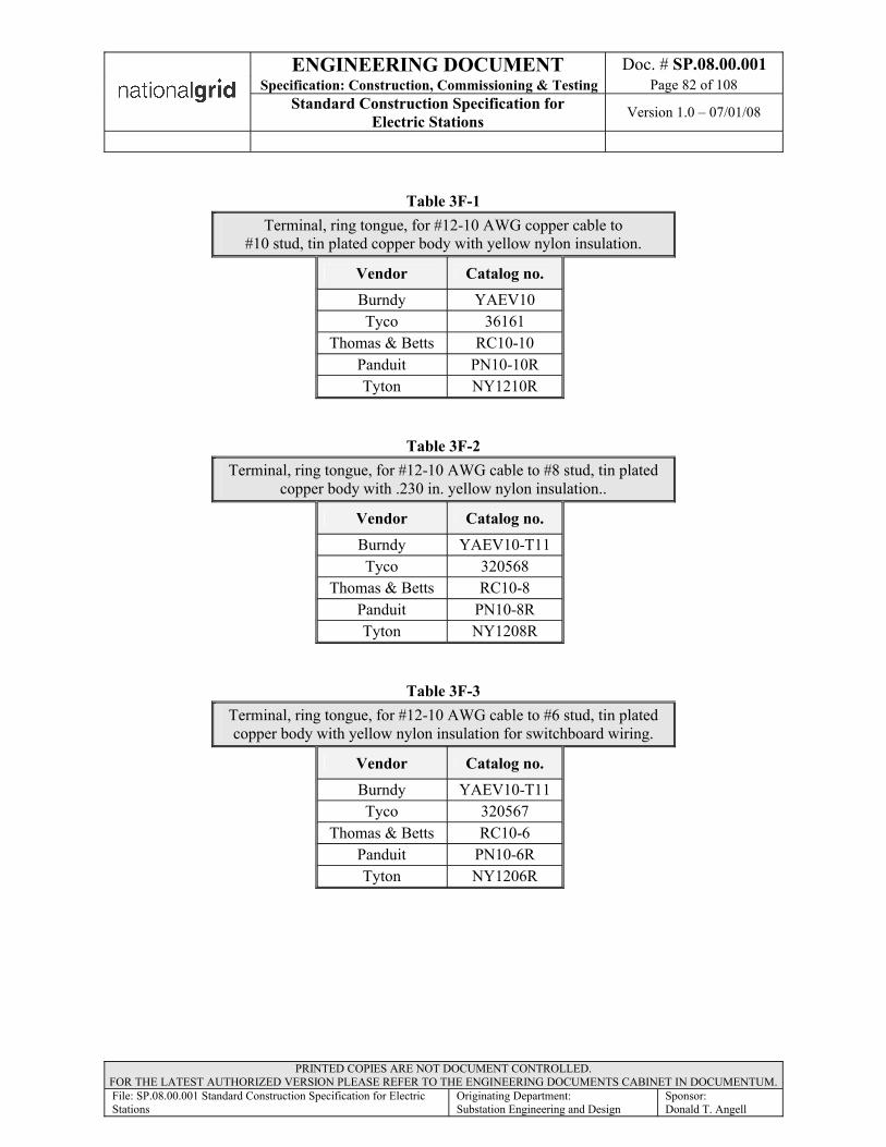
ENGINEERING DOCUMENT Doc. # SP.08.00.001Specification: Construction, Commissioning & Testing Page 82 of 108
Standard Construction Specification for Electric Stations Version 1.0 – 07/01/08
PRINTED COPIES ARE NOT DOCUMENT CONTROLLED. FOR THE LATEST AUTHORIZED VERSION PLEASE REFER TO THE ENGINEERING DOCUMENTS CABINET IN DOCUMENTUM.File: SP.08.00.001 Standard Construction Specification for Electric Stations
Originating Department:Substation Engineering and Design
Sponsor:Donald T. Angell
Table 3F-1Terminal, ring tongue, for #12-10 AWG copper cable to
#10 stud, tin plated copper body with yellow nylon insulation.
Vendor Catalog no.Burndy YAEV10Tyco 36161
Thomas & Betts RC10-10Panduit PN10-10RTyton NY1210R
Table 3F-2Terminal, ring tongue, for #12-10 AWG cable to #8 stud, tin plated
copper body with .230 in. yellow nylon insulation..
Vendor Catalog no.Burndy YAEV10-T11Tyco 320568
Thomas & Betts RC10-8Panduit PN10-8RTyton NY1208R
Table 3F-3Terminal, ring tongue, for #12-10 AWG cable to #6 stud, tin plated copper body with yellow nylon insulation for switchboard wiring.
Vendor Catalog no.Burndy YAEV10-T11Tyco 320567
Thomas & Betts RC10-6Panduit PN10-6RTyton NY1206R

ENGINEERING DOCUMENT Doc. # SP.08.00.001Specification: Construction, Commissioning & Testing Page 83 of 108
Standard Construction Specification for Electric Stations Version 1.0 – 07/01/08
PRINTED COPIES ARE NOT DOCUMENT CONTROLLED. FOR THE LATEST AUTHORIZED VERSION PLEASE REFER TO THE ENGINEERING DOCUMENTS CABINET IN DOCUMENTUM.File: SP.08.00.001 Standard Construction Specification for Electric Stations
Originating Department:Substation Engineering and Design
Sponsor:Donald T. Angell
Table 3F-4Terminal, ring tongue, for #16-14 AWG cable to #10 stud, tin plated
copper body with blue nylon insulation.
Vendor Catalog no.Burndy YAEV14Tyco 36160
Thomas & Betts RB14-10Panduit PN14-10RTyton NY1610R
Table 3F-5Terminal, ring tongue, for #16-14 AWG cable to #8 stud, tin plated
copper body with blue nylon insulation for switchboard wiring.
Vendor Catalog no.Burndy YAEV14Tyco 360627Tyco 8-320627-2
Thomas & Betts RB14-8Panduit PN14-8RTyton NY1608R
Table 3F-6Terminal, ring tongue, for #16-14 AWG cable to #6 stud, tin plated
copper body with blue nylon insulation for switchboard wiring.
Vendor Catalog no.Tyco 360631
Thomas & Betts RB14-6Panduit PN14-6RTyton NY1606R
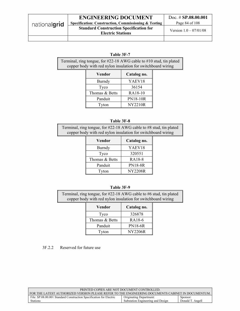
ENGINEERING DOCUMENT Doc. # SP.08.00.001Specification: Construction, Commissioning & Testing Page 84 of 108
Standard Construction Specification for Electric Stations Version 1.0 – 07/01/08
PRINTED COPIES ARE NOT DOCUMENT CONTROLLED. FOR THE LATEST AUTHORIZED VERSION PLEASE REFER TO THE ENGINEERING DOCUMENTS CABINET IN DOCUMENTUM.File: SP.08.00.001 Standard Construction Specification for Electric Stations
Originating Department:Substation Engineering and Design
Sponsor:Donald T. Angell
Table 3F-7Terminal, ring tongue, for #22-18 AWG cable to #10 stud, tin plated
copper body with red nylon insulation for switchboard wiring
Vendor Catalog no.Burndy YAEV18Tyco 36154
Thomas & Betts RA18-10Panduit PN18-10RTyton NY2210R
Table 3F-8Terminal, ring tongue, for #22-18 AWG cable to #8 stud, tin plated
copper body with red nylon insulation for switchboard wiring
Vendor Catalog no.Burndy YAEV18Tyco 320551
Thomas & Betts RA18-8Panduit PN18-8RTyton NY2208R
Table 3F-9Terminal, ring tongue, for #22-18 AWG cable to #6 stud, tin plated
copper body with red nylon insulation for switchboard wiring
Vendor Catalog no.Tyco 326878
Thomas & Betts RA18-6Panduit PN18-6RTyton NY2206R
3F.2.2 Reserved for future use
ENGINEERING DOCUMENT Doc. # SP.08.00.001Specification: Construction, Commissioning & Testing Page 85 of 108
Standard Construction Specification for Electric Stations Version 1.0 – 07/01/08
PRINTED COPIES ARE NOT DOCUMENT CONTROLLED. FOR THE LATEST AUTHORIZED VERSION PLEASE REFER TO THE ENGINEERING DOCUMENTS CABINET IN DOCUMENTUM.File: SP.08.00.001 Standard Construction Specification for Electric Stations
Originating Department:Substation Engineering and Design
Sponsor:Donald T. Angell
3F.2.3 Crimping Tools. Crimping tools used to secure conductors in compression type connectors or terminal lugs shall be those made for that purpose and for the conductor sizes involved. The crimping tools shall accurately crimp the connector barrel and shall accurately crimp the conductor insulation support sleeve where provided. Crimping tools shall be provided with guides to position connectors in the tool, shall be provided with stops to prevent over-crimping, and shall be of a type which prevents the tools from opening until the crimp action is completed. Crimping tools shall be a product of the connector manufacturer or shall be as recommended by the connector manufacturer and acceptable to the Owner for use with the connectors. The Contractor shall establish and maintain a tool certification program to ensure that crimping tools are kept in accurate operating condition.
3F.2.4 Insulating Materials. Insulating materials for 600 volt cable terminal connectors or bolted type splicing connectors shall consist of varnished cambric tape, rubber tape, and vinyl tape. Taping materials shall be as listed below or acceptable equal.
a. Varnished Cambric Tape - 3M Company Irvington 2520b. Rubber Tape - 3M Company Scotch 130Cc. Vinyl Tape - 3M Company Scotch 33+
3F.2.5 Support Grips. Cable support grips shall be either split or closed woven wire type as manufactured by Hubbell Incorporated (Wiring Device–Kellems Division), Milford CT.
3F.2.6 Wire & Conductor Markers. All terminals on terminal blocks provided for termination of external circuits shall be identified by typed black circuit designations acceptable to the Owner on the terminal block strips. All other wiring terminations shall be identified by typing on conductor identification sleeves. A conductor identification sleeve shall be provided on each end of each conductor. Each sleeve shall be marked with the opposite end destination. Conductor identification sleeves shall be not less than 1/2 inch long and shall be as manufactured by the Dura Mark Company, Port Washington, New York or acceptable equal. After inscription of the conductor identification, the marking sleeve shall be covered with a clear plastic or acrylic coating or cover. Conductor identification shall be permanent, unaffected by heat, solvents, or steam, and not easily dislodged. The preferred method is to use Brady heat-stamp sleeves or similar Owner approved equivalent.
3F.2.7 Cable Ties. Lacing materials for field installed cable shall be non-releasing, weather resistant black nylon ties manufactured by Thomas & Betts Company, Elizabeth, New Jersey; Panduit Corp., Tinley Park, Illinois; 3M Company; or acceptable equal.
3F.2.8 Arcproofing Material. Material for arc proofing cable shall be an unsupported intumescent self extinguishing elastomer tape, 3M Company Scotch Brand No.77 or acceptable equal, and a pressure sensitive silicone adhesive backed glass cloth holding tape, 3M Company Scotch Brand No.69, or acceptable equal.

ENGINEERING DOCUMENT Doc. # SP.08.00.001Specification: Construction, Commissioning & Testing Page 86 of 108
Standard Construction Specification for Electric Stations Version 1.0 – 07/01/08
PRINTED COPIES ARE NOT DOCUMENT CONTROLLED. FOR THE LATEST AUTHORIZED VERSION PLEASE REFER TO THE ENGINEERING DOCUMENTS CABINET IN DOCUMENTUM.File: SP.08.00.001 Standard Construction Specification for Electric Stations
Originating Department:Substation Engineering and Design
Sponsor:Donald T. Angell
3F.3 INSTALLATION
Conductor installation shall be in accordance with the cable manufacturer's recommendations and as specified herein.
3F.3.1 Cable Routing. The Contractor shall route all conductors in accordance with the Owner’s conduit and cable schedule and/or drawings and as described herein.
a. Pull all conductors into a raceway at the same time. Use UL listed pulling
lubrications for pulling all cables and larger wires. Petroleum based grease is notacceptable.
b. Install wire in raceway after all mechanical work likely to injure conductors has been completed.
c. The Contractor shall inspect all conduit sections before pulling cable to insure that they are free of foreign materials. The Contractor shall test each conduit by pulling a mandrel through the conduit. The mandrel shall be flexible, about ¼ inch less in diameter than the inside diameter of the conduit and shall be pulled through the conduit followed by a wire brush. If the mandrel encounters opposition, the cause of opposition or scoring must be removed and the conduit re-tested until acceptable to the Owner. A small diameter plastic pulling line, Cartage Group Radiant Poly Line Model 1 ply-110-2 mil or as approved by the Owner, shall be installed during the final test and left in the conduit.
d. Cable shall not be handled when the cable temperature is below the minimum temperature recommended by the manufacturer. If cable heating is required prior to placement, the cable shall be stored in a heated building in accordance with themanufacturer's recommendations for at least 24 hours. The cable shall not beremoved from heated storage until it is ready to be installed that same day.
e. If at any time during the progress of the work the Contractor finds raceways which appear inadequate to accommodate the assigned cable, the Owner shall be notifiedat once and the Contractor shall discontinue any further work on the questionable raceway until advised by the Owner as to how to proceed.
f. Immediately prior to the placement of each cable or cable group, the raceway route to be followed shall be inspected and ascertained to be complete in installation and free of all materials detrimental to the cable or its placement. All cable assigned to a particular duct or conduit shall be grouped and pulled in simultaneously using cable grips and acceptable lubricants.
g. All cable shall be carefully checked both as to size and length before being pulled into conduits or ducts. Cable pulled into the wrong conduit or duct or cut too short to rack, train, and splice as specified herein shall be removed and replaced by and at the expense of the Contractor. Cable removed from one conduit or duct shall not be pulled into another conduit or duct.
ENGINEERING DOCUMENT Doc. # SP.08.00.001Specification: Construction, Commissioning & Testing Page 87 of 108
Standard Construction Specification for Electric Stations Version 1.0 – 07/01/08
PRINTED COPIES ARE NOT DOCUMENT CONTROLLED. FOR THE LATEST AUTHORIZED VERSION PLEASE REFER TO THE ENGINEERING DOCUMENTS CABINET IN DOCUMENTUM.File: SP.08.00.001 Standard Construction Specification for Electric Stations
Originating Department:Substation Engineering and Design
Sponsor:Donald T. Angell
h. Cable in Trays. All cable shall be carefully laid in or pulled through the tray system so that neither the cable nor the trays are damaged. Cable may be laid along the side of the tray system during placement provided it is protected from dirt, water, oil, or other detrimental materials and from mechanical injury. Cable shall be cut sufficiently long to conform to the contour of the trays, with particular attention paid to vertical inside bends. All excessive slack shall be removed from the cable so that it lies parallel to the sides of the trays. Multiple single conductor cable which constitutes a single power circuit shall be grouped together to minimize magnetic influence on other cable in the area. The cable shall be tied to the trays with nylon ties at 10 foot intervals to hold it in place. Cable clamps designed for holding the cable inside the trays shall be installed at all vertical bends.
i. Cable Pulling. Fishing and pulling shall be done with flexible round metal tape, CO2 propelled polyethylene cord, nylon rope, or manila rope. Unless specified otherwise or acceptable to the Owner, cable shall not be pulled in a single pull through two sections of raceway connected by a pull box. Cable shall be pulled out at each pull box to the length required for termination. Prior to re-pulling of the pulled out cable, the cable shall be thoroughly inspected, cleaned, and re-lubricated. Damaged cable shall be removed and replaced by and at the expense of the Contractor. Cable may be pulled in a single pull through two sections of raceway connected by a pull box only if it can be determined by calculation to thesatisfaction of the Owner, that the pulling tension will not exceed the maximum tension allowed by the cable manufacturer.
j. Cable Grips. Factory installed pulling eyes shall be used for pulling cable where they are available. Woven wire cable grips shall be used to pull all single conductor cable 2/0 AWG and larger, where pulling eyes are not available, and all multiconductor cable. Pulling loops shall be used to pull single conductor cable smaller than 2/0 AWG. All sharp points and edges on the hardware attaching the pulling rope to the cable shall be taped to prevent snagging or damaging the raceway. When a cable grip or pulling eye is used for pulling, the area of the cable covered by the grip or seal plus 6 inches shall be cut off and discarded when the pull is completed. When pulling loops are used, the entire loop shall be cut off and discarded when the pull is completed. As soon as the cable is pulled into place, the pulling eyes, cable grips, or pulling loops shall be removed and any cable which was sealed shall be resealed.
k. Swivels. A reliable nonfreezing type of swivel, or swivel connection, shall be inserted between the pulling rope and the cable pulling eye, grip, or loop to prevent twisting under strain.

ENGINEERING DOCUMENT Doc. # SP.08.00.001Specification: Construction, Commissioning & Testing Page 88 of 108
Standard Construction Specification for Electric Stations Version 1.0 – 07/01/08
PRINTED COPIES ARE NOT DOCUMENT CONTROLLED. FOR THE LATEST AUTHORIZED VERSION PLEASE REFER TO THE ENGINEERING DOCUMENTS CABINET IN DOCUMENTUM.File: SP.08.00.001 Standard Construction Specification for Electric Stations
Originating Department:Substation Engineering and Design
Sponsor:Donald T. Angell
l. Feeding Tubes. A 4 inch or larger flexible feeding tube, with a removable nozzle sized to fit the ducts, shall be used in pulling all underground cable. The feeding tube shall be long enough to extend from the duct entrance to the outside of the manhole and shall be so arranged that it will be impossible for the cable to drag across the edge of the manhole ring or any other damaging surface. The bending radius of the tube shall not be less than the minimum bending radius of the cable specified in this section under the article titled Cable Bends.
m. Pulling Lubricants. Only lubricants recommended by the cable manufacturer and acceptable to the Owner shall be used. Lubricants shall be applied liberally and continuously during the pull.
n. Inspection. The Contractor shall carefully inspect the outside of each cable reel and shall remove all protruding nails, fastenings, or other objects which might damage the cable. A thorough visual inspection for flaws, breaks, or abrasions in the cable sheath shall be made as the cable leaves the reel, and the pulling speed shall be slow enough to permit this inspection. Damage to the sheath or finish of the cable shall be sufficient cause for rejecting the cable. Cable damaged in any way during installation shall be replaced by and at the expense of the Contractor.
o. Pulling Tension. The pulling tension of any cable shall not exceed the maximum tension recommended by the cable manufacturer. Pulling mechanisms of both the manual and power types used by the Contractor shall have the rated capacity in tons clearly marked on the mechanism. Whenever the capacity of the pulling mechanism exceeds the recommended pulling tension of the cable as given by the cable manufacturer, a dynamometer shall be used to show the tension on the cable and the indicator shall be constantly watched. If any excessive strain develops, the pulling operation shall be stopped at once and the difficulty determined and corrected.
p. Sidewall Pressure. To avoid insulation damage from excessive sidewall pressure at bends, the pulling tension in pounds at a bend shall not exceed 300 times the radius of the bend in feet.
q. Cable Bends. Tape shielded, flat tape armored, and wire armored cable shall not be bent to a radius of less than 12 times the overall cable diameter. All other cables shall not be bent to a radius of less than eight times the cable diameter.

ENGINEERING DOCUMENT Doc. # SP.08.00.001Specification: Construction, Commissioning & Testing Page 89 of 108
Standard Construction Specification for Electric Stations Version 1.0 – 07/01/08
PRINTED COPIES ARE NOT DOCUMENT CONTROLLED. FOR THE LATEST AUTHORIZED VERSION PLEASE REFER TO THE ENGINEERING DOCUMENTS CABINET IN DOCUMENTUM.File: SP.08.00.001 Standard Construction Specification for Electric Stations
Originating Department:Substation Engineering and Design
Sponsor:Donald T. Angell
r. Supports. All cable supports and securing devices shall have bearing surfaces located parallel to the surfaces of the cable sheath and shall be installed to provide adequate support without deformation of the cable jackets or insulation. Adequate cable end lengths shall be provided and properly placed in junction boxes to avoid longitudinal strains and distorting pressures on the cable at conduit bushings and duct end bells. Final inspection shall be made after all cable is in place and, where supports or raceway fittings deform the cable jacket, additional supports shall be provided as directed by the Owner. Additional cable protection such as a wrapping of light rubber belting, friction tape, or similar material shall be provided where required.
s. Spare Conductors. All spare conductors of a multiconductor cable shall be left at their maximum lengths for possible replacement of any other conductors in the cable. Each spare conductor shall be neatly coiled and then taped to the conductors being used. If the drawings show that the spare conductors are to be terminated, the Contractor shall terminate these conductors.
t. Lacing. Nylon ties shall be used to neatly lace together conductors entering switchboards and similar locations after the conductors have emerged from their supporting raceway and before they are attached to terminals.
u. Cable Identification. The Contractor shall identify the ends of all cables listed in the Conduit & Cable Schedule. Each marker shall bear the number of the cable according to the Conduit & Cable Schedule and the Drawings. At terminations, the Contractor shall identify each conductor of power circuits, each multiconductor cable, and each conductor of circuits consisting of multiple single conductors where the conductors are not otherwise identified. Markers shall be attached where the first individual conductor is routed away from the assembly. Each phase of multi-phase power circuits shall be individually identified.
v. Cable Color Coding. All cables shall be wired to the color coding shown in the Standard Cable Color Coding Spec. CABLCOLR. Single conductor DC power cable shall be wired as white being positive and as black being negative.
3F.3.2 Splices. No splices shall be made in conductors for instrument circuits or control circuits except where required at connections to accessory devices equipped with factory installed pigtails. Protective relay wires from CTs and PTs shall not be spliced. Shields may be spliced where necessary to permit connection to the station ground.Any other proposed splicing must be approved by the Owner’s Engineering Department.
a. Power cable circuits shall not be spliced.
b. Splices shall not be made to utilize short lengths of cable nor shall they be made to provide correct lengths on cable initially cut too short for a particular circuit, unless otherwise approved by the Owner’s Engineering Department.

ENGINEERING DOCUMENT Doc. # SP.08.00.001Specification: Construction, Commissioning & Testing Page 90 of 108
Standard Construction Specification for Electric Stations Version 1.0 – 07/01/08
PRINTED COPIES ARE NOT DOCUMENT CONTROLLED. FOR THE LATEST AUTHORIZED VERSION PLEASE REFER TO THE ENGINEERING DOCUMENTS CABINET IN DOCUMENTUM.File: SP.08.00.001 Standard Construction Specification for Electric Stations
Originating Department:Substation Engineering and Design
Sponsor:Donald T. Angell
c. Splices, joints, and connections shall be made only in pull boxes or junction boxes as indicated on the Drawings. Use solder less pressure connectors with insulating covers for copper wire splices and taps, 8 AWG and smaller. Use split bolt connectors for copper wire tap, 6 AWG and larger. Tape un-insulated conductors and connectors with electrical tape to 150 percent of the insulation value of conductor.
3F.3.3 Terminations. The Contractor shall install cable terminations per the drawings and as specified herein.
a. Make taps and terminations to carry full ampacity of conductors without perceptible temperature rise.
b. Thoroughly clean wires before installing large lugs and connectors.
c. The Contractor shall carefully train cable in place avoiding sharp bends and cut squarely to required length. At points where the conductor and cable insulation will be terminated, terminations shall be made in a neat, workmanlike, and approved manner by a qualified person specialized in this class of work with particular attention being given to higher voltage terminations and shielded conductor terminations. Spare cables shall be trimmed, taped and bundled neatly within the cabinet so their presence will not interfere with connected terminations. They shall be trimmed to a length such that they can be made up and connected to the farthest terminal block within the cabinet.
d. The Contractor shall carefully remove the necessary amount of cable jacket and insulation without damage to the conductor, with a qualified stripping instrument.
e. The Contractor shall install terminals or terminal connectors as required, ensuring a firm metal-to-metal contact. Appropriately sized wire ring terminals shall be used.
f. Control cable terminations shall be made in accordance with the Owner’s connection and interconnection diagrams. All control circuits shall be labeled withindividual wire numbers as described in the labeling section of this document.
g. It is the intent that the Contractor shall terminate all of the cables which he installs, except as otherwise specified by the Owner. Spare cables shall also be labeled as such.
h. Mechanical ground wires shall be green throughout the system. Insulated ground wires may be used provided the ends are properly identified.
i. Where additional protection and support of trimmed conductors is required at terminations, etc.; Raychem heat shrink tubing or equivalent shall be used to cover exposed conductors.
ENGINEERING DOCUMENT Doc. # SP.08.00.001Specification: Construction, Commissioning & Testing Page 91 of 108
Standard Construction Specification for Electric Stations Version 1.0 – 07/01/08
PRINTED COPIES ARE NOT DOCUMENT CONTROLLED. FOR THE LATEST AUTHORIZED VERSION PLEASE REFER TO THE ENGINEERING DOCUMENTS CABINET IN DOCUMENTUM.File: SP.08.00.001 Standard Construction Specification for Electric Stations
Originating Department:Substation Engineering and Design
Sponsor:Donald T. Angell
j. Insulation of 600 Volt Cable Connections.
Each connection of cable to an insulated conductor (whether cable, bus, or equipment bushing) shall be insulated. The insulation shall cover all exposed surfaces of the conductors; the insulation voltage level of the completed termination shall be not less than the insulation voltage level of the connected conductors. Where connections of cable rated 600 volts or less require insulation, all exposed conductor and connector surfaces shall be covered and taped with:
• One half-lapped layer of varnished cambric tape• A minimum of three half-lapped layers of rubber tape, elongated not more
than 20 percent; applied over the varnished cambric tape• A minimum of three half-lapped layers of vinyl tape applied over the rubber
tape. (The vinyl tape shall extend a minimum of two cable diameters overthe cable jacket and a similar distance over the insulation of the conductor to which the cable is connected.)
3F.3.4 Conductor Tests.
All insulated conductors shall be electrically tested after placement. All circuits, including lighting circuits, shall be tested with the circuit complete except for connections to equipment. All splices, stress cones on shielded cable, and terminal connector attachments shall be complete prior to testing. In addition to the tests performed after cable placement is complete, continuity tests and insulation tests shall be performed on all supervisory and communication cable before and after each splice is made. Any circuit failing to test satisfactorily shall be replaced or repaired and then retested.
Before any power cable terminal connections are made, conductors shall be rung out. Connections shall be made according to wiring diagrams. Polarity or phasing shall be checked before final connections are made, and corrections of polarity, phasing or rotation shall be made without additional cost to the Owner.
a. Continuity Tests. All insulated conductors shall be tested for continuity. Continuity tests shall include all tests necessary to confirm that each conductor is continuous throughout its entire length.
b. Identification Tests. All insulated conductors shall be tested for conductor identification. Identification tests shall include all tests necessary to confirm that the conductor being investigated originates and terminates at the locations designated in the Conduit & Cable Schedule or indicated on the Drawings.
ENGINEERING DOCUMENT Doc. # SP.08.00.001Specification: Construction, Commissioning & Testing Page 92 of 108
Standard Construction Specification for Electric Stations Version 1.0 – 07/01/08
PRINTED COPIES ARE NOT DOCUMENT CONTROLLED. FOR THE LATEST AUTHORIZED VERSION PLEASE REFER TO THE ENGINEERING DOCUMENTS CABINET IN DOCUMENTUM.File: SP.08.00.001 Standard Construction Specification for Electric Stations
Originating Department:Substation Engineering and Design
Sponsor:Donald T. Angell
c. Cable Rated Below 5000 Volts. All insulated conductors, except supervisory and communication cable, rated less than 5000 volts shall be tested for resistance from ground provided by the insulation with a 1000 volt megger or an equivalent testing device, in accordance with the manufacturer’s test requirements. These tests shall be done prior to making final connections. Insulation resistance measurements shall be made between each conductor and ground and between each conductor and all other conductors of the same cable. Minimum acceptable resistance values shall be approximately 500 megohms. This includes all CT Cable Conductors.
d. Cable Rated Above 5000 Volts. For cables installed above 5000 volts, the tester shall megger check the conductorsin accordance with the Owner’s Distribution Underground Standards, EOPUG004, latest revision.
e. Supervisory and Communication Cable. All insulated conductors of supervisory and communication cable shall be tested for resistance with a 500 volt megger or an equivalent testing device. Insulation resistance measurements shall be made between each conductor and the cable shielding tape and between the two conductors in each pair. Minimum acceptable resistance values shall be 500 megohms divided by the actual cable length in miles.
f. CT Cable Conductors. Contractor shall test all the CT cable conductors with a Megger insulation testing instrument prior to making final connections to the equipment. In the event the insulation value is unacceptable, corrective measures shall be taken and the test shall be repeated. Test shall be performed, as applicable, in accordance with Clause 11 of IEEE 525 in conjunction with the cable manufacturer’s recommendations.
3F.3.5 Codes and Standards. The Contractor shall conform to the following minimum applicable codes and standards for Section 3F.
a. NEMA WC 3 – Rubber-Insulated Wire and Cable for the Transmission and Distribution of Electrical Energy.
b. NEMA WC 5 – Thermoplastic-Insulated Wire and Cable for the Transmission and Distribution of Electrical Energy.
c. Cable Pulling and Testing Requirements. IEEE Std. 525 Clauses 10 &11.
d. Electric Station Standards Section 10.0 Conductors and the Substation Field IssueMaterials List
e. NFPA-70, "2005 National Electrical Code" or latest.
ENGINEERING DOCUMENT Doc. # SP.08.00.001Specification: Construction, Commissioning & Testing Page 93 of 108
Standard Construction Specification for Electric Stations Version 1.0 – 07/01/08
PRINTED COPIES ARE NOT DOCUMENT CONTROLLED. FOR THE LATEST AUTHORIZED VERSION PLEASE REFER TO THE ENGINEERING DOCUMENTS CABINET IN DOCUMENTUM.File: SP.08.00.001 Standard Construction Specification for Electric Stations
Originating Department:Substation Engineering and Design
Sponsor:Donald T. Angell
3F.3.6 CABLE TYPES. All cable materials supplied by the Contractor shall meet or exceedthe minimum requirements listed in the applicable cable specifications included in the Substation Field Issue. Any exceptions to these minimum requirements shall be approved by the Owner’s Engineering Department in advance, so that the overall installation schedule will not be impacted. The Contractor should be aware that these cables may be considered special order cables and should plan in advance for long lead times.
Section 3G (265100) (265600) - INTERIOR/EXTERIOR LIGHTING
3G.1 GENERAL
The Contractor shall install all lighting materials and equipment as indicated on the Drawings and specified herein. The Contractor shall furnish all lighting materials, except as specified in the Material Lists as being furnished by the Owner, in quantities sufficient for a complete installation.
3G.2 INSTALLATION
Lighting equipment, material, and wiring devices shall be installed according to the Drawings and as specified herein.
3G.2.1 Fixtures. Each complete fixture shall be secured to its support assembly. This work includes but is not limited to all special drilling, assembling, disassembling, reassembling, and wiring. Fixture maintenance shall be continuous until the date of commercial operation. All fixtures shall be cleaned immediately prior to the Con-tractor leaving the job site.
a. Location. Fixture locations indicated on the Drawings are approximate and shall be coordinated with other work in the same area to prevent interference between lighting fixtures and other equipment. Any fixture shall be relocated if, after installation, it is found to interfere with other equipment or is so located to prevent its practical and intended use. No fixture shall be located such that it prevents the full use of any access way beneath a removable grating or slab.
b. Alignment. Fixtures installed in rows shall be carefully aligned vertically and horizontally.
3G.2.2 Wiring Device Mounting Heights. Unless otherwise indicated on the Drawings, receptacles shall be mounted 36 inches above finished grade (or finished floor) and switches shall be mounted 48 inches above finished grade (or finished floor).
3G.2.3 Lighting Conductors. The installation of lighting conductors shall conform to the applicable installation procedures specified elsewhere herein for power and control conductors.
a. At least 6 inches of free lighting conductor shall be left at each outlet except where the conductor loops through an outlet without splice or connection.

ENGINEERING DOCUMENT Doc. # SP.08.00.001Specification: Construction, Commissioning & Testing Page 94 of 108
Standard Construction Specification for Electric Stations Version 1.0 – 07/01/08
PRINTED COPIES ARE NOT DOCUMENT CONTROLLED. FOR THE LATEST AUTHORIZED VERSION PLEASE REFER TO THE ENGINEERING DOCUMENTS CABINET IN DOCUMENTUM.File: SP.08.00.001 Standard Construction Specification for Electric Stations
Originating Department:Substation Engineering and Design
Sponsor:Donald T. Angell
b. General purpose cable shall be used to connect all incandescent lighting fixtures. The general purpose cable shall be installed in the circuit between the lighting circuit outlet box and the fixture terminal.
c. Wires to be spliced shall use solderless pressure connectors with insulating covers.
3G.2.4 Exterior Area Lighting Installation. Outdoor area and outdoor equipment lighting shall be installed on structures as indicated on the Drawings and as specified herein.
a. For outdoor area lighting, the structures shall be installed before lighting fixtures are mounted on the structure. Cable connections for outdoor pole mounted fixtures shall be completed in the handhole located near the base of the light support structure.
b. For outdoor equipment, uplighting lighting fixtures shall be mounted after the structures have been fully erected. Cable connections shall be completed in the junction boxes located on the structures.
c. Conductors. Underground conductors of the outdoor area lighting and equipment uplighting systems shall be comprised of jacketed aluminum sheathed multiple conductor cable, unless otherwise noted on the drawings. Above ground conductors of the outdoor area lighting system will be single conductor cable. Above ground conductors of the outdoor equipment uplighting system will be comprised of aluminum sheathed multiple conductor cable. Conductors shall be routed as indicated on the Drawings.
d. Grounding. All outdoor lighting equipment shall be grounded in accordance with the Drawings and as specified elsewhere in this Specification
Section 3H (260700) - POWER CIRCUIT BREAKERS
3H.1 INSTALLATION
3H.1.1 This section is applicable for all outdoor free standing circuit breaker installations. This section may be modified or omitted depending on the summary of work descriptions in the Substation Field Issue.
3H.1.2 The Contractor shall provide all labor, materials, tools, equipment, accessories, and services necessary to unload and install each circuit breaker assembly in its permanent location, as shown on the contract drawings and described in these specifications.
3H.1.3 The Contractor shall provide placement and anchoring (if necessary) of each circuit breaker on its foundation.
3H.1.4 The Contractor shall remove all shipping members and protective coverings.

ENGINEERING DOCUMENT Doc. # SP.08.00.001Specification: Construction, Commissioning & Testing Page 95 of 108
Standard Construction Specification for Electric Stations Version 1.0 – 07/01/08
PRINTED COPIES ARE NOT DOCUMENT CONTROLLED. FOR THE LATEST AUTHORIZED VERSION PLEASE REFER TO THE ENGINEERING DOCUMENTS CABINET IN DOCUMENTUM.File: SP.08.00.001 Standard Construction Specification for Electric Stations
Originating Department:Substation Engineering and Design
Sponsor:Donald T. Angell
3H.1.5 The Contractor shall make the primary conductor terminations to the bushings per thecable manufacturer’s and Owner’s instructions.
3H.1.6 The Contractor shall ensure connecting circuit breaker to the station grounding system.
3H.2 MATERIALS DELIVERY, STORAGE AND RIGGING
3H.2.1 The Contractor shall store materials properly to prevent theft, damage, deterioration and inclusion of foreign matter. Packaged materials delivered must be kept in the original shipping cartons to avoid loss of parts.
3H.2.2 The Contractor shall handle the circuit breaker by rolling or lifting using appropriate rigging as required.
3H.2.3 For SF6 gas circuit breakers, the Contractor shall properly fill the circuit breakers with SF6 gas in accordance with the manufacturer’s instructions.
3H.2.4 The Contractor is responsible for the full installation and setup of the circuit breakerincluding full compliance with the manufacturer’s recommendations.. The Owner willdo the functional testing and commissioning, unless otherwise called out in the Substation Field Issue.
3H.3 CODES AND STANDARDS
The Contractor shall comply with the provisions of the National Electric Code (NEC) for the breakers auxiliary wiring except where more stringent requirements are shown or specified.
3H.4 PRODUCTS GENERAL
The Owner will supply the circuit breaker(s) to install. The Contractor shall furnish all miscellaneous material not previously installed by prior work and not provided by the Owner as indicated on Bill of Materials List to complete the circuit breaker installation.
3H.5 INSTALLATION GENERAL
3H.5.1 The Contractor shall install the circuit breaker using the appropriate rigging as per the manufacturer’s recommendations for the locations shown on the Owner’s drawings. The Contractor shall provide all rigging required. The circuit breaker dimensions and weight are shown on the Owner’s provided drawings.
3H.5.2 Each circuit breaker shall be placed on it’s foundation in accordance with the manufacturer’s recommendations.
3H.5.3 The Contractor shall complete all power cable terminations with the correct phasing arrangements to the high and low side bushings.

ENGINEERING DOCUMENT Doc. # SP.08.00.001Specification: Construction, Commissioning & Testing Page 96 of 108
Standard Construction Specification for Electric Stations Version 1.0 – 07/01/08
PRINTED COPIES ARE NOT DOCUMENT CONTROLLED. FOR THE LATEST AUTHORIZED VERSION PLEASE REFER TO THE ENGINEERING DOCUMENTS CABINET IN DOCUMENTUM.File: SP.08.00.001 Standard Construction Specification for Electric Stations
Originating Department:Substation Engineering and Design
Sponsor:Donald T. Angell
3H.5.4 The Contractor shall perform any degassing of SF6 circuit breakers, gas top-ups for circuit breakers, and gas startup measures; in addition to what is called out in the work summary.
3H.6 CIRCUIT BREAKER REMOVALS
Where indicated in the Substation Field Issue, the Contractor shall remove all existing circuit breakers and accessories from their foundations and dispose of them as directed by the work summary. Any oil handling requirements shall be carried out as indicated in the work summary and shall be in strict compliance with all environmental rules and regulations that apply.
Section 3I (261200) - POWER TRANSFORMERS
3I.1 INSTALLATION
3I.1.1 This section is applicable to power transformers. This section may be modified and/or omitted depending on the summary of work descriptions. In some cases the transformer supplier will perform the installation of the transformer. In these cases this section may not apply.
3I.1.2 The Contractor shall provide all labor, materials, tools, equipment, accessories, and services necessary to unload and install the power transformer(s) assemblies in their permanent locations as shown on the contract drawings and described in these specifications.
3I.1.3 The Contractor shall remove of all shipping members and protective coverings.
3I.1.4 The Contractor shall provide placement and anchoring of the power transformer(s) onthe foundation(s).
3I.1.5 The Contractor shall make all power cable connections per the cable manufacturer’s and the Owner’s instructions. The Contractor shall ensure the phasing arrangementsare correct.
3I.1.6 The Contractor shall connect the power transformer(s) to the station grounding system, as applicable.
3I.2 MATERIALS DELIVERY, STORAGE AND RIGGING:
3I.2.1 The Contractor shall be responsible for transporting the transformer(s) from their storage locations to the jobsite. The Contractor shall coordinate arrival at this storage facility for pickup with the Owner’s personnel ahead of time by communicating this through the Construction Supervisor. The Contractor should inspect the major electrical equipment at the storage facility for any damage prior to moving it to the jobsite and should inform the Owner of any defects found prior to starting the moving procedure.
ENGINEERING DOCUMENT Doc. # SP.08.00.001Specification: Construction, Commissioning & Testing Page 97 of 108
Standard Construction Specification for Electric Stations Version 1.0 – 07/01/08
PRINTED COPIES ARE NOT DOCUMENT CONTROLLED. FOR THE LATEST AUTHORIZED VERSION PLEASE REFER TO THE ENGINEERING DOCUMENTS CABINET IN DOCUMENTUM.File: SP.08.00.001 Standard Construction Specification for Electric Stations
Originating Department:Substation Engineering and Design
Sponsor:Donald T. Angell
3I.2.2 The Contractor shall store all materials properly to prevent theft, damage, deterioration and inclusion of foreign matter. Packaged materials delivered must be kept in the original shipping cartons to avoid loss of parts.
3I.2.3 The Contractor shall handle the power transformer(s) by rolling or lifting using appropriate rigging as required.
3I.2.4 The Contractor shall refer to the summary of work to determine if transformer oil filling is necessary.
3I.2.5 The Contractor is responsible for fully dressing out the transformer(s). The Owner will perform the functional testing and commissioning of the transformer(s).
3I.3 CODES AND STANDARDS
The Contractor shall comply with the provisions of the National Electric Code (NEC), as a minimum, for all auxiliary wiring to the transformer, except where more stringent requirements are shown or specified.
3I.4 INSTALLATION MATERIALS
The Owner will supply and provide the transformer(s) to install, unless the contract calls out for something different. The Contractor shall furnish all other miscellaneous material not previously installed by prior work and not provided by the Owner as indicated on the Bill of Materials List.
3I.5 INSTALLATION OF TRANSFORMER PADS
If applicable in the summary of work, the Contractor shall furnish and install a concrete pad in accordancewith the Owner’s structural drawings and the Owner’s structural requirements specified within.
3I.6 INSTALLATION OF TRANSFORMERS
3I.6.1 The Contractor shall install the transformer(s) using the appropriate rigging required in the locations shown on the Owner’s drawings. The Contractor shall provide all rigging required. The transformer dimensions and weight are shown on the Owner’s provided drawings.
3I.6.2 Each power transformer shall be placed on it’s foundation in accordance with the manufacturer’s recommendations.
3I.6.3 All power cable terminations shall be completed with the correct phasing connections to the high and low side bushings.
ENGINEERING DOCUMENT Doc. # SP.08.00.001Specification: Construction, Commissioning & Testing Page 98 of 108
Standard Construction Specification for Electric Stations Version 1.0 – 07/01/08
PRINTED COPIES ARE NOT DOCUMENT CONTROLLED. FOR THE LATEST AUTHORIZED VERSION PLEASE REFER TO THE ENGINEERING DOCUMENTS CABINET IN DOCUMENTUM.File: SP.08.00.001 Standard Construction Specification for Electric Stations
Originating Department:Substation Engineering and Design
Sponsor:Donald T. Angell
3I.1.6 Transformer Testing:
a. The Contractor shall do a point to point wire check of the auxiliary control and relaywiring per the drawings and shall verify by continuity or otherwise that all connections are correct, prior to completing the installation of the transformer(s). The Owner will functionally test and commission the transformer(s).
3I.7 TRANSFORMER REMOVALS
Where indicated, the Contractor shall remove all existing transformers and accessories from their foundations and dispose of them as directed by the work summary. Any oil handling requirements shall be carried out as indicated in the work summary and shall be in strict compliance with all environmental rules and regulations that apply.
Section 3J (260525) - MEDIUM VOLTAGE SWITCHGEAR
3J.1 INSTALLATION
3J.1.1 This section is applicable for indoor and outdoor medium voltage switchgear installations, only. This section may be modified or omitted depending on the summary of work descriptions.
3J.1.2 The Contractor shall provide all labor, materials, tools, equipment, accessories, and services necessary to unload and install the switchgear assemblies in their permanent locations as shown on the contract drawings and described in these specifications.
3J.1.3 The Contractor shall removal of all shipping members and protective coverings.
3J.1.4 The Contractor is responsible for the placement and anchoring of the switchgear on its foundation.
3J.1.5 The Contractor shall make all bus connections between the shipping sections per the manufacturer’s instructions.
3J.1.6 The Contractor shall reconnect all the control wires and ground connections between shipping sections per manufacturer’s instructions, if the sections were shipped separated.
3J.1.7 The Contractor shall make all power cable connections per the switchgear manufacturer’s and owner’s instructions.
3J.1.8 The Contractor shall reconnect the ground bus between the shipping sections and connect the switchgear to the station grounding system.
ENGINEERING DOCUMENT Doc. # SP.08.00.001Specification: Construction, Commissioning & Testing Page 99 of 108
Standard Construction Specification for Electric Stations Version 1.0 – 07/01/08
PRINTED COPIES ARE NOT DOCUMENT CONTROLLED. FOR THE LATEST AUTHORIZED VERSION PLEASE REFER TO THE ENGINEERING DOCUMENTS CABINET IN DOCUMENTUM.File: SP.08.00.001 Standard Construction Specification for Electric Stations
Originating Department:Substation Engineering and Design
Sponsor:Donald T. Angell
3J.2 MATERIALS DELIVERY, STORAGE AND RIGGING
3J.2.1 The Contractor shall store materials properly to prevent damage, deterioration and inclusion of foreign matter. Packaged materials delivered must be kept in the original shipping cartons to avoid loss of parts.
3J.2.2 The Contractor shall handle the switchgear by rolling or lifting in accordance to the manufacturer’s recommendations.
3J.3 CODES AND STANDARDS
3J.3.1 The Contractor shall comply with the provisions of the following codes, specifications and standards listed within, except where more stringent requirements are shown or specified.
• National Electric Code latest edition, NFPA 70• Clause 9 of IEEE Standards for metal enclosed low-voltage power circuit breakers
switchgear C37.20.1.• Owner’s power cable description (22-UC16), and power cable installation cabinet
(7-501-7-506).
3J.4 INSTALLATION GENERAL
3J.4.1 The handling of the switchgear assemblies should be done either by rolling or lifting, using a spreader bar in accordance with the manufacturer’s and C37.20.1 recommendations. All rigging shall be supplied by the Contractor.
3J.4.2 The switchgear shall be assembled on it’s foundation in accordance with the manufacturer’s and IEEE C37.20.1 recommendations. The switchgear dimensions and weight are shown on the drawings.
3J.4.3 Switchgear sections shall be attached to the floor as specified on the drawings, leveled and aligned, and mechanical connections between panel shipping sections shall be completed, as applicable.
3J.4.4 The Owner will do the final functional testing and commissioning of the switchgear after final protective relay testing is complete.
3J.4.5 The Contractor shall ensure that all breakers and relays shall be installed and made ready for the pre-operation check.
3J.4.6 The Contractor shall ensure that all power cables terminations are completed with thecorrect phasing arrangement.
3J.4.7 The Contractor shall ensure that the grounding terminations are consistent with the Owner’s grounding practices throughout the station for power equipment in this voltage classification.

ENGINEERING DOCUMENT Doc. # SP.08.00.001Specification: Construction, Commissioning & Testing Page 100 of 108
Standard Construction Specification for Electric Stations Version 1.0 – 07/01/08
PRINTED COPIES ARE NOT DOCUMENT CONTROLLED. FOR THE LATEST AUTHORIZED VERSION PLEASE REFER TO THE ENGINEERING DOCUMENTS CABINET IN DOCUMENTUM.File: SP.08.00.001 Standard Construction Specification for Electric Stations
Originating Department:Substation Engineering and Design
Sponsor:Donald T. Angell
3J.4.8 The Contractor shall ensure that after installation, any remaining shipping protection shall be removed and the switchgear shall be checked to ensure that they are in good condition and to discover any hidden damage to finish, instruments, or equipment. All protective relays, instruments, meters and other devices shall be checked for physical damage.
3J.4.9 Particular care shall be used in the installation of switchgear to ensure that support, bracing, and hold down details are properly installed, with bolts and fasteners tightened to the specified vendor’s torque values.
Section 3K (260000) - BATTERY AND BATTERY CHARGERS
3K.1 GENERAL
Battery cells are not to be stored for more than the time period recommended by the manufacturer without applying a charge to the battery. In all cases, a period of 3 months storage of the battery is allowable between charges if the cells are stored in a clean, dry, cool location without exposure to extremely low ambient temperatures or localized sources of heat.
No battery installation shall be initiated until appropriate permanently installed or portable eyewash stations are available and operational.
After the eyewash station is installed and operational, the Contractor shall then immediately install and connect the battery and battery charger and prepare them for operation. A temporary power supply shallbe connected to the battery charger and shall be maintained in service until permanent power supplies are installed and ready for continuous service. The source for the temporary power supply shall be as selected by the Owner as being the most reliable. The Contractor shall check with the Owner should a temporary portable battery trailer be required to facilitate the installation/replacement of the existing batteries and charger.
3K.1.1 Assembly. The assembly of the battery and battery rack shall be in accordance with the manufacturer's recommendations and assembly instructions.
a. The individual cells shall be lifted onto the rack using the lifting equipment recommended by the battery manufacturer. Cells shall be lifted by the bottom of the case and not by the cell posts. Cells shall be placed on the designated racks and checked for positive to negative connections throughout the battery prior to theinstallation of inter-cell connectors.
ENGINEERING DOCUMENT Doc. # SP.08.00.001Specification: Construction, Commissioning & Testing Page 101 of 108
Standard Construction Specification for Electric Stations Version 1.0 – 07/01/08
PRINTED COPIES ARE NOT DOCUMENT CONTROLLED. FOR THE LATEST AUTHORIZED VERSION PLEASE REFER TO THE ENGINEERING DOCUMENTS CABINET IN DOCUMENTUM.File: SP.08.00.001 Standard Construction Specification for Electric Stations
Originating Department:Substation Engineering and Design
Sponsor:Donald T. Angell
b. Prior to installing inter-cell connectors, the Contractor shall inspect all terminal posts and connecting hardware. Any area showing evidence of corrosion, dirt, or acid shall be cleaned by rubbing gently with a brass suede brush or fine emery paper, exercising care to prevent removal of lead plating. A thin film of corrosion inhibiting grease shall be applied to all contact surfaces. Inter-cell connections shall be completed with connectors and associated hardware supplied by the battery manufacturer. Where more than one inter-cell connector per cell post is required, the connectors shall be mounted on opposite sides of the post for maximum surface contact. Both ends of the connection bolts shall be tightened to the manufacturers recommended torque values.
c. All cell covers and containers shall be cleaned. A water moistened clean wiper shall be used for the removal of dust and dirt. A bicarbonate of soda and water moistened wiper shall be used for cleanup of electrolyte spillage. All wipers used shall be free of oil distillates. Explosion resistant vent plugs shall be installed where provided. Individual cell numbers in sequence with No. 1 at the positive (+) end of the battery shall be applied for permanent identification.
d. The Contractor shall measure the voltage of the battery to ensure that individual cells are connected correctly. If the measured voltage is less than approximately the number of cells multiplied by the measured voltage of one cell, the individual cell polarities shall be rechecked.
e. The Contractor shall measure and record inter-cell connection resistance. Any con-nection with a resistance measurement exceeding 10 per cent above the average shall be remade and re-measured.
f. Final connections from the battery to the charger and dc system shall be installed after assembly of the battery has been completed.
g. After the battery assembly is complete to the stage of inter-cell connections, the Contractor shall protect the battery from construction dirt and debris.
3K.1.2 Maintenance Inspections and Testing. All applicable Substation Maintenance Procedures (SMP) for acceptance testing of chargers and batteries installed shall be followed.
Refer to the following SMP for inspection and acceptance procedures.§ SMP406.03.2 Battery Charger Procedure§ SMP406.01.2 Lead Acid Battery Procedure§ SMP406.02.2 Nickel-Cadmium Battery Procedure

ENGINEERING DOCUMENT Doc. # SP.08.00.001Specification: Construction, Commissioning & Testing Page 102 of 108
Standard Construction Specification for Electric Stations Version 1.0 – 07/01/08
PRINTED COPIES ARE NOT DOCUMENT CONTROLLED. FOR THE LATEST AUTHORIZED VERSION PLEASE REFER TO THE ENGINEERING DOCUMENTS CABINET IN DOCUMENTUM.File: SP.08.00.001 Standard Construction Specification for Electric Stations
Originating Department:Substation Engineering and Design
Sponsor:Donald T. Angell
3K.1.3 Records and Documentation. All applicable Battery and Charger Inspection Cards shall be completely filled out to document acceptance testing performed and provided to the Owner.
§ SMP406.03.3 Battery Charger Inspection Card§ SMP406.01.3 Lead Acid Battery Inspection Card§ SMP406.02.3 Nickel-Cadmium Battery Inspection Card
Section 3L (260000) – DISCONNECT SWITCHES
3L.1 General Description
3L.1.1 Provide all labor, materials, tools, equipment, accessories, and services necessary to unload and install the specified disconnect switches in their permanent location per the contract drawings and as described in this specification.
3L.1.2 The work of this section includes but is not limited to the following principal items:
a. Removal of all shipping members and protective covering.
b. Mounting of disconnect switches on the structures as indicated on the Owner’sdrawings and per the manufacturer’s installation instructions.
c. Terminating the line and load end of the cable and cable connections per Owner’s instructions. Ensuring the phase connections are correct.
d. If the disconnect switch contains a motor operator, the Contractor shall be responsible for installing the motor operator, the motor operator boxes, all linkages, and all accessories required for the complete electrical operation of the disconnect switch.
e. The Contractor shall install, test, and or commission the disconnect switches in accordance with the requirements in the applicable disconnect switch SMS and SMP standards and procedures listed in the Substation Field Issue.
3L.2 Materials Delivery, Storage, and Rigging
3L.2.1 Store materials properly to prevent theft, damage, deterioration and inclusion of foreign matter. Packaged materials delivered must be kept in the original shipping cartons to avoid loss of parts.
3L.2.2 Handle the disconnect switches using the proper handling equipment for the job in accordance with the manufacturer’s recommendations.
ENGINEERING DOCUMENT Doc. # SP.08.00.001Specification: Construction, Commissioning & Testing Page 103 of 108
Standard Construction Specification for Electric Stations Version 1.0 – 07/01/08
PRINTED COPIES ARE NOT DOCUMENT CONTROLLED. FOR THE LATEST AUTHORIZED VERSION PLEASE REFER TO THE ENGINEERING DOCUMENTS CABINET IN DOCUMENTUM.File: SP.08.00.001 Standard Construction Specification for Electric Stations
Originating Department:Substation Engineering and Design
Sponsor:Donald T. Angell
3L.3 Quality Assurance
3L.3.1 Codes and Standards
a. Comply with the provisions of all applicable IEEE standards and ANSI codes, unless otherwise specified within.
3L.4 Procurement
3L.4.1 Generally, the Owner will procure and supply the disconnect switches. However, this will generally be called out on the Bill of Materials for the job. The Contractor shall furnish all miscellaneous material that may not be included on the Bill of Materials to complete the disconnect switch installation.
3L.5 Transportation Requirements
3L.5.1 Unless otherwise specified, The Contractor shall be responsible for transporting the disconnect switches their storage facility to the jobsite. The Contractor shall coordinate arrival at this storage facility for pickup with Owner’s personnel ahead of time by communicating this through the Construction Supervisor. The Contractor should inspect the disconnects at the storage facility for any damage prior to moving it to the jobsite and shall inform the Owner of any defects found prior to starting the moving procedure.
3L.6 Installation
3L.6.1 The Contractor shall install the disconnect switches in accordance with the approved Owner’s drawings, this specification, and the manufacturer’s installation instructions. Any rigging required shall be supplied by the Contractor.
3L.7 Testing
3L.7.1 The Contractor shall supply testing and commissioning support if requested by the Owner. Refer to the scope of work in Substation Field Issue.
ENGINEERING DOCUMENT Doc. # SP.08.00.001Specification: Construction, Commissioning & Testing Page 104 of 108
Standard Construction Specification for Electric Stations Version 1.0 – 07/01/08
PRINTED COPIES ARE NOT DOCUMENT CONTROLLED. FOR THE LATEST AUTHORIZED VERSION PLEASE REFER TO THE ENGINEERING DOCUMENTS CABINET IN DOCUMENTUM.File: SP.08.00.001 Standard Construction Specification for Electric Stations
Originating Department:Substation Engineering and Design
Sponsor:Donald T. Angell
Section 3M (265000) - TESTING AND COMMISSIONING
3M.1 GENERAL
Generally, the Owner will perform all final functional tests and commissioning, unless otherwise directedin the summary of work section. The Contractor shall provide all Owner requested support and assistance so that the Owner may fully complete this testing and commissioning. All installation deficiencies detected by the Owner prior to, during, or after the final testing shall be corrected by the Contractor at theContractor’s expense. The individuals performing the final testing and commissioning, whether employed by the Owner, or by the Contractor, shall follow the “Substation Commissioning and Energization” procedure SMP480.01.2. This procedure will contain all references to the required SMS and SMP standards & procedures, including the cards required to be filled out for the testing and energization phase of the project. All questions regarding the applicability of these standards and procedures, and how they are to be used, shall be directed to the Construction Supervisor for the project.

ENGINEERING DOCUMENT Doc. # SP.08.00.001Specification: Construction, Commissioning & Testing Page 105 of 108
Standard Construction Specification for Electric Stations Version 1.0 – 07/01/08
PRINTED COPIES ARE NOT DOCUMENT CONTROLLED. FOR THE LATEST AUTHORIZED VERSION PLEASE REFER TO THE ENGINEERING DOCUMENTS CABINET IN DOCUMENTUM.File: SP.08.00.001 Standard Construction Specification for Electric Stations
Originating Department:Substation Engineering and Design
Sponsor:Donald T. Angell
DIVISION 4 - UNDERGROUND CONSTRUCTION
Section 4A (260000) - CONTRACTOR FURNISHED MATERIALS
4A.1 GENERAL
The Contractor shall furnish all equipment and materials, except those specified herein to be furnished by the Owner or other contractors, as necessary to make a complete operational installation as shown on the Drawings and this Specification. Contractor shall be responsible for determining the quantities of material required. The content of this Specification does not necessarily cover all design details and features. The right is reserved to require modifications of construction details or operational features which may not have been discussed in this Specification and which, in the estimation of the Owner, are substandard or undesirable.
4A.1.1 ENGINEERING DATA. The Contractor shall submit drawings to the Owner for acceptance on all major items of material it is required to furnish by this Specification. The Contractor shall submit drawings which adequately indicate the general arrangement of major items of material, principles of operation, sizes, general appearance, and materials of construction.
4A.1.2 CORRECTION OF MANUFACTURING ERRORS. The materials shall be complete in all respects within the limits herein outlined as determined by the Owner. All manufacturing errors or omissions required to be corrected in the field shall be done by the Contractor at his expense, or if done by the Owner, the cost of the same shall be deducted from the contract price.
4A.1.3 MATERIAL LISTS. The Contractor shall furnish all the items labeled or noted as “By Field” on the drawings and Material Lists contained in the Substation Field Issue.
4A.2 INSTALLATION
The Contractor shall install all materials in a neat and workmanlike manner. All work shall be in accordance with the best practices of the electrical construction industry. The completed installation shall provide a minimum of hazard to personnel and shall not interfere with the use, as intended, of the area in which they are installed.
Section 4B (260000) - OWNER FURNISHED MATERIALS
4B.1 GENERAL
Owner-furnished equipment and materials are identified in the Substation Field Issue. Delivery dates and estimated weights for major pieces of Owner-furnished electrical equipment and materials are also included in the Substation Field Issue. All other material and equipment not supplied by the Owner shall be supplied by the Contractor.

ENGINEERING DOCUMENT Doc. # SP.08.00.001Specification: Construction, Commissioning & Testing Page 106 of 108
Standard Construction Specification for Electric Stations Version 1.0 – 07/01/08
PRINTED COPIES ARE NOT DOCUMENT CONTROLLED. FOR THE LATEST AUTHORIZED VERSION PLEASE REFER TO THE ENGINEERING DOCUMENTS CABINET IN DOCUMENTUM.File: SP.08.00.001 Standard Construction Specification for Electric Stations
Originating Department:Substation Engineering and Design
Sponsor:Donald T. Angell
REVISION HISTORY
Version Date Description of Revision1.0 07/01/08 First version of new document based on existing NE and NY documents.
ENGINEERING DOCUMENT Doc. # SP.08.00.001Specification: Construction, Commissioning & Testing Page 107 of 108
Standard Construction Specification for Electric Stations Version 1.0 – 07/01/08
PRINTED COPIES ARE NOT DOCUMENT CONTROLLED. FOR THE LATEST AUTHORIZED VERSION PLEASE REFER TO THE ENGINEERING DOCUMENTS CABINET IN DOCUMENTUM.File: SP.08.00.001 Standard Construction Specification for Electric Stations
Originating Department:Substation Engineering and Design
Sponsor:Donald T. Angell
APPENDIX AINDUSTRY CODES AND STANDARDS
All work performed by Contractor for this project shall comply with the latest applicable federal, state, local, and municipal codes and standards and applicable industry standards including but not limited to the following:
AISC - American Institute of Steel Construction
AISC Code - Code of Practice
AISC Manual - Manual of Steel Construction
AISC Q.C. - Quality Criteria and Inspection Standards
AISC Spec- Specification for Structural Steel Buildings - Allowable Stress Design and Plastic Design
ASTM - American Society for Testing and Materials: By Standard Specification, Test Methods,
Practices, and Guide specified
AWS - American Welding Society
AWS A2.4 - Symbols for Welding and Nondestructive Testing
AWS A3.0 - Welding Terms and Definitions
AWS A5.1 to A5.23 - Specifications for Welding Electrodes
AWS A6.1 - Recommended Safe Practice for Gas-Shielded Arc Welding
AWS D1.1 - Structural Welding Code - Steel
AWS D1.3 - Structural Welding Code - Sheet Steel
OSHA - Occupational Safety and Health Act
NEC - National Electric Code
NEMA - National Electrical Manufacturers Association
NESC - National Electric Safety Code
IEEE - Institute of Electrical and Electronic Engineers
ANSI - American National Standards Institute
ASME - American Society of Mechanical Engineers
UL - Underwriters Laboratories
SSPC - Steel Structures Painting Council
SSPC-PA1 - Shop, Field and Maintenance Painting
SSPC Vis 1- Guide to Vis 1 - Pictorial Surface Preparation Standards for Painted Steel Surfaces

ENGINEERING DOCUMENT Doc. # SP.08.00.001Specification: Construction, Commissioning & Testing Page 108 of 108
Standard Construction Specification for Electric Stations Version 1.0 – 07/01/08
PRINTED COPIES ARE NOT DOCUMENT CONTROLLED. FOR THE LATEST AUTHORIZED VERSION PLEASE REFER TO THE ENGINEERING DOCUMENTS CABINET IN DOCUMENTUM.File: SP.08.00.001 Standard Construction Specification for Electric Stations
Originating Department:Substation Engineering and Design
Sponsor:Donald T. Angell
APPENDIX A
SSPC-SP - Surface Preparation Specifications
SSPC-SP2 - Hand Tool Cleaning
SSPC-SP3 - Power Tool Cleaning
SSPC-SP6 - Commercial Blast Cleaning
ANSI/IEEE 142-1982 “IEEE Recommended Practice for Grounding of Industrial and Commercial
Power Systems
ANSI/IEEE C37.20-1969 “IEEE Standard for Switchgear Assemblies Including Metal-Enclosed Bus
IEEE Standard 450-1980 “IEEE Recommended Practice for Maintenance, Testing, and Replacement
of Large Lead Storage Batteries for Generating Stations and Substations.
IEEE 525-1992 “Guide for the Design and Installation of Cable Systems in Substations”
IEEE 980-1994 “Guide for Containment and Control of Oil Spills in Substations”
NECA/NEMA 105-2002, “Recommended Practice for Installing Metal Cable Trays (ANSI)”
NECA/IESNA 500-1998, “Recommended Practice for Installing Indoor Commercial Lighting
Systems (ANSI)”
IEEE C57.93 “Guide for Installation of Liquid-Immersed Power Transformers-Revision of ASA
C57.93-1958”
Standards, specifications, manuals, codes and other publications of nationally recognized organizations and associations are incorporated by reference as if fully set forth herein. References to these documents are to the latest issue date of each document, unless otherwise indicated, together with the latest additions addenda, amendments, supplements, etc., thereto, in effect as of the date of Contract for the work.
References throughout the Specification to specific articles or paragraphs of the foregoing Standards are convenience only and shall not relieve the contractor from all obligations of the applicable requirements of the standards.
In the event of conflict between the foregoing standards and the Specification or the Drawings in the Substation Field Issue, the Specification and the Drawings shall govern.
ENGINEERING DOCUMENT Doc. # SP.03.05.001Specification: Fence Page 1 of 23
Chain Link Fence Specification Version 1.0 – 05/22/07
PRINTED COPIES ARE NOT DOCUMENT CONTROLLED. FOR THE LATEST AUTHORIZED VERSION PLEASE REFER TO THE ENGINEERING DOCUMENTS CABINET IN DOCUMENTUM.File: SP.03.05.001 Chain Link Fence Specification Originating Department:
Substation Engineering ServicesSponsor:Donald T. Angell
This document provides the technical specification for chain link fence and is applicable across National Grid USA. The specific details such as length and location are provided with the project design drawings.
TABLE OF CONTENTS
SECTION PAGE
1.0 GENERAL INFORMATION ......................................................................................................2
2.0 STANDARDS ..............................................................................................................................2
3.0 MATERIAL .................................................................................................................................2
4.0 PROTECTIVE COATING ..........................................................................................................7
5.0 INSTALLATION .........................................................................................................................7
6.0 DOCUMENTATION .................................................................................................................11
7.0 QUALITY ASSURANCE .........................................................................................................11
8.0 DETAILS ...................................................................................................................................13
9.0 REVISION HISTORY ...............................................................................................................23
ENGINEERING DOCUMENT Doc. # SP.03.05.001Specification: Fence Page 2 of 23
Chain Link Fence Specification Version 1.0 – 05/22/07
PRINTED COPIES ARE NOT DOCUMENT CONTROLLED. FOR THE LATEST AUTHORIZED VERSION PLEASE REFER TO THE ENGINEERING DOCUMENTS CABINET IN DOCUMENTUM.File: SP.03.05.001 Chain Link Fence Specification Originating Department:
Substation Engineering ServicesSponsor:Donald T. Angell
1.0 GENERAL INFORMATION
1.1 Scope
This specification covers the furnishing of drawings, material, fabrication and the installation of steel chain link fencing on National Grid (The Company) property. The reference to specification and standards such as ASTM and others shall be the latest revision unless otherwise specified.
1.2 Definitions
1.2.1 The term Engineer, as used in this specification, shall refer to the employee, agent or representative designated by the Company to be in charge of the work for the Company.
1.2.2 The term Field Construction Coordinator (FCC), as used in this specification, shall refer tothe designated employee, agent or representative of the Company, assigned to perform the duties of Inspector of the work for the Company.
2.0 STANDARDS
2.1 The fence and accessories supplied under this specification shall be designed, manufactured and tested in strict accordance with latest applicable standards of ASTM. The fence and accessories shall specifically meet the requirements of ASTM A53/A53M, A121, A123/A123M, A392, A500, A501, A615, A641/A641M, A817, A824, A1011, F567, F626, F1043 and F1083.
3.0 MATERIAL
3.1 General
The Vendor shall furnish 8 feet high fencing (7 feet of fabric and 3 strands of barbed wire)including continuous top and bottom horizontal rails, posts, bracing, barb extension arms, fabric ties, truss rods, tension bars, gates and removable posts with all required fittings and hardware as required, and in conformance with the following specified material descriptions.
3.2 Fabric
The fabric shall be 7 feet high (installed), and made from a good commercial quality, 9 gauge drawn steel wire interwoven to form a 1” diamond link continuous mesh without splices. Top and bottom selvage shall be twisted and barbed except as noted under Section 3.9, Gates. Fabric shall be metallic coated prior to weaving and in accordance with ASTM Specification A8 17, in one of the following types:
Type I Aluminum-coated (Aluminized) with a minimum weight coating of 0.40oz/ft2
Type II Zinc-coated (Galvanized) with a Class 2 coating of not less than 2oz/ft2

ENGINEERING DOCUMENT Doc. # SP.03.05.001Specification: Fence Page 3 of 23
Chain Link Fence Specification Version 1.0 – 05/22/07
PRINTED COPIES ARE NOT DOCUMENT CONTROLLED. FOR THE LATEST AUTHORIZED VERSION PLEASE REFER TO THE ENGINEERING DOCUMENTS CABINET IN DOCUMENTUM.File: SP.03.05.001 Chain Link Fence Specification Originating Department:
Substation Engineering ServicesSponsor:Donald T. Angell
3.0 MATERIAL (continued)
3.2.1 Fabric Ties
Fabric ties shall be 0.062’ x 0.375” flat aluminum alloy bands, preformed to the configuration of the post and wire picket, with self locking ends, or 6 gauge (0.192” O.D.) round aluminum 1100-H18 alloy wire or No. 11 gauge galvanized (0.80 oz/ft2) steel wire at bottom rails, horizontal rails and line posts. Hog rings for attachment of fabric to the top tension wire shall be No. 12, (0.110” O.D.) 6061-T94 aluminum alloy or equivalent.
3.3 Barbed Wire
The barbed wire shall be high security barbed wire consisting of two twisted strands of 12½ gauge wire with 4 point non-slip 14 gauge barbs spaced at 3” centers. The barbed wire shall be galvanized in accordance with ASTM Specification A121, Class III, Zinc-coated steel barbed wire or aluminum-coated in accordance with ASTM Specification A-585 with a minimum weight coating of 0.30oz/ft2 or aluminum alloy 6061-T94.
3.4 Posts
All posts shall be galvanized standard weight steel pipe A500 Grade A or A501and galvanized in accordance with A53/A53M. As an alternate, all posts shall be SS-40 pipe conforming to A1011 and coated in accordance with ASTM F1043, Group III and F1083. The specific sizes for each type of posts are identified in Table 1.
3.5 End, Corner and Pull Posts
End, corner and pull posts shall extend 12” vertically above the top of the fence fabric with provision for attaching 3 strands of barbed wire and shall have post top caps.
3.6 Gate Posts and Removable Posts
Gate posts and removable posts shall be extend 12” vertically above the top of the fence fabric with provision for attaching 3 strands of barbed wire and shall have post top caps.
3.7 Top and Bottom Rails and Bracing
Bracing, top and bottom rails shall have galvanized cast iron or pressed steel fittings and bands conforming to ASTM F626.

ENGINEERING DOCUMENT Doc. # SP.03.05.001Specification: Fence Page 4 of 23
Chain Link Fence Specification Version 1.0 – 05/22/07
PRINTED COPIES ARE NOT DOCUMENT CONTROLLED. FOR THE LATEST AUTHORIZED VERSION PLEASE REFER TO THE ENGINEERING DOCUMENTS CABINET IN DOCUMENTUM.File: SP.03.05.001 Chain Link Fence Specification Originating Department:
Substation Engineering ServicesSponsor:Donald T. Angell
3.0 MATERIAL (continued)
3.8 Barb Extension Arms
Barb extension arms shall be hot-dip galvanized malleable iron and/or pressed steel in accordance with ASTM F626. Each arm shall carry 3 strands of barbed wire at an angle of 45 degrees with the topmost barbed wire 12” above the fabric and 12” out from the fence line. Each arm shall be securely fastened to the post top and shall be able to support a load of 200 pounds applied at any location on the outer strand of barbed wire. The direction shall be specified on the project design drawings.
3.9 Gates
3.9.1 Swing Gates (preferred)
The Vendor shall provide swing gates for vehicular entrance ways when specified and shown on the project design drawings.
The gate frame joints shall be welded or be malleable iron fittings with rivets to form rigid connections. Cross bracing truss rods, when corner fittings are used shall be galvanized, adjustable and a minimum ⅜” diameter. The gate fabric shall be the same as the fence fabric specified in Section 3.2 and shall be securely stretched and secured to the frame on all four sides of the gate frame. The vertical members shall extend 12” above the top of fabric and carry 3 strands of barbed wire and be furnished with post top caps.
Swing gates shall swing freely outward through a 180° arc unless otherwise specified or shown on the drawings.
3.9.2 Cantilever Slide Gates
The Vendor shall provide cantilever slide gates for vehicular entrance ways when specified and shown on the project design drawings. Cantilever slide gates shall be of a type with an enclosed track to provide smooth operation and protection from the weather.
The slide gate frame shall be a minimum of 2” square aluminum tubing, Alloy 6063-T6 or galvanized steel pipe as specified in Section 3.9.1 and shall be welded at all corners to form a rigid one piece unit. The gate fabric shall be the same as the fence fabric specified in Section 3.2 and shall be securely stretched and secured to the frame on all 4 sides of the gate opening frame. The vertical members shall extend 12” above the top horizontal rail and carry 3 strands of barbed wire and be furnished with post top caps.
The track shall be a formed galvanized steel channel or an aluminum extrusion integrally connected to the gate frame top rail. The truck wheel assembly within the track frame shall be rigidly attached to the gate posts. Guide wheel assemblies shall be provided at the bottom of each gate support post and adjusted to maintain a plumb gate frame and proper alignment. An overhead gate support structure will not be allowed.

ENGINEERING DOCUMENT Doc. # SP.03.05.001Specification: Fence Page 5 of 23
Chain Link Fence Specification Version 1.0 – 05/22/07
PRINTED COPIES ARE NOT DOCUMENT CONTROLLED. FOR THE LATEST AUTHORIZED VERSION PLEASE REFER TO THE ENGINEERING DOCUMENTS CABINET IN DOCUMENTUM.File: SP.03.05.001 Chain Link Fence Specification Originating Department:
Substation Engineering ServicesSponsor:Donald T. Angell
3.0 MATERIAL (continued)
Cantilever slide gates shall be counterbalanced for ease of operation and be complete with stays and bracing when required.
3.10 Gate Hardware
The following hardware shall be provided with each type of gate as required.
3.10.1 Cantilever Slide Gates
Galvanized malleable iron or steel, truck wheel assemblies, hangers, latches, brackets,guide assemblies and gate stops. Latches are to be provided with a locking device and padlock eyes for locking with a single padlock.
3.10.2 Swing Gates
Galvanized hinges of malleable iron to correspond with various gate sizes of non-lift-off type and offset to provide 180° gate opening. Hinges shall be mounted so they cannot be removed from outside the fenced area, using galvanized bolts, nuts, and washers top and bottom as hinge pins. Bolt threads shall be peened to prevent removal of the nut, but still allowing the gate leaf to swing freely. All other threaded devices shall have the threads peened similarly.
Single swing gates shall have galvanized forked-type latch. Latches are to be provided with a locking device and padlock eyes for locking with a single padlock required for one or both gates leaves. Galvanized keepers for all vehicle swing gates which will engage and hold gate leaves until manually released.
Double swing gates shall have a Fence-Loc Heavy Duty Double Drive Industrial Latch as manufactured by Cargo Protectors, Inc. of Minneapolis Minnesota.
3.11 Truss Rods
Truss rods shall be ⅜” minimum diameter galvanized steel rod with galvanized wrought iron turnbuckles or other provisions for adjustment. Truss rods and turnbuckles shall be furnished and galvanized in accordance with ASTM F626.
3.12 Tension Bars and Bands
Bars shall be 1/4” x 3/4” galvanized steel, with a minimum length of the fabric height less 2” all in accordance with ASTM F626.
3.12.1 Tension and brace bands shall be 1/8” x 1” galvanized pressed steel in accordance with ASTM F626.

ENGINEERING DOCUMENT Doc. # SP.03.05.001Specification: Fence Page 6 of 23
Chain Link Fence Specification Version 1.0 – 05/22/07
PRINTED COPIES ARE NOT DOCUMENT CONTROLLED. FOR THE LATEST AUTHORIZED VERSION PLEASE REFER TO THE ENGINEERING DOCUMENTS CABINET IN DOCUMENTUM.File: SP.03.05.001 Chain Link Fence Specification Originating Department:
Substation Engineering ServicesSponsor:Donald T. Angell
3.0 MATERIAL (continued)
3.13 Post Tops
Post tops shall be galvanized pressed steel or malleable iron and furnished in accordance with ASTM F626.
Table 1
Type of Post Shape Allowed Post Sizes
Round 2” Nominal Diameter Pipe, 3.65 lb/ftLine Post
Round 2½” SS-40 Pipe
Round 2½” Nominal Diameter Pipe, 5.79 lb/ft
Square 2½” square x 3/16” Tube, 5.59 lb/ft.End PostCorner PostPull Post Round 3” SS-40 Pipe Size
Round 2½” Nominal Diameter Pipe, 5.79 lb/ft
Square 2½” square x 3/16” Tube, 5.59 lb/ft.Gate Post for Swing Gate Leaf to 6’ Round 3” SS-40 Pipe Size
Round 3½” Nominal Diameter Pipe, 9.11 lb/ft
Square 3½” square x 1/4” Tube, 10.51 lb/ft
Gate Post forSwing Gate Leaf 7’ to 12’ Round 4” SS-40 PipeGate Post for Swing Gate Leaf over 12’ to 20’
Round 5” Nominal Diameter Pipe, 14.62 lb/ft
Round 3½” Nominal Diameter Pipe, 9.11 lb/ft
Square 4” square x 3/16” Tube, 9.42 lb/ft.Gate Post forCantilever Slide Gate Round 4” SS-40 Pipe
Round 2” Nominal Diameter Pipe, 3.65 lb/ftRemovable Posts
Round 2½” SS-40 Pipe
Round 1¼” Nominal Diameter Pipe, 2.27 lb/ft Top RailBottom RailBracing Round 1 5/8” SS-40 Pipe
Round 2” Nominal Diameter Pipe, 3.65 lb/ft
Square 2” square x 3/16” Tube, 4.32 lb/ft.Swing Gate Frame
Round 2½” SS-40 Pipe
Round 2” Nominal Diameter Pipe, 3.65 lb/ft
Square 2” square x 3/16” Tube, 4.32 lb/ft.Sliding Gate Frame
Round 2½” SS-40 Pipe

ENGINEERING DOCUMENT Doc. # SP.03.05.001Specification: Fence Page 7 of 23
Chain Link Fence Specification Version 1.0 – 05/22/07
PRINTED COPIES ARE NOT DOCUMENT CONTROLLED. FOR THE LATEST AUTHORIZED VERSION PLEASE REFER TO THE ENGINEERING DOCUMENTS CABINET IN DOCUMENTUM.File: SP.03.05.001 Chain Link Fence Specification Originating Department:
Substation Engineering ServicesSponsor:Donald T. Angell
4.0 PROTECTIVE COATING
4.1 General
All ferrous material shall have a protective coating applied after fabrication, except the fabric whichshall be weaved after coating.
4.2 Tubular Members
All tubular type posts, rails and bracings shall be galvanized in accordance with ASTM A53/A53M, black and hot-dipped zinc coated (galvanized) welded and seamless steel pipe for ordinary uses or shall be SS-40 pipe.
4.3 Accessories and Fittings
All accessories and fittings shall be galvanized in accordance with ASTM A123, Zinc (hot galvanized) coatings on products fabricated from rolled, pressed and forged steel shape, plates, bars and strip.
4.4 Gate Frames
Steel gate frames which are welded after galvanizing shall have all welds thoroughly cleaned and painted with an aluminum based or zinc based paint to match the original galvanizing.
5.0 INSTALLATION
5.1 General
The Vendor shall install chain link fencing including posts, gates and barbed wire in accordance with ASTM F567 and this specification and as indicated on drawings included with the Bill ofMaterial/Purchase Requisition.
5.2 Concrete Foundations
5.2.1 Post Holes
The Vendor shall dig or drill cylindrical holes on line at a uniform spacing not to exceed 10 feet as follows:
Line Posts 12” minimum diameterGate Posts (less than 6”) 14” minimum diameterRemovable Posts 14” minimum diameterEnd Posts 14” minimum diameterCorner Posts 14” minimum diameterPull Posts 14” minimum diameterGate Posts (6”) 18” minimum diameter
ENGINEERING DOCUMENT Doc. # SP.03.05.001Specification: Fence Page 8 of 23
Chain Link Fence Specification Version 1.0 – 05/22/07
PRINTED COPIES ARE NOT DOCUMENT CONTROLLED. FOR THE LATEST AUTHORIZED VERSION PLEASE REFER TO THE ENGINEERING DOCUMENTS CABINET IN DOCUMENTUM.File: SP.03.05.001 Chain Link Fence Specification Originating Department:
Substation Engineering ServicesSponsor:Donald T. Angell
5.0 INSTALLATION (continued)
All post holes shall be a minimum of 4 feet deep in undisturbed or compacted soils. Where loose unconsolidated soils are encountered, the hole shall be extended a maximum of 1½ feet into this soil, or 6” into firm soil, whichever is less. When solid rock is encountered, line post holes shall be a minimum depth of 12” and end, corner, gate and pull post holes a minimum of 18” into solid rock.
5.2.2 Line Posts
Line posts shall be uniformly spaced at a maximum of 10 feet, set plumb, true to line and elevation and held in position, if necessary, until the footing concrete has achieved initial set. Line posts shall be set in concrete to a minimum depth of 3’ - 6” or to the bottom of the hole when in rock and shall not be disturbed after the initial set of the concrete. The concrete shall be encased in circular sonotube type forms from rough grade to 2” above finished grade, compacted by tamping and rodding, with the top trowel finished and crowned to drain water away from the posts.
5.2.3 Gate, End, Corner and Pull Posts
Gate, end, corner and pull posts shall be set plumb, true to line and elevation, located and spaced as required and as indicated on the drawing(s) accompanying this specification. Posts shall be set in accordance with previous Section 5.2.2 - Line Posts, and to a minimum depth of 3½ feet into concrete. All changes to direction of fence line of 30° or more shall be considered as corners.
5.2.4 Concrete
Concrete shall be air entrained and furnished in accordance with National Grid Engineering Document SP.03.03.001 and Concrete Classification for Slabs, Columns and Thin Sections. It shall develop a minimum compressive strength of 3500 psi in 28 days.
5.3 Mechanical Type Post Foundation (Alternate)
The Vendor shall install the following mechanical type post foundations in lieu of concrete post footings when included in the Vendor’s proposal and approved by the Engineer.
5.3.1 Line Posts
The Vendor shall drive line posts, plumb and on line, at a uniform spacing not to exceed 10 feet and to a depth of 3½ feet below final grade. Two galvanized steel angle anchors, 1½” x 1½” x 1/8” x 2-6”, shall be driven diagonally through galvanized steel fittings located approximately 3” below grade and rigidly attached to opposite sides of the post. Refer to Detail 5. The angle anchors shall be installed perpendicular to the fence line.
ENGINEERING DOCUMENT Doc. # SP.03.05.001Specification: Fence Page 9 of 23
Chain Link Fence Specification Version 1.0 – 05/22/07
PRINTED COPIES ARE NOT DOCUMENT CONTROLLED. FOR THE LATEST AUTHORIZED VERSION PLEASE REFER TO THE ENGINEERING DOCUMENTS CABINET IN DOCUMENTUM.File: SP.03.05.001 Chain Link Fence Specification Originating Department:
Substation Engineering ServicesSponsor:Donald T. Angell
5.0 INSTALLATION (continued)
5.3.2 Gate, End, Corner and Pull Posts
The Vendor shall drive gate, end, corner or pull post, plumb and on line to a depth of 4 feet below final grade. Four galvanized steel angle anchors, 1½” x 1½” x 1/8” x 2’-6”, shall be driven diagonally through 2 sets of galvanized steel fittings located approximately 3” and 9” below final grade. Each set of anchor fittings shall be set on opposite sides of the post to allow one angle anchor on each of four sides of the post. Refer to Detail 5.
5.4 Removable Posts
When indicated on the fence location plan drawing and specified with the Bill of Material/Purchase Requisition, the Vendor shall install removable posts as required. When concrete foundations are installed, the removable posts shall be in accordance with the removable post details. Refer to Detail 6. When foundations are installed in accordance with Section 5.3 of this specification, the Vendor shall not be required to install removable post concrete foundations.
End posts shall be installed adjacent to the outmost removable posts to facilitate fence fabric removal.
5.5 Horizontal Rails and Bracing
Bottom horizontal rails shall be installed between posts and securely attached to both posts at a height not to exceed 6” above finished grade.
Top horizontal rails shall be installed between posts and securely attached to both posts.
Bracings shall be installed at all end, pull and gate posts and in both tangents at corner posts. Braces shall be installed horizontally, midway between top of fabric and grade, extending to the next adjacent post. They shall be securely attached to both posts and be trussed back from the adjacent post to the braced post with an adjustable truss rod. Rails and bracing shall be installed prior to fabric installation.
5.6 Barbed Wire
Three parallel strands of barbed wire shall be installed on each extension arm and stretched taut to removal all sags. The barbed wire shall be firmly secured in extension arm slots and anchored at all terminal posts. Extension arms shall be located to the security side (outside) of the fence unless otherwise indicated elsewhere and shall be firmly secured to all terminal and line posts.
ENGINEERING DOCUMENT Doc. # SP.03.05.001Specification: Fence Page 10 of 23
Chain Link Fence Specification Version 1.0 – 05/22/07
PRINTED COPIES ARE NOT DOCUMENT CONTROLLED. FOR THE LATEST AUTHORIZED VERSION PLEASE REFER TO THE ENGINEERING DOCUMENTS CABINET IN DOCUMENTUM.File: SP.03.05.001 Chain Link Fence Specification Originating Department:
Substation Engineering ServicesSponsor:Donald T. Angell
5.0 INSTALLATION (continued)
5.7 Fabric
Fabric shall be installed taut and tied to posts, top tension wire, bracing and rails, so that it remains in tension after the pulling force is removed. Fabric shall be installed on the security side (outside) of the fence with the bottom of the fence 2” above finished grade.
When specified in the project design drawings, the Vendor shall install an 8 foot fabric (7 feet high) with the lower 10” buried for additional security. Footings shall then be as specified, with the exception that the top of footings shall be set one foot below final grade to allow for framing of the fabric.
Fabric ties shall be uniformly spaced on line posts at the rate of 1 tie per foot of height of fabric and to bottom rails and bracing at intervals not to exceed 2 feet. The fabric shall be fastened to the top tension wire with hog rings uniformly spaced at intervals not to exceed 2 feet. Rolls of fabric shall be joined by weaving a single strand of fence fabric wire into the ends of the rolls to form a continuous mesh.
Tension bars shall be threaded through the fabric and secured to all end, corner, pull and gate posts with metal bands uniformly spaced at intervals not to exceed 15”.
5.8 Gates
Gates shall be installed plumb, level and shall secure the full opening without interference. All hardware is to be adjusted for smooth operation and lubricated where necessary.
5.9 Hardware
All externally accessible bolting shall have threads peened to deter unwarranted removal.
5.10 Gate Sill (Grade Beam), if required
The Vendor shall install a reinforced concrete grade beam as a gate sill, as shown in Detail 9, in lieu of individual post footing, when specified in the project design drawings and when the drive approach apron is not to be paved.
The excavation for the grade beam shall be full depth and free of standing water prior to placing concrete. Form work shall be installed for all vertical faces of the grade beam and not removed for a period of 7 days. The Vendor shall provide all necessary accessories such as reinforcing and form ties and reinforcing steel supports.
The Vendor shall furnish reinforcing steel bars in accordance with ASTM A615, Grade 60 and detailed in accordance with ACI SP66. The grade beam reinforcing steel shall be completely assembled prior to installation within the forms and properly supported and braced to maintain its correct positioning when the concrete is being placed. The concrete shall be vibrated in-place or otherwise thoroughly tamped in order to eliminate all segregation and honeycomb.
ENGINEERING DOCUMENT Doc. # SP.03.05.001Specification: Fence Page 11 of 23
Chain Link Fence Specification Version 1.0 – 05/22/07
PRINTED COPIES ARE NOT DOCUMENT CONTROLLED. FOR THE LATEST AUTHORIZED VERSION PLEASE REFER TO THE ENGINEERING DOCUMENTS CABINET IN DOCUMENTUM.File: SP.03.05.001 Chain Link Fence Specification Originating Department:
Substation Engineering ServicesSponsor:Donald T. Angell
5.0 INSTALLATION (continued)
The gate posts and gate stops, as required, shall be placed and supported prior to concrete placement, but after the reinforcing steel is in place. The exposed concrete surface shall be level, crowned as required and trowel finished.
5.11 Galvanized Coating Repair
All surfaces where galvanizing has been interrupted (due to welding, drilling, etc.) shall be treated as follows:
5.11.1 Thoroughly clean surface until bright steel is exposed.
5.11.2 While steel surface is bright and clean, apply one brush coat and/or two spray coats of a zinc-rich cold galvanizing coating. Coating shall be submitted to owner for approval.
5.12 Overnight Security
The contractor shall install protection fence across any opening in an existing yard fence which must be left open overnight during the installation of or alteration to such fence.
6.0 DOCUMENTATION
6.1 The Vendor shall submit to the Engineer three (3) sets of prints of all detail drawings, including latches and locking devices and details illustrating fence height, size and type of posts, rails, braces, gates, footings, accessories and Bill of Material for approval before fabrication. After approval, three (3) sets of final approved drawings are to be supplied to the Engineer. With approval of the Engineer, these drawings may be provided in electronic format. Microstation dgn., format is preferred and AutoCad dwg., format is an acceptable alternate.
7.0 QUALITY ASSURANCE
7.1 Vendor Qualification
At the Owner’s option, the Vendor shall be required to furnish a statement of facts as to the previous experience of the Vendor in performing similar installations.
7.2 All materials shall be new and shall be free of imperfections. Galvanized coatings shall not be damaged. Trade marks shall be inconspicuous and placed so they are not objectionable to view. All material shall be subject to testing. Mill test certificates shall be submitted to the owner upon request.
7.3 Material Delivery, Storage and Handling
The Vendor shall deliver to the installation site all material in the Manufacturer’s original packaging with all tags and labels intact and legible. Removal of tags and labels prior to the Inspector’s approval shall be cause for rejection of that material.
ENGINEERING DOCUMENT Doc. # SP.03.05.001Specification: Fence Page 12 of 23
Chain Link Fence Specification Version 1.0 – 05/22/07
PRINTED COPIES ARE NOT DOCUMENT CONTROLLED. FOR THE LATEST AUTHORIZED VERSION PLEASE REFER TO THE ENGINEERING DOCUMENTS CABINET IN DOCUMENTUM.File: SP.03.05.001 Chain Link Fence Specification Originating Department:
Substation Engineering ServicesSponsor:Donald T. Angell
7.0 QUALITY ASSURANCE (continued)
All fencing material shall be handled and stored in an approved location to avoid damage and pilferage.
7.4 Material Sampling and Testing
The Vendor shall provide to the Owner, random piece samples of the fabric, barbed wire, posts, bracing and other fencing appurtenances for material testing, when material identification and/or material certification of the delivered items are not available. Material testing will confirm conformance to the specified standards, including size, thickness, unit weight and surface coating. Nonconformance will be cause for rejection of that item by the Owner.
7.5 Certificates of Compliance
The Vendor shall provide to the Owner, certificates of compliance with referenced standards for material and galvanizing of fabric, posts and rails.
7.6 Brochures and Catalog Cuts
The Vendor shall provide to the Owner, brochures or catalog cuts of fulcrum latch for personnel gate and cold galvanized coating for field touch-up painting.
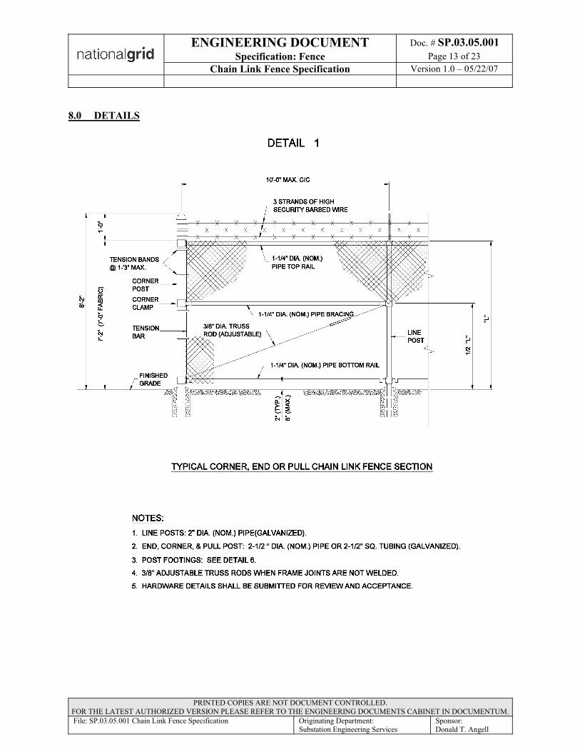
ENGINEERING DOCUMENT Doc. # SP.03.05.001Specification: Fence Page 13 of 23
Chain Link Fence Specification Version 1.0 – 05/22/07
PRINTED COPIES ARE NOT DOCUMENT CONTROLLED. FOR THE LATEST AUTHORIZED VERSION PLEASE REFER TO THE ENGINEERING DOCUMENTS CABINET IN DOCUMENTUM.File: SP.03.05.001 Chain Link Fence Specification Originating Department:
Substation Engineering ServicesSponsor:Donald T. Angell
8.0 DETAILS

ENGINEERING DOCUMENT Doc. # SP.03.05.001Specification: Fence Page 14 of 23
Chain Link Fence Specification Version 1.0 – 05/22/07
PRINTED COPIES ARE NOT DOCUMENT CONTROLLED. FOR THE LATEST AUTHORIZED VERSION PLEASE REFER TO THE ENGINEERING DOCUMENTS CABINET IN DOCUMENTUM.File: SP.03.05.001 Chain Link Fence Specification Originating Department:
Substation Engineering ServicesSponsor:Donald T. Angell
8.0 DETAILS (continued)
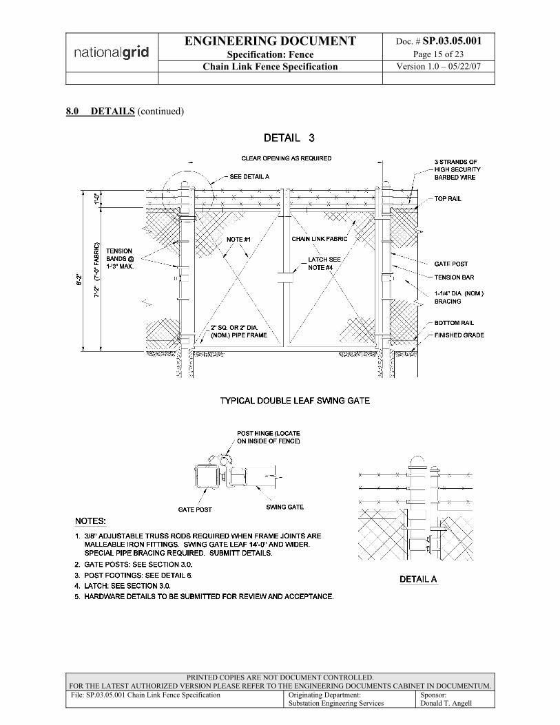
ENGINEERING DOCUMENT Doc. # SP.03.05.001Specification: Fence Page 15 of 23
Chain Link Fence Specification Version 1.0 – 05/22/07
PRINTED COPIES ARE NOT DOCUMENT CONTROLLED. FOR THE LATEST AUTHORIZED VERSION PLEASE REFER TO THE ENGINEERING DOCUMENTS CABINET IN DOCUMENTUM.File: SP.03.05.001 Chain Link Fence Specification Originating Department:
Substation Engineering ServicesSponsor:Donald T. Angell
8.0 DETAILS (continued)
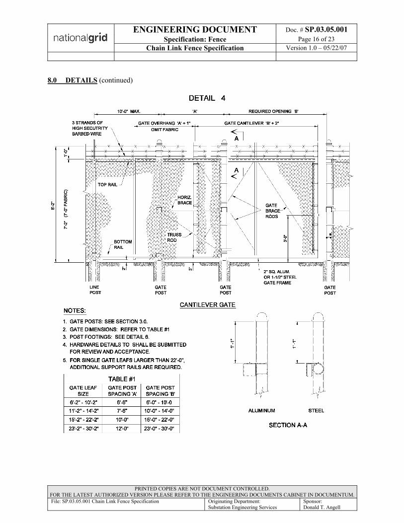
ENGINEERING DOCUMENT Doc. # SP.03.05.001Specification: Fence Page 16 of 23
Chain Link Fence Specification Version 1.0 – 05/22/07
PRINTED COPIES ARE NOT DOCUMENT CONTROLLED. FOR THE LATEST AUTHORIZED VERSION PLEASE REFER TO THE ENGINEERING DOCUMENTS CABINET IN DOCUMENTUM.File: SP.03.05.001 Chain Link Fence Specification Originating Department:
Substation Engineering ServicesSponsor:Donald T. Angell
8.0 DETAILS (continued)

ENGINEERING DOCUMENT Doc. # SP.03.05.001Specification: Fence Page 17 of 23
Chain Link Fence Specification Version 1.0 – 05/22/07
PRINTED COPIES ARE NOT DOCUMENT CONTROLLED. FOR THE LATEST AUTHORIZED VERSION PLEASE REFER TO THE ENGINEERING DOCUMENTS CABINET IN DOCUMENTUM.File: SP.03.05.001 Chain Link Fence Specification Originating Department:
Substation Engineering ServicesSponsor:Donald T. Angell
8.0 DETAILS (continued)

ENGINEERING DOCUMENT Doc. # SP.03.05.001Specification: Fence Page 18 of 23
Chain Link Fence Specification Version 1.0 – 05/22/07
PRINTED COPIES ARE NOT DOCUMENT CONTROLLED. FOR THE LATEST AUTHORIZED VERSION PLEASE REFER TO THE ENGINEERING DOCUMENTS CABINET IN DOCUMENTUM.File: SP.03.05.001 Chain Link Fence Specification Originating Department:
Substation Engineering ServicesSponsor:Donald T. Angell
8.0 DETAILS (continued)
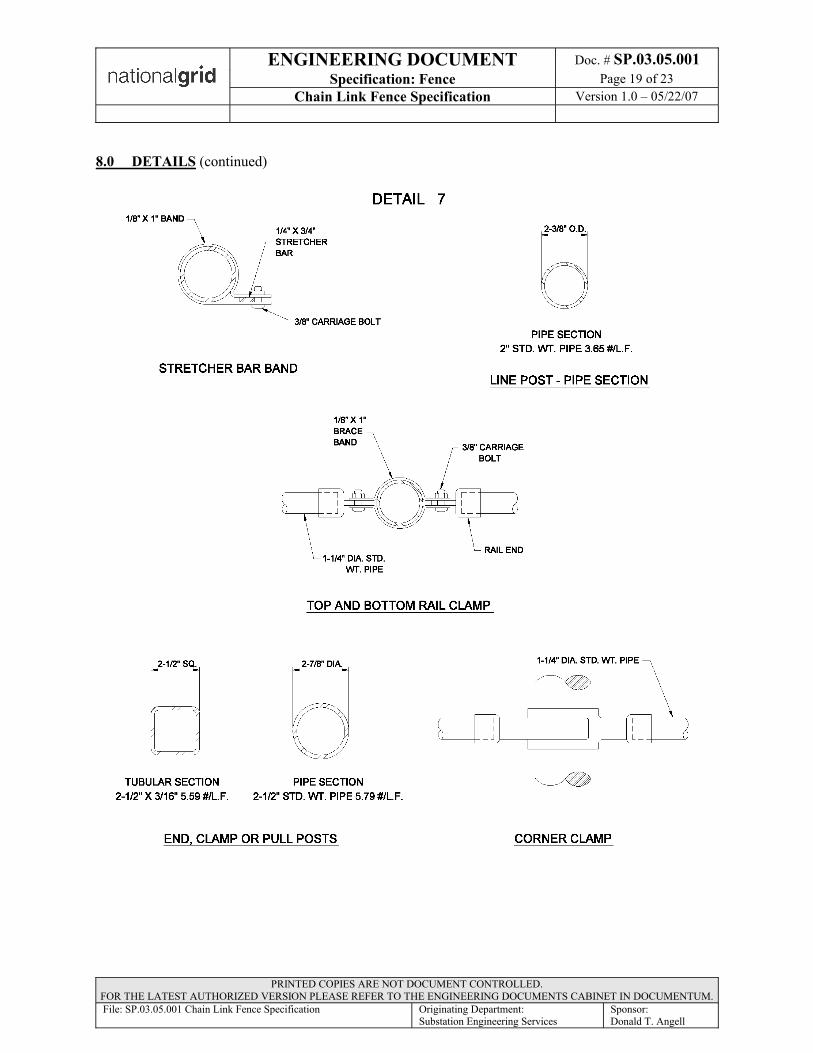
ENGINEERING DOCUMENT Doc. # SP.03.05.001Specification: Fence Page 19 of 23
Chain Link Fence Specification Version 1.0 – 05/22/07
PRINTED COPIES ARE NOT DOCUMENT CONTROLLED. FOR THE LATEST AUTHORIZED VERSION PLEASE REFER TO THE ENGINEERING DOCUMENTS CABINET IN DOCUMENTUM.File: SP.03.05.001 Chain Link Fence Specification Originating Department:
Substation Engineering ServicesSponsor:Donald T. Angell
8.0 DETAILS (continued)
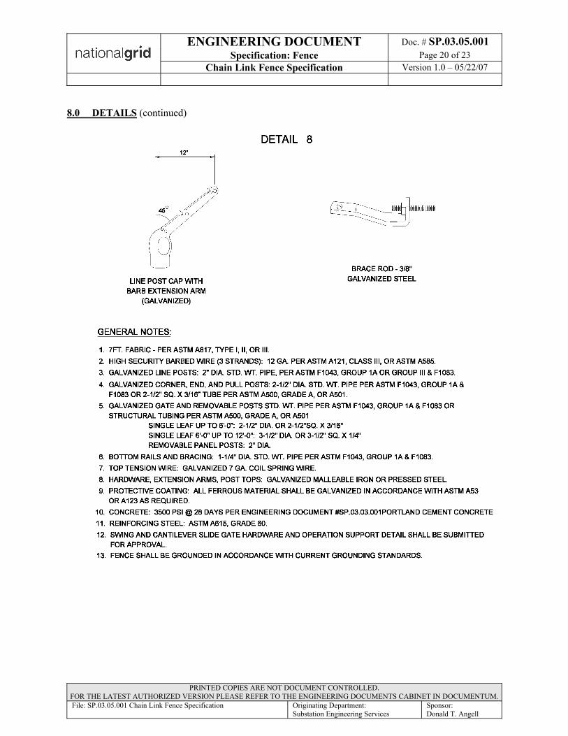
ENGINEERING DOCUMENT Doc. # SP.03.05.001Specification: Fence Page 20 of 23
Chain Link Fence Specification Version 1.0 – 05/22/07
PRINTED COPIES ARE NOT DOCUMENT CONTROLLED. FOR THE LATEST AUTHORIZED VERSION PLEASE REFER TO THE ENGINEERING DOCUMENTS CABINET IN DOCUMENTUM.File: SP.03.05.001 Chain Link Fence Specification Originating Department:
Substation Engineering ServicesSponsor:Donald T. Angell
8.0 DETAILS (continued)
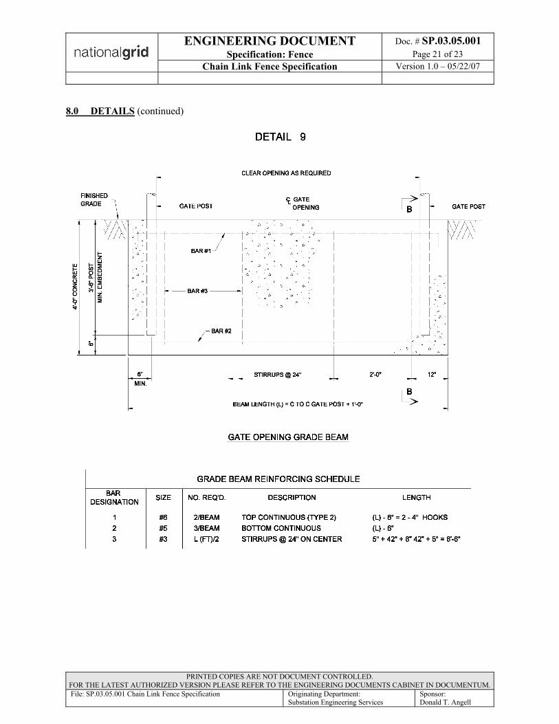
ENGINEERING DOCUMENT Doc. # SP.03.05.001Specification: Fence Page 21 of 23
Chain Link Fence Specification Version 1.0 – 05/22/07
PRINTED COPIES ARE NOT DOCUMENT CONTROLLED. FOR THE LATEST AUTHORIZED VERSION PLEASE REFER TO THE ENGINEERING DOCUMENTS CABINET IN DOCUMENTUM.File: SP.03.05.001 Chain Link Fence Specification Originating Department:
Substation Engineering ServicesSponsor:Donald T. Angell
8.0 DETAILS (continued)
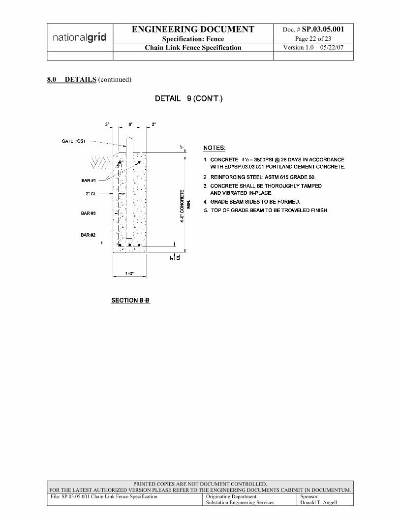
ENGINEERING DOCUMENT Doc. # SP.03.05.001Specification: Fence Page 22 of 23
Chain Link Fence Specification Version 1.0 – 05/22/07
PRINTED COPIES ARE NOT DOCUMENT CONTROLLED. FOR THE LATEST AUTHORIZED VERSION PLEASE REFER TO THE ENGINEERING DOCUMENTS CABINET IN DOCUMENTUM.File: SP.03.05.001 Chain Link Fence Specification Originating Department:
Substation Engineering ServicesSponsor:Donald T. Angell
8.0 DETAILS (continued)

ENGINEERING DOCUMENT Doc. # SP.03.05.001Specification: Fence Page 23 of 23
Chain Link Fence Specification Version 1.0 – 05/22/07
PRINTED COPIES ARE NOT DOCUMENT CONTROLLED. FOR THE LATEST AUTHORIZED VERSION PLEASE REFER TO THE ENGINEERING DOCUMENTS CABINET IN DOCUMENTUM.File: SP.03.05.001 Chain Link Fence Specification Originating Department:
Substation Engineering ServicesSponsor:Donald T. Angell
9.0 REVISION HISTORY
Version Date Description of Revision1.0 05/22/07 First version of new document. Based on and Supersedes NY document C-1004,
Rev. 03/01 and NE document GS 7105 issued 1/99.Section 3.1: Changed size of diamond link pattern from 2” to 1”.Standardized units to ” rather then inches.Summarized pipe sizes based on type of post in Table 1. Added SS-40 pipe sizes
as an acceptable alternate.Fabric ties - allow both NY and NE types.Post Holes - Removed requirement to taper hole out at the bottom, changed line
post and gate center stop foundation hole diameter from 10” to 12” and all other post holes to 16”. Standardized foundation hole depth to 4’.
Barbed wire - Allow zinc coated steel, aluminum coated steel or all aluminum.Fabric - 2” above grade with bottom rail. Exceptions noted in project design
drawings.Removed gate plunger rod. Specified Fence-Loc LatchAdded requirement to peen hardwareAdded coating repair and overnight securityReinforcing steel bar changed from Grade 40 to Grade 60NY Version - Removed references to Purchase Requisition and Purchase Order;
Eliminated Type III Aluminum-Zinc Alloy coated fabric; Changed barbed wirefrom on single strand to two twisted strands to match NE version; H posts deleted, Removed top tension wire, added top rail; Removed ground hole; Barbed wire - removed powder activated fastener requirement; Removed checklist.
NE Version - barb spacing changed from 4” to 3”; Removed ground clamp, gate frame changed to 2”; concrete information removed and to be included in separate specification; removed holdback device; removed guardrail
Added details and redrawn in CAD

Substation Engineering and Design - NY Rev. 2 - 5/22/2009 - Page 1
5/22/2009Project # 103014
BOM Item # TRC
In-Grnd ConstCont
Above-Grnd ConstCont
Type of Order Req/PT #
PO # or NM Sym # or Order # Quantity
Description Supplier Notes
A6 X Cable, 500MCM CU, 600V TRC to spec & request submittal Station service transformer secondary cable
A7 X 1/0 CU cable, 25kV with concentric neutral TRC to spec & request submittal Station service transformer primary cable
A8 X 40-15-916 12500 LF 9/16", 19/#9 Copperweld Cable Ground grid cable
A9 X 40-35-019 12500 LF Cable, Bare, 4/0 AWG, 19 strands, soft drawn copper Ground grid riser cable/Control house grounding wire
A10 X 40-15-035 Copper wire, bare, #2, solid, soft drawn
A11 X 40-15-002 Copper wire, bare, #6, solid, soft drawn
A12 X 35-03-039 350 LF Potential Equalizing Grid mesh, 8" x 8" x 6' 8" x 8" mesh is 6'-0" wide x 10'-0" long
A13 X 59-94-910 512 Ea Ground rod, copper clad, 3/4"x8'
A14 X 51-06-162 387 Ea Coupling, Ground Rod, 3/4 in, Bronze
A15 X 5996750 125 Ea Stud, Driving, 3/4 in Dia, 10 UNC, 2 in Long, Black Iron
A16 X Copper bar, 1/8" x 1: wide, 10" long Box Ground Bus. Order 96" long pieces. Field to cut, bend, drill and intall copper bar as shown on
A17 X LF Copper bar 1/4" x 2" Wide Ground Bus system
Control Buiding Ground Bus. Includesbus bar,spliceplates, mounting brackets, and standoff
insulators. Manufacturers: Storm Copper Components Co. 1-866-716-9773, Harger Lightning and Grounding (Local Distibutor - Electrolines, Inc
315-455-5701)A18 X 40-24-125 Wire, Switchboard, Type SIS, 600V, 1c #12 Str Cu
A19 X 40-24-147 Wire, Switchboard, Type SIS, 600V, 1c #14 Str Cu
A20 X 40-24-148 Wire, Switchboard, Type SIS, 600V, 1c #16 Str Cu
A21 X 40-24-211 Wire, Instrumentation, 600v, 1 twisted pair with individual shield, #16 awg, Copper
A22 X 40-24-213 Wire, Instrumentation, 600v, 3 twisted pairs with individual shield, #16 awg, Copper
A23 X 40-05-151 Wire, general purpose, Copper, XHHW, 1c #12, black AC heater circuits
A24 X 40-24-217 Wire, Instrumentation, 600v, 7 twisted pairs with individual shield, #16 awg, Copper
A25 X 40-24-219 Wire, Instrumentation, 600v, 9 twisted pairs with individual shield, #16 awg, Copper
A26 X 40-24-222 Wire, Instrumentation, 600v, 12 twisted pairs with individual shield, #16 awg, Copper
A27 X 40-24-227 Cable, Instrumentation. 600v, 7 twisted pair #16 with overall shield
A28 X 40-24-503 Cable, control, 600v, 3c #14 Copper, non-shielded
A29 X 40-05-152 Cable, general purpose, white, 600V, 1c #12
A30 X 40-24-509 Cable, control, 600v, 9c #14 Copper, non-shielded
A31 X 40-24-301 Cable, control, 600v, 1c #12 Copper, non-shielded
A32 X 40-24-302 Cable, control, 600v, 2c #12 Copper, non-shielded
A33 X 40-24-305 Cable, control, 600v, 5c #12 Copper, non-shielded
A34 X 40-24-309 Cable, control, 600v, 9c #12 Copper, non-shielded
A35 X 40-24-312 Cable, control, 600v, 12c #12 Copper, non-shielded
A36 X 40-24-319 Cable, control, 600v, 19c #12 Copper, non-shielded
A37 X 40-24-402 Cable, control, 600v, 2c #10 Copper, non-shielded
A38 X 40-24-403 Cable, control, 600v, 3c #10 Copper, non-shielded
A39 X 40-24-405 Cable, control, 600v, 5c #10 Copper, non-shielded
A40 X 40-24-412 Cable, control, 600v, 12c #10 Copper, non-shielded
A41 X 40-24-419 Cable, control, 600v, 19c #10 Copper, non-shielded
A42 X 40-24-425 Cable, control, 600v, 5c #10 Copper, shielded
A43 X Cable, Category 6, 600Mhz, Stranded, 4 pair, #24 AWG., Blue Jacket
A44 X Cable, Category 3 Phone circuits
A45 X Cable, Coax, RG58/U, 1000' reel, Non-Plenum, Belden 9310
A46 X Cable, Coax, RG213/U, 1000' reel, Non-Plenum
A47 X Cable, Belden #3106A
A48 X Cable, Belden #9841
B2 X EaEnclosure, 36"x36"x12", NEMA 4, Aluminum with 33"x33" subpanel and provisions for padlocking. Hoffman Catalog # NEED CATALOG
NUMBER NO Substitutions
CVT Junction Boxes (6), CT/VT Junction Boxes (2), PT Junction Boxes (2)
B5 X 20-10-464 Ea Conduit, 4", PVC, Bell end fitting Schedule 40
B6 X 20-11-167 Ea Conduit, 4", PVC, straight sections, 20' length Schedule 40
B7 X Ea Conduit, 4", PVC expansion connector. Carlon #E945N Schedule 40
B8 X 20-10-454 Ea Conduit, 4", PVC, Coupling Schedule 40
B9 X 20-10-434 Ea Conduit, 4", PVC to Galvanized, female adapter
B10 X Ea Conduit, 4", Galv., Bend, 90 degree, 36" radius
B11 X 20-11-024 Ea Conduit, 4", Galvanized, straight section, 10' length
B12 X 20-11-064 Ea Conduit, 4", Coupling, hot dipped galv mild rigid steel
B13 X Ea Connector, Conduit, 4", Insulated, straight, for flexible liquid tight. Appleton #STB-400
B14 X 20-11-100 Ea Conduit, 4", Insulated Grounding Bushing, plated malleable iron
B15 X 35-03-074 Ea Conduit, ground clamp for galvanized 4" - 5" steel conduit
B16 X 20-10-462 Ea Conduit, 2", PVC, Bell end fitting
B17 X 20-11-028 Ea Conduit, 2", PVC, straight sections, 20' length Schedule 40
B18 X Ea Conduit, 2", PVC expansion connector. Carlon #E945J Schedule 40
B19 X 20-10-452 Ea Conduit, 2", PVC, Coupling Schedule 40
Luther Forest Substation
Responsible to Order
Material List of Station Equipment Ordered as ofPROJECT:
Template: Material List Template.xls, Rev.3.4 File:Luther Forest Material List REV 2.xls
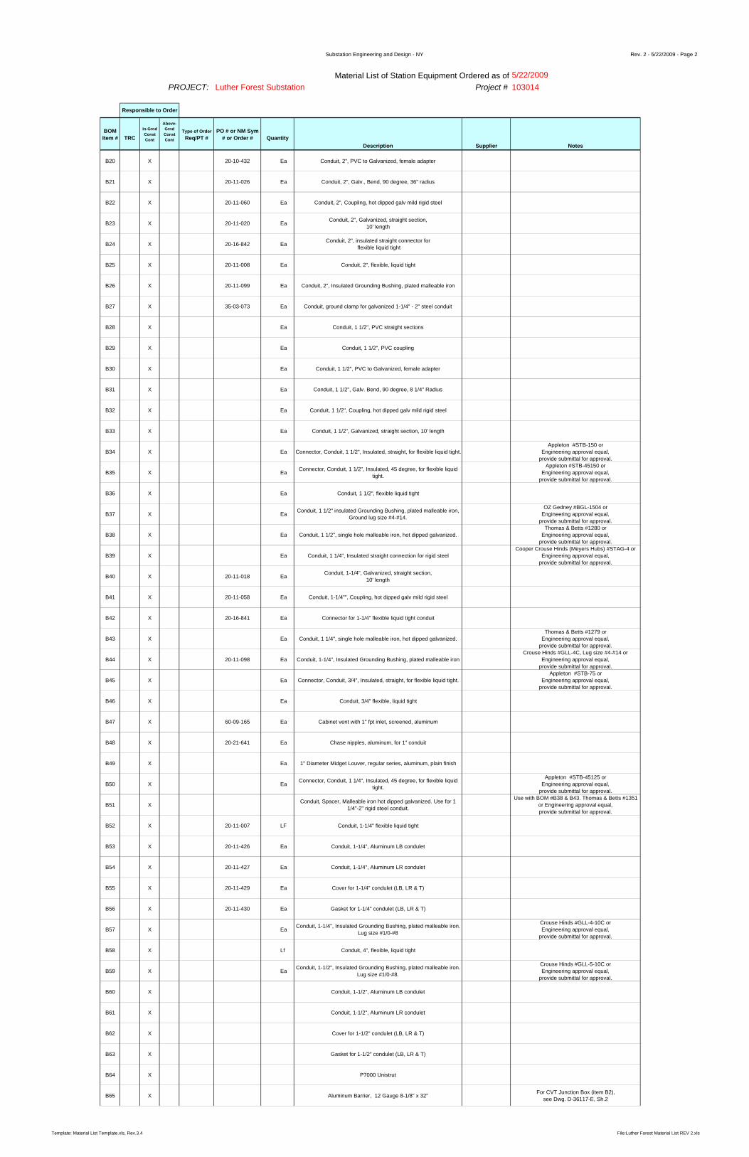
Substation Engineering and Design - NY Rev. 2 - 5/22/2009 - Page 2
5/22/2009Project # 103014
BOM Item # TRC
In-Grnd ConstCont
Above-Grnd ConstCont
Type of Order Req/PT #
PO # or NM Sym # or Order # Quantity
Description Supplier Notes
Luther Forest Substation
Responsible to Order
Material List of Station Equipment Ordered as ofPROJECT:
B20 X 20-10-432 Ea Conduit, 2", PVC to Galvanized, female adapter
B21 X 20-11-026 Ea Conduit, 2", Galv., Bend, 90 degree, 36" radius
B22 X 20-11-060 Ea Conduit, 2", Coupling, hot dipped galv mild rigid steel
B23 X 20-11-020 Ea Conduit, 2", Galvanized, straight section, 10' length
B24 X 20-16-842 Ea Conduit, 2", insulated straight connector for flexible liquid tight
B25 X 20-11-008 Ea Conduit, 2", flexible, liquid tight
B26 X 20-11-099 Ea Conduit, 2", Insulated Grounding Bushing, plated malleable iron
B27 X 35-03-073 Ea Conduit, ground clamp for galvanized 1-1/4" - 2" steel conduit
B28 X Ea Conduit, 1 1/2", PVC straight sections
B29 X Ea Conduit, 1 1/2", PVC coupling
B30 X Ea Conduit, 1 1/2", PVC to Galvanized, female adapter
B31 X Ea Conduit, 1 1/2", Galv. Bend, 90 degree, 8 1/4" Radius
B32 X Ea Conduit, 1 1/2", Coupling, hot dipped galv mild rigid steel
B33 X Ea Conduit, 1 1/2", Galvanized, straight section, 10' length
B34 X Ea Connector, Conduit, 1 1/2", Insulated, straight, for flexible liquid tight. Appleton #STB-150 or
Engineering approval equal, provide submittal for approval.
B35 X Ea Connector, Conduit, 1 1/2", Insulated, 45 degree, for flexible liquid tight.
Appleton #STB-45150 orEngineering approval equal,
provide submittal for approval.
B36 X Ea Conduit, 1 1/2", flexible liquid tight
B37 X Ea Conduit, 1 1/2" insulated Grounding Bushing, plated malleable iron, Ground lug size #4-#14.
OZ Gedney #BGL-1504 orEngineering approval equal,
provide submittal for approval.
B38 X Ea Conduit, 1 1/2", single hole malleable iron, hot dipped galvanized.Thomas & Betts #1280 or
Engineering approval equal, provide submittal for approval.
B39 X Ea Conduit, 1 1/4", Insulated straight connection for rigid steelCooper Crouse Hinds (Meyers Hubs) #STAG-4 or
Engineering approval equal, provide submittal for approval.
B40 X 20-11-018 Ea Conduit, 1-1/4", Galvanized, straight section, 10' length
B41 X 20-11-058 Ea Conduit, 1-1/4"", Coupling, hot dipped galv mild rigid steel
B42 X 20-16-841 Ea Connector for 1-1/4" flexible liquid tight conduit
B43 X Ea Conduit, 1 1/4", single hole malleable iron, hot dipped galvanized.Thomas & Betts #1279 or
Engineering approval equal, provide submittal for approval.
B44 X 20-11-098 Ea Conduit, 1-1/4", Insulated Grounding Bushing, plated malleable ironCrouse Hinds #GLL-4C, Lug size #4-#14 or
Engineering approval equal, provide submittal for approval.
B45 X Ea Connector, Conduit, 3/4", Insulated, straight, for flexible liquid tight.Appleton #STB-75 or
Engineering approval equal, provide submittal for approval.
B46 X Ea Conduit, 3/4" flexible, liquid tight
B47 X 60-09-165 Ea Cabinet vent with 1" fpt inlet, screened, aluminum
B48 X 20-21-641 Ea Chase nipples, aluminum, for 1" conduit
B49 X Ea 1" Diameter Midget Louver, regular series, aluminum, plain finish
B50 X Ea Connector, Conduit, 1 1/4", Insulated, 45 degree, for flexible liquid tight.
Appleton #STB-45125 orEngineering approval equal,
provide submittal for approval.
B51 X Conduit, Spacer, Malleable iron hot dipped galvanized. Use for 1 1/4"-2" rigid steel conduit.
Use with BOM #B38 & B43. Thomas & Betts #1351 or Engineering approval equal, provide submittal for approval.
B52 X 20-11-007 LF Conduit, 1-1/4" flexible liquid tight
B53 X 20-11-426 Ea Conduit, 1-1/4", Aluminum LB condulet
B54 X 20-11-427 Ea Conduit, 1-1/4", Aluminum LR condulet
B55 X 20-11-429 Ea Cover for 1-1/4" condulet (LB, LR & T)
B56 X 20-11-430 Ea Gasket for 1-1/4" condulet (LB, LR & T)
B57 X Ea Conduit, 1-1/4", Insulated Grounding Bushing, plated malleable iron. Lug size #1/0-#8
Crouse Hinds #GLL-4-10C orEngineering approval equal,
provide submittal for approval.
B58 X Lf Conduit, 4", flexible, liquid tight
B59 X Ea Conduit, 1-1/2", Insulated Grounding Bushing, plated malleable iron. Lug size #1/0-#8.
Crouse Hinds #GLL-5-10C orEngineering approval equal,
provide submittal for approval.
B60 X Conduit, 1-1/2", Aluminum LB condulet
B61 X Conduit, 1-1/2", Aluminum LR condulet
B62 X Cover for 1-1/2" condulet (LB, LR & T)
B63 X Gasket for 1-1/2" condulet (LB, LR & T)
B64 X P7000 Unistrut
B65 X Aluminum Barrier, 12 Gauge 8-1/8" x 32" For CVT Junction Box (item B2), see Dwg. D-36117-E, Sh.2
Template: Material List Template.xls, Rev.3.4 File:Luther Forest Material List REV 2.xls

Substation Engineering and Design - NY Rev. 2 - 5/22/2009 - Page 3
5/22/2009Project # 103014
BOM Item # TRC
In-Grnd ConstCont
Above-Grnd ConstCont
Type of Order Req/PT #
PO # or NM Sym # or Order # Quantity
Description Supplier Notes
Luther Forest Substation
Responsible to Order
Material List of Station Equipment Ordered as ofPROJECT:
B66 X LF Electric Channel, 1 5/8" x 1 5/8", GalvanizedUnistrut #P1000T-HG or
Engineering approval equal, provide submittal for approval.
B67 X Ea Pipe Clamp 1 1/2" steel conduit, galvanized, for use with 1 5/8" x 1 5/8" electric channel
Unistrut #P1115-HG orEngineering approval equal,
provide submittal for approval.
B68 X Ea Pipe Clamp 2" steel conduit, galvanized, for use with 1 5/8" x 1 5/8" electric channel
Unistrut #P1117-HG orEngineering approval equal,
provide submittal for approval.
B69 X Ea Pipe Clamp 4" steel conduit, galvanized, for use with 1 5/8" x 1 5/8" electric channel
Unistrut #P1121-HG orEngineering approval equal,
provide submittal for approval.
B71 X LF Standard Din Rail, 35 x 7mm
B72 X Ea Connector, Aluminum,straight strain relief flexible cord, sized for light fixture cord being supplied under BOM #E2
Thomas & Betts #2900AL series or Engineering approval equal,
provide submittal for approval.
B73 X Ea Conduit, 1 1/2", Insulated straight connection for rigid steelCooper Crouse Hinds (Meyers Hubs) #STAG-5 or
Engineering approval equal, provide submittal for approval.
B74 X Ea Conduit, 3/4", Insulated straight connection for rigid steelCooper Crouse Hinds (Meyers Hubs) #STAG-2 or
Engineering approval equal, provide submittal for approval.
B75 X Ea Enclosure, 12"x12"x6", NEMA 3 & 4, G-90 grade galvanized steel, screw cover with neoprene gasket.
Hubbell Wiegmann #WA121206GSCG No Substitutions
B76 X Ea Strain Relief Grip, Galvanized steel, single eye to support cable diameter range .43-.56 OD cable
Bryant #BDS43U orEngineering approval equal,
provide submittal for approval.
B77 X Ea Conduit, 3/4", Galvanized rigid steel, straight section,10' length
B78 X Ea Conduit, 3/4" insulated Grounding Bushing, plated malleable ironOZ Gedney #BGL-NEED CAT # or
Engineering approval equal, provide submittal for approval.
B79 X 0808585 LF Conduit, 4" Flexible Liquidtight
B80 X Ea Conduit, 3/4", single hole malleable iron, hot dipped galvanized.Thomas & Betts #1277 or
Engineering approval equal, provide submittal for approval.
B81 X Ea 1 1/2" PVC Bell End Schedule 40
B82 X Ea 1 1/2" PVC Expansion Connector Schedule 40
D21 X 20-07-823 Ea Connector #2 Solid -250 KCMIL Copper Cable to Flat. Cast Copper Alloy Body FCI Burndy #GB29 or equal
D22 X EaConnector, Compression, Parallel 1272 cables to NEMA 4 holepad,90 degree, Cables to have 8" spread, DMC Part
#CPLK9649D12720-8XDMC No Substitutions
D23 X Ea Connector, Ring Tongue, #2 Solid CU, 1/2" Bolt Amp
FCI Burndy #YA2CL-BOX or equal, Need a dieless hypress tool to crimp to #2 solid CU conductor. The
FCI Catalog number for this dieless tool is Y644HSXT [hand held hydraulic tool], or PAT644XT18V [battery operated tool] or
Engineering approval equal, provide submittal for approval.
D24 X 35-06-643 Ea Connector, tap, compression, Copper, 3/0-4/0 Run to 3/0-4/0 TapFCI Burndy #YC28C28 or
Engineering approval equal, provide submittal for approval.
D25 X 35-06-644 Ea Connector, tap, compression, Copper, 4/0 Run to #2 Tap
FCI Burndy #YC28C2 orEngineering approval equal,
provide submittal for approval.
D26 X 20-07-822 Ea Connector, Ground, #4 Sol to 2/0 Str Cable to Flat, Cast Copper Body
FCI Burndy #GB26 orEngineering approval equal,
provide submittal for approval.
D27 X 20-07-728 Ea Connector, compression, 1 hole terminal for #2 solid Copper wireAnderson Electric #VHCS-2-516 or
Engineering approval equal, provide submittal for approval.
D28 X 35-06-453 Ea Connector, Terminal, Compression Type, 4/0 Copper Cable to 2 Hole Flat Pad with NEMA Drilling.
FCI Burndy #YCA28-2N orEngineering approval equal,
provide submittal for approval.
D29 X 25 Ea Connector, cable to cable (9/16" 19/9 copperweld to 9/16" 19/9 copperweld), splice, CADWELD exothermic weld.
CADWELD Mold Part #SSC-9F. Contractor shall use all manufacturer recommended tools for connector
installation.No Substitutions
D30 X 400 EaConnector, cable to cable (9/16" 19/9 copperweld run to 4/0 19
strand soft drawn copper tap), horizontal tee, CADWELD exothermic weld.
CADWELD Mold Part #TAC-9F2Q. Contractor shall use all manufacturer recommended tools for
connector installation.No Substitutions
D31 X 125 Ea Connector, cable to cable (9/16" 19/9 copperweld run to 9/16" 19/9 copperweld tap), horizontal X, CADWELD exothermic weld.
CADWELD Mold Part #XBQ9F9F. Contractor shall use all manufacturer recommended tools for
connector installation.No Substitutions
D32 X 125 Ea Connector, cable to ground rod (9/16" 19/9 copperweld cable to 3/4" copperclad ground rod), CADWELD exothermic weld.
CADWELD Mold Part #GTC189F. Contractor shall use all manufacturer recommended tools for
connector installation.No Substitutions
D33 X 225 Ea Connector, split bolt, Run - #8 str., Tap - #8 solFCI Burndy #KSU-23 or
Engineering approval equal, provide submittal for approval.
D34 X 35-03-038 34 Ea Braid, Copper, flexible, Tinned, 18"L x 1"W, 200amp rating for fence gate grounding
D35 X 08-04-416 50 Ea Clamp, Ground, Bronze, U-Bolt Type, for 2'' Fence Post and #2/0 Solid-250 KCMIL Cable for fence gate grounding
D36 X 08-04-417 4 Ea Clamp, Ground, Bronze, U-Bolt Type, for 2.5" Fence Post and #2/0 Solid-250 KCMIL Cable for fence gate grounding
D37 X 08-04-418 4 Ea Clamp, Ground, Bronze, U-Bolt Type, for 3.5" Fence Post and #2/0 Solid-250 KCMIL Cable for fence gate grounding
D40 X 35-07-128 180 Ea Connector, compression, C type, Copper, 2 sol-2 str run to 8 sol-4str tap
FCI Burndy #YC2C4TN or Engineering approval equal,
provide submittal for approval.
E01 X HEATER, 80 WATT, 120 VOLT, 2 AMP, SELF REGULATING, DIN RAIL MOUNT, WITH ONE NEMA 4 VENT, DAYTON #4503
JUNCTION BOX HEATER. Each heater comes with air vent and din rail for heater mounting.
No Substitutions
E02 XFloodlight, High Pressure Sodium, 400WATT, Non Time Auto Switch Quartz (Quartz Re-Strike), Trunnion Mount, 208VOLT, Dark Bronze
Finish, Wide Uniform Beam (7x6)
Hubbell Outdoor Lighting Magnuliter MV Series #MVM-0400-S-268-QSS. (Specified fixture comes with a quad tap ballast wired for 277Volts. Fixture
shall be rewired in field for 208Volt operation.)or Engineering approval equal, provide submittal for approval.
E03 X 25-08-400 Lamp, High Pressure Sodium, 400W, 100v, Clear,Univ burning mogel base
GE Lighting #LU400, Philips #C400S51/ALTO, Sylvania #LU400/ECO
E04 X 4 Ea LIGHTING CONTACTOR, 30A, 12 POLE, 120V COIL, NEMA 1 ENCLOSURE, ELECTRICALLY HELD
SQUARE D CAT # LO1200V02 or Engineering approval equal,
provide submittal for approval.
E05 X 3 Ea General-Duty Safety Switch, 120/240 Volt, 30Amp, 2 pole solid neutral, NEMA 3R Heavy Duty, Gas Cart outlets
Template: Material List Template.xls, Rev.3.4 File:Luther Forest Material List REV 2.xls