lessons from the behavior of a monitored eleven story
TRANSCRIPT
Earthquake Spectra, online preprint, DOI: 10.1193/051813EQS126M
Lessons from the Behavior of a Monitored Eleven‐story Building during the 2011 Tohoku Earthquake for Robustness against Design Uncertainties
Zhe Qu,a) M.EERI, Hiroyasu Sakata,b) Saburoh Midorikawa,c) M.EERI, and
Akira Wada,d) M.EERI1
Specifically detailed pin-supported walls with steel dampers have been used to seismically strengthen an eleven-story steel reinforced concrete building. By looking at the observed damages and monitored motions of the building during the M9.0 Tohoku earthquake in 2011, it is demonstrated that nonstructural reinforced concrete partition walls have had major effects on its seismic behavior during the earthquake, the neglect of which constitutes a major design uncertainty. A finite element model used to assist the retrofit design is calibrated taking advantage of the accelerograms obtained during the earthquake. The results of nonlinear time-history analysis investigations with the modified model identify both the positive and negative effects of the nonstructural walls at various ground motion intensities, and suggest that pin-supported wall-frame system exhibits higher robustness against both record-to-record and modeling uncertainties than its counterpart bare frame does.
INTRODUCTION
The major earthquakes such as the 1985 Mexico City earthquake, the 1995 Hanshin-Awaji earthquake, the 1999 Kocaeli earthquake and the 2008 Wenchuan earthquake have witnessed reinforced concrete (RC) moment-resisting frames collapsed in undesirable weak story mechanism (Villaverde , 1991; AIJ, 1997; Sezen et al, 2003; Zhao et al, 2009). Except for the most widely accepted ‘strong column-weak beam’ principle in the seismic design of moment-resisting frames, many other solutions have been proposed for avoiding in-height damage concentration of a structure, e.g., the ‘spreader column’ by Akiyama and Takahashi (1986) and the hinged walls by Alavi and Krawinkler (2004). Flexible-based rocking walls with various additional energy dissipating schemes were also proposed for the seismic damage control of multi-story RC buildings (e.g., Holden et al. 2003; Restrepo and Rahman 2007; Ajrab et al. 2004; and Marriot et al. 2008). They share the common concept to take advantage of structural walls a) Institute of Engineering Mechanics, China Earthquake Administration, Sanhe, Hebei, 065201, China b) Structural Engineering Research Center, Tokyo Institute of Technology, Nagatsuta, Yokohama, 226-8503, Japan c) Department of Built Environment, Tokyo Institute of Technology, Nagatsuta, Yokohama, 226-8503, Japan d) Structural Engineering Research Center, Tokyo Institute of Technology, Nagatsuta, Yokohama, 226-8503, Japan
Z. QU, H. SAKATA, S. MIDORIKAWA, AND A. WADA
Earthquake Spectra, online preprint, DOI: 10.1193/051813EQS126M
for avoiding damage concentration and to release the rotational constraint at the bottom of the walls to make them essentially free of damage even under major earthquakes.
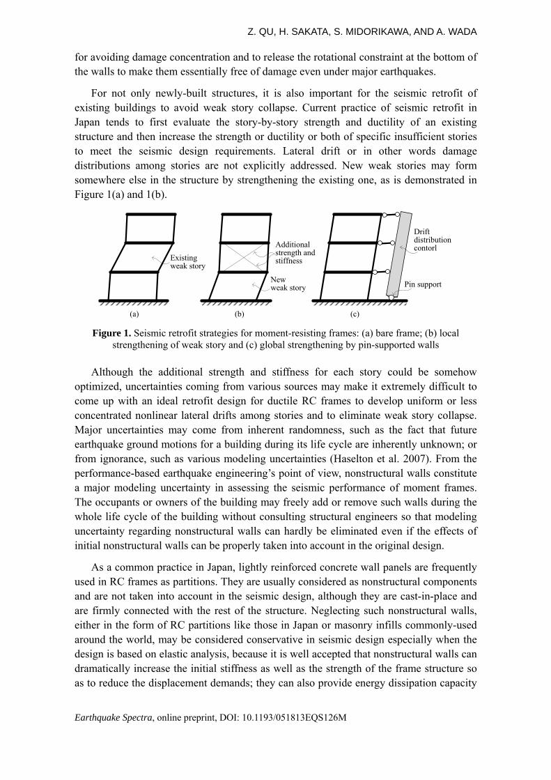
For not only newly-built structures, it is also important for the seismic retrofit of existing buildings to avoid weak story collapse. Current practice of seismic retrofit in Japan tends to first evaluate the story-by-story strength and ductility of an existing structure and then increase the strength or ductility or both of specific insufficient stories to meet the seismic design requirements. Lateral drift or in other words damage distributions among stories are not explicitly addressed. New weak stories may form somewhere else in the structure by strengthening the existing one, as is demonstrated in Figure 1(a) and 1(b).
Existingweak story
Additionalstrength and stiffness
Newweak story Pin support
Drift distribution contorl
(a) (b) (c)
Figure 1. Seismic retrofit strategies for moment-resisting frames: (a) bare frame; (b) local strengthening of weak story and (c) global strengthening by pin-supported walls
Although the additional strength and stiffness for each story could be somehow optimized, uncertainties coming from various sources may make it extremely difficult to come up with an ideal retrofit design for ductile RC frames to develop uniform or less concentrated nonlinear lateral drifts among stories and to eliminate weak story collapse. Major uncertainties may come from inherent randomness, such as the fact that future earthquake ground motions for a building during its life cycle are inherently unknown; or from ignorance, such as various modeling uncertainties (Haselton et al. 2007). From the performance-based earthquake engineering’s point of view, nonstructural walls constitute a major modeling uncertainty in assessing the seismic performance of moment frames. The occupants or owners of the building may freely add or remove such walls during the whole life cycle of the building without consulting structural engineers so that modeling uncertainty regarding nonstructural walls can hardly be eliminated even if the effects of initial nonstructural walls can be properly taken into account in the original design.
As a common practice in Japan, lightly reinforced concrete wall panels are frequently used in RC frames as partitions. They are usually considered as nonstructural components and are not taken into account in the seismic design, although they are cast-in-place and are firmly connected with the rest of the structure. Neglecting such nonstructural walls, either in the form of RC partitions like those in Japan or masonry infills commonly-used around the world, may be considered conservative in seismic design especially when the design is based on elastic analysis, because it is well accepted that nonstructural walls can dramatically increase the initial stiffness as well as the strength of the frame structure so as to reduce the displacement demands; they can also provide energy dissipation capacity
LESSONS FROM AN ELEVEN-STORY BUILDING IN TOHOKU EARTHQUAKE
Earthquake Spectra, online preprint, DOI: 10.1193/051813EQS126M
at least before they are severely damaged (e.g., Chaker and Cherifati, 1999; Hashemi and Mosalam, 2006; Pujol and Fick, 2010).
On the other hand, however, detrimental effects of nonstructural walls have also long been recognized. Nonstructural walls with openings may result in brittle shear failure of RC columns because of short column effects (Sugiyama et al. 2004). Plan eccentric nonstructural walls may stimulate torsional vibration of RC frames and increase the displacement demands for corner columns (Fardis et al. 1999). More significantly, brittle nonstructural walls are very likely to subject RC frames to weak story failure, which was examined by Negro and Colombo (1997) through a pseudo-dynamic test of three full-scale four-story RC frames with or without masonry infills. It was observed that weak story mechanism took place in the RC frame even if the masonry infills are uniformly distributed along height. Dolsek and Fajfar (2001) confirmed this observation by referring to the collapses of masonry infilled RC frames in the 1999 Koceali earthquake and showed through numerical analysis that weak story failure is very likely to take place if the ground motion intensity exceeds a certain level. Shake table test of a 2/3-scale three-story masonry infilled RC frame by Stavridis et al. (2012) also confirmed weak story failure at the bottom floor. The cast-in-place RC partition walls widely used in Japan may have the same, if not greater, negative effects because they also have large lateral stiffness and at the same time lack of ductility.
In contrast to the above mentioned story-by-story solutions for seismic retrofit, structural walls have much larger stiffness and strength as compared to individual RC columns and are thus expected to be more robust for controlling the distribution of lateral drifts of the building along the height and to mitigate the detrimental effect of nonstructural partition walls of inducing weak story failure. The reliability of the seismic performance of the walls can be further enhanced by releasing the rotational constraint at the base through rocking interface or artificial pin supports as shown in Figure 1(c). Such ideas were implemented in the seismic retrofit of three university buildings of Tokyo Institute of Technology during the past few years. Among them is the first application of the pin-supported wall-frame system, the G3 Building (Qu et al. (2012)).
THE G3 BUILDING WITH PIN-SUPPORTED WALLS
The G3 Building is an eleven-story steel reinforced concrete moment-resisting frame building filled with cast-in-place RC walls as nonstructural partitions (Figure 2(a)). It was completed in 1978, right after the M7.4 Miyagiken-oki earthquake, which led to a major revision of the seismic provisions of Japan in 1981. As concluded by a recent seismic inspection, there was an urgent need to strengthen the G3 Building.
It is obvious that the seismic design of the original moment frame did not follow the ‘strong column-weak beam’ principle. In the longitudinal frame, for example, the column cross section depth is generally 800 mm for all stories while the beam depth varies from 950 mm up to 2350 mm. Numerical analysis also confirmed that column hinge mechanism are very likely to take place at the bottom story or some upper stories depending on the characteristics of the input ground motion (see Figure 19(a) for reference).
Z. QU, H. SAKATA, S. MIDORIKAWA, AND A. WADA
Earthquake Spectra, online preprint, DOI: 10.1193/051813EQS126M
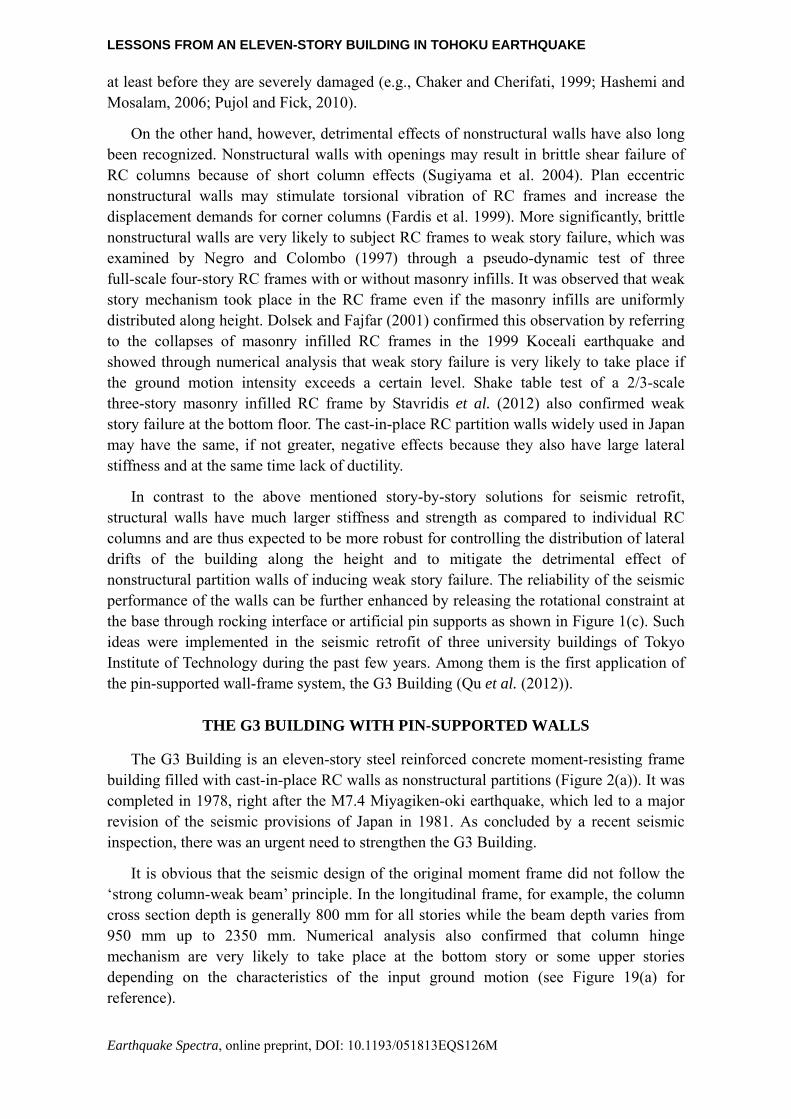
Taking advantage of the six slots evenly distributed along the perimeter of the original building, six post-tensioned (PT) concrete walls resting on specifically designed cast iron pin bearings were attached from outside of the building in the longitudinal direction. These post-tensioned pin-supported walls (refer to as ‘PS walls’ hereinafter) are expected to work as coordinators in the structural system to help control the distribution of lateral drifts along the height of the building and avoid weak story failure. Post-tensioning was applied to the walls to prevent cracking even under major earthquakes, making the performance of the PS walls more reliable. The bottom pin bearings can resist shear and axial compressive force while allowing for finite rotation without damage. In addition, shear-type steel dampers were installed in between the PS walls and original columns along the height of the building as energy dissipaters. More details of the retrofitting system of pin-supported walls can be found in Qu et al. (2012).
Figure 2. Structural systems of G3 Building: (a) before and (b) after retrofit.
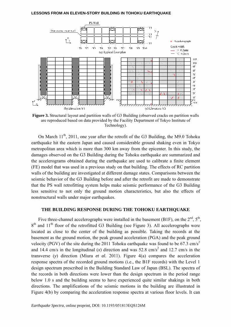
In addition to the structural system, the two inner bays of the longitudinal moment resisting frame, i.e., those along Axis Y2 and Y3 in Figure 3(a), are filled with lightly reinforced concrete partition walls. All wall piers are 120 mm thick, reinforced by single-layer orthogonal 10 rebars at 200 mm spacing, and are separated with RC columns by door openings. No boundary element or confinement is provided for the wall panels (See Figure 8 for reference). Such walls were believed too poorly detailed to be taken into account in either the seismic inspection or the retrofit design which followed.
In the transverse direction, however, six out of ten bays of the original frame are uniformly filled with 200 mm thick RC walls for all stories above the ground. These walls are reinforced by double-layer orthogonal 12 rebars at 200 mm spacing and are well confined by the neighboring columns as boundary elements. Such walls were believed effective in providing earthquake resistance and in avoiding weak story failure in the transverse direction of the building. As a result, the transvers structure was retrofitted by simply adding two conventional fixed-base shear walls at both ends of the building (along the X1 and X10 axis in Figure 3a) as well as strengthening some existing RC walls at the bottom stories along the X5 and X6 axis.
PS wall (1~11F)
Bottom pin bearing
Steel damper (2~9F)
Transverse shear wall (1~9F)
Bare frame (before retrofit) Pin-supported wall-frame (after retrofit)
(a) (b)
LESSONS FROM AN ELEVEN-STORY BUILDING IN TOHOKU EARTHQUAKE
Earthquake Spectra, online preprint, DOI: 10.1193/051813EQS126M
Figure 3. Structural layout and partition walls of G3 Building (observed cracks on partition walls
are reproduced based on data provided by the Facility Department of Tokyo Institute of Technology).
On March 11th, 2011, one year after the retrofit of the G3 Building, the M9.0 Tohoku earthquake hit the eastern Japan and caused considerable ground shaking even in Tokyo metropolitan area which is more than 300 km away from the epicenter. In this study, the damages observed on the G3 Building during the Tohoku earthquake are summarized and the accelerograms obtained during the earthquake are used to calibrate a finite element (FE) model that was used in a previous study on that building. The effects of RC partition walls of the building are investigated at different damage states. Comparisons between the seismic behavior of the G3 Building before and after the retrofit are made to demonstrate that the PS wall retrofitting system helps make seismic performance of the G3 Building less sensitive to not only the ground motion characteristics, but also the effects of nonstructural walls under major earthquakes.
THE BUILDING RESPONSE DURING THE TOHOKU EARTHQUAKE
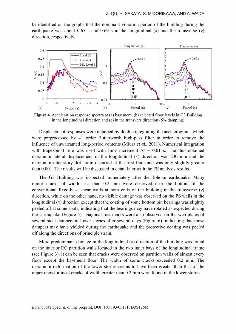
Five three-channel accelerographs were installed in the basement (B1F), on the 2nd, 5th, 8th and 11th floor of the retrofitted G3 Building (see Figure 3). All accelerographs were located as close to the center of the building as possible. Taking the records at the basement as the ground motion, the peak ground acceleration (PGA) and the peak ground velocity (PGV) of the site during the 2011 Tohoku earthquake was found to be 67.3 cm/s2 and 14.4 cm/s in the longitudinal (x) direction and was 52.8 cm/s2 and 12.7 cm/s in the transverse (y) direction (Miura et al. 2011). Figure 4(a) compares the acceleration response spectra of the recorded ground motions (i.e., the B1F records) with the Level 1 design spectrum prescribed in the Building Standard Law of Japan (BSL). The spectra of the records in both directions were lower than the design spectrum in the period range below 1.0 s and the building seems to have experienced quite similar shakings in both directions. The amplifications of the seismic motions in the building are illustrated in Figure 4(b) by comparing the acceleration response spectra at various floor levels. It can
Z. QU, H. SAKATA, S. MIDORIKAWA, AND A. WADA
Earthquake Spectra, online preprint, DOI: 10.1193/051813EQS126M
be identified on the graphs that the dominant vibration period of the building during the earthquake was about 0.65 s and 0.69 s in the longitudinal (x) and the transverse (y) direction, respectively.
Figure 4. Acceleration response spectra at (a) basement, (b) selected floor levels in G3 Building
in the longitudinal direction and (c) in the transvers direction (5% damping)
Displacement responses were obtained by double integrating the accelerograms which were preprocessed by 4th order Butterworth high-pass filter in order to remove the influence of unwarranted long-period contents (Miura et al., 2011). Numerical integration with trapezoidal rule was used with time increment t = 0.01 s. The thus-obtained maximum lateral displacement in the longitudinal (x) direction was 230 mm and the maximum inter-story drift ratio occurred at the first floor and was only slightly greater than 0.001. The results will be discussed in detail later with the FE analysis results.
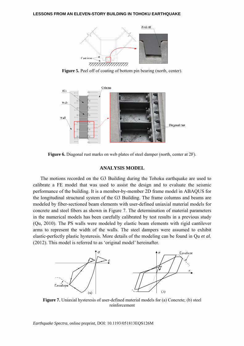
The G3 Building was inspected immediately after the Tohoku earthquake. Many minor cracks of width less than 0.2 mm were observed near the bottom of the conventional fixed-base shear walls at both ends of the building in the transverse (y) direction, while on the other hand, no visible damage was observed on the PS walls in the longitudinal (x) direction except that the coating of some bottom pin bearings was slightly peeled off at some spots, indicating that the bearings may have rotated as expected during the earthquake (Figure 5). Diagonal rust marks were also observed on the web plates of several steel dampers at lower stories after several days (Figure 6), indicating that those dampers may have yielded during the earthquake and the protective coating was peeled off along the directions of principle strain.
More predominant damage in the longitudinal (x) direction of the building was found on the interior RC partition walls located in the two inner bays of the longitudinal frame (see Figure 3). It can be seen that cracks were observed on partition walls of almost every floor except the basement floor. The width of some cracks exceeded 0.2 mm. The maximum deformation of the lower stories seems to have been greater than that of the upper ones for most cracks of width greater than 0.2 mm were found in the lower stories.
11F 8F 5F 2F B1F
11F 8F 5F 2F B1F
0.65 s 0.69 s
(b)
Longitudinal (x) Transverse (y)
(a) (c)
LESSONS FROM AN ELEVEN-STORY BUILDING IN TOHOKU EARTHQUAKE
Earthquake Spectra, online preprint, DOI: 10.1193/051813EQS126M
Figure 5. Peel off of coating of bottom pin bearing (north, center).
Figure 6. Diagonal rust marks on web plates of steel damper (north, center at 2F).
ANALYSIS MODEL
The motions recorded on the G3 Building during the Tohoku earthquake are used to calibrate a FE model that was used to assist the design and to evaluate the seismic performance of the building. It is a member-by-member 2D frame model in ABAQUS for the longitudinal structural system of the G3 Building. The frame columns and beams are modeled by fiber-sectioned beam elements with user-defined uniaxial material models for concrete and steel fibers as shown in Figure 7. The determination of material parameters in the numerical models has been carefully calibrated by test results in a previous study (Qu, 2010). The PS walls were modeled by elastic beam elements with rigid cantilever arms to represent the width of the walls. The steel dampers were assumed to exhibit elastic-perfectly plastic hysteresis. More details of the modeling can be found in Qu et al. (2012). This model is referred to as ‘original model’ hereinafter.
Figure 7. Uniaxial hysteresis of user-defined material models for (a) Concrete; (b) steel
reinforcement
Z. QU, H. SAKATA, S. MIDORIKAWA, AND A. WADA
Earthquake Spectra, online preprint, DOI: 10.1193/051813EQS126M
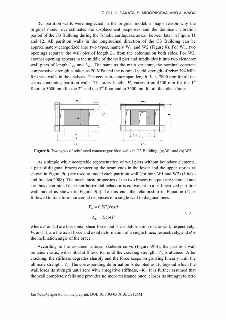
RC partition walls were neglected in the original model, a major reason why the original model overestimates the displacement responses and the dominant vibration period of the G3 Building during the Tohoku earthquake as can be seen later in Figure 11 and 12. All partition walls in the longitudinal direction of the G3 Building can be approximately categorized into two types, namely W1 and W2 (Figure 8). For W1, two openings separate the wall pier of length Lw from the columns on both sides. For W2, another opening appears in the middle of the wall pier and subdivides it into two slenderer wall piers of length Lw1 and Lw2. The same as the main structure, the nominal concrete compressive strength is taken as 20 MPa and the nominal yield strength of rebar 394 MPa for these walls in the analysis. The center-to-center span length, L, is 7800 mm for all the spans containing partition walls. The story height, H, varies from 4500 mm for the 1st floor, to 3600 mm for the 2nd and the 3rd floor and to 3500 mm for all the other floors.
Figure 8. Two types of reinforced concrete partition walls in G3 Building: (a) W1 and (b) W2.
As a simple while acceptable representation of wall piers without boundary elements, a pair of diagonal braces connecting the beam ends in the lower and the upper stories as shown in Figure 9(a) are used to model each partition wall (for both W1 and W2) (Hitaka and Imadzu 2008). The mechanical properties of the two braces in a pair are identical and are thus determined that their horizontal behavior is equivalent to a tri-linearized partition wall model as shown in Figure 9(b). To this end, the relationship in Equation (1) is followed to transform horizontal responses of a single wall to diagonal ones.
cos5.0b FF (1)
cosb
where F and are horizontal shear force and shear deformation of the wall, respectively; Fb and b are the axial force and axial deformation of a single brace, respectively, and is the inclination angle of the brace.
According to the assumed trilinear skeleton curve (Figure 9(b)), the partition wall remains elastic, with initial stiffness, K0, until the cracking strength, Vcr is attained. After cracking, the stiffness degrades sharply and the force keeps on growing linearly until the ultimate strength, Vu. The corresponding deformation is denoted as 0, beyond which the wall loses its strength until zero with a negative stiffness, –K0. It is further assumed that the wall completely fails and provides no more resistance once it loses its strength to zero

LESSONS FROM AN ELEVEN-STORY BUILDING IN TOHOKU EARTHQUAKE
Earthquake Spectra, online preprint, DOI: 10.1193/051813EQS126M
in either direction. Besides, the following hysteresis rules are assumed: (1) unloading branch always points to the cracking point in the opposite direction; (2) reloading branch would point to the cracking point or the ultimate strength point if these points have not yet been exceeded, and (3) otherwise, the reloading branch points to the largest deformation point ever experienced in the loading history.
Vu
F
Vcr
0
K0
u
0u
Vu
Vcr
(a) (b)
FailureK0
Figure 9. Model of partition walls: (a) Diagonal brace configuration and (b) hysteretic behavior.
For W1, the initial stiffness, K0, can be simply estimated by Equation (2), which accounts for both elastic flexural and shear stiffness assuming both the lower and upper ends fixed.
w
3w
ww
wfs0
12
1
11
1
EI
h
LGt
hKKK
(2)
where hw, tw, Lw are the height, thickness and length of a single wall pier, respectively; E and G is the elastic modulus and the shear modulus of concrete; Iw is the moment of inertia of a single wall pier cross section.
For W2, the stiffness of the two smaller wall piers which are separated by the central opening is first estimated by Equation (2) separately and then summed up to obtain the overall stiffness.
The cracking strength, Vcr, is estimated by Equation (3) proposed by AIJ (1999) for RC walls without boundary elements. The ultimate strength, Vu, is estimated by the empirical equation proposed by Wood (1990) for RC squat walls (Equation 4). Although simple, this equation was confirmed by Gulec et al. (2008) to give best prediction of ultimate strength among several other alternatives. For W2 cases, the strength of the two smaller wall piers are first calculated separately and then summed up to get the overall strength. The displacement corresponding to the ultimate strength, 0, is determined by the proposal of Li and Xiang (2011) for the effective stiffness of squat walls, Keff (Equation 5 and 6).
5.1/wwcrcr LtV (3)
where cr = 0.33√fc is the effective shear strength of concrete (fc in MPa).

Z. QU, H. SAKATA, S. MIDORIKAWA, AND A. WADA
Earthquake Spectra, online preprint, DOI: 10.1193/051813EQS126M
cwwyvyucww 6
545.0 fLtfAVfLt (4)
where fc is the compressive concrete strength, Avy is the total area of vertical reinforcement and fy is the yield strength of rebar.
eff
u0 K
V (5)
2w
2w
w
w
y3w
weff 31.037.053.0
1912
L
h
L
h
fh
EIK (6)
The configuration of the concrete partition walls in the modified model strictly follows their actual configuration in the G3 Building except for the idealization of a few irregular wall piers that differ from W1 and W2 pattern. The material parameters used in the above equations for the walls are simply derived from the assumed 20 MPa concrete and 394 MPa steel for the partition walls, without any trial-and-error calibrating process.
By simply removing the PS walls and the steel dampers from the above-mentioned modified model, a modified model for the un-retrofitted bare frame can also be obtained. As a result, a total of four models as listed in Table 1 are present. For convenience of narration, the un-retrofitted bare frame is referred to as ‘BF’ hereinafter and the one after the retrofit as ‘PS Wall-F’ for the pin-supported wall-frame. A letter ‘P’ for ‘partition’ is added to distinguish the modified models from the original ones.
Table 1. Summary of analysis models used in this study
Description Model ID PS Wall + Steel damper
Partition wall
Original model
Bare frame w/o partition walls BF × ×
PS wall-frame w/o partition walls PS Wall-F ○ ×
Modified model
Bare frame with partition walls BF-P × ○
PS wall-frame with partition walls PS Wall-F-P ○ ○
×: without, ○: with.
The validity of the modified model is checked by comparing its fundamental vibration periods with the microtremor observations during the retrofit construction by Hirano et al. (2011), which are listed in Table 2. It is seen that the fundamental vibration periods of the original models both before and after the retrofit (i.e., ‘BF’ and ‘PS Wall-F’ models) are considerably longer than the observed ones. On the other hand, the fundamental periods of the modified models (0.52 s for ‘BF-P’ and 0.49 s for ‘PS Wall-F-P’) are considered close enough to those obtained by on-site microtremor observations (i.e., 0.51 s and 0.47 s before and after the retrofit, respectively) (Table 2). The comparisons between the fundamental periods given by the original and modified models also indicate that the nonstructural partition walls increase the initial stiffness by at least 170% for the bare frame and by 90% for the PS wall-frame.
In addition to the consideration of partition walls in the model, the following
LESSONS FROM AN ELEVEN-STORY BUILDING IN TOHOKU EARTHQUAKE
Earthquake Spectra, online preprint, DOI: 10.1193/051813EQS126M
modifications were also made for the modified model to better represent the as-built building.
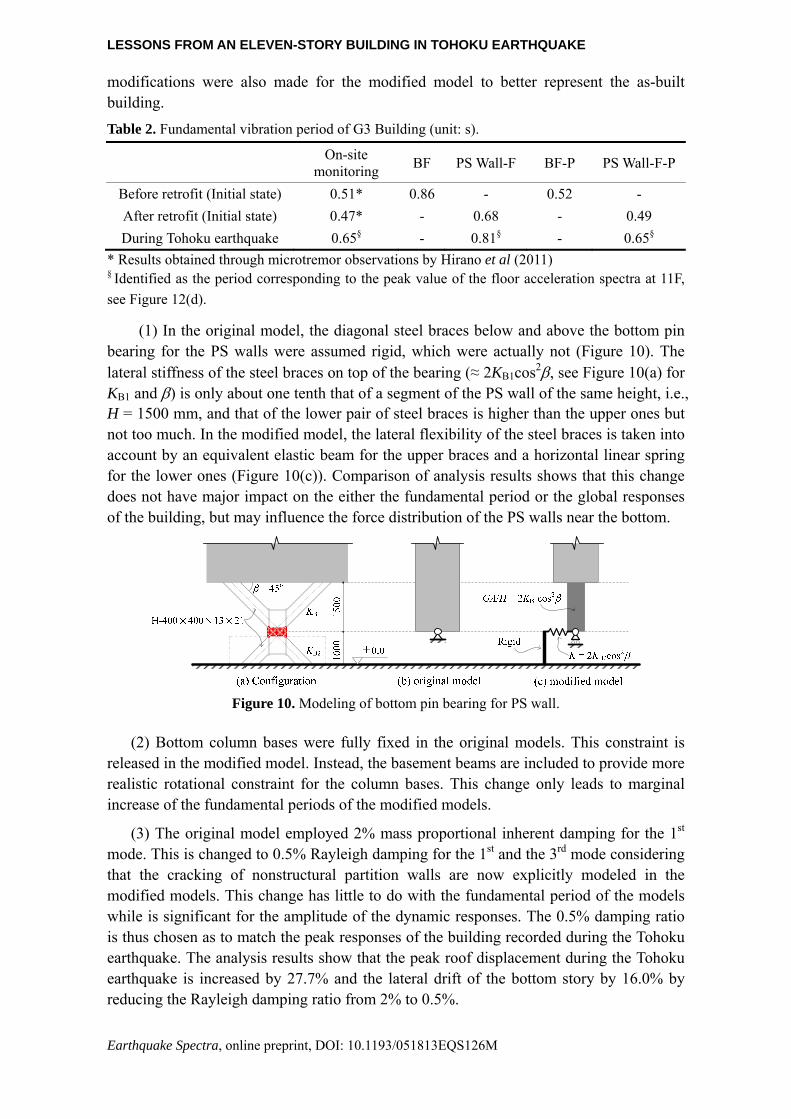
Table 2. Fundamental vibration period of G3 Building (unit: s).
On-site
monitoring BF PS Wall-F BF-P PS Wall-F-P
Before retrofit (Initial state) 0.51* 0.86 - 0.52 -
After retrofit (Initial state) 0.47* - 0.68 - 0.49
During Tohoku earthquake 0.65§ - 0.81§ - 0.65§
* Results obtained through microtremor observations by Hirano et al (2011) § Identified as the period corresponding to the peak value of the floor acceleration spectra at 11F,
see Figure 12(d).
(1) In the original model, the diagonal steel braces below and above the bottom pin bearing for the PS walls were assumed rigid, which were actually not (Figure 10). The lateral stiffness of the steel braces on top of the bearing (≈ 2KB1cos2, see Figure 10(a) for KB1 and ) is only about one tenth that of a segment of the PS wall of the same height, i.e., H = 1500 mm, and that of the lower pair of steel braces is higher than the upper ones but not too much. In the modified model, the lateral flexibility of the steel braces is taken into account by an equivalent elastic beam for the upper braces and a horizontal linear spring for the lower ones (Figure 10(c)). Comparison of analysis results shows that this change does not have major impact on the either the fundamental period or the global responses of the building, but may influence the force distribution of the PS walls near the bottom.
Figure 10. Modeling of bottom pin bearing for PS wall.
(2) Bottom column bases were fully fixed in the original models. This constraint is released in the modified model. Instead, the basement beams are included to provide more realistic rotational constraint for the column bases. This change only leads to marginal increase of the fundamental periods of the modified models.
(3) The original model employed 2% mass proportional inherent damping for the 1st mode. This is changed to 0.5% Rayleigh damping for the 1st and the 3rd mode considering that the cracking of nonstructural partition walls are now explicitly modeled in the modified models. This change has little to do with the fundamental period of the models while is significant for the amplitude of the dynamic responses. The 0.5% damping ratio is thus chosen as to match the peak responses of the building recorded during the Tohoku earthquake. The analysis results show that the peak roof displacement during the Tohoku earthquake is increased by 27.7% and the lateral drift of the bottom story by 16.0% by reducing the Rayleigh damping ratio from 2% to 0.5%.
Z. QU, H. SAKATA, S. MIDORIKAWA, AND A. WADA
Earthquake Spectra, online preprint, DOI: 10.1193/051813EQS126M
ANALYSIS RESULTS
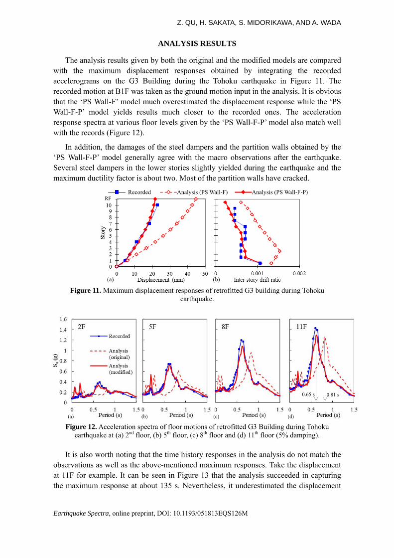
The analysis results given by both the original and the modified models are compared with the maximum displacement responses obtained by integrating the recorded accelerograms on the G3 Building during the Tohoku earthquake in Figure 11. The recorded motion at B1F was taken as the ground motion input in the analysis. It is obvious that the ‘PS Wall-F’ model much overestimated the displacement response while the ‘PS Wall-F-P’ model yields results much closer to the recorded ones. The acceleration response spectra at various floor levels given by the ‘PS Wall-F-P’ model also match well with the records (Figure 12).
In addition, the damages of the steel dampers and the partition walls obtained by the ‘PS Wall-F-P’ model generally agree with the macro observations after the earthquake. Several steel dampers in the lower stories slightly yielded during the earthquake and the maximum ductility factor is about two. Most of the partition walls have cracked.
Figure 11. Maximum displacement responses of retrofitted G3 building during Tohoku
earthquake.
Figure 12. Acceleration spectra of floor motions of retrofitted G3 Building during Tohoku
earthquake at (a) 2nd floor, (b) 5th floor, (c) 8th floor and (d) 11th floor (5% damping).
It is also worth noting that the time history responses in the analysis do not match the observations as well as the above-mentioned maximum responses. Take the displacement at 11F for example. It can be seen in Figure 13 that the analysis succeeded in capturing the maximum response at about 135 s. Nevertheless, it underestimated the displacement
(a)
0.65 s 0.81 s
(b) (c) (d)
(a) (b)
RF Recorded Analysis (PS Wall-F) Analysis (PS Wall-F-P)
LESSONS FROM AN ELEVEN-STORY BUILDING IN TOHOKU EARTHQUAKE
Earthquake Spectra, online preprint, DOI: 10.1193/051813EQS126M
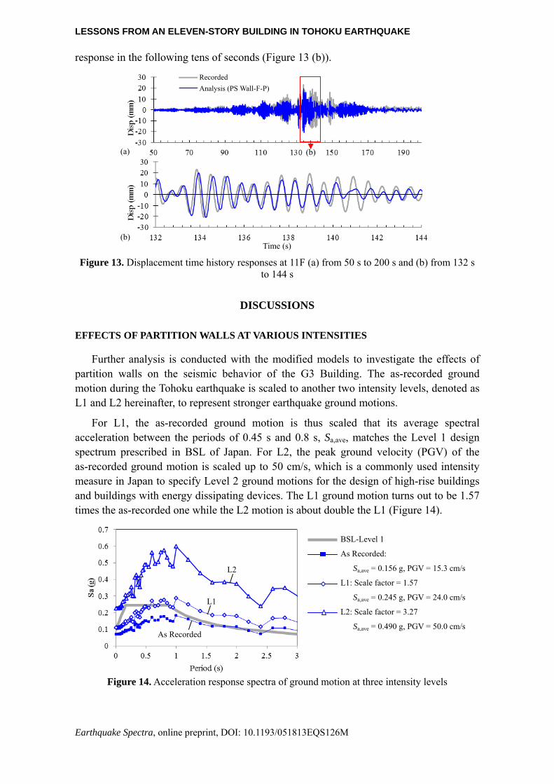
response in the following tens of seconds (Figure 13 (b)).
Figure 13. Displacement time history responses at 11F (a) from 50 s to 200 s and (b) from 132 s
to 144 s
DISCUSSIONS
EFFECTS OF PARTITION WALLS AT VARIOUS INTENSITIES
Further analysis is conducted with the modified models to investigate the effects of partition walls on the seismic behavior of the G3 Building. The as-recorded ground motion during the Tohoku earthquake is scaled to another two intensity levels, denoted as L1 and L2 hereinafter, to represent stronger earthquake ground motions.
For L1, the as-recorded ground motion is thus scaled that its average spectral acceleration between the periods of 0.45 s and 0.8 s, Sa,ave, matches the Level 1 design spectrum prescribed in BSL of Japan. For L2, the peak ground velocity (PGV) of the as-recorded ground motion is scaled up to 50 cm/s, which is a commonly used intensity measure in Japan to specify Level 2 ground motions for the design of high-rise buildings and buildings with energy dissipating devices. The L1 ground motion turns out to be 1.57 times the as-recorded one while the L2 motion is about double the L1 (Figure 14).
Figure 14. Acceleration response spectra of ground motion at three intensity levels
(a)
(b) Time (s)
(b)
Recorded
Analysis (PS Wall-F-P)
BSL-Level 1
As Recorded:
Sa,ave = 0.156 g, PGV = 15.3 cm/s
L1: Scale factor = 1.57
Sa,ave = 0.245 g, PGV = 24.0 cm/s
L2: Scale factor = 3.27
Sa,ave = 0.490 g, PGV = 50.0 cm/s As Recorded
L1
L2

Z. QU, H. SAKATA, S. MIDORIKAWA, AND A. WADA
Earthquake Spectra, online preprint, DOI: 10.1193/051813EQS126M
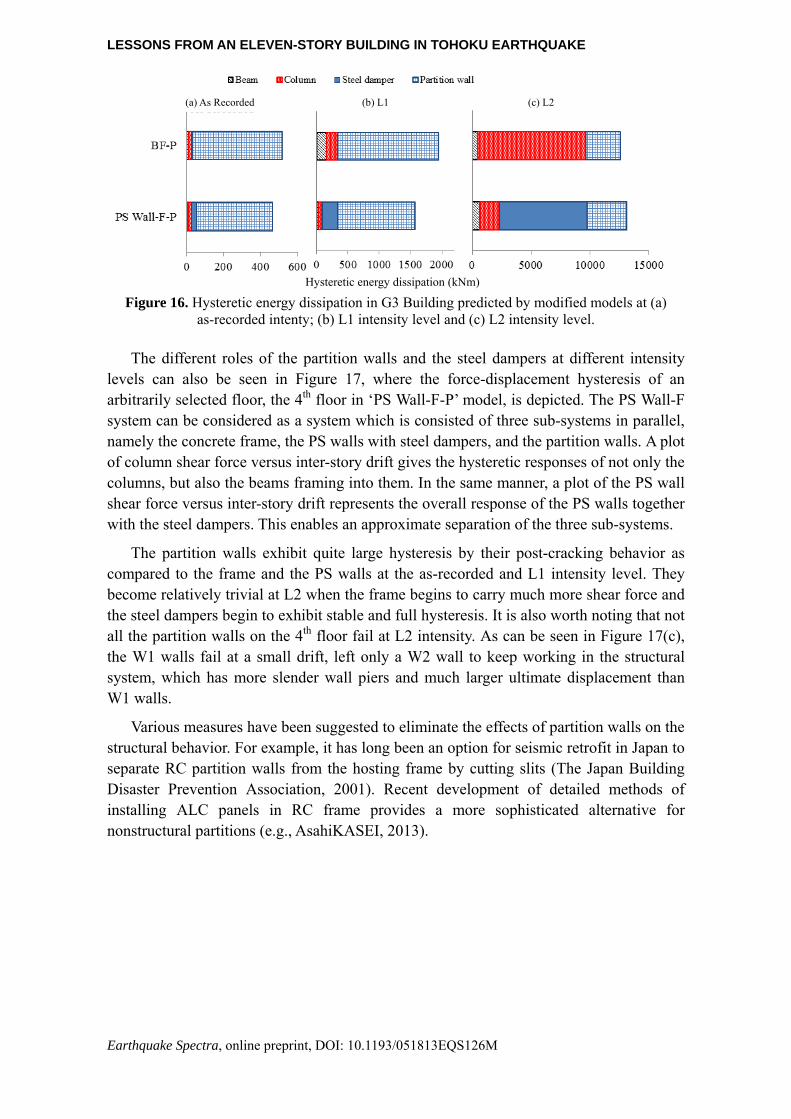
The analysis results show that the building should be quite safe under the as-recorded ground motion, no matter it is retrofitted or not. The maximum inter-story drift ratio would not exceed 1/600 in either case, although the inter-story drift would be larger for the un-retrofitted building (Figure 15(a)). Under such small deformations, the concrete frame remains essentially elastic and additional control of its deformation pattern is not critical for its seismic performance. Meanwhile, most hysteretic energy dissipation goes to the partition walls in both cases (i.e., ‘BF-P’ and ‘PS Wall-F-P’), which attract very large lateral force and crack at very early stages. Since only a few steel dampers slightly yield, the energy dissipated by the dampers is very limited (Figure 16(a)).
The partition walls still contribute most to the hysteretic energy dissipation among other types of components under L1 ground motion, although the concrete columns and beams in the ‘BF-P’ model or the steel dampers in ‘PS Wall-F-P’ model dissipate much more energy than they do under the as-recorded level (Figure 16(b)). On the other hand, the inter-story drifts tend to concentrate at some lower stories in ‘BF-P’ model while the PS walls are doing a good job in keeping the inter-story drift uniformly distributed in ‘PS Wall-F-P’ model (Figure 15(b)).
As the intensity is further increased to L2, the ‘BF-P’ model collapses at its first floor while the inter-story drift ratios of the other floors are still below 0.7%. Still, ‘PS Wall-F-P’ model exhibits quite uniform distribution of inter-story drifts (Figure 15(c)). At this intensity level, most partition walls suffer from brittle failure and lose their energy dissipating capacity. Accordingly, most hysteretic energy dissipation goes to the frame columns in ‘BF-P’ model or to the steel dampers in ‘PS Wall-F-P’ model (Figure 16(c)).
It is clear from the above results that both the steel dampers (together with the PS walls) and the partition walls dissipate a large amount of energy, thus protecting the concrete frame of the building at different levels of seismic intensities. The partition walls may have a beneficial effect on the seismic behavior of the building under minor or moderate earthquakes by providing stiffness and energy dissipation. However, this beneficial effect may diminish and even turns into a detrimental one under major earthquakes, as will be discussed later.
Figure 15. Maximum displacement response of G3 Building predicted by modified models at (a)
as recorded intenty; (b) L1 intensity level and (c) L2 intensity level.
to 0.033
(b) (c)(a)
LESSONS FROM AN ELEVEN-STORY BUILDING IN TOHOKU EARTHQUAKE
Earthquake Spectra, online preprint, DOI: 10.1193/051813EQS126M
Figure 16. Hysteretic energy dissipation in G3 Building predicted by modified models at (a)
as-recorded intenty; (b) L1 intensity level and (c) L2 intensity level.
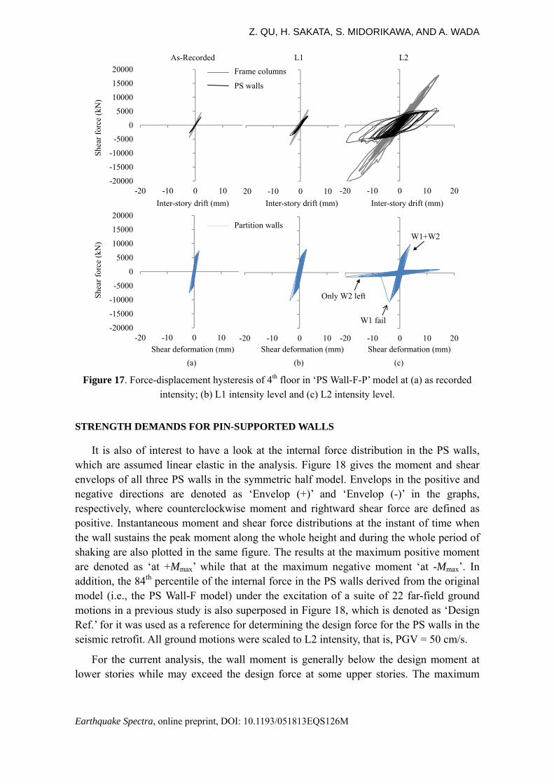
The different roles of the partition walls and the steel dampers at different intensity levels can also be seen in Figure 17, where the force-displacement hysteresis of an arbitrarily selected floor, the 4th floor in ‘PS Wall-F-P’ model, is depicted. The PS Wall-F system can be considered as a system which is consisted of three sub-systems in parallel, namely the concrete frame, the PS walls with steel dampers, and the partition walls. A plot of column shear force versus inter-story drift gives the hysteretic responses of not only the columns, but also the beams framing into them. In the same manner, a plot of the PS wall shear force versus inter-story drift represents the overall response of the PS walls together with the steel dampers. This enables an approximate separation of the three sub-systems.
The partition walls exhibit quite large hysteresis by their post-cracking behavior as compared to the frame and the PS walls at the as-recorded and L1 intensity level. They become relatively trivial at L2 when the frame begins to carry much more shear force and the steel dampers begin to exhibit stable and full hysteresis. It is also worth noting that not all the partition walls on the 4th floor fail at L2 intensity. As can be seen in Figure 17(c), the W1 walls fail at a small drift, left only a W2 wall to keep working in the structural system, which has more slender wall piers and much larger ultimate displacement than W1 walls.
Various measures have been suggested to eliminate the effects of partition walls on the structural behavior. For example, it has long been an option for seismic retrofit in Japan to separate RC partition walls from the hosting frame by cutting slits (The Japan Building Disaster Prevention Association, 2001). Recent development of detailed methods of installing ALC panels in RC frame provides a more sophisticated alternative for nonstructural partitions (e.g., AsahiKASEI, 2013).
Hysteretic energy dissipation (kNm)
(a) As Recorded (b) L1 (c) L2
Z. QU, H. SAKATA, S. MIDORIKAWA, AND A. WADA
Earthquake Spectra, online preprint, DOI: 10.1193/051813EQS126M
Figure 17. Force-displacement hysteresis of 4th floor in ‘PS Wall-F-P’ model at (a) as recorded
intensity; (b) L1 intensity level and (c) L2 intensity level.
STRENGTH DEMANDS FOR PIN-SUPPORTED WALLS
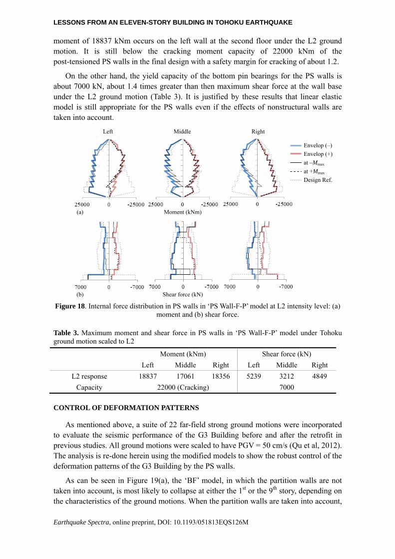
It is also of interest to have a look at the internal force distribution in the PS walls, which are assumed linear elastic in the analysis. Figure 18 gives the moment and shear envelops of all three PS walls in the symmetric half model. Envelops in the positive and negative directions are denoted as ‘Envelop (+)’ and ‘Envelop (-)’ in the graphs, respectively, where counterclockwise moment and rightward shear force are defined as positive. Instantaneous moment and shear force distributions at the instant of time when the wall sustains the peak moment along the whole height and during the whole period of shaking are also plotted in the same figure. The results at the maximum positive moment are denoted as ‘at +Mmax’ while that at the maximum negative moment ‘at -Mmax’. In addition, the 84th percentile of the internal force in the PS walls derived from the original model (i.e., the PS Wall-F model) under the excitation of a suite of 22 far-field ground motions in a previous study is also superposed in Figure 18, which is denoted as ‘Design Ref.’ for it was used as a reference for determining the design force for the PS walls in the seismic retrofit. All ground motions were scaled to L2 intensity, that is, PGV = 50 cm/s.
For the current analysis, the wall moment is generally below the design moment at lower stories while may exceed the design force at some upper stories. The maximum
-20000
-15000
-10000
-5000
0
5000
10000
15000
20000
-20 -10 0 10 20-20 -10 0 10 20
-20000
-15000
-10000
-5000
0
5000
10000
15000
20000
-20 -10 0 10 20-20000
-15000
-10000
-5000
0
5000
10000
15000
20000
-20 -10 0 10
-20000
-15000
-10000
-5000
0
5000
10000
15000
20000
-20 -10 0 10
Shea
r fo
rce
(kN
) Sh
ear
forc
e (k
N)
Inter-story drift (mm) Inter-story drift (mm) Inter-story drift (mm)
Shear deformation (mm) Shear deformation (mm) Shear deformation (mm)
Frame columns
PS walls
As-Recorded L1 L2
(a) (b) (c)
Partition walls
-20 -10 0 10 20
Only W2 left
W1 fail
W1+W2
LESSONS FROM AN ELEVEN-STORY BUILDING IN TOHOKU EARTHQUAKE
Earthquake Spectra, online preprint, DOI: 10.1193/051813EQS126M
moment of 18837 kNm occurs on the left wall at the second floor under the L2 ground motion. It is still below the cracking moment capacity of 22000 kNm of the post-tensioned PS walls in the final design with a safety margin for cracking of about 1.2.
On the other hand, the yield capacity of the bottom pin bearings for the PS walls is about 7000 kN, about 1.4 times greater than then maximum shear force at the wall base under the L2 ground motion (Table 3). It is justified by these results that linear elastic model is still appropriate for the PS walls even if the effects of nonstructural walls are taken into account.
Figure 18. Internal force distribution in PS walls in ‘PS Wall-F-P’ model at L2 intensity level: (a)
moment and (b) shear force.
Table 3. Maximum moment and shear force in PS walls in ‘PS Wall-F-P’ model under Tohoku ground motion scaled to L2
Moment (kNm) Shear force (kN)
Left Middle Right Left Middle Right
L2 response 18837 17061 18356 5239 3212 4849
Capacity 22000 (Cracking) 7000
CONTROL OF DEFORMATION PATTERNS
As mentioned above, a suite of 22 far-field strong ground motions were incorporated to evaluate the seismic performance of the G3 Building before and after the retrofit in previous studies. All ground motions were scaled to have PGV = 50 cm/s (Qu et al, 2012). The analysis is re-done herein using the modified models to show the robust control of the deformation patterns of the G3 Building by the PS walls.
As can be seen in Figure 19(a), the ‘BF’ model, in which the partition walls are not taken into account, is most likely to collapse at either the 1st or the 9th story, depending on the characteristics of the ground motions. When the partition walls are taken into account,
Envelop (–)
Envelop (+)
at –Mmax
at +Mmax
Design Ref.
Left Middle Right
Moment (kNm)(a)
Shear force (kN) (b)

Z. QU, H. SAKATA, S. MIDORIKAWA, AND A. WADA
Earthquake Spectra, online preprint, DOI: 10.1193/051813EQS126M
however, all the weak story failure of ‘BF-P’ model goes to the 1st story regardless of the record-to-record variability (Figure 19 (b)). It indicates that a dominant weak story is produced at the bottom by the in-height irregularly distributed partition walls. There are much fewer partition walls in the 1st story of the G3 Building than in other stories because of the presence of a gymnasium and the entrance hall there.
On the other hand, the PS walls make the deformation pattern of the system less sensitive to the effect of partition walls. In Figure 19(c) and (d), both ‘PS Wall-F’ and ‘PS Wall-F-P’ models exhibit quite uniformly distributed inter-story drift ratios under most ground motions, no matter the partition walls are taken into account or not. In this sense, the PS walls are helpful to increase the robustness of the building against uncertainties such as the modeling of the nonstructural partition walls and the record-to-record variability.
Figure 19. Peak inter-story drift ratio (IDR) of the G3 Building predicted by original and
modified models: (a) ‘BF’, (b) ‘BF-P’, (c) ‘PS Wall-F’ and (d) ‘PS Wall-F-P’.
As the first application of the PS wall-frame system, the retrofit design of the G3 Building relied heavily on sophisticated nonlinear dynamic analysis, and the PS walls as well as the steel dampers have been conservatively proportioned based on engineering judgments. For example, the stiffness and the strength of the steel dampers are almost uniformly distributed along the height of the G3 Building, while some other distribution
(a)
BF BF-P
(c)
PS Wall-F PS Wall-F-P
(b)
(d)

LESSONS FROM AN ELEVEN-STORY BUILDING IN TOHOKU EARTHQUAKE
Earthquake Spectra, online preprint, DOI: 10.1193/051813EQS126M
may make them more efficient in dissipating seismic energy, taking advantage of the better controlled drift distribution along the height.
It is also worth mentioning that the PS walls have several obvious advantages over conventional fixed-base RC walls for seismic retrofit although the latter is also very helpful in avoiding weak story failure and thus increasing the robustness against record-to-record uncertainties. These include (1) that PS walls require much less effort for either strengthening the original or building new foundations because of the absence of moment demands at the base and (2) that PS walls remain essentially elastic even under major earthquakes, resulting in better defined performance and much less modeling uncertainties as compared to shear walls, which are usually expected to be highly nonlinear at the bottom under moderate to major earthquakes.
CONCLUSIONS
The observations on an eleven-story steel reinforced concrete building during the 2011 Tohoku earthquake are reported in this paper. The building was seismically strengthened with pin-supported walls and steel dampers in the longitudinal direction and with conventional fixed-base shear walls in the transverse direction. The retrofitting scheme aims to enhance to seismic performance of the building by not only providing additional strength or ductility, but the integrity and robustness of the system is also expected to be significantly increased.
The observed signs of motions indicate that the pin-supported wall-frame system functioned as intended during the earthquake while the conventional shear walls sustained extensive minor cracking during the earthquake. In addition, the interior partition walls in the longitudinal direction of the building received considerable cracking. These walls are explicitly taken into account in a finite element analysis model that is previously used to evaluate the seismic performance of the building during and after the retrofit. By comparing with the recorded motions of the building at various floor levels, it is shown that the modified model is able to approximate the seismic responses of the building during the earthquake in terms of peak responses and response spectra.
Taking advantage of the modified models, the effects of nonstructural walls on the seismic behavior of the building and the robustness of the retrofitted building are investigated and are summarized as below.
(1) The partition walls may double the initial stiffness of a building and function as major energy dissipaters under minor to moderate earthquakes. They can also substantially change the damage mode of a bare frame building under major earthquakes, even if they may completely lose their strength during the shaking.
(2) As intended, the PS walls in the G3 Building would well remain elastic, free of cracking, even if the recorded ground motion in the Tohoku earthquake is amplified to Level 2 intensity, regardless of the effects of nonstructural walls in the building. Elastic components are subjected to fewer design uncertainties and exhibit more reliable performance.
(3) The PS walls are capable of avoiding deformation concentration along the height

Z. QU, H. SAKATA, S. MIDORIKAWA, AND A. WADA
Earthquake Spectra, online preprint, DOI: 10.1193/051813EQS126M
of the building and prevent weak story failure regardless of record-to-record variability and the detrimental effects of arbitrarily located partition walls in the G3 Building, making the global seismic performance of the building easier to predict and more robust against uncertainties.
REFERENCE
AIJ. 1997. Report on the Hanshin-Awaji earthquake disaster-Building series Volume 1: Structural damage to reinforced concrete building. Architectural Institute of Japan (AIJ), (in Japanese).
AIJ, 1999. Design guidelines for earthquake resistant reinforced concrete buildings based on inelastic displacement concept. Architectural Institute of Japan, Tokyo (in Japanese).
Akiyama, H., Takahashi, M., 1986. Generalization of damage-dispersing type multi-story frames. Journal of Structural and Construction Engineering, Transaction of AIJ. 365: 20-27 (in Japanese).
Alavi, B., Krawinkler, H., 2004. Strengthening of moment-resisting frame structures against near-fault ground motion effects. Earthquake Engineering and Structural Dynamics, 33(6): 707-720.
AsahiKASEI, 2013. http://www.asahikasei-kenzai.com/akk/hebel/structure/original/hrc.html, accessed Sep 23, 2013 (in Japanese).
Chaker, A. A., Cherifati, A., 1999. Influence of masonry infill panels on the vibration and stiffness characteristics of R/C frame buildings. Earthquake Engineering and Structural Dynamics, 28(9): 1061-1065.
Gulec, C.K., Whittaker, A.S., and Stojadinovic, B., 2008. Shear strength of squat rectangular reinforced concrete walls. ACI Structural Journal, 105(4): 488-497.
Haselton, C. B., Goulet, C. A., Mitrani-Reiser, J., Beck, J. L., Deierlein, G. G., Porter, K. A., Stewart, J. P., Taciroglu, E., 2008. An assessment to benchmark the seismic performance of a code-conforming reinforced concrete moment-frame building. PEER Report, PEER 2007/12: 304-324.
Hashemi, A., Mosalam, K. M., 2006. Shake-table experiment on reinforced concrete structure containing masonry infill wall. Earthquake Engineering and Structural Dynamics, 35(14): 1827-1852.
Hirano, Y., Midorikawa, S., Miura, H., Motoyui, S., and Wada, A., 2011. Seismic behavior of SRC building retrofitted by rocking wall: Part 1. Change of natural period of building. Summaries of technical papers of AIJ annual meeting, B2: 347-348 (in Japanese).
Hitaka, T., Imadzu, Y., 2008. Seismic behavior of R/C non-structural walls. Proc. 14th World Conference on Earthquake Engineering, Beijing, in CD-ROM.
Li, B., and Xiang, W.Z., 2011. Effective stiffness of squat structural wall. Journal of Structural Engineering, ASCE, 137(12): 1470-1479.
Miura, H., Midorikawa, S., Hirano, Y., Motoyui, S., and Wada, A., 2011. Seismic behavior of SRC building retrofitted by rocking wall: Part 2. Seismic behavior during the 2011 Tohoku earthquake. Summaries of technical papers of AIJ annual meeting, B2: 349-350 (in Japanese).
Negro, P., Colombo, A., 1997. Irregularities induced by nonstructural masonry panels in framed buildings. Engineering Structures, 19(7): 576-585.
Pujol, S., Fick, D., 2010. The test of a full-scale three-story RC structure with masonry infill walls. Engineering Structures, 32(10): 3113-3121.
Qu, Z. 2010. Study on seismic damage mechanism control and design of rocking wall-frame structures, PhD thesis, Tsinghua University, Beijing: 11-25 (in Chinese).
Qu, Z., Wada, A., Motoyui, S., Sakada, H., and Kishiki, S., 2012. Pin-supported walls for enhancing the seismic performance of building structures. Earthquake Engineering & Structural Dynamics, 41(14): 2075-2091.
Sezen, H., Whittaker, A.S., Elwood, K.J., Mosalam, K.M., 2003. Performance of reinforced concrete buildings during the August 17, 1999 Kocaeli, Turkey earthquake, and seismic design and construction practise in Turkey. Engineering Structures, 25(1): 103-114.
LESSONS FROM AN ELEVEN-STORY BUILDING IN TOHOKU EARTHQUAKE
Earthquake Spectra, online preprint, DOI: 10.1193/051813EQS126M
Stavridis, A., Koutromanos, I., Shing, P.B., 2012. Shake-table tests of a three-story reinforced concrete frame with masonry infill walls. Earthquake Engineering and Structural Dynamics, 41(6): 1089-1108.
Sugiyama, T., Matsuzaki, Y., Nakano, K., 2004. Design for structural performances of reinforced concrete frame with cast-in-place non-structural reinforced concrete walls. Proc. 13th World Conference on Earthquake Engineering, Vancouver, in CD-ROM, Paper No.1277.
The Japan Building Disaster Prevention Association, 2001. Guideline of seismic retrofit design of existing reinforced concrete buildings, Tokyo: 64-74 (in Japanese).
Villaverde, R., 1991. Explanation for the numerous upper floor collapses during the 1985 Mexico City earthquake. Earthquake Engineering & Structural Dynamics, 20(3): 223-241.
Wood, S.L., 1990. Shear strength of low-rise reinforced concrete walls. ACI Structural Journal, 87(1): 99-107.
Zhao, B., Taucer, F., Rossetto, T., 2009. Field investigation on the performance of building structures during the 12 May 2008 Wenchuan earthquake in China. Engineering Structures, 31(8): 1707-1723.