lesson 5: solidworks toolbox basics - wikispaces5... · lesson 5: solidworks toolbox basics cad...
TRANSCRIPT

CAD Instructor Guide 101
5
Lesson 5: SolidWorks Toolbox Basics
Goals of This Lesson
� Place standard SolidWorks Toolbox parts in assemblies.
� Modify Toolbox part definitions to customize standard Toolbox parts.
Before Beginning This Lesson
� Complete Lesson 4: Assembly Basics.
� Verify that SolidWorks Toolbox and SolidWorks
Toolbox Browser are set up and running on your classroom/lab computers. Click Tools, Add-Ins to activate these add-ins. SolidWorks Toolbox and SolidWorks Toolbox Browser are SolidWorks add-ins which are not loaded automatically. These add-ins must be specifically added during installation.
Resources for This Lesson
This lesson plan corresponds to Productivity Enhancements: Toolbox in the SolidWorks Tutorials.
SolidWorks Toolbox contains 1000's of library parts including fasteners, bearings, and structural members.

Lesson 5: SolidWorks Toolbox Basics
102 CAD Instructor Guide
Review of Lesson 4: Assembly Basics
Questions for Discussion
1 Describe an assembly.
Answer: An assembly combines two or more parts in a single document. In an assembly or sub-assembly, parts are referred to as components.
2 What does the command Convert Entities do?
Answer: Convert Entities projects one or more curves onto the active sketch plane. Curves can be edges of faces or entities in other sketches.
3 What does a selection filter do?
Answer: A selection filter enables you to more easily select the item you want in the Graphics Area by only allowing you to select a specified type of entity.
4 What does it mean when a component in an assembly is “fixed”?
Answer: A fixed component in an assembly cannot move. It is locked in place. By default, the first component added to an assembly is automatically fixed.
5 What are mates?
Answer: Mates are the relationships that align and position components in an assembly.
6 What are degrees of freedom?
Answer: Degrees of freedom describe how an object is free to move. There are six degrees of freedom. They are translation (movement) along the X, Y, or Z axes, and rotation around the X, Y, or Z axes.
7 How are degrees of freedom related to mates?
Answer: Mates eliminate degrees of freedom.
In Class Demonstration — Changing an Assembly
You receive a design change. The customer requires a storage box to hold 50 CD jewel cases.
1 Open the cdcase-storagebox assembly.
2 Double-click on the top face of the storagebox component.
3 Double-click the width dimension. Enter a new value, 54 cm.
4 Rebuild.

Lesson 5: SolidWorks Toolbox Basics
CAD Instructor Guide 103
5 Open storagebox. Review the modified part.
Notice that when feature dimensions are modified in the assembly, the components change to reflect the modification.
Optional:
Change the number of instances in the assembly component pattern to 50.
Outline of Lesson 5
� In Class Discussion — What is Toolbox?
� Active Learning Exercises — Adding Toolbox Parts
• Open the Switchplate Toolbox Assembly
• Open Toolbox Browser, in the Design Library Task Pane
• Selecting Appropriate Hardware
• Placing Hardware
• Specifying the Properties of the Toolbox Part
� Exercises and Projects — Bearing Block Assembly
• Opening the Assembly
• Placing Washers
• Placing Screws
• Thread Display
• Making Sure the Screws Fit
• Modifying Toolbox Parts
� More to Explore — Add Hardware to an Assembly
� Lesson Summary
Competencies for Lesson 5
Students develop the following competencies in this lesson:
� Engineering: Select fasteners automatically based on hole diameter and depth. Utilize fastener vocabulary such as thread length, screw size, and diameter.
� Technology: Utilize the Toolbox Browser and display of thread style.
� Math: Relate diameter of screw to screw size.
� Science: Explore fasteners created from different materials.

Lesson 5: SolidWorks Toolbox Basics
104 CAD Instructor Guide
In Class Discussion — What is Toolbox?
Toolbox includes a library of standard parts that are fully integrated with SolidWorks. These parts are ready-to-use components — such as bolts and screws.
To add these parts to an assembly, select the type of part you want to insert, then drag the Toolbox part into your assembly. As you drag Toolbox parts, they snap to the appropriate surfaces — automatically establishing a mate relationship. In other words, a screw recognizes that it belongs in a hole and snaps to it by default.
As you are placing the Toolbox parts, you can edit the property definitions to correctly size the Toolbox part to your needs. Holes created with the hole wizard are easy to match with properly-sized hardware from Toolbox.
The Toolbox Browser library of ready-to-use parts saves you the time that you would usually spend creating and adapting these parts if you built them yourself. With Toolbox, you have a complete catalog of parts.
Toolbox supports international standards such as ANSI, BSI, CISC, DIN, ISO, and JIS. In addition, Toolbox also includes standard parts libraries from leading manufacturers such as PEM®, Torrington®, Truarc®, SKF®, and Unistrut®.

Lesson 5: SolidWorks Toolbox Basics
CAD Instructor Guide 105
Active Learning Exercises — Adding Toolbox Parts
Follow the instructions in Productivity Enhancements: Toolbox in the SolidWorks Tutorials. Then proceed with the exercise below.
Add screws to the switchplate using the predefined hardware in Toolbox.
In the previous lesson, you added screws to the switchplate by modeling the screws and mating them to the switchplate in an assembly. As a general rule, hardware — such as screws — are standard components. Toolbox gives you the ability to apply standard hardware to assemblies without having to model it first.
Open the Switchplate Toolbox Assembly
Open the Switchplate Toolbox Assembly.
Notice that this assembly only has one part — or component — in it. Switchplate is the only part in the assembly.
An assembly is where you combine parts together. In this case, you are adding the screws to the switchplate.
Open Toolbox Browser
Expand the Toolbox item on the Design Library Task Pane. The Toolbox Browser appears.
The Toolbox Browser is an extension of the Design Library that contains all available Toolbox parts.
The Toolbox Browser is organized like a standard Windows Explorer folder view.

Lesson 5: SolidWorks Toolbox Basics
106 CAD Instructor Guide
Selecting the Appropriate Hardware
Toolbox contains a wide variety of hardware. Selecting the right hardware is often critical to the success of a model.
You must determine the size of the holes before selecting the hardware to use and match the hardware to the hole.
1 Click Evaluate > Measure and select one of the holes on the switchplate to determine the hole size.
2 In the Toolbox Browser, browse to Ansi Inch, Bolts and
Screws, Machine Screws in the folder structure.
The valid types of machine screws display.
3 Click and hold Pan Cross Head.
Does this hardware selection make sense for this assembly? The switchplate was designed with the size of the fasteners in mind. The holes in the switchplate are specifically designed for a standard fastener size.
The fastener size is not the only consideration in selecting a part. The type of fastener is important too. For example, you would not use miniature screws or square head bolts for the switchplate. They are the wrong size. They would be either too small or too large. You also have to take into consideration the user of this product. This switchplate has to be attachable with the most common of household tools.
Note: The dimensions in this lesson are shown in inches.
Lesson 5: SolidWorks Toolbox Basics
CAD Instructor Guide 107
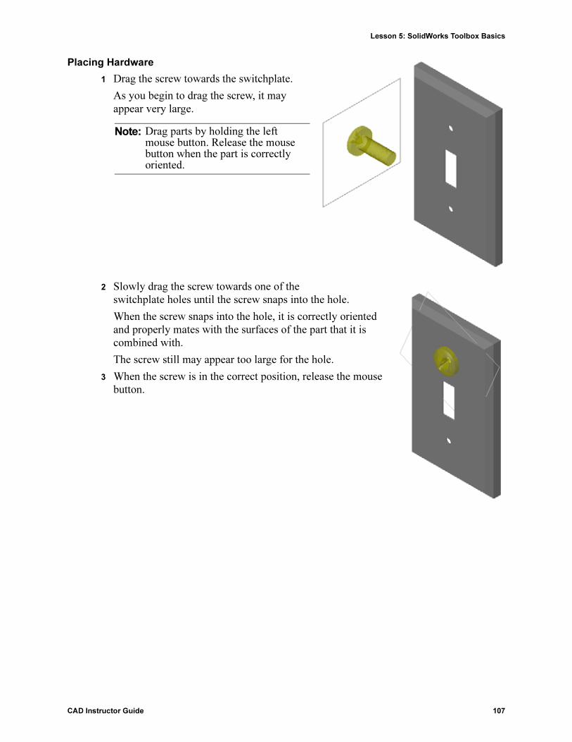
Placing Hardware
1 Drag the screw towards the switchplate.
As you begin to drag the screw, it may appear very large.
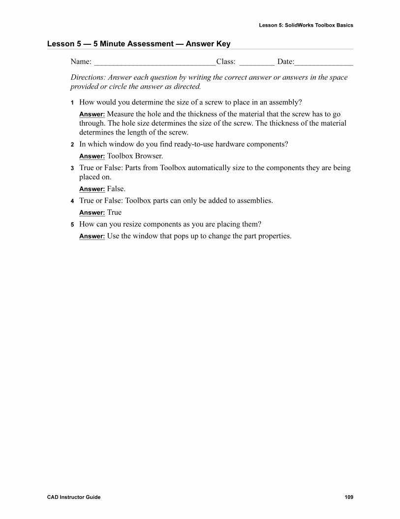
2 Slowly drag the screw towards one of the switchplate holes until the screw snaps into the hole.
When the screw snaps into the hole, it is correctly oriented and properly mates with the surfaces of the part that it is combined with.
The screw still may appear too large for the hole.
3 When the screw is in the correct position, release the mouse button.
Note: Drag parts by holding the left mouse button. Release the mouse button when the part is correctly oriented.

Lesson 5: SolidWorks Toolbox Basics
108 CAD Instructor Guide
Specifying the Properties of the Toolbox Part
After you release the mouse button, a PropertyManager appears.
1 If necessary, change the properties of the screw to match the holes. In this case, a #6-32 screw with 1” length works with these holes.
2 When you have completed the property changes, click OK .
The first screw is now placed in the first hole.
3 Repeat the process for the second hole.
You should not have to change any of the screw properties for the second screw. Toolbox remembers your last selection.
Both screws are now in the switchplate.
Lesson 5: SolidWorks Toolbox Basics
CAD Instructor Guide 109
Lesson 5 — 5 Minute Assessment — Answer Key
Name: _______________________________Class: _________ Date:_______________
Directions: Answer each question by writing the correct answer or answers in the space
provided or circle the answer as directed.
1 How would you determine the size of a screw to place in an assembly?
Answer: Measure the hole and the thickness of the material that the screw has to go through. The hole size determines the size of the screw. The thickness of the material determines the length of the screw.
2 In which window do you find ready-to-use hardware components?
Answer: Toolbox Browser.
3 True or False: Parts from Toolbox automatically size to the components they are being placed on.
Answer: False.
4 True or False: Toolbox parts can only be added to assemblies.
Answer: True
5 How can you resize components as you are placing them?
Answer: Use the window that pops up to change the part properties.

Lesson 5: SolidWorks Toolbox Basics
110 CAD Instructor Guide
Lesson 5 — 5 Minute Assessment REPRODUCIBLE
Name: _______________________________Class: _________ Date:_______________
Directions: Answer each question by writing the correct answer or answers in the space
provided or circle the answer as directed.
1 How would you determine the size of a screw to place in an assembly?
_____________________________________________________________________
_____________________________________________________________________
_____________________________________________________________________
2 In which window do you find ready-to-use hardware components?
_____________________________________________________________________
3 True or False: Parts from Toolbox automatically size to the components they are being placed on.
_____________________________________________________________________
4 True or False: Toolbox parts can only be added to assemblies.
_____________________________________________________________________
5 How can you resize components as you are placing them?
_____________________________________________________________________
_____________________________________________________________________

Lesson 5: SolidWorks Toolbox Basics
CAD Instructor Guide 111
Exercises and Projects — Bearing Block Assembly
Add bolts and washers to fasten the bearing rest to the bearing block.
Opening the Assembly
1 Open Bearing Block Assembly.
Bearing Block Assembly has Bearing Rest and Bearing Block as components.
In this exercise, you are going to bolt the bearing rest to the bearing block. The through holes in the bearing rest are designed to allow the bolts to pass through but not be loose. The holes in the bearing block are tapped holes. Tapped holes are threaded and specifically designed to act like nuts do. In other words, the bolt screws directly into the bearing block.
If you take a close look at the holes, you see that the holes in the bearing rest are larger than those of the bearing block. That is because the holes in the bearing block are represented with the amount of material needed for the creation of the screw threads. The screw threads are not visible. Threads are rarely shown in models.
Placing Washers
Washers have to be placed before the screws or bolts. You do not have to use washers every time you place screws. However, when you do intend to use washers, they must be placed before screws, bolts, or nuts so that the correct relationships can be established.
The washers mate with the surface of the part and the screw or bolt mates with the washer. Nuts also mate with washers.
2 Expand the Toolbox Browser icon in the Design Library Task Pane.
Lesson 5: SolidWorks Toolbox Basics
112 CAD Instructor Guide
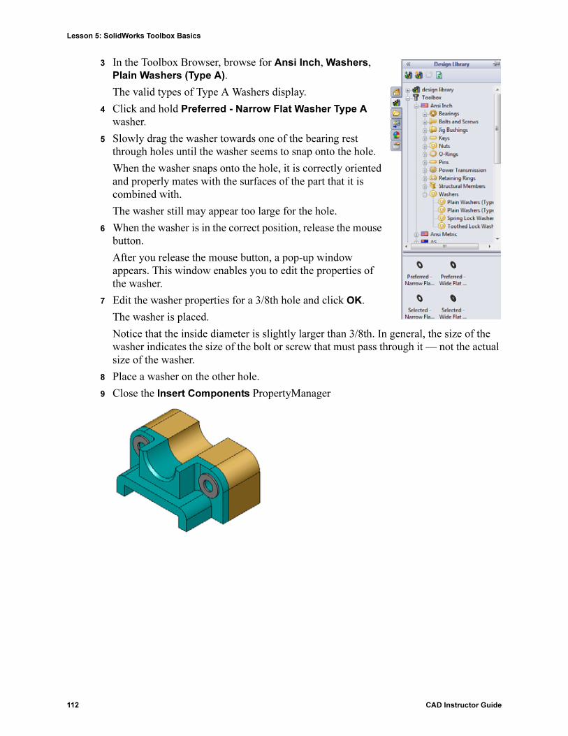
3 In the Toolbox Browser, browse for Ansi Inch, Washers, Plain Washers (Type A).
The valid types of Type A Washers display.
4 Click and hold Preferred - Narrow Flat Washer Type A washer.
5 Slowly drag the washer towards one of the bearing rest through holes until the washer seems to snap onto the hole.
When the washer snaps onto the hole, it is correctly oriented and properly mates with the surfaces of the part that it is combined with.
The washer still may appear too large for the hole.
6 When the washer is in the correct position, release the mouse button.
After you release the mouse button, a pop-up window appears. This window enables you to edit the properties of the washer.
7 Edit the washer properties for a 3/8th hole and click OK.
The washer is placed.
Notice that the inside diameter is slightly larger than 3/8th. In general, the size of the washer indicates the size of the bolt or screw that must pass through it — not the actual size of the washer.
8 Place a washer on the other hole.
9 Close the Insert Components PropertyManager

Lesson 5: SolidWorks Toolbox Basics
CAD Instructor Guide 113
Placing Screws
1 Select Ansi Inch, Bolts and Screws, and Machine Screws from Toolbox Browser.
2 Drag a Hex Screw to one of the washers that you placed earlier.
3 Snap the screw into place and release the mouse button.
A window appears with the properties for the hex screw.
4 Select a 3/8-24 screw of the appropriate length and click OK.
The first screw is placed. The screw establishes a mate relationship with the washer.
5 Place the second screw in the same way.
6 Close the Insert Components PropertyManager.
Thread Display
While fasteners such as bolts and screws are fairly detailed parts, they also very common ones. In general, bolts and screws are not the parts that you design. Instead you will use off-the-shelf hardware components. It is a well-established design practice to not draw all of the details of fasteners, but to specify their properties and show only an outline — or simplified — view of them.
The three display modes for bolts and screws are:
� Simplified — Represents the hardware with few details. This is the most common display. Simplified display shows the bolt or screw as if it were unthreaded.
Lesson 5: SolidWorks Toolbox Basics
114 CAD Instructor Guide
� Cosmetic — Represents some details of the hardware. Cosmetic display shows the barrel of the bolt or screw and represents the size of the threads as dashed lines.
� Schematic — Very detailed display which is rarely used. Schematic shows the bolt or screw as it really appears. This display is best used when designing a unique fastener or when specifying an uncommon one.
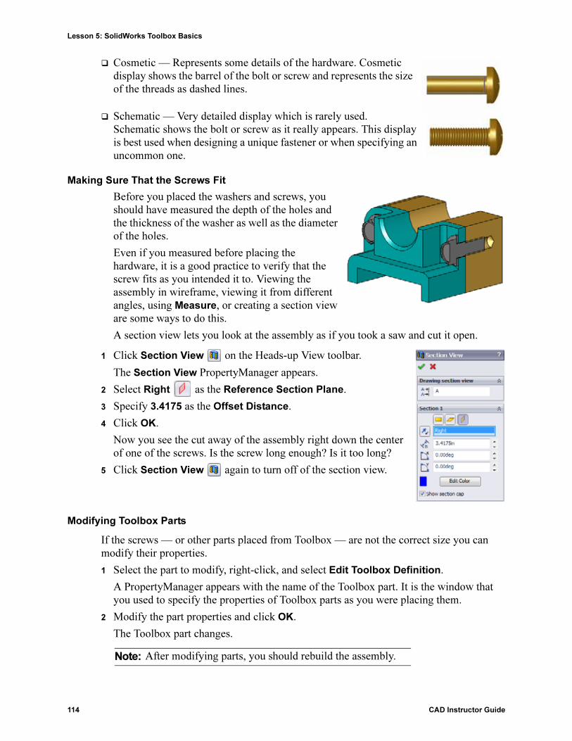
Making Sure That the Screws Fit
Before you placed the washers and screws, you should have measured the depth of the holes and the thickness of the washer as well as the diameter of the holes.
Even if you measured before placing the hardware, it is a good practice to verify that the screw fits as you intended it to. Viewing the assembly in wireframe, viewing it from different angles, using Measure, or creating a section view are some ways to do this.
A section view lets you look at the assembly as if you took a saw and cut it open.
1 Click Section View on the Heads-up View toolbar.
The Section View PropertyManager appears.
2 Select Right as the Reference Section Plane.
3 Specify 3.4175 as the Offset Distance.
4 Click OK.
Now you see the cut away of the assembly right down the center of one of the screws. Is the screw long enough? Is it too long?
5 Click Section View again to turn off of the section view.
Modifying Toolbox Parts
If the screws — or other parts placed from Toolbox — are not the correct size you can modify their properties.
1 Select the part to modify, right-click, and select Edit Toolbox Definition.
A PropertyManager appears with the name of the Toolbox part. It is the window that you used to specify the properties of Toolbox parts as you were placing them.
2 Modify the part properties and click OK.
The Toolbox part changes.
Note: After modifying parts, you should rebuild the assembly.

Lesson 5: SolidWorks Toolbox Basics
CAD Instructor Guide 115
More to Explore — Add Hardware to an Assembly
In the previous exercise you used Toolbox to add washers and screws to an assembly. In that assembly, the screws went into blind holes. In this exercise, add washers, lock washers, screws, and nuts to an assembly.
1 Open Bearing Plate Assembly.
2 Add the washers (Preferred - Narrow Flat
Washer Type A parts) to the through holes on the bearing rest first. The holes are 3/8th diameter.
3 Add the lock washers (Regular Spring Lock Washer parts) to the far side of the plate next.
4 Add 1-inch machine screws with a pan cross head. Snap these to the washers on the bearing rest.
5 Add hex nuts (Hex Nut parts). Snap these to the lock washers.
6 Use the techniques that you have learned to verify that the hardware is the correct size for this assembly.

Lesson 5: SolidWorks Toolbox Basics
116 CAD Instructor Guide
Lesson 5 Vocabulary Worksheet — Answer Key
Name: _______________________________Class: _________ Date:_______________
Fill in the blanks with the words that are defined by the clues.
1 View that lets you look at the assembly as if you took a saw and cut it open: Section
view
2 Type of hole that allows a screw or bolt to be screwed directly into it: Tapped hole
3 Common design practice that represents the screws and bolts showing outlines and few details: Simplified
4 Method for moving a Toolbox part from the Toolbox Browser to the assembly: Drag
and drop
5 Area of Design Library Task Pane that contains all available Toolbox parts: Toolbox
Browser
6 A file where you where you combine parts together: Assembly
7 Hardware — such as screws, nuts, washers, and lock washers — that you can select from the Toolbox Browser: Toolbox parts
8 Type of hole that allows a screw or bolt into it, but is not tapped: Through hole
9 Properties — such as size, length, thread length, display type — that describe a Toolbox part: Toolbox definition

Lesson 5: SolidWorks Toolbox Basics
CAD Instructor Guide 117
Lesson 5 Vocabulary Worksheet REPRODUCIBLE
Name: _______________________________Class: _________ Date:_______________
Fill in the blanks with the words that are defined by the clues.
1 View that lets you look at the assembly as if you took a saw and cut it open:_________
_____________________________________________________________________
2 Type of hole that allows a screw or bolt to be screwed directly into it: ______________
_____________________________________________________________________
3 Common design practice that represents the screws and bolts showing outlines and few details:________________________________________________________________
4 Method for moving a Toolbox part from the Toolbox Browser to the assembly: ______
_____________________________________________________________________
5 Area of Design Library Task Pane that contains all available Toolbox parts: _________
_____________________________________________________________________
6 A file where you where you combine parts together:____________________________
7 Hardware — such as screws, nuts, washers, and lock washers — that you can select from the Toolbox Browser: _______________________________________________
8 Type of hole that allows a screw or bolt into it, but is not tapped:__________________
_____________________________________________________________________
9 Properties — such as size, length, thread length, display type — that describe a Toolbox part: __________________________________________________________

Lesson 5: SolidWorks Toolbox Basics
118 CAD Instructor Guide
Lesson 5 Quiz — Answer Key
Name: _______________________________Class: _________ Date:_______________
Directions: Answer each question by writing the correct answer or answers in the space
provided or circle the answer as directed.
1 How do you establish a mate relationship between a Toolbox part and the part it is being placed on?
Answer: The mate relationship is established when the Toolbox part snaps to the other part. You do not have to explicitly define the relationship.
2 What does Edit Toolbox Definition enable you to change?
Answer: Toolbox part properties such as size, thread display, and length.
3 If you need a washer for a 3/8th diameter screw or bolt, is the inside dimension of the washer also 3/8th? If not, why not?
Answer: The inside diameter of washers is slightly larger than the outside dimension of the screw or bolt that it is combined with. This allows the screw or bolt to pass through it.
4 How would you determine the correct length of a machine screw that fastens two parts using a washer, lock washer, and nut?
Answer: Measure the thickness of both parts, the washer, the lock washer, and nut. Use a screw that is the next size longer so that the threads of the screw engage all of the threads of the nut.
5 How do you select a lock washer from Toolbox?
Answer: In the Toolbox Browser, select Ansi Inch (or other standard), Washers, and Spring Lock Washers.
6 True or False. To place a Toolbox part you have to specify the exact X, Y, Z coordinates.
Answer: False.
7 How do you specify the location of a Toolbox part?
Answer: You place Toolbox parts by dragging them and dropping them in the assembly.
8 How would you measure hole size?
Answer: Use either the Measure or Dimension commands.
9 True or False. Screw threads are always displayed in Schematic mode — showing all details.
Answer: True

Lesson 5: SolidWorks Toolbox Basics
CAD Instructor Guide 119
Lesson 5 Quiz REPRODUCIBLE
Name: _______________________________Class: _________ Date:_______________
Directions: Answer each question by writing the correct answer or answers in the space
provided or circle the answer as directed.
1 How do you establish a mate relationship between a Toolbox part and the part it is being placed on?_____________________________________________________________________________________________________________________________
2 What does Edit Toolbox Definition enable you to change? ___________________________________________________________________________________________
3 If you need a washer for a 3/8th diameter screw or bolt, is the inside dimension of the washer also 3/8th? If not, why not? ______________________________________________________________________________________________________________
4 How would you determine the correct length of a machine screw that fastens two parts using a washer, lock washer, and nut? ____________________________________________________________________________________________________________
5 How do you select a lock washer from Toolbox? ___________________________________________________________________________________________________
6 True or False. To place a Toolbox part you have to specify the exact X, Y, Z coordinates.____________________________________________________________
7 How do you specify the location of a Toolbox part? _________________________________________________________________________________________________
8 How would you measure hole size? ______________________________________________________________________________________________________________
9 True or False. Screw threads are always displayed in Schematic mode — showing all details.________________________________________________________________

Lesson 5: SolidWorks Toolbox Basics
120 CAD Instructor Guide
Lesson Summary
� Toolbox provides ready-to-use parts — such as bolts and screws.
� Toolbox parts are placed by dragging and dropping them in assemblies.
� You can edit the property definitions of Toolbox parts.
� Holes created with the hole wizard are easy to match with properly-sized hardware from Toolbox.

Lesson 5: SolidWorks Toolbox Basics
CAD Instructor Guide 121
Thumbnail Images of PowerPoint Slides
The following thumbnail images, arranged left to right, show the PowerPoint slides provided with this lesson.
1
�© D
assa
ult S
ystèm
es �
Confi
denti
alInf
orm
ation
�
Instructor�s Guide to Teaching SolidWorks Software Lesson 5
School’s NameTeacher’s Name
Date
2
�© D
assa
ult S
ystèm
es �
Confi
denti
alInf
orm
ation
�
What is Toolbox?
� Ready-to-use standard parts such as bolts, screws, washers, lock washers, and so forth.
� Eliminates the need to model most fasteners and many other standard parts.
� Easy drag-and-drop placement.
3
�© D
assa
ult S
ystèm
es �
Confi
denti
alInf
orm
ation
�
Toolbox Browser
� Browser containing libraries of ready-to-use components.
� Click to access Toolbox Browser.
� Contains libraries of ready-to-use parts.
4
�© D
assa
ult S
ystèm
es �
Confi
denti
alInf
orm
ation
�
Easy Drag-and-Drop Placement
� Drag from Toolbox Browser� Snap to assembly
5
�© D
assa
ult S
ystèm
es �
Confi
denti
alInf
orm
ation
�
Mate Relationships Defined at Placement
� When the Toolbox part snaps to the assembly, the mate relationship between the Toolbox part and the other part is established.
� When using washers, place them first. Subsequent hardware �like screws and nuts � mate to the washers.
6
�© D
assa
ult S
ystèm
es �
Confi
denti
alInf
orm
ation
�
Standard Hardware Matches - Standard Holes
� Hardware placed on holes created using the Hole Wizard is appropriately sized.
� Standard sized parts help to keep your designs realistic.

Lesson 5: SolidWorks Toolbox Basics
122 CAD Instructor Guide
7
�© D
assa
ult S
ystèm
es �
Confi
denti
alInf
orm
ation
�
Specifying Toolbox Part Properties
Change part properties to customize the hardware to your design.� Specify the properties as you are
placing the part.� Ability to change the properties after
the part is placed.
8
�© D
assa
ult S
ystèm
es �
Confi
denti
alInf
orm
ation
�
Thread Display
� Simplified � Represents the hardware with few details. Most common display.
� Cosmetic � Represents some details of the hardware.
� Schematic � Very detailed display which is used for unusual or custom designed hardware.
9
�© D
assa
ult S
ystèm
es �
Confi
denti
alInf
orm
ation
�
Supported Standards
Toolbox supports international standards� ANSI� BSI� CISC� DIN� ISO� JIS
10
�© D
assa
ult S
ystèm
es �
Confi
denti
alInf
orm
ation
�
Libraries from Leading Manufacturers
Toolbox contains standard parts libraries from leading manufacturers such as:� PEM®� Torrington®� Truarc®� SKF®� Unistrut®