lesson 17: synchronous machines - siu · 2016-01-15 · lesson 17: synchronous machines et 332b ac...
TRANSCRIPT

1/15/2016
1
Lesson 17: Synchronous
Machines ET 332b
Ac Motors, Generators and Power Systems
1 Lesson 17_et332b.pptx
Learning Objectives
Lesson 17_et332b.pptx 2
After this presentation you will be able to:
Explain how synchronous machines operate.
Draw the per phase circuit model of a synchronous
machine.
Write and utilize the power equations for synchronous
machines.
Use machine equations to determine a machines
operation point and power
Compute motor torques

1/15/2016
2
Synchronous Machines
Lesson 17_et332b.pptx 3
Synchronous Motors – Convert electrical power into
mechanical power. They operate at a constant speed
Synchronous generator (Alternator) - Convert
mechanical power into electrical power (3-phase).
Constant speed of mechanical drive gives constant
frequency ac
Basic Construction of Synchronous
Machines
Lesson 17_et332b.pptx 4
Stationary part of machine
called the armature. Similar
to induction motor stator
Rotating part of machine is
electromagnet energized by a
dc source and called the field
1/15/2016
3
Operational Theory for
Synchronous Machines
Lesson 17_et332b.pptx 5
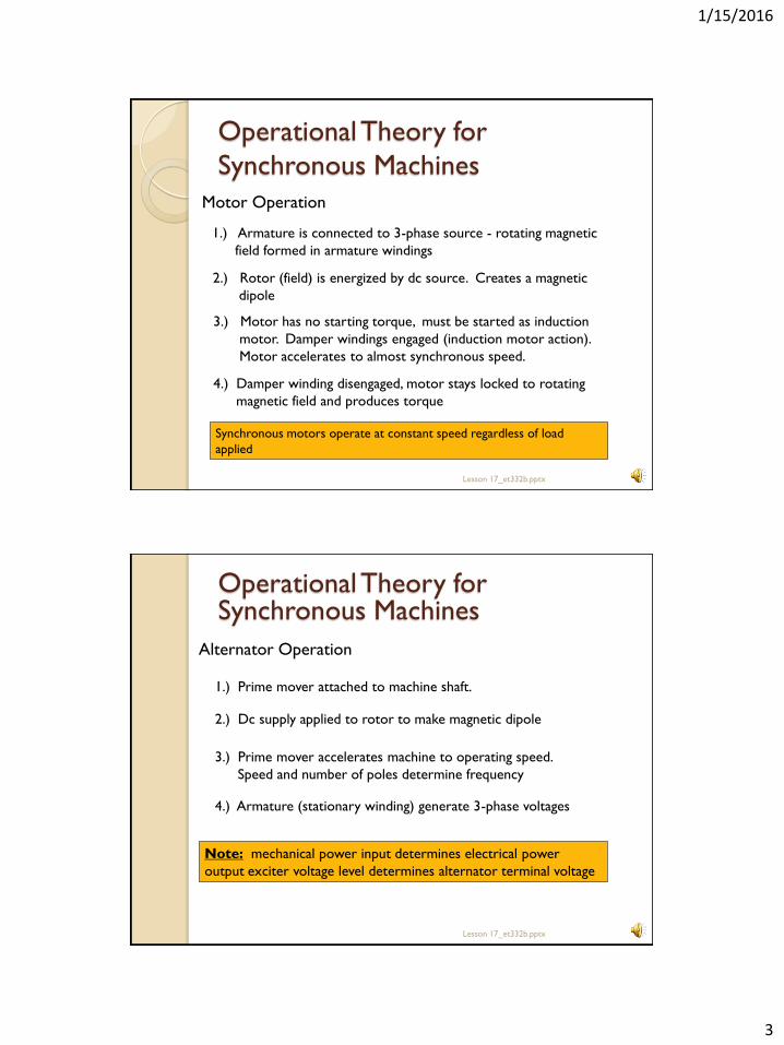
4.) Damper winding disengaged, motor stays locked to rotating
magnetic field and produces torque
Motor Operation
1.) Armature is connected to 3-phase source - rotating magnetic
field formed in armature windings
2.) Rotor (field) is energized by dc source. Creates a magnetic
dipole
3.) Motor has no starting torque, must be started as induction
motor. Damper windings engaged (induction motor action).
Motor accelerates to almost synchronous speed.
Synchronous motors operate at constant speed regardless of load
applied
Lesson 17_et332b.pptx 6
Operational Theory for Synchronous Machines
Alternator Operation
4.) Armature (stationary winding) generate 3-phase voltages
1.) Prime mover attached to machine shaft.
2.) Dc supply applied to rotor to make magnetic dipole
3.) Prime mover accelerates machine to operating speed.
Speed and number of poles determine frequency
Note: mechanical power input determines electrical power
output exciter voltage level determines alternator terminal voltage
1/15/2016
4
Synchronous Motor Operation
Lesson 17_et332b.pptx 7
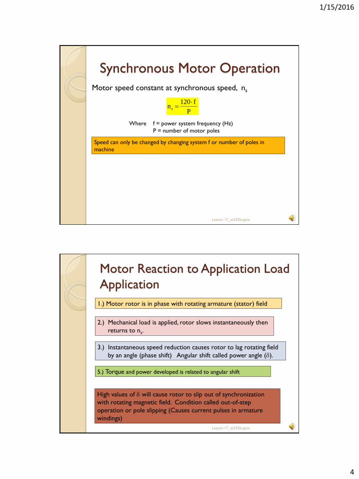
Motor speed constant at synchronous speed, ns
P
f120ns
Where f = power system frequency (Hz)
P = number of motor poles
Speed can only be changed by changing system f or number of poles in
machine
Motor Reaction to Application Load
Application
Lesson 17_et332b.pptx 8
5.) Torque and power developed is related to angular shift
1.) Motor rotor is in phase with rotating armature (stator) field
2.) Mechanical load is applied, rotor slows instantaneously then
returns to ns.
3.) Instantaneous speed reduction causes rotor to lag rotating field
by an angle (phase shift) Angular shift called power angle (d).
High values of d will cause rotor to slip out of synchronization
with rotating magnetic field. Condition called out-of-step
operation or pole slipping (Causes current pulses in armature
windings)
1/15/2016
5
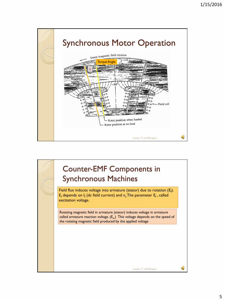
Synchronous Motor Operation
Lesson 17_et332b.pptx 9
d
Torque Angle
Counter-EMF Components in
Synchronous Machines
Lesson 17_et332b.pptx 10
Field flux induces voltage into armature (stator) due to rotation (Ef).
Ef depends on If (dc field current) and ns The parameter Ef , called
excitation voltage.
Rotating magnetic field in armature (stator) induces voltage in armature
called armature reaction voltage. (Ear) This voltage depends on the speed of
the rotating magnetic field produced by the applied voltage
1/15/2016
6
Per Phase Circuit Model
Lesson 17_et332b.pptx 11
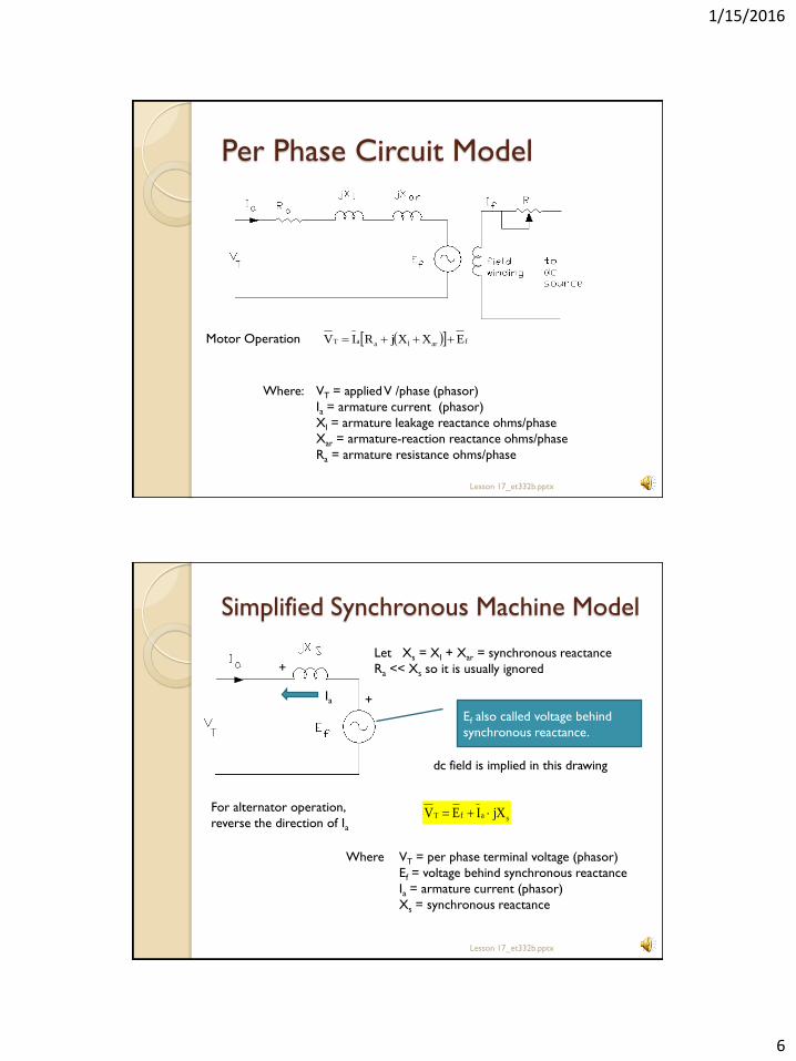
Motor Operation
Where: VT = applied V /phase (phasor)
Ia = armature current (phasor)
Xl = armature leakage reactance ohms/phase
Xar = armature-reaction reactance ohms/phase
Ra = armature resistance ohms/phase
farlaaT EXXjRIV
Simplified Synchronous Machine Model
Lesson 17_et332b.pptx 12
Let Xs = Xl + Xar = synchronous reactance
Ra << Xs so it is usually ignored
For alternator operation,
reverse the direction of Ia
Ia
Ef also called voltage behind
synchronous reactance.
dc field is implied in this drawing
safT jXIEV
Where VT = per phase terminal voltage (phasor)
Ef = voltage behind synchronous reactance
Ia = armature current (phasor)
Xs = synchronous reactance
+
+

1/15/2016
7
Power Transfer in Synchronous
Machines
Lesson 17_et332b.pptx 13
d
)sin(Ef d
qi
)cos(XI isa q
XIa
Ef
From phasor diagram above
)cos(XI)sin(E isaf qd
Power Transfer In Synchronous
Machines
Lesson 17_et332b.pptx 14
Multiplying the equation from the phasor diagram by VT and dividing
both sides by Xs gives power/phase.
)cos(IV)sin(X
EV
iaT
s
fT
qd
Where: qi = machine power factor.
Total 3-phase power is
)cos(IV3P
)sin(X
EV3P
iaTin
s
fT
in
q
d
In terms of input quantities
In terms of machine quantities
1/15/2016
8
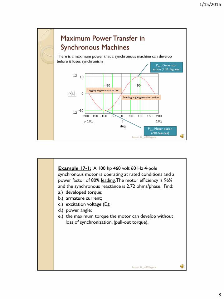
Maximum Power Transfer in
Synchronous Machines
Lesson 17_et332b.pptx 15
There is a maximum power that a synchronous machine can develop
before it loses synchronism
200 150 100 50 0 50 100 150 200
10
0
1012
12
P d
180180
9090
d
degPmax Motor action
(-90 degrees)
Pmax Generator
action (+90 degrees)
Lagging angle-motor action
Leading angle-generator action
Lesson 17_et332b.pptx 16
Example 17-1: A 100 hp 460 volt 60 Hz 4-pole
synchronous motor is operating at rated conditions and a
power factor of 80% leading. The motor efficiency is 96%
and the synchronous reactance is 2.72 ohms/phase. Find:
a.) developed torque;
b.) armature current;
c.) excitation voltage (Ef);
d.) power angle;
e.) the maximum torque the motor can develop without
loss of synchronization. (pull-out torque).
1/15/2016
9
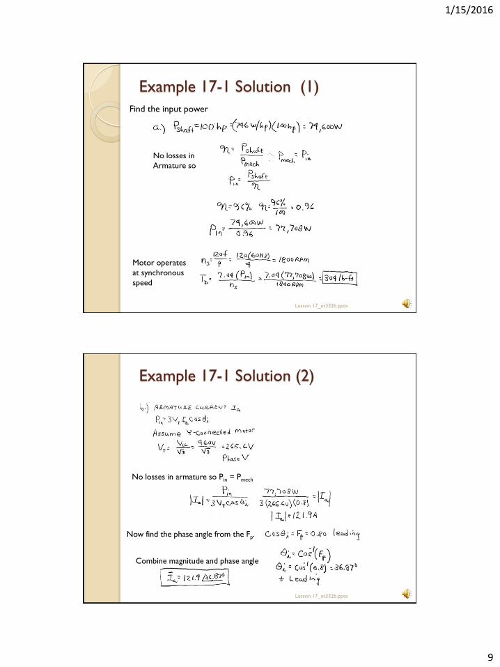
Example 17-1 Solution (1)
Lesson 17_et332b.pptx 17
Find the input power
No losses in
Armature so
Motor operates
at synchronous
speed
Lesson 17_et332b.pptx 18
Example 17-1 Solution (2)
No losses in armature so Pin = Pmech
Now find the phase angle from the Fp.
Combine magnitude and phase angle
1/15/2016
10
Lesson 17_et332b.pptx 19
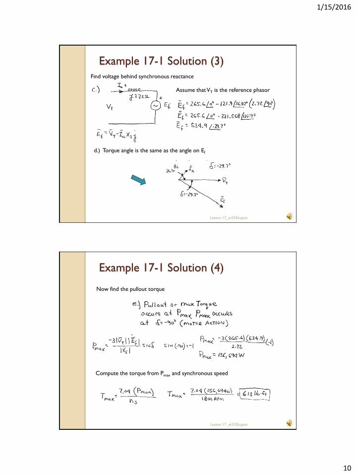
Example 17-1 Solution (3) Find voltage behind synchronous reactance
Assume that VT is the reference phasor
d.) Torque angle is the same as the angle on Ef
Lesson 17_et332b.pptx 20
Example 17-1 Solution (4)
Now find the pullout torque
Compute the torque from Pmax and synchronous speed

1/15/2016
11
END LESSON 17
ET 332b
Ac Motors, Generators and Power Systems
Lesson 17_et332b.pptx 21