lehi city design standards and public … · this book contains general design standards and public...
TRANSCRIPT

LEHI CITY DESIGN STANDARDS
AND PUBLIC IMPROVEMENT
SPECIFICATIONS
2016
LEHI CITY CORPORATION LEHI, UTAH

i
PREFACE
The standards and requirements contained herein shall apply to all development and/or construction within the corporate limits of Lehi City. It is incumbent upon any person developing property and/or constructing improvements within Lehi City to acquaint himself with these Standards and subsequent changes. These standards have been approved by the City Council of Lehi City. Changes to these standards shall be approved by the City Council. THIS DOCUMENT AND ANY ILLUSTRATIONS HEREON ARE PROVIDED AS STANDARD CONSTRUCTION SPECIFICATIONS AND DETAILS WITHIN LEHI CITY. DEVIATION FROM THIS DOCUMENT REQUIRES APPROVAL OF LEHI CITY. LEHI CITY CANNOT BE HELD LIABLE FOR MISUSE OR CHANGES REGARDING THIS DOCUMENT.

ii

iii
TABLE OF CONTENTS PREFACE CHAPTER 1 GENERAL DEVELOPMENT REQUIREMENTS
Section 1.01 General 1-1 Section 1.02 Engineering and Surveying Requirements 1-1 Section 1.03 Electrical Design & Specification Requirements 1-1
CHAPTER 2 DESIGN STANDARDS
Section 2.01 General 2-1 Section 2.02 Streets 2-1 Section 2.03 Street Alignment And Pavement Section Standards 2-2 Figure 2-1, Lehi City Pavement Design Chart 2-3 Vertical Alignment Criteria 2-4 Horizontal Alignment Criteria 2-5 Section 2.04 General Street Design Standards 2-6 Section 2.05 Fencing & Landscaping Standards for Arterial and/or Other Streets as Applicable 2-7 Section 2.06 Blocks 2-10 Section 2.07 Lot Requirements 2-11 Section 2.08 Easements 2-11 Section 2.09 Water Systems 2-12 Section 2.10 Fire Hydrants 2-12 Section 2.11 Sewage System 2-13 Section 2.12 Drainage System Plan 2-14 Section 2.13 Best Management Practices 2-17 Section 2.14 Signs 2-18 Section 2.15 Lot Corners 2-18 Section 2.16 Dedications 2-18 Section 2.17 Trails 2-19 Section 2.18 Exceptions 2-20 Section 2.19 Sharing Cost of Improvements 2-21
CHAPTER 3 GENERAL CONSTRUCTION REQUIREMENTS
Section 3.01 General 3-1 Section 3.02 Requests for Inspection 3-2 Section 3.03 Erosion & Sedimentation Control Plan 3-2 Section 3.04 As-Built File Requirements 3-2 Section 3.05 Construction Completion Inspection 3-3 Section 3.06 Guarantee of Work 3-3 Section 3.07 Building Permits 3-3 Section 3.08 Construction Traffic Control 3-4 Section 3.09 Fire Department Access 3-4 Section 3.10 Materials Testing 3-4

iv
CHAPTER 4 EARTHWORK Section 4.01 General 4-1 Section 4.02 Excavation Permit Requirements 4-1 Section 4.03 Excavation for Structures 4-1 Section 4.04 Backfill Around Structures 4-1 Section 4.05 Construction of Embankments & Fills 4-2 Section 4.06 Compacting Earth Materials 4-2 Section 4.07 Slopes 4-3
CHAPTER 5 PORTLAND CEMENT CONCRETE
Section 5.01 General 5-1 Section 5.02 Materials 5-1 Section 5.03 Concrete Mix 5-2 Section 5.04 Forms 5-3 Section 5.05 Joints 5-3 Section 5.06 Reinforcing Steel Placement 5-4 Section 5.07 Preparations 5-5 Section 5.08 Concrete Mixing 5-5 Section 5.09 Layout 5-6 Section 5.10 Depositing 5-6 Section 5.11 Placing Concrete in Cold Weather 5-6 Section 5.12 Finishing 5-7 Section 5.13 Curing & Protection 5-7 Section 5.14 Removal of Forms 5-8 Section 5.15 Concrete Delivery Tickets 5-8 Section 5.16 Concrete Testing 5-9
CHAPTER 6 ASPHALT PAVING
Section 6.01 General 6-1 Section 6.02 Road Sub-grade Preparation 6-1 Section 6.03 Base Course 6-2 Section 6.04 Bituminous Surface Course 6-3 Section 6.05 Full Depth Asphalt 6-4 Section 6.06 Construction Methods & Equipment 6-4 Section 6.07 Spreading & Compaction 6-4 Section 6.08 Weather Limitations 6-5 Section 6.09 Flagging 6-5 Section 6.10 Trench Settlement Limitations 6-6
CHAPTER 7 EXCAVATION AND BACKFILL FOR PIPELINES
Section 7.01 General 7-1 Section 7.02 Control of Groundwater 7-1 Section 7.03 Excavation for Pipeline 7-1 Section 7.04 Foundation Stabilization 7-2 Section 7.05 Blasting 7-3 Section 7.06 Sheeting, Bracing & Shoring of Excavations 7-3

v
Section 7.07 Access to Trenches 7-3 Section 7.08 Backfilling 7-3 Section 7.09 Backfilling of Fire Lines 7-4 Section 7.10 Consolidation of Backfill 7-5 Section 7.11 Compaction of Backfill (Top 4 feet of Trench) 7-5 Section 7.12 Imported Select Backfill Material 7-6 Section 7.13 Restoration of Surface Improvements 7-6 Section 7.14 Disposal of Excess Materials 7-6 Section 7.15 Location of Stub Pipes 7-7
CHAPTER 8 CULINARY AND IRRIGATION WATER LINES
Section 8.01 General 8-1 Section 8.02 Concrete Thrust Blocking 8-1 Section 8.03 Pipe Laying 8-1 Section 8.04 Ductile Iron Pipe 8-2 Section 8.05 Polyvinyl Chloride Pipe 8-4 Section 8.06 Valves 8-6 Section 8.07 Culinary Blow Offs 8-6 Section 8.08 Fire Hydrants 8-7 Section 8.09 Post Indicator Valve 8-8 Section 8.10 Service Laterals 8-8 Section 8.11 Irrigation Service Valves and Boxes 8-9 Section 8.12 Culinary Water Line Construction near Sewer or Wastewater Lines (Applicable Public Health Department Criteria) 8-9 Section 8.13 Testing & Flushing Waterlines 8-10 Section 8.14 Testing of Underground Fire Service Mains 8-11 Section 8.15 Disinfection of Culinary Waterlines 8-12 Section 8.16 General Contractor Guidelines to meet the Above Standard 8-13 Section 8.17 Cross Connection Control and Back Flow Prevention 8-14 Section 8.18 Culinary Water and Pressure Irrigation Meters and Meter Setters 8-15
CHAPTER 9 SEWER/ STORM DRAIN/ IRRIGATION LINES
Section 9.01 General 9-1 Section 9.02 Building Subsurface Drains (Perimeter, Etc.) 9-1 Section 9.03 Irrigation Lines 9-1 Section 9.04 Pipe Laying 9-1 Section 9.05 Grades 9-2 Section 9.06 Concrete Sewer, Storm Drain or Irrigation Pipe 9-2 Section 9.07 Reinforced Concrete Pipe 9-2 Section 9.08 Plastic Sewer Pipe 9-2 Section 9.09 Corrugated High Density Polyethylene Pipe 9-3 Section 9.10 Storm Drain Inlets and Combination Boxes 9-4 Section 9.11 Manholes 9-4 Section 9.12 Cleaning and Testing Sanitary Sewer, Storm Drainage and Irrigation Lines and Manholes 9-7

vi
CHAPTER 10 LANDSCAPING AND SPRINKLING SYSTEMS
Section 10.01 General Description 10-1 Section 10.02 General Conditions 10-1 Section 10.03 Excavation and Backfill 10-3 Section 10.04 Pipe and Tube 10-3 Section 10.05 Sprinkler Heads, Gate Valves and Quick Couplers 10-4 Section 10.06 Irrigation Controller 10-5 Section 10.07 Electric Remote-Control Valves 10-5 Section 10.08 Connection 10-5 Section 10.09 Planting Specifications 10-6 Section 10.10 Scope of Work 10-6 Section 10.11 Drawings and Specifications 10-6 Section 10.12 Obstructions Below Ground 10-6 Section 10.13 Spacing 10-7 Section 10.14 Plants to be Furnished 10-7 Section 10.15 Substitutions 10-7 Section 10.16 Finish Grading and Soil Preparation 10-8 Section 10.17 Planting 10-8 Section 10.18 Staking 10-10 Section 10.19 Maintenance 10-10 Section 10.20 Inspections and Procedures 10-11
CHAPTER 11 RESTORATION OF SURFACE IMPROVEMENTS
Section 11.01 General 11-1 Section 11.02 Gravel Road Repair 11-1 Section 11.03 Asphalt Surface Repair 11-1 Section 11.04 Concrete Surfaces 11-2 Section 11.05 Irrigation Ditches 11-2
CHAPTER 12 BEST MANAGEMENT PRACTICES
Section 12.01 General 12-1 Section 12.02 Storm Water Quality Criteria 12-1 Section 12.03 Contents of Storm Water Pollution Prevention Plan 12-3 Section 12.04 Contents of Post Construction Storm Water Pollution Prevention Plan 12-4 Section 12.05 Review Procedures for Storm Water Pollution Prevention Plan and Post Construction Storm Water Pollution Prevention Plan 12-6 Section 12.06 Conclusion 12-6

vii
STANDARD DETAILS Street Intersection & Utility Location Road 1 Street Cross Sections & Utility Locations Road 2 Curbs at Unequal Elevations Road 3 Rural Street Cross Section and Utility Locations Road 4 Curb, Gutter and Sidewalk Road 5 ADA Ramp Planter Strip (At Intersection) Road 6 ADA Ramp Combination Curb, Gutter & Sidewalk (At Intersection) Road 7 ADA Ramp Combination Curb, Gutter &Sidewalk (Mid Block) Road 8 ADA Ramp Planter Strip (Mid Block) Road 9 Radius Drive Approach Road 10 Flared Drive Approach Road 11 Cul-De-Sac Road 12 Knuckle Road 13 Temporary Turnaround and Access Roads Road 14 Fencing & Planter Strip Improvements (Along Limited Access Areas) Road 15 Half Width Street Cross Section Road 16 Concrete Replacement Criteria Road 17 Utility Trenching Water 1 Fire Hydrant Water 2 Blow-off Water 3 Valve Box Water 4 Thrust Blocking Water 5 Culinary Service Connection Water 6 Concrete Meter Box Water 7 Pressure Irrigation Service Connection Water 8 Post Indicator Valve Water 9 Typical Service, Hydrant & Blow-off Locations Water 10 Typical Fire Riser Details Water 11 Remote Fire Department Connection Water 12 Backflow Prevention Water 13 Casing Details Water 14 Line Manhole (Sewer & Storm Drain) Sewer/Drain 1 Junction Manhole (Sewer & Storm Drain) Sewer/Drain 2 Sewer/Storm Drain External Drop Manhole Detail Sewer/Drain 3 Sewer/Storm Drain Internal Drop Manhole Detail Sewer/Drain 4 Temporary Sewer Main Cleanout Sewer/Drain 5 Sewer Lateral Detail Sewer/Drain 6 Drain Clean-out Box Sewer/Drain 7 Inlet Box Sewer/Drain 8 Combo Box Detail Sewer/Drain 9 Storm Water Sump Sewer/Drain 10 Building Subsurface Drains Sewer/Drain 11 Headwall Detail Sewer/Drain 12

viii
Bicycle/Pedestrian Shared Use Trail Trail 1 Bicycle/Pedestrian & Equestrian Shared Use Trail Trail 2 Bicycle/Pedestrian & Equestrian Shared Use Trail Along Arterial Road Trail 3 Trash Enclosure Trash 1 Tree Planting & Staking Detail Landscape 1 Sprinkler Controller Box Detail Landscape 2 Rotor Pop-up Detail Landscape 3 Sprinkler Valve Assembly Detail Landscape 4 Irrigation Control Valve Detail Landscape 5 Hose Bib Yard Hydrant Landscape 6 Trench Details Landscape 7

1 - 1
CHAPTER 1 GENERAL DEVELOPMENT REQUIREMENTS SECTION 1.01 GENERAL This book contains general design standards and public improvement specifications for incorporation into all development projects within the boundaries of Lehi City. While these standards and specifications are generally intended for general subdivision and commercial site planning and design, they are also recommended for private developments and individual homeowners. This document is intended to be utilized with the Lehi City Development Code in the preparation of development plans for Lehi City. To the degree that this document is found to conflict with the Lehi City Development Code, the stricter standard shall govern. All standards contained herein are intended to establish minimum requirements and are subject to the interpretation of the Lehi City Engineer, or the Assistant Lehi City Engineer when approved to act for the Lehi City Engineer, on a case by case basis. SECTION 1.02 ENGINEERING AND SURVEYING REQUIREMENTS All engineering work in the development process in Lehi City must be done by or under the direction of a licensed professional engineer licensed to practice in the State of Utah or as allowed by the Utah Department of Licensing. All surveying and platting of property must be done by or under the direction of a registered land surveyor licensed to practice in the State of Utah. All documents submitted for City review shall be stamped and signed by said engineer or land surveyor in accordance with the procedures of the Utah State Board for Professional Registration. SECTION 1.03 ELECTRICAL DESIGN & SPECIFICATION REQUIREMENTS All electrical facilities shall be installed as per the current design specification requirements set forth by the current edition of the Lehi City Power Department Electrical Requirements & Standards Manual.
2 - 1
CHAPTER 2 DESIGN STANDARDS SECTION 2.01 GENERAL Preservation of terrain: The design and construction of subdivisions shall preserve, insofar as it is possible, the natural terrain, natural drainage, existing topsoil, trees and vegetation.
Critical lands: Critical environment lands and lands subject to hazardous conditions such as landslides, mudflows, ground subsidence, shallow water table, and floods shall be identified and shall not be subdivided until the hazards have been eliminated or evidence submitted that said hazards will be eliminated by the development and construction plans. The Standard Details Section of the Specifications depicts the basic design standards outlined in this section. Design Standards: The design of the preliminary and final plans to the subdivision in relation to streets, blocks, lots, open spaces and other design factors shall be in harmony with the following design standards. SECTION 2.02 STREETS
A. All streets in and adjacent to the subdivision must conform to the major street master plan of the city.
B. The alignment and width of all through streets shall be preserved unless unusual
topographical conditions make a modification advisable. Where the Planning Commission determines that it is desirable to provide for street access to adjoining property in order to provide for an orderly development of a street system, proposed streets shall be extended by dedication to the boundary of such property.
C. Where a large subdivision abuts upon a major thoroughfare, the Commission may
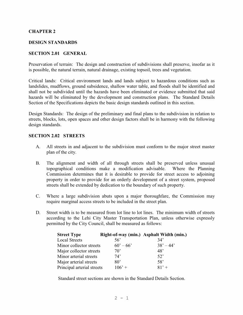
require marginal access streets to be included in the street plan. D. Street width is to be measured from lot line to lot lines. The minimum width of streets
according to the Lehi City Master Transportation Plan, unless otherwise expressly permitted by the City Council, shall be measured as follows:
Street Type Right-of-way (min.) Asphalt Width (min.) Local Streets 56’ 34’ Minor collector streets 60’ – 66’ 38’ – 44’ Major collector streets 70’ 48’ Minor arterial streets 74’ 52’ Major arterial streets 80’ 58’ Principal arterial streets 106’ + 81’ +
Standard street sections are shown in the Standard Details Section.

2 - 2
E. Cul-de-sacs (dead-end streets designed to be permanently closed to through traffic) shall be not longer than four hundred (400) feet to the beginning of the turnaround. Each cul-de-sac must be terminated by a turnaround of not less than one hundred (100) feet diameter, measured to the lip of curb lines. Partial cul-de-sac bulbs are allowable where deemed appropriate by the Planning Commission and/or City Council. If surface water drainage is into the turnaround, due to the grade of the street, necessary catch basins and drainage easements shall be provided. Temporary cul-de-sacs shall be as shown in the attached Design Drawings.
F. Streets shall intersect each other as near as possible at right angles. In no case shall the
deviation from 90 degrees be more than +/- 15 degrees. G. Street centerline offsets of less than one hundred and fifty (150) feet shall not be
allowed except where specifically authorized by the City Engineer. Major streets such as through collectors, etc. require a street centerline offset of three hundred and fifty (350) feet or more as determined by the City Engineer. City streets may be offset at an intersection up one half of the paved portion of the street as allowed by the City Engineer.
H. All arterial roads shall be as approved or designed by the City Engineer and shall
incorporate the following; limited access control along roadway restricting front facing lots, without City Council variance, widths as required based on projected traffic volumes and road classification in the Master Plan.
I. All subdivisions shall abut on and have access to at least one paved public street and as
a minimum, allowance for one or more future accesses as developments adjacent hereto proceed. If the development exceeds 50 equivalent residential units, a second paved city street must be incorporated in the subdivision unless otherwise approved by the Planning Commission.
J. Pavement design (asphalt, base and sub-base) shall conform to the requirements
outlined in Figure 2-1 or an alternate design by a Registered Geotechnical Engineer, licensed within the State of Utah, as approved by the City Engineer. Certification from suppliers as to the CBR and AASHTO designations for base and sub-base materials will be required prior to any road construction. Asphalt suppliers shall also certify as to their materials Marshall Stability values, gradation, and oil.
SECTION 2.03 STREET ALIGNMENT AND PAVEMENT SECTION STANDARDS General Roadway Design: In general, roadway design should conform to the latest edition of the AASHTO policy on geometric design of highway and streets. Specific City standards are summarized below and are required unless specifically approved otherwise by the Lehi City Engineer and the Lehi City Council.

2 - 3
A. Pavement Design Criteria
1. Sub-base curve based on: a. ADTs on page 16 of the Lehi City Master Transportation Plan. (The City
may require a higher traffic volume based on a developer’s projected needs.) b. Road Base CBR = 70. c. Asphalt Marshall Stability = 1800. d. Sub-base CBR (California Bearing Ratio) = 30.
2. Minimum Pavement Design:
Initial Future Street Sub-base Road Base Asphalt Overlays Local Street Per chart 6” 3” - Minor Collector Per chart 6” 3” 2” Major Collector Per chart 6” 3” 2 ½” Minor Arterial Per chart 6” 3” 3 ½” Arterials (By Design)
3. Road base shall not be saturated by groundwater or ponding water. This may require that the road base be above the natural ground surface.
4. One CBR analysis (tested under 96 hour saturated conditions) of the road sub
grade is required for every 1,000 linear feet of road. More shall be required if sub

2 - 4
grade conditions vary appreciably. After the sub grade is cut, the City may require additional CBRs due to material changes.
5. Sub-base materials shall at a minimum conform to AASHTO designation A-1-a
and extend 3 feet beyond edge of pavement or 1 foot back of top back of curb. 6. Additional sub-base material shall be place on all saturated unstable sub grades
that must be stabilized. 7. Field conditions and/or city road construction and/or operation may dictate a
higher sub-base thickness. 8. At the discretion of City Engineer, the sub-base thickness determined through
adherence to Section 2.03 may be substituted with a sub-base thickness provided by a Registered Geotechnical Engineer licensed within the State of Utah.
B. Vertical Alignment Criteria:
Roadway Classification Vertical Curve Length Min.
( feet)
Design Speed
(mph)
Maximum Grade (%)
Principal Arterial Minor Arterial Major Collector Minor Collector Local (3%max. grade change)
Local (6%max. grade change)
Local (6% +)
* * * *
50
100
*
50 40 35 30 25
25
25
6 8 8 10 12
12
12
1. Crest and sag vertical curves shall be controlled by “K value” as shown in the
latest edition of AASHTO “A Policy on Geometric Design of Highways and Streets” appropriate to the design speed requirements of each roadway classification.
2. If the difference between the grades of two intersecting vertical tangents of a
street is greater than 1.0%, an appropriate vertical curve shall be placed between them.
3. Minimum grade on all roadways shall not be less than four/tenths of 1 percent
(0.4%) unless approved otherwise by the City Engineer. 4. Minimum grades within parking lot areas should be 2.0%. Maximum grades
within parking lot areas should be 6.0%

2 - 5
B. Horizontal Alignment Criteria 1. Roadway Classification
Primary Classification
Min. Radius * (feet) (Road Centerline)
Design Speed
(mph) Principal Arterial Minor Arterial Major Collector Minor Collector Local
Local (with calming curves)
Local (with calming right angle turn)
1200' 825' 625' 425’ 275’
60 – 100’
See Standard Details
50 40 35 30 25
10-15
*Super elevation may be required.
2. When street center lines within a block deflect from each other at any one point more than 5 degrees, there shall be a connecting curve.
3. Provide appropriate roadway transition taper lengths by adhering to the following
formulas: Length L = S x W for speeds greater than 40 mph L = (WS2)/60 for speeds less than 40 mph
Where: L = Minimum length of transition in feet
S = Design speed in miles per hour W = Width of transition in feet
3. Maintain minimum intersection sight distance requirements (including landscape
canopies) per Lehi City Development Code.
4. Curbs at all intersections shall be rounded with curves meeting the following requirements unless approved otherwise by the City. Property lines at street intersections shall be rounded with a curve large enough to accommodate the following curb radii plus applicable walks, planters, trails, and setbacks.
Roadway Classification
Curb Radius (feet) Measured at TBC
Principal Arterial Major & Minor Arterial Major Collector Minor Collector Local Road
45 40 35 30 24

2 - 6
SECTION 2.04 GENERAL STREET DESIGN STANDARDS
A. New streets shall use the coordinate form of street numbering. A street which is obviously a continuation of another existing street should bear the same number and name. All streets that are parallel to the City’s coordinate system (running east-west or north-south) shall be numbered streets. Those streets which are not parallel to the coordinate system shall be named and also have a coordinate number indicating the location. Street signs erected to show the name of a street shall also include the correct street coordinates.
B. All streets within the City limits will be required to be dedicated for public use except
as called out otherwise in City Code. A minimum of one half of the street plus 13 feet shall be platted and constructed (10 feet pavement & 3 foot shoulder) within the subdivision unless otherwise approved and/or required by the City Engineer and Planning Commission. The Planning Commission may require off-street parking areas within the retail center of a new subdivision and specify requirements for maintenance of the same. Where natural or scenic features and/or historic community assets exist, such locations are to be safeguarded either by dedication to a public or private agency by the subdivider.
C. Where subdivision streets parallel contiguous property of other owners, the subdivider
may not retain a protection strip.
D. Wheel chair ramps must be constructed at all street corners and other pedestrian crossings as shown in the Standard Details Section of these specifications.
E. Curb, gutter and sidewalks as detailed in the Standard Details shall be installed on
existing and proposed streets by the subdivider as required by the subdivision type. No bridging with soil will be permitted on curb, gutter, and sidewalk unless appropriate drainage and erosion control features are implemented as approved by Lehi City Road Superintendent or Designee.
F. Catch basins as detailed in the Standard Details shall be provided where required for
proper street drainage.
G. Driveway approaches meeting the minimum criteria as detailed in the Standard Details shall be cut in for all driveways after initial curb placement. Maintain spacing from the closest edge of pavement to any driveway as follows: Local = 60 feet; Collector = 80 feet, Arterials = 100 feet unless approved otherwise by Lehi City. Drive approach (which includes the sidewalk and planter-strip section) construction standards vary dependent on lot frontage (see Standard Details for requirements).
H. Traffic studies may be required by the DRC, Planning Commission or City Council to
better understand the development needs and impacts.

2 - 7
I. Traffic calming may/should be used as applicable as approved by the DRC, Planning Commission and Council.
SECTION 2.05 FENCING AND LANDSCAPING STANDARDS FOR ARTERIAL AND/OR OTHER STREETS AS APPLICABLE The purpose of these standards is to reduce street congestion, maintain property values, and enhance the image of Lehi City and the character of its major corridors, which serve as primary access into and through the City. In some instances these standards may not be completely feasible due to existing improvements and right-of-way widths. Where such circumstances exist, these standards shall apply to the fullest extent possible; however the City Council may modify these standards as necessary on a case-by-case basis.
A. Residential Development. Where residential developments are adjacent to an arterial, collector, or other street that prohibits individual residential lot access or any other instance where double frontage lots are proposed, the following standards shall apply.
1. Fencing. The developer shall install a continuous decorative fence six (6) feet in
height along the rear property line and side property line (where applicable) of double frontage lots which abut upon the adjacent arterial or collector street; however, when the adjacent street is a principal arterial or a State road, the fence shall be eight (8) feet in height. Upon installation and acceptance of the fence by the City, individual property owners that abut the fence shall assume full ownership and responsibility for its maintenance, and repair. The following standards shall apply to the decorative fence:
a. The fence shall be constructed of stone, brick, decorative concrete simulating
stone or brick, concrete, composite wood material, or other quality materials deemed comparable by the Planning Commission. No fence shall be constructed of vinyl. Masonry fences shall be treated with a durable non-porous anti-graffiti sealant on the street side of the fence. For fences along any arterial street (major or minor) or State road, the fence shall be either masonry or solid precast concrete.
b. The fence shall include masonry columns spaced at thirty to forty (30-40) foot intervals along the fence to provide visual relief. Other techniques such as capping, inlays, and variations in materials may also be used to increase shadow patterns and otherwise provide visual relief.
c. Concrete mow strips shall be placed at the base of the fence or the sidewalk and
shall extend underneath the fence to prevent weeds from growing and protruding under the fence into the public right of way.
d. The height of the fence shall be reduced to three (3) feet within the required
intersection sight triangles as defined in Chapter 12 of the Development Code.

2 - 8
e. There shall be no openings or gates in the fence for access to the street right-of-
way from the rear yard or side yard of any lot that abuts upon the adjacent arterial or collector street.
f. Required fencing shall be installed before a temporary or final occupancy permit
is granted for any lot in the subdivision that borders the fence.
2. Park Strip. Curb, gutter and sidewalk shall be installed along arterial, collector, or limited-access streets to specifications contained within these standards and the Standard Details. Park strip treatments shall be approved on a case-by-case basis for each proposed development.
a. The four (4) foot park strip area between the back of curb and sidewalk shall
include turf grass and xeriscaping. Xeriscaping use shall be in an alternating manner with turf grass. A definition of xeriscaping can be found in Chapter 38 of the Development Code.
b. All landscaped areas within the park strip shall have a minimum of four inches of top soil or otherwise approved by the Lehi Parks Department.
c. One (1) 2-inch caliper canopy tree per thirty (30) feet shall be installed within the
park strip area.
d. Tree clustering may be allowed in park strip area as an alternative option in lieu of linear tree spacing.
e. At the base of each tree shall be an circular area with a radius of two feet where
there is bare soil to allow for tree watering and maintenance.
f. An adequate drip irrigation system shall be installed to specifications approved by the Lehi Parks Department.
g. It is strongly encouraged in the case of a subdivision with double frontage lots
that up to six (6) feet of additional property is dedicated as right-of-way for additional park strip width. Considerations for right-of-way can be found in the Development Code. If this option is used, the park strip area shall have a five (5) foot planter strip from back of curb to the sidewalk, a five (5) foot sidewalk, and the additional property between the sidewalk and fence shall be a planter strip. The planter strip areas in this option shall be landscaped according to the standards of this section.
h. The use of a PUD is an option and would allow for additional park strip width
along arterial roads. See Chapter 17 of the Development Code.

2 - 9
3. PUD & Planned Community Projects. For Planned Unit Developments and Planned Communities, the area between the property line/ROW line and the required decorative fence shall be enlarged and landscaped as part of the required open space. The enlarged parkway area will be counted towards meeting the minimum open space requirement and shall include decorative fencing, street tree plantings and other applicable improvements required in this section. The landscaped area may also include shrubs, rocks, flowerbeds and ground cover. Maintenance of the landscaped parkway shall be insured by the developer/owner by means of a property management agency or by establishing a private association or corporation responsible for such maintenance, which shall levy the cost thereof as an assessment on the property owners within the PUD. Sidewalks may be meandered within the parkway if an appropriate maintenance easement is established.
B. Commercial Development. Where commercial developments are adjacent to an arterial
or Collector Street, the following standards shall apply.
1. Applicability. These standards shall take effect when building permits are required in the following situations: a. All new construction on vacant parcels; b. Any substantial modification to an existing site or structure in which the estimated
construction cost exceeds $50,000.
2. Street Improvements. Curb, gutter and sidewalk shall be installed along the street to specifications contained within these standards. Sidewalks should be meandered through the landscaped buffer area where possible. Sidewalks shall be six (6) foot wide where the sidewalk is placed against the curb and (5) foot if the sidewalk is meandered. For meandering sidewalks, all points of the sidewalk shall be placed a minimum of five (5) feet from the back of curb. When the required improvements are within a State highway right-of-way, the developer shall comply with UDOT requirements.
3. Landscaped Buffer. All commercial properties with frontage on an arterial or
collector street shall provide a landscaped buffer area along the entire frontage between the back of curb and any parking area (not including vehicular access drives), structure or fence on the site. No parking or outside storage shall be allowed within the landscape buffer. The landscaped buffer shall include the following improvements:
a. Sidewalk.
b. Grass or other approved landscaping.
c. One (1) 2 inch caliper canopy tree per 50 feet (type of tree to be approved by the
Lehi City Parks Department). Trees shall not be located within the required clear view area at street intersection (as defined within Chapter12 of the Development Code).

2 - 10
d. Bermed areas.
e. Sprinkling system and water connections sufficient to maintain landscaping in all park strip areas to specifications contained in Section 10 of these standards.
f. The Planning Commission may allow a portion of the landscaped buffer area to
be filled in with brick pavers or stamped concrete instead of landscaping; however one (1) 2 inch caliper canopy tree per 50 feet shall be provided with an approved metal grate around the base of the tree with an adequate irrigation system as approved by the Parks Department.
4. Entrances. The entranceways to a commercial development shall be bordered by
planter areas with numerous shrubs, rocks and ground cover (suggested planter area size is twenty (20) feet x fifteen (15) feet). Such entranceway planter areas shall conform to the required clear view area at street intersection (as defined within Section 12 of the Development Code.
5. Exceptions. For development or redevelopment in existing commercial areas where it is infeasible to achieve the above-specified requirements (i.e. downtown Main Street), street improvements shall be reviewed on a case-by-case basis. The Zoning Administrator, DRC, and/ or Planning Commission may require planter boxes, street trees within metal grates, street furniture, or other streetscape amenities in lieu of the above specified requirements
6. Maintenance. All landscaping shall be perpetually maintained by the owner(s). SECTION 2.06 BLOCKS A. The length of blocks shall not exceed one thousand (1000) feet in length except as approved
otherwise by the Planning Commission.
B. A dedicated walkway through the block may be required where access is necessary to a point designated by the Planning Commission and/or City Council. Such walkways shall be a minimum of six (6) feet in width but may be required to be wider where determined necessary by the Planning Commission. The subdivider shall surface the full width of the walkway with a portland cement concrete surface, install a chain link fence or its approved equal four (4) feet high on each side of the full length of each walkway and provide barriers at each walkway entrance to restrict vehicles wider than three (3) feet.
C. The width of blocks generally shall be sufficient to allow two (2) tiers of lots.
D. Business and industrial blocks shall be designed specifically for such purposes with adequate
space set aside for off street parking and delivery facilities.

2 - 11
SECTION 2.07 LOT REQUIREMENTS
A. All lots shown on the subdivision plat must conform to the minimum requirements of the applicable zoning ordinance. The size and shape of the lots shall be such as the Planning Commission deems appropriate for the type of building development contemplated.
B. Double frontage lots shall be prohibited except where unusual topography makes it
impossible to meet this requirement or where it is necessary to back lots on a non-access street.
C. All remnants of lots below minimum size left over after the subdividing of a larger tract
must be added to adjacent lots or fit within accessible open space rather than allowed to remain as unusable parcels.
D. All lots shall face upon a street, and as nearly as possible the lot side line shall run at
right angles to the street or to the tangent of a curving street. E. All subdivided lots platted with Lehi City will receive only one (1) culinary water
service connection, one (1) pressurized irrigation connection, one (1) sanitary sewer connection, and one (1) storm drain connection (where available) unless specifically authorized by the City Council, City Engineer, and the Water Department Director. All platted lots with revised lot lines, or re-platted lots, will be required to physically remove or relocate the culinary water, secondary water and storm sewer/sub drain connections as needed to provide only one (1) set of laterals per lot (Lehi City Water Department staff will remove culinary water meter prior to abandoning or removing culinary services). All above-noted utility connections removed shall be terminated at the main line unless otherwise authorized by the Lehi City Water and Wastewater Department. Utility connections removed, relocated or terminated will require inspections and verification from Lehi City Water and Wastewater Department. All removals, changes or inspections required for connections as noted above will be at the developer’s expense
SECTION 2.08 EASEMENTS General utility easements are defined in the Lehi City Development Code. Special easements for storm drains, sewer lines, water mains, canals, etc., shall not be less than 20 feet wide, except for unusual circumstances as approved by the City Engineer or Water Department Director. Easements of greater width may be required where deemed necessary by the City Engineer or the Water Department Director. Easements of greater width will be required where more than one utility is to be installed within the easement. The entire easement shall be on one side of the property line unless approved otherwise by the City Engineer. Access along the easement shall be as approved by the DRC. Minimum access width is 12 feet as shown in the Lehi City Standard Drawings. Access width may be greater as required by the DRC. Utilities requiring easements shall be installed in the center of the easement.

2 - 12
SECTION 2.09 WATER SYSTEMS
A. Every development requesting water service or required to install a culinary and/or a pressure irrigation water service shall include both services to the property line. If, in the opinion of the City Water Director, there is not sufficient main line pressures in the culinary and pressure irrigation water system to maintain 20 psi minimum during peak hourly plus fire flow conditions, the development must be postponed until changes in the main system are constructed.
B. Pressure irrigation and culinary water mains shall be a minimum diameter of eight (8)
inches for pressurized irrigation and six (6) inches for culinary (reduced sizes may be used as approved by the City Engineer) respectively unless a larger size is specified by the City to meet minimum health department or Insurance Services (fire) requirements. All lines in smaller developments must be looped (no dead ends) except by express approval of the City. All lines in larger developments must be looped (no dead ends) for lines serving 50 or less existing and proposed equivalent residential units except by express approval of the City Engineer.
C. Used pipe shall not be installed in the culinary or pressurized irrigation system. D. Where culinary water and pressure irrigation lines cross under box culverts, major
roadways, or major utilities, or per the Water Department Director, the lines shall be installed in a casing per Lehi City Standard Drawing Water -14, or as determined by the Water Department Director.
D. All culinary water pipe shall be separated from sewage systems as required in Section 8
and per Utah Department of Environmental Quality standards. E. In the culinary water system a 4 inch blow off (for 8 inch and smaller pipe) or 6 inch
blow off (for 10 inch and larger pipe) on dead ends and/or one thousand (1000) foot spacing (as per the City’s design detail) shall be installed.
F. A post indicator valve (See Standard Detail) shall be installed as required by the Fire
Marshal. G. All fire lines supporting fire sprinklered buildings shall be a minimum of 4 inches in
diameter and shall be connected to the culinary water main with a hot tap connection. SECTION 2.10 FIRE HYDRANTS
A. Fire hydrants shall, where practicable, be installed between the curb and sidewalk a minimum of eighteen (18) inches from the back of the curb at locations determined by the Fire Chief. Fire hydrants shall not be farther than five hundred (500) feet apart along the street in normal residential areas and as close as two hundred (200) feet apart in high density and commercial areas as determined by the Fire Chief. No dwelling unit shall be located farther than two hundred-fifty (250) feet from a fire hydrant measured

2 - 13
along the curb and into the unit. Outlets shall be eighteen (18) inches above finished grade, walk, curb or road. Hydrants shall face the street. Additional fire hydrants may be required at the discretion of the City Fire Chief and City Engineer due to specific building or density requirements.
C. Fire hydrants shall comply with national standard regulations and shall have a
minimum six (6) inch barrel in close proximity to public buildings.
C. Fire hydrants shall not be connected to any water main smaller than six (6) inches inside diameter. Fire hydrants shall not be connected to a dead end main line smaller than eight (8) inches inside diameter. Fire hydrants must be connected to the pressure irrigation system unless approved otherwise.
D. Non-looped or dead-end fire lines with a hydrant shall have a minimum pipe size of 8
inches.
E. Contractor shall install four (4) foot wide by four (4) foot wide by six (6) inch thick concrete pad around each fire hydrant as per Standard Details.
F. All new hydrants shall be inspected, tested and verified by an onsite City inspector
prior to acceptance by Lehi City.
G. No other utility, fence, planting, or object shall be installed within three (3) feet of the outermost portion of a hydrant.
SECTION 2.11 SEWAGE SYSTEM
A. No development will be allowed to connect to the main system if the piping in that area is incapable of carrying the projected sewage flows until major system changes are constructed.
B. Sewer mains shall be a minimum of eight (8) inches in diameter and designed in
accordance with Utah State Division of Health Standards. (The minimum pipe size requirement based on a velocity of 2 feet per second is 8 inch=0.33% 10 inch=0.25% 12 inch=0.20% 15 inch=0.15% 18 inch=0.12% 21 inch=0.10%). Finished road surface to the top of the sewer pipe should not be less than 5.5 feet to allow proper depth and clearance to culinary water lines.
C. The flow channel through manholes should be made to conform in shape and slope to
that of the sewers. D. All sewer mains and laterals must be inspected in place before backfilling is
accomplished. E. Where sewer lines cross under box culverts, major roadways, or major utilities, or per
the Water Department Director, the lines shall be installed in a casing per Lehi City Standard Drawing Water -14, or as determined by the Water Department Director.

2 - 14
F. Main line sewer lift stations are not allowed unless recommended by DRC and
approved by the Lehi City Council. G. All sewer laterals shall be a 2% grade (minimum) into property line unless approved
otherwise by the City Inspector. H. Grease traps on businesses, etc., shall be installed in accordance with Timpanogos
Special Service District’s latest requirements. Grease Trap sizing calculations shall be provided by Developer’s Engineer. A pretreatment survey is required on all non-residential sewer connections. The survey shall be submitted to Lehi City and the Timpanogos Special Service District.
SECTION 2.12 DRAINAGE SYSTEM PLAN
A. The drainage plan shall be stamped and signed by a Registered Professional Engineer licensed within the State of Utah and shall include an analysis of potential drainage problems, along with a proposal indicating how all surface water will be conveyed. Detention facilities will be required on all developments to alleviate the impact on existing drainage facilities, except as otherwise approved by the City Engineer. Detention facilities shall include detention of all roadways adjacent to (and within) the proposed development as well as any natural drainages that drain into the project area. Drainage plans shall also include the projected quantity of waters anticipated for a 10-year storm (piping), 100-year storm (detention facilities). Subdivisions with one or two lots may not be required to provide runoff data, if so directed by the DRC. Retention facilities are not allowed unless recommended by DRC and approved by the City Council. If allowed, retention basins shall be designed for the 100 year 24 hour storm. After construction, detention and retention facilities may not be altered or removed without authorization of the City Engineer and the City Council.
B. The development shall include necessary culverts, drain pipes, basins, and drainage
channels. In order to insure the safety of the occupants of a subdivision, the Planning Commission may require the developer to cover or fence culverts, basins and canals, etc.
C. Down-sloping driveways off of public streets will not be allowed unless otherwise
authorized by the City Engineer. D. Drainage facilities other than detention shall be adequately designed for a 10-year
storm. Flood control facilities such as Dry Creek, Mini Creek and the Waste Ditch, etc., shall at a minimum be designed for a 50-year storm, and as required by the City Engineer.
E. Where storm drain outfalls connect into natural or manmade channels, the top of pipe
shall match the hydraulic grade line of the channel and detention facilities shall be designed so that no water from the channel backs up into the detention pond.
2 - 15
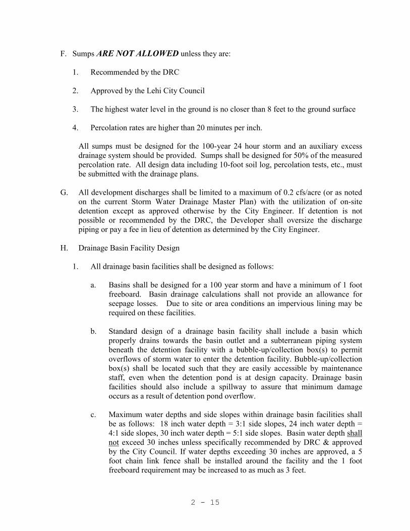
F. Sumps ARE NOT ALLOWED unless they are:
1. Recommended by the DRC 2. Approved by the Lehi City Council 3. The highest water level in the ground is no closer than 8 feet to the ground surface 4. Percolation rates are higher than 20 minutes per inch.
All sumps must be designed for the 100-year 24 hour storm and an auxiliary excess
drainage system should be provided. Sumps shall be designed for 50% of the measured percolation rate. All design data including 10-foot soil log, percolation tests, etc., must be submitted with the drainage plans.
G. All development discharges shall be limited to a maximum of 0.2 cfs/acre (or as noted
on the current Storm Water Drainage Master Plan) with the utilization of on-site detention except as approved otherwise by the City Engineer. If detention is not possible or recommended by the DRC, the Developer shall oversize the discharge piping or pay a fee in lieu of detention as determined by the City Engineer.
H. Drainage Basin Facility Design
1. All drainage basin facilities shall be designed as follows:
a. Basins shall be designed for a 100 year storm and have a minimum of 1 foot freeboard. Basin drainage calculations shall not provide an allowance for seepage losses. Due to site or area conditions an impervious lining may be required on these facilities.
b. Standard design of a drainage basin facility shall include a basin which
properly drains towards the basin outlet and a subterranean piping system beneath the detention facility with a bubble-up/collection box(s) to permit overflows of storm water to enter the detention facility. Bubble-up/collection box(s) shall be located such that they are easily accessible by maintenance staff, even when the detention pond is at design capacity. Drainage basin facilities should also include a spillway to assure that minimum damage occurs as a result of detention pond overflow.
c. Maximum water depths and side slopes within drainage basin facilities shall
be as follows: 18 inch water depth = 3:1 side slopes, 24 inch water depth = 4:1 side slopes, 30 inch water depth = 5:1 side slopes. Basin water depth shall not exceed 30 inches unless specifically recommended by DRC & approved by the City Council. If water depths exceeding 30 inches are approved, a 5 foot chain link fence shall be installed around the facility and the 1 foot freeboard requirement may be increased to as much as 3 feet.

2 - 16
d. Each drainage basin shall be covered with a combination of grass and xeriscape with a sprinkler system, unless otherwise approved. A minimum of 20% of the total basin area shall be xeriscaped. No trees shall be planted along the banks of a drainage basin.
e. Drainage basin berms should have a minimum width of 3 feet for small basins
and up to 12 feet for large basins as approved by the City Engineer. Side slopes along the outside of drainage berms shall be a minimum of 3:1, unless otherwise approved by the City Engineer.
f. Detention basins within parking lots shall be limited to a water depth of 18
inches, unless otherwise approved. Detention basins within parking lots shall overflow to a city street, storm drain, or other approved outfall.
2. Detention discharges may be limited through the use of orifice plating or small
discharge pipes. Orifice plates should be installed within public right-of-way. Orifice plate discharges should be designed to reduce clogging and allow for easy maintenance during storm events. Small discharge pipes may also be used in lieu of orifice plates (if approved by the City Engineer), provided that pipe lengths are kept to below 40 feet. A BMP “snout” may be required by City staff to meet storm water quality requirements, but orifice plates shall not be designed beneath “snout” hoods unless otherwise authorized by the City Engineer.
3. For single lots or small areas, the above may be waived so that drainage can be
directed on to private property with a drainage easement (with written approval of the property owner).
4. Underground detention systems shall be registered with the Utah DEQ Underground
Injection Control Program. It is the responsibility of the owner to comply with all Utah DEQ requirements for underground detention.
I. Allowable use of streets for initial storm runoff in terms of pavement encroachment is as
follows: Street Classification Maximum Encroachment Local No curb over-topping. Flow may spread to
crown of street. Collector No curb over-topping. Flow spread must
leave at least one lane in each direction free of water.
Arterial No curb over-topping. Flow spread must
leave at least one lane in each direction free of water.

2 - 17
J. Inlet grating maximum design capacity for a standard bicycle safe 1 foot x 4 foot grate is 3.0 cfs.
K. All drainage piping for surface (12 inch minimum size) and subsurface drainage (8 inch minimum size) shall have manholes at a maximum spacing of 400 feet, unless otherwise approved by the City Engineer. Minimum slopes shall be the same as required by the Utah State Division of Health for sanitary sewers (roughness coefficient consistent with their criteria is n= 0.013).
L. Devices such as snouts/oil & water separators, etc., may be required by the City to reduce
downstream contamination, especially on business applications.
SECTION 2.13 BEST MANAGEMENT PRACTICES
These standards apply to all land development and construction activities as defined within the Lehi Development Code. The purpose of these standards is to minimize the introduction of pollutants into the storm drainage system, provide a means to monitor and control discharges into the storm drain system, and to comply with the State and Federal laws and regulations regarding these discharges. The Public Works Director or City Engineer has the authority to modify the requirements of the Best Management Practices (BMPs) as needed to accomplish reasonable and effective storm water pollution prevention objectives.
A. Requirements for proposed developments one (1) acre or larger are as follows:
1. Incorporate Best Management Practices (BMPs) into development design to limit quantity of runoff and preserve quality of runoff.
2. Prepare Storm Water Pollution Prevention Plan.
3. Provide financial guarantee that improvements contained in the Storm Water
Pollution Prevention Plan will be installed and maintained.
4. Provide instruction to construction site operators regarding implementation of the Storm Water Pollution Prevention Plan. 5. Monitor effectiveness of the elements included in the Storm Water Pollution
Prevention Plan, and make improvements as necessary to achieve the plan objectives.
6. Provide verification that improvements were constructed as approved. 7. Prepare Post Construction Storm Water Pollution Prevention Plan. 8. Obtain UPDES Permit.

2 - 18
B. Requirements for construction activities associated with existing developments are as
follows:
1. Submit and obtain approval of a Post Construction Storm Water Pollution Prevention Plan.
2. Operator or owner shall make adjustments to practices or improvements when
necessary to achieve Post Construction Storm Water Pollution Prevention Plan objectives.
SECTION 2.14 SIGNS
A. Stop signs shall be posted at all exits of subdivision roads to city streets where warranted under the MUTCD and/or required by the City for adequate traffic control. Slow, railroad, etc., signs may be required as applicable. Street signs shall be posted at all intersections. Design and installation shall comply with the standards as set forth in the latest edition of the Manual on Uniform Traffic Control Devices (MUTCD) published by the U.S. Dept. of Transportation. Materials shall comply with Utah State Highway Department requirements. In no case shall any traffic control device be installed which does not meet applicable engineering warrants or which does not meet applicable minimum standards.
SECTION 2.15 LOT CORNERS
A. All lot corners shall be marked with an approved type of metal peg at least 5/8 inches in diameter and twenty-four inches in length. All lot corners adjacent to street frontage shall be projected to curb and gutter and indicated by a copper rivet. Corner markers must be installed prior to issuance of any building permits.
SECTION 2.16 DEDICATIONS
A. All streets within and adjacent to a proposed development must be dedicated in conformance with Lehi Road Master Plan except as otherwise allowed within the Lehi City Development Code and approved by the City Engineer and City Council.
B. Where natural or scenic features and/or historic community assets exist, such locations
are to be safeguarded either by dedication to a public or private agency by the subdivider.
C. Property for natural channels such as Dry Creek and manmade irrigation channels such as the Waste Ditch, shall be dedicated to Lehi City from top of bank to top of bank of the existing channel. Dedication for additional property may be requested by the DRC to allow for maintenance and access to the channel.

2 - 19
SECTION 2.17 TRAILS These standards apply to all trail corridors required by the Lehi City General Plan. Trails shall be constructed within all proposed projects where they are indicated on the General Plan Land Use Map, and shall be installed by the developer as part of the required public improvements for the development unless otherwise recommended by the Planning Commission and approved by the City Council. In addition to these minimum standards, the City Engineer will be guided by and may impose any necessary additional standards contained in the current AASHTO Guide for the development of Bicycle Facilities or the Utah Valley Non-Motorized Transportation System Manual.
A. Required trails shall be grade separated, paved, multiple-use pathways (except the
Bonneville Shoreline Trail, which is not paved), and users shall be non-motorized and may include but are not limited to: bicyclists, roller skaters, wheelchair users, pedestrians, and in some areas equestrian riders.
B. Paved trails are to be constructed of bituminous pavement no less than two and one half
(2 1/2) inches thick and a base course of no less than six (6) inches thick or concrete no less than four (4) inches thick.
C. Minimum trail width shall be ten (10) feet, with a two (2) foot shoulder/clear zone on
each side unless otherwise approved by the City Engineer due to physical constraints within the designated trail area. Sharp grade transitions, trees, signs and other fixed objects within the shoulder/clear zone shall not be permitted.
D. If the trail is designated for equestrian use in addition to other users, an additional six (6)
foot equestrian area shall be provided using existing stabilized dirt, gravel or other approved surface and an appropriate sub-surface that will allow for drainage as necessary.
E. A minimum vertical clearance of ten (10) feet shall be maintained from the equestrian trail surface.
F. Trails shall be located within a permanent right of way (or as approved otherwise by the
City Engineer) that allows for the construction, operation, maintenance, repair and/or replacement of the pathway. Minimum width shall be twenty (20) feet unless otherwise approved by the City Engineer due to physical or other constraints within the designated trail area.
G. Trails are to be located with a minimum offset from any road surface of twelve (12) feet.
Lesser distances may be allowed when approaching intersections of streets to provide a safe alignment for crossing at the intersection or where the trail must be routed along a roadway.
H. Trails will generally follow the longitudinal slope of the existing ground, with
adjustments in grade provided for intersecting streets or drives.
2 - 20
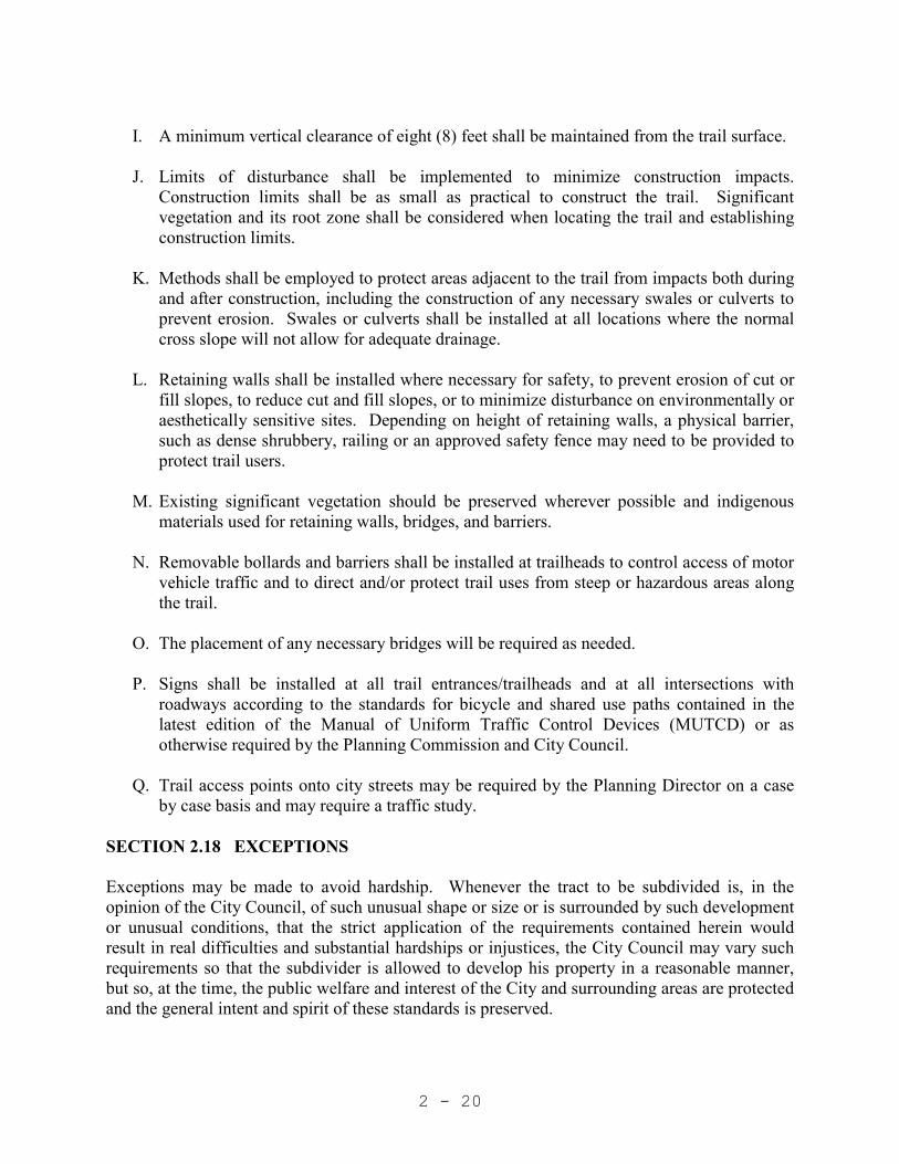
I. A minimum vertical clearance of eight (8) feet shall be maintained from the trail surface.
J. Limits of disturbance shall be implemented to minimize construction impacts.
Construction limits shall be as small as practical to construct the trail. Significant vegetation and its root zone shall be considered when locating the trail and establishing construction limits.
K. Methods shall be employed to protect areas adjacent to the trail from impacts both during
and after construction, including the construction of any necessary swales or culverts to prevent erosion. Swales or culverts shall be installed at all locations where the normal cross slope will not allow for adequate drainage.
L. Retaining walls shall be installed where necessary for safety, to prevent erosion of cut or
fill slopes, to reduce cut and fill slopes, or to minimize disturbance on environmentally or aesthetically sensitive sites. Depending on height of retaining walls, a physical barrier, such as dense shrubbery, railing or an approved safety fence may need to be provided to protect trail users.
M. Existing significant vegetation should be preserved wherever possible and indigenous
materials used for retaining walls, bridges, and barriers.
N. Removable bollards and barriers shall be installed at trailheads to control access of motor vehicle traffic and to direct and/or protect trail uses from steep or hazardous areas along the trail.
O. The placement of any necessary bridges will be required as needed.
P. Signs shall be installed at all trail entrances/trailheads and at all intersections with
roadways according to the standards for bicycle and shared use paths contained in the latest edition of the Manual of Uniform Traffic Control Devices (MUTCD) or as otherwise required by the Planning Commission and City Council.
Q. Trail access points onto city streets may be required by the Planning Director on a case by case basis and may require a traffic study.
SECTION 2.18 EXCEPTIONS Exceptions may be made to avoid hardship. Whenever the tract to be subdivided is, in the opinion of the City Council, of such unusual shape or size or is surrounded by such development or unusual conditions, that the strict application of the requirements contained herein would result in real difficulties and substantial hardships or injustices, the City Council may vary such requirements so that the subdivider is allowed to develop his property in a reasonable manner, but so, at the time, the public welfare and interest of the City and surrounding areas are protected and the general intent and spirit of these standards is preserved.

2 - 21
SECTION 2.19 SHARING COST OF IMPROVEMENTS
A. Cost of improvements, which are required under the provisions of these regulations, as well as the cost of other improvements, which the developer may install, shall be shared between the developer and the City, according to the following schedule:
Facility Developer City 1. Road right-of-way "on-site" and "off-site"
100% up to 56 feet in width (unless Development's specific traffic requirements mandate additional.)
Balance of right of way (raw value price, prior to development).
2. Grading and drainage of streets and "on-site"
100% 0%
3. Grading and drainage of streets "off-site"
100% 0%
4. Bridges and Culverts 100% for all local and
collector streets Special negotiations with City
on work performed on arterial streets.
5. Street paving
100% for all streets up to 34 feet of pavement width (unless the Development’s specific traffic requirements mandate additional.)
Balance of pavement installed.
6. Curb and gutter 100% 0%
7. Sidewalk 100% 0% 8. Street Signs 100% 0% 9. Traffic Signs 100% 0%

2 - 22
10. Culinary & Pressure Irrigation Water Systems
100% 0%*
11. Sewer System 100% 0%* 12. Street Lighting 100% 0% 13. Electrical Utilities 100% 0%* 14. Canal and Flood channel
100% 0%*
15. Parks/Trails As recommended by the City
Engineer and approved by the City Council
As recommended by the City Engineer and approved by the City Council
16. Survey Markers /Monuments
100% 0%
17. Water Rights 100% 0% 18. Grading lots and reseeding cut and fill slope
100% 0%
19. Soils, Concrete, etc. testing
100% 0%
20. Utility relocations 100% 0%
21. All other required improvements
100% 0%
* Should Lehi City determine that a larger size than that required for the proposed
Development is expedient for future growth, Lehi City may consider paying the increased costs associated with the extra sizing. The City's portion shall not exceed the multiplier listed below times the material cost increase for the oversizing unless otherwise approved by the City Engineer. This is intended to be a reimbursement to the developer. The Developer must provide the documentation including the supplier’s material cost differential (at the time of purchase).

2 - 23
Culinary & Pressurized Irrigation Pipe and Valve Over sizing Multipliers
Size Changes Material Cost Multiplier
2” 1.15
4” 1.20
6” 1.25
8” 1.30
10” 1.35
12” 1.40
14” 1.45
16” & up 1.50
(Plus an additional 7.5% for water lines to cover all fittings, etc., except valves.)
Sewer, Storm and Irrigation Drainage Pipe Over sizing Multipliers
Size Changes Material Cost Multiplier
2” 1.150
3” 1.175
4” 1.200
5” 1.225
6” 1.250
7” 1.275
8” 1.300
9” 1.325
10” 1.350
12” 1.400
15” 1.475
16” & up 1.500
Construction in Dry Areas Plus an additional 5.0% for sewer, storm and irrigation drainage
appurtenances and the removal and disposal of excess material. Construction in Wet Areas Plus an additional 15.0% for sewer, storm and irrigation drainage
appurtenances, removal and disposal of excess material, import of select backfill, dewatering and stabilization, etc. (as indicated within the soils report and/or through comparable installations in the area).
2 - 24
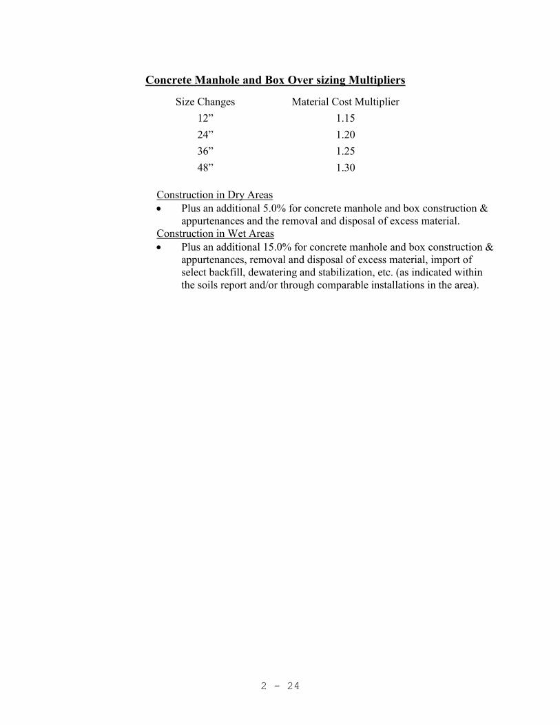
Concrete Manhole and Box Over sizing Multipliers
Size Changes Material Cost Multiplier
12” 1.15
24” 1.20
36” 1.25
48” 1.30
Construction in Dry Areas Plus an additional 5.0% for concrete manhole and box construction &
appurtenances and the removal and disposal of excess material. Construction in Wet Areas Plus an additional 15.0% for concrete manhole and box construction &
appurtenances, removal and disposal of excess material, import of select backfill, dewatering and stabilization, etc. (as indicated within the soils report and/or through comparable installations in the area).

3 - 1
CHAPTER 3 GENERAL CONSTRUCTION REQUIREMENTS SECTION 3.01 GENERAL
A. Prior to beginning construction on any improvements in a development or in the right-of-way of any streets or proposed streets of Lehi City, or with any work that will ultimately connect onto a City utility, the City Public Works Department shall be notified so that the proper inspection may be provided, and so that it might be determined that the work has been approved and the proper permits obtained. Certain types of construction shall have continuous inspection while others may have only periodic inspections.
1. Continuous inspection by project inspector shall be required on the following
types of work and materials: a. Street grading and gravel base. b. Excavations for curb and gutter and sidewalks. c. Laying of street surfacing. d. Placing of concrete for curb and gutter, drive approaches, sidewalks and
other structures. e. Laying and testing of culinary and pressurized irrigation water pipe, valves,
hydrants, drainage pipe, sewer pipe, and appurtenances. f. All materials installed within the city’s culinary, pressurized irrigation, and
sewer systems will be inspected and approved by the project inspector.
2. Periodic inspections shall be required on the following: a. Excavations for structures. b. Trenches for laying pipe. c. Forms for curb and gutter, sidewalks and structures.
B. On construction requiring continuous inspection, no work shall be started except in the
presence of a City Inspector. No construction requiring inspection shall be performed on City Holidays, Saturday, Sunday or non-business hours (which generally includes Friday except as specifically agreed-upon with the applicable Lehi City Inspector). A minimum of 48 hours’ notice shall be given to the applicable inspector before any construction may proceed. The owner may be charged a fee for any additional inspections.
C. It shall be unlawful to do any construction, excavation work on any street, curb, gutter,
sidewalk, drive approach, sewer line, water line or other infrastructure addition or improvement in Lehi City without an approved set of drawings that has been stamped by the City as the official construction set, the plat is recorded, bonding is in place, and then a preconstruction meeting is held. (This set of plans will be valid for a period of one year only)

3 - 2
SECTION 3.02 REQUESTS FOR INSPECTION
A. Requests for inspections shall be made to the City Inspector by the person responsible for the construction. Requests for inspection on work requiring continuous inspection shall be made three (3) working days prior to the commencing of the work. Notice shall also be given one working day in advance of the starting of work requiring periodic inspection.
B. Prior to construction the following data (5 complete copies) shall be furnished to the
Inspector: "Cut Sheets" for sewer, curb and gutter work, samples of road base material to be used, projected time schedules for completion of the work and shop drawings for materials, etc., to be installed.
C. No work which may be defective in its construction or deficient in any of the
requirements of these Specifications will be accepted. Failure of any officers of the City or the Inspector to point out such defects or deficiencies during construction shall not relieve the Contractor of his responsibility to comply with the specifications, and the Contractor shall correct any imperfect work, settlement, etc., wherever discovered, before the final acceptance of the work by the City.
SECTION 3.03 EROSION AND SEDIMENTATION CONTROL PLAN
A. An erosion and sedimentation control plan must be submitted to the Public Works Director for approval before or during the project preconstruction meeting.
SECTION 3.04 AS –BUILT REQUIREMENTS
A. As-built data is collected by Lehi City. A payment is made to the City with the construction bond for the as-built data.
B. The contractor and/or developer shall not backfill any public utility until GPS data has
been collected by the Lehi City GIS Coordinator. The developer and/or contractor shall contact the Lehi City GIS Coordinator Prior to backfilling any public utility to allow for GPS data collection.
C. Detention Basin Acceptance. Prior to acceptance of detention basin construction, a Registered Professional Engineer shall provide a stamped letter and exhibit verifying that the constructed volume, side slopes, high water/spillway elevations, box/orifice plate elevations, pipe sizes and slopes, etc. have met the requirements set forth within the storm drainage report and the construction plans.
SECTION 3.05 CONSTRUCTION COMPLETION INSPECTION
A. An inspection shall be made by the Lehi City Public Works Department after all construction work is completed. Any faulty or defective work shall be corrected by the persons responsible for the work within a period of thirty (30) days of the date of Public

3 - 3
Works Department Inspection Report defining the faulty or defective work. Three complete sets of As-built (record) drawings shall be provided to the City.
SECTION 3.06 GUARANTEE OF WORK
A. The improvements outlined in this document shall be guaranteed through Escrow bonds and/or Letters of Credit.
SECTION 3.07 BUILDING PERMITS
A. For residential projects with either single-family detached or single-family attached units (townhomes, etc.), the untreated gravel base must be placed and graded, and the sewer, drains and drain facilities, water lines and power lines must be completed and tested before any building permits will be issued.
B. For non-residential /commercial projects or large multi-family residential attached
projects including apartment and condominium projects, building permits may be issued in advance of the road and utility improvements being completed if the project is adjacent to an existing road(s), and all necessary utility infrastructure is immediately available to the project, unless otherwise determined by the Development Review Committee due to public safety or other special circumstances where this infrastructure would be required to be installed prior to the building permit being issued.
C. For non-residential/commercial projects or large multi-family residential attached
projects including apartment and condominium projects where all necessary utility infrastructure is not immediately available, the Development Review Committee shall review each project on a case by case basis to determine the amount of infrastructure that will be required prior to issuance of a building permit.
D. The City Council may allow exceptions to these requirements for non-
residential/commercial developments or large multi-family residential attached projects including apartment and condominium projects. All requests for exceptions shall be reviewed by the DRC and their recommendations provided to the City Council prior to approval of an exception. It is the responsibility of each applicant to provide sufficient information to demonstrate the reason and justification for the exception, and that they can provide acceptable temporary alternatives for power, water and fire protection during construction.
SECTION 3.08 CONSTRUCTION TRAFFIC CONTROL
A. Maintain proper and sufficient barricades, signals, or warnings as needed at every construction site to give warning of and protect against accidents. Comply with requirements of the Manual Uniform Traffic Control Devices (MUTCD) for all traffic control on public streets. The Contractor shall provide the Public Works Department with a traffic control plan including a map of the work zone. No city street shall be

3 - 4
closed without the authorization of the Public Works Department. SECTION 3.09 FIRE DEPARTMENT ACCESS
A. Approved vehicle access for firefighting shall be provided to all construction or demolition sites. Vehicle access shall be provided to within 100 feet of temporary or permanent fire department connections. Vehicle access shall be provided by either a twenty (20) foot minimum width temporary or permanent road, capable of supporting vehicle loading under all weather conditions. Vehicle access shall be kept clear of all fencing, barricades, dumpsters, vehicles, construction materials and debris and maintained until permanent fire apparatus access roads are available.
SECTION 3.10 MATERIALS TESTING
A. All costs associated with testing (compaction, concrete, etc.), from an independent testing agency (approved by the Lehi City Public Works Department), as required herein shall be the responsibility of the Developer/Contractor.

4 - 1
CHAPTER 4 EARTHWORK SECTION 4.01 GENERAL This Section defines the requirements for excavation and backfill for structures, construction requirements for embankments and fills, and subgrade preparation for pavements and other surface improvements. SECTION 4.02 EXCAVATION PERMIT REQUIREMENTS Prior to the excavation or encroachment within any City street, an Encroachment Permit with required fee must be obtained from the Lehi City Public Works Department. The applicant must show proof that a competent licensed contractor will do the work, present evidence of sufficient public liability insurance, post the required cash bond (returned upon satisfactory completion of project), and provide a proctor for the backfill material. Failure to contact the Public Works Department prior to commencement of work will result in the requirement to remove all asphalt and/or backfill at the contractor/developer’s expense. Also, surrendering of all fees submitted for the Encroachment Permit may be requested. SECTION 4.03 EXCAVATION FOR STRUCTURES
A. All structures shall be founded on undisturbed original subsoil. All authorized excavation below the specified structure subgrade shall be replaced with concrete, monolithic with that of the slab above or with coarse gravel thoroughly compacted into place.
B. Subgrade soil for all concrete structures, regardless of type or location, shall be firm,
dense, thoroughly compacted and consolidated; shall be free from mud and muck; and shall be sufficiently stable to remain firm and intact under the feet of the workmen engaged in subgrade surfacing, laying reinforcing steel, and depositing concrete. Coarse gravel or crushed stone may be used for subsoil reinforcement if results satisfactory to the City Engineer or City Inspector can be obtained thereby. Such material shall be applied in layers, not exceeding 6 inches in thickness, each layer being embedded in the subsoil by thorough tamping. All excess soil shall be removed to compensate for the displacement of the gravel or crushed stone and the finished elevation of any subsoil reinforced in this manner shall not be above the specified sub-grade.
SECTION 4.04 BACKFILL AROUND STRUCTURES
A. Backfill around structures shall be placed to the lines shown in the approved Drawings. After completion of foundation footings and walls and other construction below the elevation of the final grades, and prior to backfilling, all forms shall be removed and the excavation shall be cleaned of all trash and debris. Material for backfilling shall consist

4 - 2
of excavated material or borrow of sand, gravel, or other suitable material, and shall be placed in layers not exceeding eight (8) inches in uncompacted thickness. Each layer shall be compacted by hand or by other suitable equipment to a density equal to 95% of maximum dry density as measured by AASHTO T-99. Backfill around curb and gutter in fill sections shall extend 18 inches beyond outside of the concrete gutter.
SECTION 4.05 CONSTRUCTION OF EMBANKMENTS AND FILLS
A. Unsuitable materials that occur in the foundations for embankments and fills shall be removed by clearing, stripping, and/or grubbing. Where suitable materials occur, after stripping, the foundation shall be scarified to a depth of not less than 6 inches, and the loosened material shall be moistened and compacted as hereinafter specified for each layer. All materials in embankments and fills shall be placed, moistened, and compacted as provided in the following paragraphs.
B. When the embankment or fill exceeds the amount of excavation, sufficient additional
material shall be obtained from borrow pits provided by the Contractor. All material proposed to be imported shall be subject to the review and approval of the City Engineer or City Inspector prior to starting of hauling operations.
C. The materials used for embankment and fill construction shall be free from sod, grass,
trash, frozen earth, rocks larger than 6 inches in diameter, and all other material unsuitable for construction of compacted fills.
D. Grading of completed embankments and fills shall bring the surfaces to a smooth,
uniform condition with final grades being within 0.1 feet of the design grade. SECTION 4.06 COMPACTING EARTH MATERIALS
A. The material shall be deposited in horizontal layers having a thickness of not more than 6 inches after being compacted as hereinafter specified, provided that when mechanical equipment is used for placing and compacting the material on a sloping foundation, the layers may be placed parallel to the foundations. The distribution of materials shall be such that the compacted material will be homogeneous and free from lenses, packets, or other imperfections.
B. Prior to and during compaction operations the material shall have the optimum
moisture content required for the purpose of compaction and the moisture content shall be uniform throughout the layers, insofar as practicable. Moistening of the material shall be performed at the site of excavation, but such moistening shall be supplemented, as required by sprinkling at the site of construction. If the moisture content is less than optimum for compaction, the compaction operations shall be delayed until such time as the material has dried to the optimum moisture content. When the material has been conditioned as hereinbefore specified, the backfill or embankment shall be compacted as follows:

4 - 3
1. Under Roadways and extending one foot beyond the proposed top back of curb the fill or embankment material shall be compacted to a density equal to not less than 95% of maximum dry density as measured by AASHTO T-99.
2. Under the Sidewalks, Driveways and other Structures the fill or embankment
material (to at least one foot each side of the edge of the slab) shall be compacted to a density equal to not less than 95% of maximum dry density as measured by AASHTO T-99.
3. Other Fills and Embankments not listed above shall be compacted to a density
equal to not less than 90% of maximum dry density as measured by AASHTO T-99.
SECTION 4.07 SLOPES
A. The slopes of excavations and/or fills shall be shaped to meet safety requirements dependent on soil types, but in no case shall the finished slope be in excess of 2:1 for cut areas or 2:1 for fill areas except as approved otherwise by all governing agencies.

5 - 1
CHAPTER 5 PORTLAND CEMENT CONCRETE SECTION 5.01 GENERAL This Section of the Specifications defines materials to be used in all Portland Cement concrete work and requirements for mixing, placing, finishing, and curing. SECTION 5.02 MATERIALS Materials used in Portland Cement concrete and reinforcing of Portland Cement concrete shall meet the following requirements:
A. Cement: Portland Cement shall be low alkali Type II or Type III and shall comply with the Standard Specification for Portland Cement, ASTM C-150.
B. Aggregates: Concrete aggregates shall comply with ASTM C-33 latest edition.
Maximum aggregate size shall be 1 inch.
C. Water: Water used in mixing concrete shall be clean and free from oil, acid, salt, injurious amounts of alkali, organic matter, or other deleterious substances.
D. Entraining Agent: An air-entraining agent shall be used in all concrete exposed to the
weather. The agent shall conform to ASTM Designations C-175 and C-260.
E. Admixtures: No admixture will be permitted to be used in Portland Cement concrete unless such use is specifically authorized by the City Engineer.
F. Reinforcing Steel: All bar material used for reinforcement of concrete shall be
intermediate grade steel conforming to the requirements of ASTM Designation A-615 and shall be deformed in accordance with ASTM Designation A-305. The reinforcing shall be clean and free from rust, scale, paint, grease or other foreign matter which might impair the bond.
G. Welded Wire Fabric: Welded wire fabric for concrete reinforcement shall conform to the
requirements of ASTM A-185.

5 - 2
SECTION 5.03 CONCRETE MIX
A. For the purpose of practical identification, concrete has been divided into four classes, Class A, B, C and D as follows:
Class
Minimum Cement (94 lb. sacks/c.y.)
Recommended 7-day Comp. Strength
(psi)
Minimum 28-day Comp.
Strength (psi)
Primary Use A 6 ½ 3000 4000 Reinforced structural
concrete. B 6 ½ 3000 4000 Sidewalks, curbs and
gutter, cross gutter, pavements, and unreinforced footings and foundations.
C D
5
±1/2 (Submit Design)
1875
N/A
2500
50 - 150
Thrust blocks, anchors, mass concrete Flowable fill (5-10 inchslump)
B. All concrete shall also comply with the following requirements:
1. Aggregates: The maximum size of the aggregate shall be not larger than one-fifth of the narrowest dimension between forms within which the concrete is to be cast, nor larger than three-fourths of the minimum clear spacing between reinforcing bars or between reinforcing bars and forms. For unreinforced concrete slabs the maximum size of aggregates shall not be larger than one-fourth the slab thickness.
2. Water: Sufficient water shall be added to the mix to produce concrete with
minimum practicable slump.
a. Unless otherwise authorized by the City Engineer or City Inspector, the nominal slump for all concrete shall be 0-3 inches with a maximum slump of 4 inches. When adverse or difficult conditions affect the placement of the concrete, the City Engineer, or Inspector, may authorize a greater slump, provided both the water and cement are increased. Water shall be added at a ratio not to exceed 30 pounds per sack of added cement per cubic yard of concrete.
b. The consistency of the concrete shall be determined in accordance with
ASTM C-143.

5 - 3
c. The maximum permissible water-cement ratio (including free moisture on aggregates) shall be 5 and 5 3/4 gallons per bag of cement respectively for Class A and B air entrained concrete.
3. Air Entraining: Air content for air entrained concrete shall comply with the
following:
Course Aggregate Size (in)
Air Content (%)
3/4 or 1 6 ± 1 3/8 or 1/2 7 ± 1
The air entraining agent shall be added to the mixing water by means of
mechanical equipment capable of accurate measurement and control. SECTION 5.04 FORMS A. Forms shall be substantially built and adequately braced so as to withstand the liquid weight
of concrete. All linings, studding, walling, and bracing shall be such as to prevent bulging, spreading, or loss of true alignment while pouring and displacement of concrete while setting.
B. Metal forms shall be used for curb and gutter work except at curves. All edge forms for
sidewalk pavements, curbs, and gutters shall be of sufficient rigidity and adequately braced to accurately maintain line and grade.
C. Forms for curved sections shall be so constructed and placed that the finish surface of walls
and edge of sidewalks, curbs, and gutters will not deviate appreciably from the arc of the curve.
D. Exposed vertical and horizontal edges of the concrete in structures shall be chamfered by the
placing of moldings in the forms. SECTION 5.05 JOINTS
Joints shall be provided for sidewalk and curb and gutter as follows: A. Sidewalks shall have contraction joints at intervals equal to the width of sidewalk, but not
exceeding 2 times the slab thickness in feet. For example, the maximum joint spacing for a 4 inch thick concrete slab would be 8 feet. Contraction joints shall be approximately 3/16 inches wide and be a minimum of ¼ of the total slab thickness. Along curb, gutter, and sidewalk sections, ½ inch thick expansion joints (joint filler material) shall be placed the full depth of concrete plus 1 inch at every 50 foot increment, at major points of curvature, at each side of structures, and as otherwise noted within the standard details. In addition, 1/2 inch expansion joints should be provided at locations where sidewalks adjoin curbs or existing sidewalks.

5 - 4
B. Curb and Gutter shall have contraction joints placed at intervals not to exceed 10 feet.
Contraction joints should be placed with the use of 1/8 inch thick steel division plates of the exact cross section of the curb and gutter.
C. Concrete Removal/Replacement
a. Curb, gutter & sidewalk: When short (shorter than 8 feet long) sections of curb,
gutter or sidewalk must be removed & replaced, the entire section (from joint to joint) shall be removed. When surrounded by existing concrete sections, each concrete section to be removed shall be sawcut to the full depth of concrete once on one side of the section and twice on the opposite side (two sawcuts within 4-6 inches of each other) to ensure that the remaining concrete sections are not damaged during concrete removal. When replacing longer sections of curb, gutter, or sidewalk (longer than 8 feet long) the minimum section length replaced (or remaining) shall be 4 feet. ½ inch joint filler material shall be required at each side of concrete sections that are replaced.
b. 2. Sidewalk construction through drive approaches: In the event that sidewalks are
installed prior to the installation of drive approaches, and they are not constructed to meet the drive approach standards referenced within the Standard Details, all non-compliant sidewalk sections shall be removed and replaced as part of the drive approach construction.
D. Expansion Material - Material for 1/2 inch expansion joints shall be as defined in AASHTO
M-33, and shall be installed with its top approximately 1/4 inch below the concrete surface. SECTION 5.06 REINFORCING STEEL PLACEMENT A. Reinforcing bars shall be held accurately placed as shown on the approved plans and shall be
securely held in position in accordance with Concrete Reinforcing Steel Institute “Recommended Practice for Placing Reinforcing Bars,” and by using concrete or metal chairs, spacers, metal hangers, supporting wires, and other approved devices of sufficient strength to resist crushing under full load. No steel shall extend from or be visible on any finished surface.
B. Placing bars on layers of fresh concrete as the work progresses and adjusting bars during the
placing of concrete will not be permitted. No concrete shall be deposited until the placing of the reinforcing steel has been inspected and approved.
C. Splices of bars shall be made only where shown on the approved plans or as approved by the
City Engineer or City Inspector. Where bars are spliced, they shall be lapped at least 30 diameters. Splicing shall be accomplished by placing the bars in contact with each other and wiring them together.

5 - 5
D. Welding of reinforcing steel will not be permitted unless specifically authorized by the City Engineer or City Inspector.
SECTION 5.07 PREPARATIONS A. All utilities placed under areas to be paved shall be approved by the inspector prior to any
pavement being installed. Subbase may be placed over utilities to allow for deflection testing but no paving shall occur until the utilities have been approved by the inspector.
B. Before batching and placing concrete, all equipment for mixing and transporting the concrete
shall be cleaned, all debris and ice shall be removed from the places to be occupied by the concrete, forms shall be thoroughly wetted (except in freezing weather) or oiled, and masonry filler units that will be in contact with concrete shall be well drenched (except in freezing weather), and the reinforcement shall be thoroughly cleaned of ice or other coatings. Water shall be removed from spaces to receive concrete and kept below subgrade until the concrete has set.
C. When placing concrete on earth surfaces, the surfaces shall be free from frost, ice, mud, and
water. When the subgrade surface is dry soil or pervious material, it shall be sprayed with water immediately before placing of concrete or shall be covered with waterproof sheathing paper or a plastic membrane. No concrete shall be placed until the surfaces have been inspected and approved by the City Inspector or City Engineer.
SECTION 5.08 CONCRETE MIXING A. The concrete shall be mixed until there is a uniform distribution of the materials. Sufficient
water shall be used in mixing concrete to produce a mixture which will flatten and quake when deposited in place, but not enough to cause it to flow. Sufficient water shall be used in concrete in which reinforcement is to be imbedded, to produce a mixture which will flow sluggishly when worked and which, at the same time, can be conveyed from the mixer to the forms without separation of the coarse aggregate from the mortar. In no case shall the quantity of water used be sufficient to cause the collection of a surplus in the forms.
B. Ready-mixed concrete shall be mixed and delivered in accordance with the requirements set
forth in ASTM C-95. Concrete shall be delivered and deposited in its final position within 60 minutes after adding the cement and water to the mixture. Washing out of mixer trucks shall not be permitted within city rights-of-way.
SECTION 5.09 LAYOUT A. Curb and gutter shall be laid-out to be within 1-inch horizontally and ¼ -inch vertically from
true line at all locations. B. Sidewalk cross slope for new construction is 2-percent. Replacement sidewalk cross slope is
4-percent maximum, 1-percent minimum.
5 - 6
SECTION 5.10 DEPOSITING A. Concrete shall be deposited as nearly as practical in its final position to avoid segregation due
to re-handling or flowing. The concrete placing shall be carried on at such a rate that the concrete is at all times plastic and flows readily into the corners of forms and reinforcing bars. No concrete that has partially hardened or been contaminated by foreign material shall be deposited in the work, nor shall re-tempered concrete be used.
B. All concrete in structures shall be vibrator compacted during the operation of placing and
shall be thoroughly worked around reinforcement and embedded fixtures and into the corners of the forms.
C. After placement of concrete appurtenances, Contractor shall remove and discard all
remaining concrete and construction materials outside of the approved construction section.
SECTION 5.11 PLACING CONCRETE IN COLD WEATHER A. No concrete shall be poured where the air temperature is lower than 35 degrees Fahrenheit
unless adequate means are provided to heat the aggregates and water and protect the work. When concrete is poured below a temperature of 35 degrees Fahrenheit, the ingredients of the concrete shall be heated so that the temperature of the mixture shall not be less than 50 degrees or more than 100 degrees Fahrenheit. Cement shall not be added while the temperature of the mixed aggregates and the water is greater than 100 degrees Fahrenheit. When there is likelihood of freezing during the curing period, the concrete shall be protected by means of an insulation covering to prevent freezing of the concrete for a period of not less than 7 days after placing.
B. Equipment for protecting concrete from freezing shall be available at the job site prior to
placing concrete. Particular care shall be exercised to protect edges and exposed corners from freezing. In the event heating is employed, care shall be taken to insure that no part of the concrete becomes dried out or is heated to temperatures above 90 degrees Fahrenheit. The housing, covering, or other protection used shall remain in place and intact at least 24 hours after the artificial heating is discontinued.
SECTION 5.12 FINISHING A. After the concrete for slabs has been brought to the established grade and screened, it shall be
worked with a magnesium float and then given a light broom finish. In no case shall dry cement or a mixture of dry cement and sand be sprinkled on the surface to absorb moisture or hasten hardening. Surface edges of all slabs shall be rounded to a radius of 1/2 inches.
B. After concrete has been poured in curb and gutter forms, it shall be puddled and spaded so as
to insure a thorough mixture, eliminate air pockets, and create uniform and smooth sides. Before the concrete has thoroughly set, and while the concrete is still green, the forms shall be removed and the front and top sides shall be finished with a float or steel trowel to make a uniform finished surface. Wherever corners are to be rounded, special steel trowels shall be

5 - 7
used while the concrete is workable and the corners constructed to the dimensions specified.
C. The top and face of the curb and also the top of the apron on combined curb and gutter must be finished true to line and grade, of uniform width, free from humps, sags, and without any irregularities or wavy surface appearances noticeable to the eye. The gutter shall not hold water to a depth of more than one eighth (1/8) of an inch, nor shall any portion of the top face (or surface) of the curb or gutter depart more than one eighth (1/8) of an inch (except at grade changes or curves) from a straight edge ten (10) feet in length, placed on the curb parallel to the center line of the street.
D. The cross section of curb, gutter and sidewalk placed shall match construction plan details.
Any deviation (rotation, cross-section, slope, etc.) from the approved construction details may require removal of said curb, gutter and sidewalk as determined by the City Engineer or City Inspector.
SECTION 5.13 CURING AND PROTECTION A. As soon as the concrete has hardened sufficiently to prevent damage all concrete placed as
part of curb, gutter, sidewalk, driveway approaches, collars, etc. shall be sealed with a curing compound or be sprinkled with water and kept wet for at least three (3) days. When a chemical curing agent is used, it must be applied in accordance with the manufacturer's specifications or as follows:
a. Keep surfaces moist until the curing compound is applied. b. Complete all surface finishing before applying compound. c. Warm chilled compound that is too viscous to a maximum of 90 degrees F. d. Apply curing compound immediately after finishing operations are completed, or as
otherwise recommended by curing compound manufacturer. e. Spray the entire surface of the concrete with a membrane curing compound at a
uniform rate of 100 ft2 /gallon, or as otherwise recommended by curing compound manufacturer.
f. Immediately re-spray any portion damaged before the ten-day curing expires.
B. The freshly finished surface shall be protected from hot sun and drying winds until it can be sealed or sprinkled as above specified. The concrete surface must not be damaged or pitted by rain. The contractor shall provide and use, when necessary, sufficient tarpaulins to completely cover all sections that have been placed within the preceding twelve (12) hours.
C. The Contractor shall erect and maintain suitable barriers to protect the finished surface. Any
section damaged from traffic or other causes occurring prior to its official acceptance shall be repaired or replaced by the contractor at his own expense in a manner satisfactory to the City Engineer or City Inspector.
5 - 8
SECTION 5.14 REMOVAL OF FORMS A. The periods of time for form removal set forth herein are permissive only and subject to the
Contractor assuming all risks that may be involved. The time periods are minimum with no allowance therein for external loads. At times of low temperature, or other adverse conditions, the City Engineer or City Inspector may require the forms to be kept in place for longer periods of time.
B. The time periods are predicated on the use of concrete to which no admixtures have been
added for the purpose of obtaining a high early strength, and upon the use of the same type of cement throughout the structure. If Type III Cement is used, the minimum time periods for stripping forms will be established by the City Engineer or City Inspector in accordance with the materials, methods to be used, and the stresses to which the structure may be subjected. Forms may generally be removed as follows:
a. Forms for concrete members subject to bending stresses, where the member relies
upon forms for vertical support, may be removed seven days after concrete is placed, providing concrete has developed sufficient strength.
b. Top slab forms other than that specified in (A) - 48 hours. c. Outside forms and inside wall forms which do not support the top slab forms - 16
hours. d. Forms for open channel walls - 16 hours. e. Arch sections in open cut - 12 hours.
SECTION 5.15 CONCRETE DELIVERY TICKETS A. The following information shall be furnished for each load of ready-mix concrete delivered
to the site: a. Number of cubic yards. b. The exact amount of cement (this can be indicated either by weight or quantity). c. The amount of sand (this can be indicated by weight or quantity). d. The amount of gravel (this can be indicated either by weight or quantity). e. The amount of mixing water, including moisture in aggregates (this can be indicated
either by weight or quantity). f. If water is added at job site, note amount. g. Amount of slump in inches. h. Type of cement. i. Amount of air entrainment (if any) when delivered at job site. j. Do aggregates meet ASTM specified - yes or no. Indicate maximum size of
aggregate. k. Amount and brand (or ASTM) of admixture other than air entraining agent (if any). l. Temperature of concrete. m. These tickets shall be given to the inspector; and if he or she is not on the job, the
superintendent or foreman shall obtain these tickets and see that they are delivered to the Public Works Department. The foreman shall note location of concrete on job.

5 - 9
B. If any of the concrete delivered to the job site does not meet these Specifications, as indicated on the delivery ticket, or tested by the City Inspector, the entire truck load may be rejected.
SECTION 5.16 CONCRETE TESTING A. The average strength of the concrete shall be verified based on the "strength test" in which
the average strength of three standard cylinders is determined. The owner/developer/City may elect to collect and test additional 7 day cylinder strength tests to allow for early utilization of the concrete surface or to provide an early warning of potential concrete mix design problems. However, the cylinder strength approved by the City shall be determined at 28 days. Twenty eight day cylinder strength test results shall be provided to City inspection staff within 5 working days of the 28th day. One strength test shall be made for the first 15 yards of concrete poured and for each additional 50 yards of concrete placed in any one day.
B. When submitted strength test results show a strength below that required, the concrete may
be subject to rejection. The contractor may elect to have made an alternate strength test on three core samples obtained in accordance with AASHTO designation T-24. The City Engineer or City Inspector will determine the location, in the particular pour in question, where the cores will be taken. They shall be tested as soon as practicable under his supervision. All costs for securing the testing will be paid by the contractor.
C. One (1) slump test and one (1) air test shall be made for the first 15 yards of concrete poured
and for each additional 50 yards of concrete placed in any one day.

6 - 1
CHAPTER 6 ASPHALT PAVING SECTION 6.01 GENERAL This Section covers the requirements for bituminous surface paving on roads. All streets shall be surfaced in accordance with the following:
A. 6-inch minimum or more (based on pavement design) crushed gravel base course over prepared subgrade.
B. 3-inch minimum or more (based on pavement design) compacted thickness plant mix asphalt surfacing.
C. 1-inch minimum or more (based on pavement design) compacted thickness plant mix asphalt overlay.
SECTION 6.02 ROAD SUB-GRADE PREPARATION
A. If the pavement design does not require any sub-base materials, the sub-grade shall be
scarified to a depth of 8 inches the full width of roadway section and the loosened material shall be moistened and compacted to the equivalent of 95% of the maximum dry density as measured by AASHTO T-99 (Standard).
B. If the pavement design or trench conditions require sub-base imported materials, the
sub-grade shall be over-excavated to the depth specified across the full width of roadway section and replaced with select granular material, (which as a minimum meets the A-1-a AASHTO classification as indicated in the following table) and be moistened and compacted as above.
Sieve size Percent passing No. 10 Sieve 50 max No. 40 Sieve 30 max No. 200 Sieve 15 max
C. No organic material, soft clay, spongy material, frozen earth, or other deleterious
material will be permitted in the scarified or imported subgrade layer. Rough subgrades shall be shaped and graded to within a tolerance of 0.15 feet of design grade and drainage shall be maintained at all times.
D. During the rolling operation, moisture content of the sub-grade layer shall be
maintained at not less than 97% or more than 105% of optimum moisture content. Rolling shall be continued until the entire road bed, (to one foot back of curb) is compacted to the specified density to a minimum depth of 8 inches.

6 - 2
SECTION 6.03 BASE COURSE
A. Base for all streets shall consist of select material, either natural or crushed, placed on a prepared sub-grade in reasonable close conformance with the lines, grades and dimensions shown on the plans.
B. Unless otherwise approved by the City Engineer, the road base material shall be
crushed rock or gravel and shall conform to the following gradation by weight: Sieve Size
Average Gradation
% Passing
Individual Sample Tolerances
1" 100% 100 -5 1/2" 85% 70-100 -5 #4 55% 41-68 +/-4 #16 31% 21-41 +/-3 #50 19% 10-27 +/-2 #200 9% 4-13 +/-2 C. Roadbase material shall be uniform in quality and well graded from course to fine. D. Before placing the road base the supplier or contractor furnishing the material shall
submit, if required by the City Engineer or City Inspector, sieve analysis of stock-piled material showing that it meets the above requirements.
E. Roadbase material shall be deposited and spread in uniform layer, without segregation
of size with such depth that when compacted the layer will have the required thickness. F. Each layer shall be compacted for the full width and depth by rolling with a pneumatic
roller weighing at least 10 tons. Alternate grading and rolling will be required to provide a smooth, even and uniformly compacted course true to cross section and grade. Places inaccessible to rolling shall be compacted with mechanically operated hand tampers.
G. The gravel base shall be compacted to not less than 95% maximum dry density as
determined by AASHTO T-1 80. Surfaces shall be true to the established grade with thickness being not less than 1/4 inch from the required layer thickness and with the surface elevation varying not more than 3/8 inch in ten-feet from the true profile and cross section.

6 - 3
SECTION 6.04 BITUMINOUS SURFACE COURSE
A. Over the compacted base course the Contractor shall place and compact a bituminous surface course. The surface course shall consist of a mixture of mineral aggregate and bituminous binder. Gradation of aggregate shall conform to one of the following gradations: 1. 3/4" Gradation: Sieve Size
Desirable Average Gradation
% Passing Gradation Band
Tolerances Individual Samples
3/4" 100 100 -5 3/8" 85 70-100 -5 No. 4 62 48-76 +/-4 No. 8 48 36-59 +/-4 No. 16 36 27-45 +/-3 No. 50 23 16-29 +/-2 No. 200 8 5-11 +/-2
2. 1/2" Gradation: Sieve Size
Desirable Average Gradation
% Passing Gradation Band
Tolerances Individual Samples
1/2" 100 100 -5 No. 4 81 61-100 -4 No. 8 59 43-75 +/-4 No. 16 44 32-55 +/-3 No. 50 26 19-33 +/-2 No. 200 10 7-12 +/-2 The aggregate shall be uniform quality and free from clay, vegetative matter and other deleterious substances.
B. The Contractor shall establish a mix gradation and the amount of bituminous material shall be subject to the approval of the City Engineer and shall meet the requirements of
6 - 4
the gradation selected. The asphalt content by weight shall be between 4.5 and 7 percent. Regardless of the bituminous content there shall not be more than 3% voids in the aggregate.
C. The bituminous material for surface course shall be AC 5, AC 10 or AC 15 asphalt
cement conforming to the requirements of ASTM D-445, 85-100 penetration at a temperature from 250 to 300 degrees F. Asphalt cement conforming to the requirements of ASTM M20-60 may be used when specifically approved by the City Engineer. The bituminous material shall be free of water and will contain no mineral matter other than that naturally contained in the asphalt.
D. The bituminous surface course shall be mixed at a mixing plant and spread and
compacted on the prepared base in conformance with the lines and dimensions shown on the plans and in accordance with these Specifications. All Structure edges (curbs, etc.) shall receive a "bituminous tack" coat.
SECTION 6.05 FULL DEPTH ASPHALT
A. Upon the approval of the City Engineer, the contractor may be allowed to install “full
depth” asphalt. Full depth asphalt is defined as a roadway section where the granular base course is replaced (substituted) with a thickness of bituminous course (asphalt) of equivalent strength. The contractor shall supply the City Engineer with pavement design calculations demonstrating that the substituted full depth section has equivalent strength to the standard composite section.
B. If the pavement design does not require any sub-base materials, the sub-grade shall be
scarified to a depth of 8 inches the full width of roadway section and the loosened material shall be moistened and compacted to the equivalent of 95% of the maximum dry density as measured by AASHTO T-99 (Standard).
SECTION 6.06 CONSTRUCTION METHODS AND EQUIPMENT
A. The methods employed in performing the work, all equipment, tools, and machinery and other appliances used in handling the materials and executing the work shall be the responsibility of the Contractor. The Contractor shall make such changes in the methods employed and in the equipment used as are necessary whenever the bituminous material being produced does not meet the specifications herein established.
SECTION 6.07 SPREADING AND COMPACTION
A. The bituminous mixtures shall be spread with self-propelled mechanical spreading and conditioning equipment capable of distributing at least a 12-foot width. Unless otherwise designated or directed by the City Engineer or City Inspector, bituminous base course more than 4 inches in total compacted thickness shall be spread in two or more courses, with no courses exceeding 4 inches in compacted thickness and no courses less than 1 inch in thickness. The mixture shall be spread and struck off in such

6 - 5
a manner that the finished surface shall result in a uniform smooth surface. The longitudinal joints in succeeding courses shall be off-set at least 6-inches transversely to avoid a vertical joint through more than one course.
B. The temperature of the bituminous mix shall be between 250 degrees F and 325 degrees
F when placing. C. After the mixture has been spread, the surface shall be rolled with a power driven roller,
weighing not less than 10 tons, in longitudinal direction commencing at the outside edge or lower side and proceeding to the higher side. Each pass of the roller shall overlap the preceding pass at least one-half the width of the roller. Rolling shall continue until 95% of the laboratory density as determined in accordance with ASTM Designation D-1559 for the bituminous mixture being used has been obtained.
D. Rolling operations shall be conducted in such a manner that shoving or distortion will
not develop beneath the roller. E. The surface of the pavement, after compaction, shall be uniform and true to the
established crown and grade. When tested with a ten (10) foot straight edge placed parallel to the centerline of the pavement, the surface of the pavement at any point shall not deviate from the lower edge of the straight edge by more than one eighth of an inch. All high and low spots shall be remedied immediately by removing the wearing course material over the affected areas and replacing it with fresh, hot wearing course and surface finish material and immediately compacting it to conform with the surrounding area.
F. The Contractor shall be responsible to keep all traffic off the completed surface for a
minimum period of 24 hours. SECTION 6.08 WEATHER LIMITATIONS
A. No bituminous surface shall be placed when the temperature of the air or road bed is below 50 degrees F, during rainy weather when the base is wet, or during other unfavorable weather conditions as determined by the City Engineer or City Inspector. The air temperature shall be measured in the shade.
SECTION 6.09 FLAGGING
A. Flagmen shall be required as directed to facilitate the safe control of traffic over highways and streets under construction at such locations as required and directed by the Public Works Director or the Streets Department Superintendent. Flagging shall be performed by adequately trained and equipped flagmen. All flagging shall be done as described in the Safety Orders covering flagmen of the Industrial Commission of Utah.

6 - 6
SECTION 6.10 TRENCH SETTLEMENT LIMITATIONS
A. All trench and associated street improvement areas must meet the minimum compaction requirements stated in Section 7. Should there be any problems meeting the compaction requirements stated therein due to saturated soil conditions and/or at the discretion of the City Engineer, the following may be required prior to concrete and asphalt work:
1. Trenches excavated and backfilled in the Fall shall set until June 1 at which time
the compaction shall be rechecked to determine the adequacy thereof. Contractor shall be responsible to maintain said trenches until final road surface is in place and accepted.
2. Trenches excavated and backfilled in the Spring or Summer shall set for 90 days
or more and then be rechecked.
3. Trenches may not be excavated in a public street right-of-way during the period from December 1 to March 1 unless approved otherwise by the City Engineer.
4. A proof roll of the excavated and backfilled material shall be provided. Proof roll
shall be completed with a fully loaded dump, concrete, water truck, etc. weighing a minimum of 20 tons. Any proof-rolled areas found to be yielding or cracking shall be removed, stabilized and proof-rolled again prior to acceptance.

7 - 1
CHAPTER 7 EXCAVATION AND BACKFILL FOR PIPELINES SECTION 7.01 GENERAL
A. Coordinate all interruptions of utility services with the Owner. Notify affected users
twelve hours in advance of, and restore service within four hours after, any interruption. City valves shall only be operated by city personnel or under their direction. Protect from damage any underground pipes, utilities or structures encountered. If such is damaged, restore to original condition.
SECTION 7.02 CONTROL OF GROUNDWATER
A. All trenches shall be kept free from water during excavation, fine grading, pipe laying, jointing, and embedment operations. Where the trench bottom is mucky or otherwise unstable because of the presence of groundwater, and in cases where the static groundwater elevation is above the bottom of any trench or bell holed excavation, such groundwater shall be lowered to the extent necessary to keep the trench free from water and the trench bottom stable when the work within the trench is in progress. Surface water shall be prevented from entering trenches.
B. All trench dewatering shall be done in accordance with Utah Department of
Environmental Quality (DEQ) requirements and the Utah Pollutant Discharge Elimination System (UPDES). Any conflicts and costs incurred by the improper disposal of this water shall be borne by the Contractor. No surface or subsurface water shall be allowed to enter the existing City sewer system.
SECTION 7.03 EXCAVATION FOR PIPELINE
A. All sewer and drain lines shall be constructed starting at the existing facilities and proceeding continuously up stream with no interim segments left unconstructed. No variance therefrom shall be allowed except upon written approval by the City Engineer.
B. Excavation for pipelines shall follow lines parallel to and equidistant from the location
of the pipe centerline. Provide neat cut on asphalt surfaces to be removed during trench work to prevent excessive asphalt damage. Sawcuts or excavations adjacent to or within three feet of other existing patches, curb and gutter, or edge of asphalt shall include removal of existing pavement between excavation and existing patch. Trenches shall be excavated to the depths and widths required to accommodate the construction of the pipelines, as follows:
1. Except in ledge rock, cobble rock, stones or water-saturated earth, mechanical
excavation of trenches shall not extend below an elevation of 4 inches above the bottom of the pipe after placement in its final position. All additional excavation necessary for preparation of the trench bottom shall be made manually. Any

7 - 2
unauthorized excavation made below grade for any reason shall be backfilled as specified under "Foundation Stabilization."
2. Excavation for trenches in ledge rock, cobble rock, stones, mud or other material
unsatisfactory for pipe foundation, shall extend to a depth of at least 4 inches below the bottom of the pipe. A bedding of special material shall be placed and thoroughly compacted with pneumatic tampers in 4 inch lifts to provide a smooth, stable foundation. Special bedding material shall consist of suitable earth materials free from roots, sod, or vegetative matter. Trench bottoms shall be hand shaped.
3. Where unstable earth or mud is encountered in the excavation at the grade of the
pipe, a stable foundation must be created by removing the unsuitable material and backfilling with foundation stabilization material (depth 6 inches to 24 inches as required).
4. The unsuitable wet material or muck shall be hauled off and disposed of by the
Contractor. The Contractor shall take whatever measures are necessary to prevent the dry and wet trench materials from being commingled.
5. The maximum width of trench, measured at the top of the pipe, shall be as narrow
as possible but, not wider than 12 inches on each side of the pipe. SECTION 7.04 FOUNDATION STABILIZATION
A. Wherever the subgrade material does not afford a sufficiently solid foundation to support the pipe and super-imposed load, where water must be drained to maintain a dry bottom for pipe installation and at other locations as previously defined, the subgrade shall be excavated to the specified depth and replaced with crushed rock or gravel.
B. Gravel for pipe foundations shall be clean crushed rock or gravel conforming to the
following gradation: Screen % Passing 1 ½" 100 3/4" 5
C. Gravel material shall be deposited over the entire trench width in 6 inch maximum layers; each layer shall be compacted by tamping, rolling, vibrating, spading, slicing, rodding or by combination of one or more of these methods. In addition the material shall be graded to produce a uniform and continuous support for the installed pipe.

7 - 3
SECTION 7.05 BLASTING
A. Blasting may be allowed by permission from the Fire Department and by filling out an application and obtaining a permit as per the International Fire Code from the Lehi Fire Department. The Contractor shall comply with all laws, ordinances, and applicable safety code requirements and regulations relative to the handling, storage, and use of explosives and protection of life and property. The Contractor shall be fully responsible for all damage attributable to blasting operations. Excessive blasting or over-shooting will not be permitted and any material outside the authorized cross-section which may be shattered or loosened by blasting shall be removed by the Contractor.
SECTION 7.06 SHEETING, BRACING AND SHORING OF EXCAVATIONS
A. Excavation shall be sheeted, braced, and shored as required to support the walls of the excavations to eliminate sliding and settling and as may be required to protect the workmen, the work in progress, and existing utilities and improvements. All such sheeting, bracing, and shoring shall comply with the requirements of the Utah State Industrial Commission.
B. All damage resulting from lack of adequate sheeting, bracing, and shoring shall be the
responsibility of the Contractor, and the Contractor shall be responsible for all necessary repairs or reconstruction resulting from such damage.
SECTION 7.07 ACCESS TO TRENCHES
A. Safe and suitable ladders, which project 2 feet above the top of the trench, shall be provided for all trenches over 5 feet in depth. One ladder shall be provided for each 100 feet of open trench, or fraction thereof, and be so located that workmen in the trench need not move more than 50 feet to a ladder.
SECTION 7.08 BACKFILLING
A. The Contractor shall not proceed to backfill until each section of line has been inspected by the City. Backfill shall be carefully placed around and over pipes and shall not be permitted to fall directly on a pipe from such a height as to cause damage. In these Specifications, the process of preparing the trench bottom to receive the pipe to a level at the pipe center line is defined as bedding except for plastic in which case the bedding is considered to extend to 12 inches above the top of the pipe. Where the excavated material has rocks over ½ inch in diameter or the material is unstable making it unsuitable for bedding material, the zone shall be backfilled with approved pit-run gravel, crushed rock, sand, or other approved material (½ inch minus), or as recommended by the pipe manufacturer and accepted by the City Water and Waste Water Department. The contractor is to refer to R309-550(3)(a) and R309-550-8(3)(b) of the Administrative Rules for Public Drinking Water Systems for suitable materials to be used for pipe backfill around PVC and DIP pipe. 100% import material may be required by City
7 - 4
Inspector based upon existing field/moisture conditions. B. Bedding material shall first be placed so that the pipe is supported for the full length of
the barrel with full bearing on the bottom segment of the pipe equal to a minimum of 0.4 of the outside diameter of the barrel, then the remainder of the bedding shall be placed. Alternative methods of pipe laying which are recommended by the pipe manufacturer may be used if approved by the Engineer.
C. Sewer and storm drain piping shall be bedded in ¾” crushed, angular rock in dry conditions and up to 1 ½” crushed, angular rock in wet conditions as determined by the city inspector.
D. All water mains and services shall be bedded in a clean, sandy material to be approved by Lehi City inspectors.
E. Trench backfilling above the level of the pipe bedding shall normally be accomplished
with native excavated materials and shall be free from frozen earth, rocks and solid objects larger than 8 inches in diameter, except as required to protect pipe as per manufacturers’ specifications.
F. The backfill in all utility trenches shall be either compacted or consolidated according
to the requirements of the materials being placed, as follows:
1. The in-place density shall be a minimum of 95% of the maximum dry density as determined by ASTM D-698 (Standard) for all A-2 thru A-7 soils within the AASHTO classification system.
2. The in-place density shall be a minimum of 95% of the maximum dry density as determined by ASTM D-1557 (Modified) for A-1-a soils within the AASHTO classification system.
Perform a minimum of 1 test per 500 lineal feet of trench per 2 foot depth of trench to assure overall compliance. In the event that testing indicates additional compaction is required, perform additional testing as needed to assure compliance.
SECTION 7.09 BACK FILLING OF FIRE LINES
A. The trench shall be backfilled between joints before testing to prevent movement of the pipe.
B. Hydrostatic tests should be made before the joints are covered so that leaks can be readily detected. Thrust blocks should be sufficiently hardened before hydrostatic testing is begun. If the joints are covered with backfill prior to testing the contractor remains responsible for locating and correcting any leakage in excess of that permitted. (NFPA 24:10.10.2.6)
C. Where required for safety measures presented by the hazards of open trenches, the pipe

7 - 5
and joints shall be permitted to be backfilled, provided the installing contractor takes the responsibility for locating and correcting leakage. THIS REQUIRES FIRE DEPARTMENT APPROVAL (NFPA 24:10.10.2.7)
D. Backfill shall be tamped in layers or puddle under and around pipes to prevent settlement or lateral movement and shall contain no ashes, cinders, refuse, organic matter or corrosive materials. (NFPA 24:10.9.1)
E. Rocks shall not be placed in trenches. (NFPA 24:10.9.2) SECTION 7.10 CONSOLIDATION OF BACKFILL
A. Consolidation of backfill to within 4 feet of the ground surface, shall be mechanically compacted by means of tamping rollers, sheep foot rollers, pneumatic tire rollers, vibrating rollers, or other mechanical tampers.
B. Compaction by jetting will be permitted under the following conditions: (1) Backfill
consists of sand material which does not contain clay or other expansive material which prevents complete water penetration and material is totally free draining, and (2) the Contractor shall submit proposed procedures for review and approval to the City Engineer, at least 48 hours in advance of commencing work.
C. All precautions necessary shall be taken by the Contractor to prevent damage and
movement (including floating) of the pipeline, structures, and existing adjacent improvements and utilities. The allowance of the use of consolidation methods shall not be construed as guaranteeing or implying that the use of such methods will not result in damage to adjacent ground. The Contractor shall make his own determination in this regard and shall assume all risks and liability for settlement or lateral movement of adjacent ground, or improvements, or utilities, either on the surface of the ground or underground.
SECTION 7.11 COMPACTION OF BACKFILL (TOP 4 FEET OF TRENCH)
A. Backfill shall be compacted by means of sheepsfoot rollers, pneumatic tire rollers, vibrating rollers, or other mechanical tampers of a size and type approved by the City Engineer or City Inspector.
B. The backfill in all utility trenches shall be either compacted or consolidated according to the requirements of the materials being placed. Flowable fill may be used as approved by the City. Under pavements, or other surface improvements, and within 3 feet of finished grade the in-place density shall be a minimum of 95% of laboratory standard maximum dry density as determined by AASHTO T-99 (Modified). In shoulders the in-place density shall be a minimum of 90% of the maximum dry density as determined by the same laboratory method. Perform a minimum of 1 test per 500 lineal feet of trench per 2 foot depth of trench to assure overall compliance. In the event that testing indicates additional compaction is required, perform additional testing as needed to assure

7 - 6
compliance.
C. Where compaction methods are used, the material shall be placed at a moisture content such that after compaction, the required relative densities will be produced; also, the material shall be placed in lifts which, prior to the compaction, shall not exceed 12 inches. D. Prior to compaction each layer shall be evenly spread, moistened, and worked by disk
harrowing, or other means approved by the City Engineer or City Inspector.
E. If the required relative density is not attained, test sections will be required to determine any adjustments in compacting equipment, thickness of layers, moisture content, and compactive effort necessary to attain the specified minimum relative density.
F. Approval of equipment, thickness of layers, moisture content, and compactive effort shall not be deemed to relieve the Contractor of the responsibility for attaining the specified minimum relative densities. The Contractor in planning his work shall allow sufficient time to perform the work connected with test sections, and to permit tests for relative densities.
G. If, in the judgment of the City Engineer or City Inspector, the trench shows signs of being improperly backfilled, or if settlement occurs, the trenches will be reopened to a depth required for proper compaction, refilled, and recompacted, all in accordance with these specifications and to the satisfaction of the City Engineer or City Inspector.
SECTION 7.12 IMPORTED SELECT BACKFILL MATERIAL
A. In the event the native excavated material is not satisfactory for backfilling as determined by the City Engineer or City Inspector, the Contractor shall provide imported granular material. This granular material shall (as a minimum) conform to AASHTO designation A-1-a, and shall be free from sod, vegetation, and other organic or deleterious materials. The depth of material herein required may be up to 3 feet as determined by the City Engineer.
SECTION 7.13 RESTORATION OF SURFACE IMPROVEMENTS
A. Contractor shall restore all existing roadway surfaces in compliance with Section 11. SECTION 7.14 DISPOSAL OF EXCESS MATERIALS
A. All excess materials shall be hauled away from the construction site and disposed of by the Contractor.

7 - 7
SECTION 7.15 LOCATION OF STUB PIPES
A. The location of each water, pressure irrigation, sewer, and land drain stub shall be marked by placing a 2 x 4 marker at the end of the pipe and extending vertically from the end of the pipe to approximately 15 inches above the ground surface. Further, the portion of the 2 x 4 extending above ground shall be painted as follows:
Green …..indicating sewer stub Purple .....indicating irrigation stub Blue.........indicating culinary water stub White …..indicating land drain stub

8 - 1
CHAPTER 8 CULINARY AND IRRIGATION WATER LINES SECTION 8.01 GENERAL This section covers the requirements for piping materials and installation in the Lehi City Culinary and Secondary Irrigation/Fire Water Distribution Systems.
A. All materials and workmanship shall strictly comply with the Utah State Rules for Public Drinking Water Systems (USRPDWS) and the International Plumbing Code (IPC). In the event of conflict between this section, USRPDWS and the IPC, they shall rank in the following order of precedence: 1) this Code Section; 2) USRPDWS; 3) IPC. The end of water lines shall have a water tight plug when work is not in progress to prevent debris, animals, ground/surface water, etc., from entering the line. During construction no debris, animals, ground/surface water, etc., shall be allowed to enter the line.
B. Water lines shall be located on the north and east side of all roads unless approved by
the Water Superintendent as shown in the Standard Drawing Details. SECTION 8.02 CONCRETE THRUST BLOCKING
A. All fittings at bends and branches in water pipe lines shall be provided with concrete thrust blocking as shown on the Standard Drawings. Blocking shall be of 5-bag mix concrete, poured in place and shall bear against solid undisturbed earth at the sides and bottom of the trench excavation and shall be shaped so as to not obstruct access to the joints of the pipe or fitting. All fittings shall be covered with plastic or other approved materials prior to pouring the thrust block. FM Grade grease shall be used for all bolted fittings.
SECTION 8.03 PIPE LAYING
A. Install pipe with bell ends facing the direction of laying. Where pipe is laid on a grade
of 10 percent or greater, proceed uphill with the installation with the bell ends facing upgrade. Make gradual pipe elevation changes as practicable to clear existing obstructions.
B. The pipeline shall be installed so that a positive or negative grade is maintained
between high and low points to avoid air pockets. Provide air vents as required. If permanent air vents are not required, record location of all high points so they may be readily located. 2 inch and smaller solvent welded pipe shall have an expansion joint every 100 lineal feet or be "snaked" in the trench per manufacturers’ recommendations.

8 - 2
SECTION 8.04 DUCTILE IRON PIPE
A. GENERAL. All pipe 16 inches or larger shall be Ductile Iron unless otherwise approved by the City Engineer and Water Department Director. Pipes smaller than 16” may be required to be Ductile Iron Pipe due to pressures, terrain, site conditions, or distribution lines. Ductile Iron Pipe shall be Class 350 for slip-on or mechanical joint piping unless otherwise required by the City Engineer or Water Department Director.
B. MATERIALS. Ductile Iron Pipe for the transmission and distribution of water shall be
manufactured in accordance with AWWA C151 "American Standard for Ductile-Iron Pipe, Centrifugally Cast in Metal Molds or Sand-Lined Molds, for Water or Other Liquids". All pipe shall be made of good quality Ductile Iron and of such chemical composition and structure as is required to meet the physical and mechanical property requirements of the Standard. The metal for the Ductile Cast Iron Pipe shall be made by any suitable melting process.
C. JOINTS. Ductile Iron Pipe shall be of the following types, as indicated on the ap-
proved plans.
1. Mechanical joints and the rubber gaskets and lubricant therefore, for Ductile Iron Pipe, shall comply with the requirements and be dimensioned in accordance with AWWA C-151 and C-111. Bolts and rubber gaskets shall be furnished with mechanical joint pipe in sufficient quantity for the amount of pipe ordered. All mechanical joints shall include joint restraints such as Megalugs or other approved mechanical joint restraint.
2. Rubber gasket slip-on joints, and the rubber gaskets and lubricant therefore, for
Ductile Iron Pipe shall comply with the general requirements of AWWA C-111 of latest revision. a. Rubber gasket slip-on joints shall be designed for assembly by
prepositioning of a single continuous molded rubber ring gasket in an annular recess in the pipe socket, and forcing the plain end of the entering pipe into the receiving socket, thereby compressing the gasket radially to the pipe to form a positive seal. The plain end of the pipe shall be suitably beveled to facilitate assembly.
b. The design and shape of the gasket, and the annular recess therefore, shall
be such that the gasket is locked in place against displacement as the joint is assembled. The gasket shall provide adequate compressive force between the plain pipe end and the socket after assembly to affect a positive seal under all combinations of joint and gasket tolerances.
c. The recess in the pipe socket for the rubber ring shall be free of all coating
materials and sand pits. Rubber gaskets and lubricant shall be furnished with rubber gasket joint pipe in sufficient quantity to make each joint for the pipe ordered.

8 - 3
3. Cast Iron pipe flanges, and bolts and nuts therefore, shall be dimensioned in accordance with ASA B16.2 for Class 150. Threads for screwed on flange pipe shall comply with ASA B-2.1. Flange nuts and bolts shall be furnished with flange joint pipe in sufficient quantity to make each joint for the pipe ordered.
4. CONTRACTOR is to ensure and verify that all materials which may contact
drinking water comply with R309-550-6 of the Administrative Rules for Public Drinking Water Systems, which states:
“All materials which may contact drinking water, including pipes, gaskets, lubricants and O-Rings, shall be ANSI-certified as meeting the requirements of NSF Standard 61, Drinking Water System Components – Health Effects. To permit field verification, all such components shall be appropriately stamped with the NSF logo.”
D. LINING AND COATING.
1. The waterway surfaces of all Ductile-Iron Water Pipe and fittings shall be
completely covered with a uniform thickness of cement-mortar which shall be further covered with a bituminous seal coat, all in accordance with AWWA C-104. Ductile-Iron Pipe or fittings lined in the field will not be accepted as conforming to AWWA C-104.
2. The outside surface of all "buried" Ductile-Iron Pipe shall be coated with a
bituminous coating in accordance with AWWA C151 requirements. 3. Contractor is to ensure and verify that all materials which may contact drinking
water comply with R309-550-6 of the Administrative Rules for Public Drinking Water Systems, which states:
“All materials which may contact drinking water, including pipes, gaskets, lubricants and O-Rings, shall be ANSI-certified as meeting the requirements of NSF Standard 61, Drinking Water System Components – Health Effects. To permit field verification, all such components shall be appropriately stamped with the NSF logo.”
E. POLYETHYLENE ENCASEMENT. The outside surface of all Ductile-Iron Pipe shall
be encased with polyethylene film in tube or sheet form unless otherwise approved by the City Engineer.
1. The polyethylene film shall be manufactured of virgin polyethylene material
conforming to the requirements of ASTM Standard Specification D-1248-68 Polyethylene Plastics Molding and Extrusion Materials. The film shall have a minimum nominal thickness of 0.008 inches (8 mils) with a minus tolerance not exceeding 10 percent of the nominal thickness. The film shall be green for sewer, blue for culinary, and purple for pressurized irrigation.

8 - 4
2. The polyethylene encasement shall prevent contact between the pipe and the
surrounding backfill and bedding material but is not intended to be a completely air and watertight enclosure. Overlaps shall be secured by the use of adhesive tape, plastic string, or any other material capable of holding the polyethylene encasement in place until backfilling operations are completed.
3. Repair any rips, punctures, or other damage to the polyethylene with adhesive
tape or with a short length of polyethylene tube cut open, wrapped around the pipe, and secured in place.
4. Cover bends, reducers, offsets, and other pipe-shaped appurtenances with
polyethylene in the same manner as the pipe. 5. When valves, tees, crosses, and other odd-shaped pieces cannot be wrapped
practically in a tube, wrap with a flat sheet or split length of polyethylene tube by passing the sheet under the appurtenance and bringing it up around the body. Make seams by bringing the edges together, folding over twice, and taping down. Tape polyethylene securely in place at valve stem and other penetrations.
6. Provide openings for branches, service taps, blow-offs, air valves, and similar
appurtenances by making an X-shaped cut in the polyethylene and temporarily folding back the film. After the appurtenance is installed, tape the slack securely to the appurtenance and repair the cut, as well as any other damaged areas in the polyethylene, with tape.
7. Where polyethylene-wrapped pipe joins an adjacent pipe that is not wrapped,
extend the polyethylene wrap to cover the adjacent pipe for a distance of at least 2 feet. Secure the end with circumferential turns of tape.
SECTION 8.05 POLYVINYL CHLORIDE PIPE
A. GENERAL. This specification provides the requirements for Polyvinyl Chloride (PVC) Pressure Pipe with rubber gasket couplings and fittings for water supply and distribution systems.
B. CONFORMANCE. PVC pipe shall meet the following requirements. C. IRRIGATION/FIRE PRESSURE PIPE AND COUPLINGS.
Service Buried Color Purple Conformance AWWA C900, AWWA C905, AWWA C909 Fittings Ductile or Cast Iron, Mechanical or Push-on Joints Minimum Wall Thickness DR-18 Joints Gasketed, Push-on

8 - 5
D. CULINARY PRESSURE PIPE AND COUPLINGS.
Service Buried Conformance Materials ASTM D1784
Manufacturing ASTM D2241, ASTM 1785, AWWA C905
Fittings 3 inches and larger Ductile or cast iron mechanical or
push on joint with transition gasket. 2 inches and smaller Solvent cement ASTM D2564, Schedule
40 PVC Minimum Wall Thickness
4 inches - 14 inches DR 18 2 inch & 3 inch Schedule 40
All PVC culinary pipe shall also conform to the latest revisions of the National Sanitation Foundation Testing Laboratories (NSF) specifications. Rubber gasketing shall conform to ASTM 1869.
E. JOINTS. Contractor is to ensure and verify that all materials which may contact drinking water comply with R309-550-6 of the Administrative Rules for Public Drinking Water Systems, which states:
“All materials which may contact drinking water, including pipes, gaskets, lubricants and O-Rings, shall be ANSI-certified as meeting the requirements of NSF Standard 61, Drinking Water System Components – Health Effects. To permit field verification, all such components shall be appropriately stamped with the NSF logo.”
F. MARKINGS. Pipe markings shall include the following, marked continuously down
the length: Manufacturer's name, Nominal Size, Class Pressure Rating, PVC Standard, NSF Logo (NSF-pw) for Culinary pipe, and Identification code.
G. INSTALLATION. All PVC pipe should be installed as specified by the manufacturer. H. LUBRICATION. Lubrication shall be water soluble, non-toxic, be non-objectionable
in taste and odor imparted to the fluid, be non-supporting of bacteria growth, and have no deteriorating effect on the PVC or rubber gaskets.
I. WARNING / LOCATING TAPE AND WIRE. A brightly colored warning tape shall
be placed in all trenches where PVC pipe is used. The tape shall be placed approximately 1 ½ feet above the top of the pipe. Tape for culinary pipe shall be blue and for irrigation purple with the word irrigation along the tape. A #12 gauge heavy

8 - 6
insulated burial copper tracing wire shall also be attached to each main culinary water line and stubbed into all valves or valve boxes and meter boxes with sufficient length to allow wire to be extended 4 feet above ground surface for locating purposes.
SECTION 8.06 VALVES
A. GENERAL Culinary valves shall be flanged by MJ and attached to the tee at all intersections.
Pressure irrigation valves shall be installed at property line at all intersections. See the City Standard Drawings for details.
B. GATE VALVES. Gate valves shall conform to AWWA Specification C500. Unless
otherwise approved, valves shall be of mechanical joint connection design for buried service. Buried valves shall have 2-inch operating nuts. Resilient wedge gate valves shall be used on 2 inch to 12 inch valves. Butterfly valves shall be used on 14 inch pipes and larger, or as specified by the Water Department. Pipes 16 inches and larger (or valves on high pressure lines) may require valves with gear driven operating nuts, or as specified by the Water Department.
C. BUTTERFLY VALVES. Butterfly valves shall conform to AWWA Specification
C504 Class 150B. Both valved ends shall be mechanical joint per AWWA Specification C111, and accessories (bolts, glands, and gaskets) shall be included.
D. VALVE BOXES. All buried valves shall be installed complete with a cast iron, 2
piece, slip top, 5-1/4 inch shaft valve box. The word "Water" shall be cast on the cover for all culinary valves and the word "Irrigation" shall be cast in the cover for all irrigation line valves. The inside and outside of cover and inside barrel of the valves shall be painted purple for irrigation valves and blue for culinary valves. All valve boxes located in streets shall be installed as nearly to street grade as possible. Concrete collars are not allowed.
SECTION 8.07 CULINARY BLOW OFFS
A. Install a 4 inch blow off (for 8 inch and smaller pipe) or 6 inch blow off (for 10 inch and larger pipe) on dead ends and or one thousand (1000) foot spacing. See City Standard Drawings for details.
B. A three (3) foot horizontal clearance must be maintained around the outside of all blow
off appurtenances. Proposed blow off locations shall be approved by the Water Department.
C. A four (4) foot wide by four (4) foot wide by six (6) inch thick concrete pat shall be
placed around each blow off. See the Standard Drawings for details.
D. Break off flange bolt pack, blowoff tops, adaptor, and caps are supplied by Lehi City Water Department.

8 - 7
SECTION 8.08 FIRE HYDRANTS
A. GENERAL. Fire Hydrants shall conform to AWWA C-502, "Fire Hydrants for Ordinary Water Works Service" and shall be designed for a working pressure of 150 psi. and a Waterous or Mueller Super Centurion.
1. A three (3) foot horizontal clearance must be maintained around the outside of all
fire hydrants. Proposed fire hydrant locations shall be approved by Fire Chief and the Water Department.
2. A four (4) foot wide by four (4) foot wide by six (6) inch thick concrete pad shall
be placed around each fire hydrant. See the Standard Drawings for details. 3. The striping of fire lanes and/or associated fire lane signage may be required by
the Fire Chief.
B. HYDRANT DETAILS. The Hydrant shall be of the Dry Barrel Design. All hydrants shall be so designed as to allow the flanges at sidewalk level to separate without material damage to the main barrel section when struck by a large object, such as a car. All Hydrants shall be 6 inch barrel and be furnished with two 2-1/2 inch National Standard Thread Hose Nozzles and one 4-1/2 inch National Standard Thread Pumper Nozzle. All Nozzles shall be furnished with a cap and gasket with attaching chain. (See City Standard Drawings for details.)
1. Bury depth shall be a minimum of 5 1/2 feet on new construction. Depth as
determined by the city inspector on existing construction. 2. Bottom of steamer nozzle should be 18 inches above top of sidewalk or curb. 3. Hydrants shall be painted red. 4. The seat must be made of molded non-swelling rubber. 5. The drip valve shall be located near the bottom of the hydrant. It shall be positive
in operation and shall work directly from the main stem. It must be so designed that all water will drain away from the working parts when the hydrant is closed.
6. Hydrant cover must be designed so as to be weather proof as possible. Provisions
must be made for oiling, both for lubrication and to prevent corrosion. A reasonably tight fit should be made around the stem. On the cover an arrow and the word "OPEN" shall be placed in raised characters to indicate direction to turn to open the hydrant.
7. The hydrant must be marked with the name or particular mark of the
manufacturer. The size of the hydrant shall also be cast in the barrel. All lettering shall be above the ground or sidewalk flange. The hydrant shall be on the side of

8 - 8
the street where the water main is located, unless approved otherwise by the Water Department.
8. When a hydrant and a blow off are installed at the same location, a minimum of 3
foot horizontal separation must be provided between them. SECTION 8.09 POST INDICATOR VALVES
A. Post Indicator Valves shall be Listed and Approved.
B. Post Indicator Valves shall be installed on all buildings with inside sprinklers. See City standard drawings (Water 11) for additional details.
C. Exterior Post Indicator Valve may be omitted when there is an outside entrance to the
sprinkler riser room and when allowed by the Fire Marshal.
D. Post Indicator Valves shall be installed not less than 40 feet from buildings when space permits. When Post Indicator Valves cannot be placed at this distance they are permitted to be closer when approved by the Fire Marshal.
E. Post Indicator Valves shall be set so the top of the post is between 32-40 inches above
final grade.
F. Post Indicators Valves shall be properly protected against mechanical damage.
SECTION 8.10 SERVICE LATERALS
A. Pipe for water services shall be either 200 psi SIDR7 polyethylene conforming to ASTM Standard Specification D-2239 with Ford or equal brass compression type fittings or PVC conforming to culinary pressure pipe specification for 2 inch and larger.
B. Connections to main lines shall be through a corporation type stop. See Detail in Section
12 for Saddles. C. Connections of polyethylene water services to main lines shall be through a corporation
type stop and the pipe shall be snaked in the trench to allow for thermal contraction. D. In high ground water areas, the City Engineer may require polyethylene pipe due to the
deteriorating effect of the native soils.
E. All fire line service laterals used under or through the foundation shall be flanged Class 350 Ductile Iron or stainless steel. No mechanical joints are allowed under or through the foundation. Fire line service lateral piping from the culinary mainline to the foundation line shall be PVC DR18.
F. Valve box lids on fire service lateral lines shall be marked “FIRE”.

8 - 9
SECTION 8.11 IRRIGATION SERVICE VALVES AND BOXES
A. PROPERTY-OWNER IRRIGATION VALVES 2 inch or smaller shall be a Mueller stop and waste valve or approved equal. Boxes shall be Tyler cast iron with stationary rod as produced by D & L Supply Co. or approved equal with a standard hex nut used on the valve box lid. Larger valves shall comply with "Valves" section of these specifications.
SECTION 8.12 CULINARY WATER LINE CONSTRUCTION NEAR SEWER OR WASTEWATER LINES (APPLICABLE PUBLIC HEALTH DEPARTMENT CRITERIA)
A. WATER/SEWER LINE HORIZONTAL SEPARATION. A culinary water main must be laid at least ten feet horizontally from any existing or proposed sewer or wastewater leach line. Separation distances shall be measured pipe edge to pipe edge.
B. Should local conditions prevent a lateral separation of ten feet, a culinary water main
may be laid closer than ten feet to sewer lines (but not leach lines) provided:
1. The main is laid in a separate trench, or 2. The main is laid on an undisturbed earth shelf on one side of the sewer line
trench, or 3. The main is laid in a sewer or drain line trench which has been backfilled and
compacted not less than 95% of maximum laboratory density. (The density shall be determined in accordance with the procedures given by ASTM Standard D-690).
In cases A and B above, the bottom of the culinary water line shall be at least 18 inches above the top of the sewer line. At the same time, the culinary water line must be sufficiently buried to prevent freezing.
C. EXCEPTION TO HORIZONTAL SEPARATION. When it is impossible to obtain the
proper horizontal and vertical separation as stipulated above, both the water main and sewer line shall be constructed of cast iron, ductile iron, galvanized steel or protected steel pipe having mechanical joints. Such exceptions must be obtained by the Executive Secretary to the Drinking Water Board in writing prior to installation as required by R309-550-7(2) of the Administrative Rules for Public Drinking Water Systems. Other types of joints of equal or greater integrity may be used at the discretion of the Executive Secretary and the City Water Superintendent. Thermoplastic pipe may be used provided mechanical or solvent weld pipe joints are used. These shall be pressure-tested to assure water tightness before backfilling. Such alternatives must also be approved in writing before installation by the Executive Secretary and the City Water Superintendent.

8 - 10
D. CULINARY WATER/SEWER LINE CROSSINGS. Whenever culinary water mains must cross sanitary sewers, as required by R309-550-7(2) of the Administrative Rules for Public Drinking Water Systems, the water main shall be laid at such an elevation that the bottom of the water main is 18 inches above the top of the sewer. This vertical separation should be maintained for the portion of the water main located within ten feet horizontally of any sewer it crosses. The ten feet is to be measured from edge of pipe to edge of pipe as the perpendicular distance from the sewer line to the water line. Any exceptions to these standards shall be applied for as dictated within R309-550-7(2) of the Administrative Rules for Public Drinking Water Systems.
E. INABILITY TO PROVIDE VERTICAL SEPARATION.
1. Where conditions prevent the minimum vertical separation as set forth above
from being maintained, or when it is necessary for the culinary water main to pass under a sewer, both the culinary water main and the sewer line shall be constructed of cast iron, ductile iron, galvanized steel or protected steel pipe, having mechanical joints. Thermoplastic pipe may be used provided mechanical or solvent weld type joints are used. The mechanical joint pipe shall extend on each side of the crossing until the perpendicular distance from the sewer line to the culinary water line is at least ten feet. In making such crossings, it is preferable to center a length of culinary water main so that the joints will be equidistant from the sewer and as remote there from as possible.
2. Culinary water mains crossing under a sewer will be allowed on a case by case basis as approved by the Utah Department of Environmental Quality (DEQ) Division of Drinking Water (DDW).
3. In the case where a new culinary water line must be routed under an existing sewer line and it is desired not to disturb the sewer line, the Executive Secretary to the Drinking Water Board may grant an exception to the above requirements. Such exception must be obtained from the Executive Secretary to the Drinking Water Board in writing prior to installation as required by R309-550-7(2) of the Administrative Rules for Public Drinking Water Systems. The designer must then propose a method for protecting the culinary line. Such a proposal must be deemed acceptable by the Executive Secretary and the City Water Superintendent.
SECTION 8.13 TESTING & FLUSHING WATERLINES
A. GENERAL. All water lines shall be tested and flushed as outlined in this Section. B. FLUSHING. Flushing shall be accomplished through hydrants for the pressure
irrigation system and a blow-off on the culinary system, or if a hydrant does not exist at the end of the line, the Contractor shall install a tap of sufficient size to provide for a 2.5 foot per second flushing velocity in the line. The following is the flow quantity required to provide a 2.5 foot per second flushing velocity:

8 - 11
Pipe Size Flow (inches) (gpm) 2 25 4 100 6 220 8 390 10 610 12 880 16 1567
C. TESTING. 1. Tests shall be made upon completion of system installation or any valved portion
thereof. All tests shall be made at the expense of the Contractor and in the presence of the City Engineer, City Water Superintendent or Designee. Pressure testing can only be accomplished after the line has been flushed and disinfected.
2. During testing lines shall be slowly filled with water venting off all air. If
required, taps shall be provided at line high points to bleed off the air and after testing these shall be plugged. 200 PSI shall be maintained for two hours. Maximum leakage during the test shall not exceed one half (½) gallon per inch of diameter per 1000 feet of pipe. Suitable means shall be provided by the Contractor for determining the quantity of water lost by leakage under the test pressure. No pipe installation will be accepted until the leakage is less than the allowable.
SECTION 8.14 TESTING OF UNDERGROUND FIRE SERVICE MAINS.
A. Underground fire service main shall be sized according to hydraulic calculations for the fire sprinkler system, required fire flows and hose allowance as per specified in NFPA 13 & NFPA 24.
B. Underground fire service mains shall be hydrostatically tested and witnessed by city staff as per NFPA 24:10.10.2.1 for 200 PSI for 2 hours or 50 psi in excess of the system working pressure. Contractor shall provide to Lehi City one copy of an NFPA Acceptance form for installation of underground fire service line upon completion and final inspection.
C. Corrosive chemicals or leak stop additives of any nature shall not be used for testing and stopping leaks (NFPA 24:16.2.1.9)
D. The torqueing of bolted joints shall be checked (NFPA 24:10.7.2)
E. All piping shall be flushed and shall not be less than the following flow rate as per NFPA 24:10.10.2.1.3. Chlorination shall be as per Lehi City Water Department Standards.

8 - 12
F. A minimum of flow velocity at least 10 feet per second which is necessary to for cleaning the pipe and for lifting foreign material to an aboveground flushing outlet. It shall be continued for a sufficient time to ensure thorough cleaning. (NFPA24:10.10.2.1.3)
SECTION 8.15 DISINFECTION OF CULINARY WATERLINES.
A. GENERAL. All culinary water lines shall be disinfected by chlorination prior to use in accordance with AWWA Standard C-651.
B. CHLORINATION.
1. After flushing, all culinary water lines shall be disinfected by chlorination.
Chlorination shall provide a minimum of 25 ppm residual after 24 hours contact in the pipeline. This may be expected with an application of 50 ppm although some conditions may require more. Chlorine, in the form of 1% slurry of high test calcium hypochlorite (HTH, Perchloron, Pittchlor, etc.) shall be fed into the pipeline in such a manner as to mix with the water flowing in the pipeline. A 1% slurry results from mixing 1-pound of the calcium hypochlorite with 7.50 gallons of water.)
2. The following table provides information as to the required quantity of slurry to
be used per 100 feet of pipe to provide a chlorine concentration of 50 ppm:
Pipe Size (in.) Vol. of 100 ft. Length (gal)
Req’d. Amount of Slurry
(gal)
4 65 0.33
6 147 0.74
8 261 1.3
10 408 2.0
12 588 3.0
16 44 5.2
3. During the process of chlorinating the pipeline all valves and other pipeline
appurtenances shall be operated several times to provide sufficient contact with the chlorinating agent. Following chlorination, the water line shall be thoroughly flushed and the water in the main held for 16 hours before the sample for the bacteriological test is taken. A second sample shall be taken a minimum of 24 hours after the first sample. If necessary, the process (rechlorination, etc.), shall be repeated until satisfactory bacteriological tests have been obtained.

8 - 13
SECTION 8.16 GENERAL CONTRACTOR GUIDELINES TO MEET THE ABOVE STANDARD
A. PURPOSE: To assist contractors installing culinary water lines, valves, fittings, etc., to meet
bacteriologic testing requirements. B. INFORMATION SOURCES
1. Manufacture pipe installation guidelines 2. AWWA Standards 3. USDW Standards 4. Lehi City Design Standards and Public Improvement Specifications
C. LIMITATIONS These are only excerpts from the above Information Sources. Each contractor should
become familiar with all the codes, standards and guidelines applicable to their profession. No guarantees are implied, only that following these guidelines may help in resolving bacteriologic contamination issues.
D. DELIVERY Do not drop during unloading, etc.; No cracks, hairline fractures, etc.; New materials
must be clean as much as possible; Cover during storage to prevent dust, dirt, etc., accumulation; and examine pipe for defects, extraneous material, dirt, dust, oils, grease, etc. before installing.
E. INSTALLATION Place pipe in trenches carefully (do not drop). Use AWWA lubrication (NSF
approved). During the application of the lubricant:
1. Must be kept clean from dirt, bacteria, etc. 2. If the lubricant on the pipe or in the container becomes dirty or contaminated,
thoroughly clean the pipe gasket and use a new container of lubricant. 3. Install per manufacturer’s recommendation and limit any excess that could trap
dirt, bacteria, etc. 4. During construction no debris, animals, ground/surface water, etc. shall be
allowed to enter the line.

8 - 14
5. When work is not in progress, the ends of the lines shall have a water tight plug to prevent debris, animals, ground/surface water, etc.
F. DISINFECTION
1. Flush per specification. Pipe sections should be phased so only short sections are
flushed and tested at one time. 2. Disinfect per specification. Should have at least 25 ppm free chlorine residual
after 24 hours throughout the system. 3. City will take two consecutive samples (24 hours apart) for bacteria compliance.
Each sample must have “0” coliform and less than 20 miscellaneous bacteria. 4. Reflush/Disinfect as needed to meet bacteria requirements.
SECTION 8.17 CROSS CONNECTION CONTROL AND BACK FLOW PREVENTION
A. GENERAL An approved back flow prevention assembly may be required at the customer’s
culinary water service connection for the safety of the culinary water system to reduce the potential contamination that may be caused by a cross connection, chemical use, etc. Generally applies to all commercial, manufacturing, industrial, institutional, etc., but may also apply to residential type if it appears that a potential contamination issue may occur. The Water Department (culinary water) shall have the right to inspect a customer’s internal culinary water system to determine if a back flow devise will be needed and/or required. (See Lehi City Municipal Code for further details.)
B. BACK FLOW INSTALLATION GUIDELINES
1. All back flow specialty devices shall be installed in accordance with state, federal
and City requirements and the manufacturer’s instructions, and located per the Lehi Water Department. Each device must be tested by the owner 10 days after installation and every year thereafter. The test results must be supplied to Lehi Water Department. Any remedial action must be performed by a certified back flow technician at the owner’s expense.
2. Types of backflow devices will be evaluated and required by Lehi Water
Department. Site review and inspection will determine the degree of hazard to the water system.
3. Above-ground devices will require a heated enclosure inspected by the Lehi
Water Department inspector. Enclosure installation and maintenance will be the responsibility of the owner.

8 - 15
4. Failure to comply with installation and testing requirements will result in a discontinuance of culinary water service to the property.
SECTION 8.18 CULINARY WATER AND PRESSURE IRRIGATION METERS AND METER SETTERS
A. Culinary water and pressure irrigation meters, meter setters, and related equipment shall be installed per Lehi City Standard Drawings Water-6 and Water-8. Any substitutions shall be approved by the Water Department Director.
B. Pressure irrigation meter setter shall be Ford 18” x 54” Coil Pitsetter or approved equal.
C. Pressure irrigation meter lid shall be DFW Plastics DFW19AMR with 4 5/8” x ¼” deep
recess for AMR pad w/1.88” x 2.5” slot touch read hole or approved equal.

9 - 1
CHAPTER 9 SEWER / STORM DRAIN / IRRIGATION LINES SECTION 9.01 GENERAL This section covers the requirements for piping materials and installation of Lehi City sewer, storm drainage and irrigation collection systems. Variances to the requirements of this section require the approval of the City Engineer. All materials and workmanship shall strictly comply with the International Plumbing Code and the Utah State Health Department criteria. All lines shall be pressure tested and televised by the City prior to acceptance. SECTION 9.02 BUILDING SUBSURFACE DRAINS (PERIMETER, ETC.)
A. All subsurface (foundation) drains shall comply with the Standard Drawing unless otherwise approved by the Public Works Department.
B. Subsurface drains shall gravity flow to a public storm drain system. No mechanical means for pumping subsurface drains are allowed, unless specifically approved by the Storm Drain Superintendent and the Building Inspector.
SECTION 9.03 IRRIGATION LINES
A. Irrigation lines installed during the development process shall meet and/or exceed the requirements herein unless approved otherwise by the Irrigation Company or User. However, if the pipe is in a City right-of-way, the City may require a more stringent standard than the Irrigation Company or User.
SECTION 9.04 PIPE LAYING
A. All sewer, storm drainage and irrigation pipe installations shall proceed up grade on a stable foundation with joints closely and accurately fitted. Gaskets shall be fitted properly in place and care shall be taken in joining the pipe units to avoid twisting of gaskets. Joints shall be clean and dry and a joint lubricant, as recommended by the pipe supplier, shall be applied uniformly to the mating joint surfaces to facilitate easy positive joint closure.
B. If adjustment of position of a pipe length is required after being laid, it shall be
removed and rejointed as for a new pipe. When pipe laying is not in progress, the ends of the pipe shall be closed with tight fitting stoppers to prevent the entrance of foreign material.
C. In addition to the above requirements, all pipe installation shall comply with the
specific requirements of the pipe manufacturer.

9 - 2
SECTION 9.05 GRADES
A. Unless otherwise approved by the City Engineer, all sewer, storm drainage and irrigation pipe grades shall be established by the use of an approved laser beam method. An above ground method shall not be used. Constructed tolerance shall be + 0.05 feet of approved design elevations.
SECTION 9.06 CONCRETE SEWER, STORM DRAIN OR IRRIGATION PIPE
A. Concrete pipe may be used for sanitary sewers and storm drains above 24 inches in size unless otherwise specifically designated in these Specifications, or on the approved Drawings, or as recommended by the manufacturer for specific loadings, etc. Pipe shall be Class Three pipe manufactured to comply with the requirements as set forth in ASTM Designation C14. Joints shall be of the bell and spigot rubber gasket design with joints and gaskets conforming to the requirements of ASTM Designation C443. Pipe joints shall be so designed as to provide for self-centering, and when assembled, to compress the gasket to form a water-tight seal. The gasket shall be confined in a groove on the spigot, so that pipe movement or hydrostatic pressure cannot displace the gasket.
SECTION 9.07 REINFORCED CONCRETE PIPE
A. Reinforced concrete pipe shall be used for all sanitary sewers and storm drains of size larger than 36-inches, (except as allowed for solid walled HDPE pipe), and for all sewers and drains of smaller size where installation does not provide a cover of at least 2 feet over the top of the pipe. Depending on trench conditions, etc., a higher class pipe may be required. Reinforced concrete pipe shall comply with the requirements of ASTM C-76 (Class III) with bell and spigot rubber gasket type joints for sanitary sewers and the alternate option of tongue and groove mortar joints for storm drain lines.
SECTION 9.08 PLASTIC SEWER PIPE This specification covers rigid polyvinyl chloride pipe and fittings, hereinafter called PVC pipe and PVC fittings. The pipe and fittings shall meet or exceed all of the requirements of ASTM Specification D-3034 Type PSM for SDR 35 pipe. PVC pipe may be used for all sanitary sewers up to and including 30 inch. PVC pipe thickness shall be designed to match pipe loading based on depth and other loadings on the pipe.
A. Samples of pipe, physical and chemical data sheets shall be submitted to and approved by the City Engineer before pipe is purchased.
B. Pipe shall be homogeneous throughout and free from cracks, holes, foreign inclusions or other defects. The pipe shall be as uniform as commercially practical in color.
C. All PVC sewer pipe shall be made from clean, virgin, Type 1, Grade 1, PVC conforming to ASTM resin specification D-1784. All pipe joints shall be bell and

9 - 3
spigot type with rubber ring gasket to permit expansion and contraction. Pipe and fittings must be assembled with nontoxic lubricant. All pipes shall be less than 20 feet in length.
D. Spigot ends will have 15 degree tapered ends with memory mark around the diameter of the pipe to indicate proper insertion depth.
E. Wyes shall be of the same material as the pipe, and in no case shall have thinner walls than that of the pipe furnished. Sample wyes must be submitted for the City Engineer's approval, and his approval must be obtained before purchase of the wyes.
F. All polyvinyl chloride (PVC) gravity sewer pipe shall be tested for deflection by the Contractor.
G. Testing shall be accomplished by using a deflectometer which will produce a continuous record of pipe deflection or by pulling a mandrel go/no-go device approved by the City Engineer, through the pipeline. The diameter of the go/no-go device shall be ninety-five (95) percent of the undeflected inside pipe diameter as determined by the nominal diameter.
H. All pipe exceeding a maximum ring deflection of five (5) percent of the vertical internal pipe diameter shall be considered to have failed. Such pipe shall be relayed or replaced between manholes where such failure occurred by the Contractor.
I. Each section which has been relayed or replaced due to failure of the deflection test shall be retested by the Contractor.
J. Force main sewers shall be DR18 C900 PVC with a green polyethylene encasement (poly wrap) unless otherwise approved by the City Engineer.
K. Fused PVC, HDPE, and other pipe materials may be allowed if approved by the Water Department Director and City Engineer.
SECTION 9.09 CORRUGATED HIGH DENSITY POLYETHYLENE PIPE This specification covers Corrugated (smooth inner wall) High Density Polyethylene Pipe (HDPE) & Fittings which may be used for storm drainage pipe sized from 12 inches up to and including 24 inches in diameter unless otherwise specifically designated in these specifications or on the approved drawings. Smaller sizes of HDPE pipe may be used for subsurface drainage within private storm drainage facilities when approved by the City Engineer or Water Department Director. Pipe cover shall be as recommended by the supplier, but in no case shall it be less than 24 inches unless specifically approved by the City Engineer or Water Department Director.
A. High Density Polyethylene (HDPE) Corrugated Pipe (smooth inner wall) & Fittings shall have a full circular cross section, with an outer corrugated pipe wall and a smooth

9 - 4
inner wall per the latest edition of AASHTO M294 Type S for diameters 12 inches to 24 inches and the latest edition of AASHTO M252 for pipe diameters 3 inches to 10 inches. HDPE Corrugated Pipe shall be manufactured from virgin PE compounds which conform with the requirements of cell class 424420C for 4 inches through 10 inches and 435400C for 12 inches through 24 inches as defined in ASTM D 3350.
B. Joints shall meet one of the following: Soil tight joints shall be as specified in ASTM F
2306. Watertight joints must meet a 74kPa (10.8 psi) laboratory test per ASTM D3212 and utilize a bell and spigot design with a gasket meeting ASTM F477.
C. Gaskets shall be made of polyisoprene meeting the requirements of ASTM F477.
Gaskets shall be installed by the pipe and manufacturer and covered with a removable, protective wrap.
SECTION 9.10 STORM DRAIN INLETS AND MANHOLES
A. Curb inlet boxes may be used for single pipe connections only, unless otherwise approved by the Water Department Director. Wherever two or more pipes intersect, a manhole must be used or an approved solid walled storm drain cleanout box. No knock out boxes shall be used in the roadway.
B. Hooded inlets are not allowed unless approved by the Water Department Director.
SECTION 9.11 MANHOLES
A. GENERAL The Contractor shall furnish and install watertight cast-in-place or precast concrete
manholes at the locations shown on the Drawings approved by the City. Manholes shall be furnished complete with cast iron rings and covers. Manhole spacing shall not exceed 400 lineal feet unless otherwise approved by the City Water Department. Manholes shall be 4 feet in diameter for pipes 12 inches and smaller, 5 feet for 15 inch to 24 inch pipes, and larger size manholes as approved by the City Water Superintendent for pipes larger than 24 inches. Larger manholes may be required depending on pipe sizing and orientation of pipe within manhole.
B. FOUNDATION PREPARATION Dewatering of the site shall conform to the requirements for pipe trench dewatering
within these Standards. Adequate foundation for all manhole structures shall be obtained by removal and replacement of unsuitable material with well graded granular material; or by tightening with coarse ballast rock, or by such other means as provided for foundation preparation of the connected piping, or as required by the City Engineer. Where water is encountered at the site, all cast in place bases shall be placed on a one-piece waterproof membrane, so placed as to prevent any movement of the water into the fresh concrete. Precast base sections shall be placed on a well graded granular bedding course conforming to the requirements for pipe bedding but not less than 8 inches in thickness and extending either to the limits of the excavation or to a minimum

9 - 5
of 12 inches outside the outside limits of the base section. In the latter case, the balance of the excavated area shall be filled with select material well tamped to the level of the top of the bedding to positively prevent any lateral movement of the bedding when the weight of the manhole is placed upon it. The bedding coarse shall be firmly tamped and made smooth and level to assure uniform contact and support of the precast elements.
C. BASES
1. Cast-in-place bases shall be at least 8 inches in thickness and shall extend at least
6 inches radially outside of the outside dimension of the manhole section. Precast bases shall be a minimum of 8 inches in thickness.
2. The concrete base shall be constructed so the first section of the precast manhole
has a uniform bearing throughout the full circumference of the manhole wall. Sufficient mortar shall be deposited on the concrete base to provide a water tight seal between the base and the manhole wall. Concrete used in the construction of the base shall conform to Class B concrete as specified in section 5 of these Standards.
3. Where sewer lines pass through or enter manholes, the flow channel should be
made to conform in shape and slope to that of the sewer pipes entering and exiting the manhole. Flow channels should be smooth and semi-circular in cross section carried up vertically to the crown elevation of the various pipes. Changes of direction of flow within the manholes shall be made with a smooth curve with as long a radius as possible. The floor of the manhole outside the flow channels shall be smooth and slope toward the channel at not less that 1/2 inch per foot.
4. Sewers shall be laid with uniform slope between manholes.
D. WALL AND CONE SECTIONS
1. All manholes shall have a minimum of 48 inch I.D. precast, or larger as required
by the Standard Drawings or City Engineer, sectional, reinforced concrete pipe. Both cylindrical and taper sections shall conform to all requirements of ASTM Designation C-76 for Reinforced Concrete Culvert Pipe with the following exceptions: a. The throat section of manholes may be adjusted up to 12 inches with
concrete grade rings. However, no more than 3 inches of cast iron grade rings may be included within this 12 inch grade ring dimension.
b. The taper section shall be a maximum of 3 feet in height, shall be of
eccentric design, and shall taper from the inside manhole diameter to 30 inches inside diameter.
c. The 48-inch min. inside diameter pipe used in the base section shall be

9 - 6
furnished in section lengths of 1, 2, 3 and 4 feet as required. d. Reinforcing steel shall consist of a circular cage with a minimum cross
sectional area of three-tenths (0.3) of a square inch of steel per foot in both directions.
e. Steps are required in all manholes, vaults, & boxes (as indicated on the City
Standard Details). The first step shall be 18 inches above the bottom of the floor.
2. All joint surfaces of precast sections and the face of the manhole base shall be
thoroughly cleaned and wet prior to setting precast sections. 3. Joints shall be set in mortar consisting of 1 part cement and 1-1/2 parts sand with
sufficient water added to bring the mixture to workable consistency, or the joints shall be sealed with a butyl rubber gasket that is permanently flexible and non-shrinking, similar to Brandt No. 95 Cold Weather Vault Sealant.
E. PIPE CONNECTIONS
1. All pipes entering or leaving the manhole shall be placed on firmly compacted bedding particularly within the area of the manhole excavation which normally is deeper than that of the pipe trench.
2. Pipe-to-manhole connections for sanitary sewer pipe shall be accomplished with
connecting boots. The connecting boots shall be made of neoprene compound meeting ASTM C-443 specifications. The boot shall have a wall thickness of 3/8-inch. The boot shall either be "cast-in-place" in the pre-cast base or attached to the pre-cast base by means of an internal expanding band. When the boot is attached to the pre-cast base, a watertight seal between the boot and the pre-cast base must be accomplished. An external band shall be supplied and used to clamp and seal the boot to the pipe. The band shall be made of 300 series non-magnetic corrosion-resistant stainless steel. After the connecting boot has been installed, special care shall be taken to see that the inside openings through which the pipes enter the structure are completely and firmly rammed full of mortar.
3. Pipe connections to manholes, junction boxes, inlet boxes, box culverts, and other
structures for storm drain and other drainage pipe shall be completely and firmly rammed full of mortar to ensure water tightness. An 8-inch thick concrete field joint shall also be installed on the outside of the manhole around the pipe-to-manhole connection.
4. Mainline pipe flowlines shall have a smooth transition through the manhole with no drops. Pipe connections from catch basins may connect high in the manhole if needed to avoid conflicts with other utilities or steep pipe slopes.

9 - 7
F. BACKFILL Backfill around the manhole and extending at least one pipe length into each trench
shall be hand placed and hand tamped with select material up to an elevation of one foot above the top of each pipe, regardless of the specifications for backfilling the pipe trenches adjacent thereto. The balance of the backfill shall conform to the requirements for trench backfilling.
G. COVERS AND FRAMES
1. All iron castings shall conform to the requirements of ASTM A 48 (Class 30) for
grey iron castings. Rings and covers shall be equal to the Salt Lake City Standard with machined bearing surfaces and with minimum cover weight of 150 pounds and minimum ring weight of 233 pounds. Any cover which tends to rock or tip will be rejected. In addition to the foundry name and year of manufacture, the cover shall be marked "SEWER", for sanitary sewers and “STORM DRAIN” for storm drainage systems. Storm drain manhole and box covers must be vented with holes. Slotted storm drain covers may be used, but only as approved by the City Engineer or Water Department Director.
2. All manhole rings shall be carefully set to the grade shown on the approved
drawings or as directed by the City Engineer prior to placing pavement. Manhole covers shall not be paved over unless approved by the city Inspector. The manhole ring and covers shall be installed to match the grade and cross slope of roadway. Where work is in paved streets, not less than 6 inches or more than 12 inches shall be provided between the top of the cone or slab and the underside of the manhole casting ring for adjustment of the casting ring to street grade. “Twist Riser”, “Rotating Adjustable”, “Whirlygig” Manhole ring and covers may be required due to road grade conditions. Where road grades are 5% or greater, an adjustable manhole ring and cover are required.
SECTION 9.12 CLEANING AND TESTING SANITARY SEWER, STORM DRAINAGE
AND IRRIGATION LINES AND MANHOLES
A. CLEANING After the sewer, storm drainage or irrigation lines have been laid and the trench backfilled, they shall be thoroughly cleaned and tested for leakage and alignment in the presence of the City Engineer or City Inspector before acceptance by the Owner. Laterals and trunk lines shall be flushed by water to remove all foreign material. Waste water and debris shall not be permitted to enter pipe lines in service, but shall be removed at the lowest manhole of the excavation. The scouring action shall be accomplished by hydraulic or jet cleaning. Other methods may be used upon approval of the City Engineer. After the lines have been thoroughly cleaned, they shall be tested between all manholes for displacement.
B. DISPLACEMENT TEST The displacement test shall be supervised and conducted by
the City Engineer or City Inspector and shall consist one or both of the following: (1)

9 - 8
A light will be flashed between the manholes, or if the manholes have not as yet been constructed, between the locations of the manholes, by means of a flashlight or by reflecting sunlight with a mirror. If the illuminated interior of the pipe shows broken, misaligned or displaced pipe, or other defects, the defects designated by the City Inspector shall be remedied by the Contractor; (2) After subbase has been placed and compacted, prior to asphalt placement, the sewer, storm drainage or irrigation line(s) will be televised. The affected owner may elect to be present during the television inspection process. If the pipeline is found to be unacceptable, the problem shall be corrected by the Contractor and re-televised. The Owner shall be charged for each additional inspection(s). Television inspection must be scheduled at least one (1) week in advance of date inspection is required.
C. LEAKAGE TESTS The Contractor shall test all sanitary sewer, storm drainage or
irrigation pipe by means of exfiltration and infiltration, or air tests as determined by the City Inspector. Length of the line tested at one time shall be limited to the length between adjacent manholes.
D. STORM DRAIN EXFILTRATION TEST
1. Each section of storm drain or pipe, manholes and boxes shall be tested between
successive manholes by closing the outlet of the manhole or box at the lower end of the pipe to be tested and the inlet of the manhole or box at the upper end of the pipe with stoppers. The pipe and manhole shall be filled with water to a point approximately 4 feet above the invert of the pipe at the center of the upper manhole or to 4 feet above the natural groundwater level, whichever is higher.
The allowable leakage will be computed by the formula: E = 0.25 (D)(H)
Where: E is the allowable leakage in gallons per hour per 1000 feet of sewer, storm drain or irrigation tested.
D is the internal diameter of the pipe in inches. H is the difference in elevation in the water surface in the upper
manhole and the invert of the pipe at the lower manhole (feet).
2. If the leakage from the manholes and pipe sections as shown by the test exceeds that allowed by the formula, the Contractor will make the necessary corrections to reduce the exfiltration to within permissive limits.
3. Where the difference in elevation between inverts of adjacent manholes exceeds
10 feet, the exfiltration leakage test will be modified as directed by the City Engineer or City Inspector.
4. House surface laterals shall be considered part of the main line sewer to which
they are connected and shall be tested with the main line sewer.

9 - 9
E. SEWER/IRRIGATION EXFILTRATION TEST
1. Air pressure testing may be used in lieu of the water exfiltration test subject to the approval of the City Engineer or City Inspector. The low pressure air test shall be conducted by the following method under the direction of the City Engineer or City Inspector with equipment equal to Cherne Industrial, Inc.
2. All wyes, tees, or ends of lateral stubs shall be suitably capped and braced to
withstand the internal test pressures. Caps shall be easily removable for future lateral connections or extensions.
3. After a manhole to manhole section of line has been backfilled and cleaned, it
shall be plugged at each manhole with pneumatic plugs. One of the plugs shall have three hose connections. Air for inflation of the triple connection pneumatic plug shall be supplied through a factory equipped control panel. There shall be three hose connections from the control panel to the pneumatic plug. One hose shall be used for inflations of the plug. The second hose shall be used for continuously reading the air pressure in the sealed line. The third hose shall be used for introducing low pressure air into the sealed line.
4. There shall be a 3-1/2 inch or larger diameter, 0.30 psig gauge mounted on the
control panel for reading of the internal pressure in the line being tested. Calibrations from the 0-10 psig range shall be in tenths of pounds and the 0-10 psig portion shall cover 90% of the complete dial range.
5. Low pressure air shall be introduced into the sealed line until the internal air
pressure reaches 4 psig greater than the average back pressure of any ground water that may be over the pipe. At least two (2) minutes shall be allowed for the air pressure to stabilize. After the stabilization period (3.5 psig minimum pressure in the pipe), the third hose shall be disconnected from the control panel.
6. The portion of line being tested shall be accepted if the portion under test does not
lose air at a rate greater than 0.003 cubic feet per minute per square foot of internal pipe surface of 2.0 cubic feet per minute minimum when tested at an average 3.0 psig greater than any back pressure exerted by ground water that may be over the pipe at the time of the test.
7. For PVC pipe the pipe and joints shall also be considered acceptable when the
time required in minutes for pressure to decrease from 3.5 to 2.5 psig (greater than the average back pressure of any ground water that may be over the pipe) shall not be less than the time shown for the given diameters in the following table:

9 - 10
Pipe Diameter in Inches Minutes 4 2.0 6 3.0 8 4.0 10 5.0 12 5.5 15 7.5 18 8.5 For all concrete pipe use ASTM C924 or C969. 8. If the installation fails to meet this requirement, the Contractor shall determine at
his own expense the source of leakage. He shall repair or replace all defective materials and/or workmanship.
F. INFILTRATION TEST
1. In addition to the exfiltration test, the newly laid sewer, storm drain or irrigation
system shall also comply with the following infiltration requirements. Infiltration tests shall be conducted by placing an approved calibrated V-notch weir in the line just above the next lower manhole and plugging the line just above the next higher manhole. Sufficient time shall be allowed for the water level behind the weir to stabilize before reading. Dislodge any foreign material obstructing the weir before reading. Take successive readings until consistent results are obtained.
2. Whenever the rate of infiltration is found to exceed the maximum, conduct
electronic or photographic visual inspection of the interior of the pipeline. Make repairs and continue to test the conduit until it is within specified limits prior to proceeding with further construction. Make repairs at all manholes to exclude all infiltration occurring, whether or not they are within specified limits. All identified leaks must be fixed.
3. The maximum allowable infiltration for any section of the system shall be as
follows, subject to the limitations described hereafter: I = 200 gallons/mile/inch-diameter/day 4. Upon completion of all sectionalized testing, the total project infiltration of the
newly constructed system shall be measured and recorded. This value shall be limited to 125 gallons/mile/inch-diameter/day. Make repairs and continue to test for total project infiltration until it is within this specified limit.

10 - 1
CHAPTER 10 LANDSCAPING AND SPRINKLING SYSTEMS SECTION 10.01 GENERAL DESCRIPTION
A. Sprinkler systems shall be constructed to the sizes, grades and locations as stated herein. Locations of all sprinkler heads, shrub heads, etc., shall be subject to the approval of the Lehi City Parks Department.
B. The construction of sprinkler systems shall include the furnishing, installing and
pressure testing of mains, and furnishing and installing of sprinkler heads, gate valves, control valves, automatic valves, automatic controllers, and the electrical connection. The removal and/or restoration of existing improvements, excavation and backfill, and all other work shall be in accordance with Lehi City standards and specifications.
C. The contractor shall provide a topsoil certification for all projects requiring topsoil.
Topsoil certifications shall meet the requirements set forth by the Lehi City Parks Department for the specified use.
D. The contractor shall adequately protect the work, adjacent property, and the public, and
shall be responsible for any damage, injury, or loss due to his acts or neglect. E. The contractor shall, at all times during construction, maintain safe pedestrian ways
around all areas of construction. This may require proper and adequate signs, fences, barricades or other approved devices as required by the Public Works Department or Parks Department.
F. The contractor shall not allow or cause any of the work to be covered or enclosed until
it has been inspected, tested and approved by the Parks Department. Should any of the work be enclosed or covered before inspection and test, the contractor shall uncover the work at his/her own expense and after it has been inspected, tested and approved shall make all repairs with like materials to bring the work to acceptable standards if necessary.
SECTION 10.02 GENERAL CONDITIONS
A. ORDINANCES AND REGULATIONS All local, Municipal and State laws and rules and regulations governing or relating to any portion of this work are to be incorporated into and made a part of all plans and specifications and their provisions shall be carried out by the Landscape Architect/Engineer and contractors. Anything contained in these specifications shall not be constructed to conflict with any of the ordinances and regulations of the City of Lehi. However, these specifications take precedence over the requirement of said rules and regulations when they describe materials, workmanship, or construction of a higher standard or larger size.

10 - 2
B. BONDING AND INSPECTION The sprinkler system and landscape planting will be bonded as part of the entire development project. Bond releases will be handled through the Lehi City Parks and Planning Departments.
C. MATERIALS Whenever any material is specified by name and/or number, such
specifications shall be deemed to be used for the purpose of facilitation a description of the materials, and establishing quality. No substitution will be permitted unless approved by the Parks Department.
D. INSPECTIONS AND PROCEDURES
1. The irrigation contractor shall set up an inspection schedule with the Public
Works and Parks Department. Prior to each inspection date, the contractor shall give a minimum of one business day notice to the City Parks Department.
2. In the event the contractor requests inspection of work and said work is
substantially incomplete, the contractor shall be responsible for reinspection fees. 3. The developer, after installing the irrigation system, shall request from the City,
the first final inspection and approval. 4. From the date the development project being substantially complete is termed
"satisfactory" by the inspector, the developer shall maintain, replace, and install the irrigation system for a period of 30 days.
5. At the end of one year the City Parks Department will, upon satisfactory
inspection, release the contractor and developer from the one year guarantee of the irrigation system and any other landscape items on the project.
6. The developers shall obtain written approval, as substantiated with a bond release
for the completion of all items, from the Parks Department that the City has officially assumed maintenance and that all work has been performed satisfactorily.
E. RECORD DRAWINGS
1. The Landscape Architect will furnish the Parks Department with four preliminary
sets of blueline prints for review, showing all sprinkler work required. After initial review by the City, the Landscape Architect/Engineer shall make all noted corrections as discussed with staff. The Landscape Architect/Engineer shall submit four final sets of blueline prints.
2. Upon completion of installation the contractor/developer will submit to the Parks
Department an as-built set of plans. The City Public Works Department and Parks Department shall receive a corrected set of as-built plans prior to accepting the project.

10 - 3
SECTION 10.03 EXCAVATION AND BACKFILL
A. Trenches for irrigation pipe (plastic, brass, and/or galvanized) sprinkler lines shall be excavated either by hand or machine and shall be sufficient width to permit proper handling and installation of the pipe and fittings. The backfill shall be thoroughly compacted and evened off with the adjacent soil level. Selected fill dirt or sand shall be used if soil conditions are rocky or obstructive. Trenching depth shall be 2 inches below normal trench depth to allow for proper bedding.
B. Fill dirt or sand shall be used in filling 4 inches above the pipe. The remainder of the
backfill shall contain no lumps, frost pieces, or rocks larger than 2 inches. The top 6 inches of backfill shall be free of rocks over one inch. Pipe depth for all plastic pipe shall be 18-24 inches on main lines and 12-18 inches on lateral lines with the appropriate fill as above.
SECTION 10.04 PIPE AND TUBE
A. GENERAL REQUIREMENTS
1. All piping under paving shall be installed in Schedule 40 PVC sleeves (See Details). Piping under the road to the water meter box, must be polyethelene.
2. Piping under paving shall be installed by jacking, boring or hydraulic driving.
Cutting or breaking of sidewalks and/or concrete work is not permitted unless no other alternative is possible. Piping shall be located in such a way that a minimum of pipe will be located under paving.
3. All sprinkler system controllers shall be equipped with a rain, evapotranspiration
(ET) and flow sensors as approved by the Lehi City Parks Department. 4. All sprinkler systems shall be equipped with a 300 micron system filter, unless
otherwise required/approved by the Lehi City Parks Department. 5. All “drip” sprinkler systems shall be equipped with a low flow valve and pressure
reducing filter as approved by the Lehi City Parks Department.
B. PLASTIC PIPE AND TUBING Plastic pipe shall be extruded from PVC 1120-1220 compound and shall be so labeled. All PVC pipe shall be Schedule 40.
C. PLASTIC PIPE FITTINGS AND CONNECTIONS
1. All plastic pipe fittings shall be suitable for either solvent weld or screwed
connection. Fittings shall be factory assembled fittings or appropriate alternate. All fittings shall be Schedule 40 PVC.

10 - 4
2. When connection is plastic to metal, Schedule 80 female adapters shall be used. The female adapter shall be hand tightened, plus one turn with a strap wrench. All threaded joints are to be wrapped with Teflon tape.
3. All PVC slip joints shall be primed prior to being glued. Burrs at cut ends shall
be removed prior to installation to necessitate a smooth unobstructed water flow.
D. FLUSHING AND TESTING After all new sprinkler piping and risers are in place and connected, and all the necessary work has been completed prior to the installation of sprinkler heads, control valves shall be opened and a full head of water used to flush out the system. Sprinkler main lines shall be tested before backfilling for a period of not less than one hour, and shall show no leakage or loss of pressure.
E. WIRING
1. All wiring, pull box details shall be in accordance with the following:
a. National Electric Code b. Recommendations by the Parks Department and the Public Works
Department c. All wiring to be continuous d. If splices are necessary they are to be in a valve box with a dry splice or
approved equivalent. e. All wiring under payment or asphalt to be in conduct (See Details).
2. It shall be the Landscape Architect's/Engineer's and Contractor's responsibility to
call out any conflict between the above listed codes. SECTION 10.05 SPRINKLER HEADS, GATE VALVES AND QUICK COUPLERS All sprinkler heads, valves, quick couplers, sprinkler risers and control valve manifolds shall be commercial grade brand products as currently deemed acceptable by Lehi City Parks Department. All products must be approved prior to installation. This is done for standardization purposes and inventory control.
A. SPRINKLER HEADS All sprinkler heads shall be set to grade and perpendicular to the finished grades unless otherwise specified. Heads adjacent to curbs and walks shall be from 1/2 inch to 1 inch away from the curb or walkway. All nozzles on shall be tightened and adjusted for the proper radius, arc, and gallonage. Impact heads shall not be approved within Lehi City.
B. GATE VALVES All gate valves shall be resilient wedge with square key or domestic
manufacture non rising steam. 2001b water, oil, gas rated. All gate valves shall be installed with valve boxes. Six or twelve inch extensions shall be added when necessary to bring the valve boxes level with finish grade.

10 - 5
C. QUICK COUPLING VALVES A quick coupling valve shall be installed on all main lines immediately after the backflow prevention device. In addition a quick coupling valve shall be installed at every valve box or valve box cluster (See Details). All quick coupler valves shall be installed in a 10 inch round valve box.
D. QUICK COUPLING VALVE KEYS All quick coupling valve keys shall have a hose
swivel attached to the key. One key to be turned over to the City Parks Department at completion of the project.
E. SPRINKLER RISERS All rotor pop-up sprinklers shall have an adjustable riser
assembly (double swing joint) (See Details). Spray pop-up sprinkler heads shall have a double swing joint riser constructed of funny pipe, barbed fittings and marlex street ells on the head side (See Details).
F. CONTROL VALVE MANIFOLDS All Control Valve Manifolds shall include ball
valve and union fittings on inlet and outlet sides of valve. SECTION 10.06 IRRIGATION CONTROLLER
A. Irrigation controller shall be pedestal or wall mounted. All controllers shall be mounted on a stable wall, power rack, or a formed and constructed concrete based pedestal mount. All controllers shall be mounted in vandal proof and weather proof boxes.
B. The contractor/developer is responsible for 110 volt electrical service, this service must
be metered. This connection shall be inspected and approved by the City Parks Department.
C. All 110 volt wires will be in conduit and buried at least 24 inches deep. All control wire
will run in the main line trench and be taped to the main line every 10 feet. D. All local, State and National Codes shall take precedence in the furnishing and
connecting a 110 volt electrical service to the controller.
SECTION 10.07 ELECTRIC REMOTE-CONTROL VALVES
A. Valves shall be as specified on drawings and approved by the Parks Department. Valves shall be installed in a 17 inch x 11.75 inch valve box (Note: this is the minimum size). No more than two valves per box and valves must be positioned such that the tops-of the valve can be removed without removing the valve box.
SECTION 10.08 CONNECTION
A. The Contractor/Developer shall pay the appropriate Lehi City fees, prior to any construction.

10 - 6
B. CONNECTION TO MAIN LINE Developer/contractor shall be responsible for constructing the tap to the City water main, including all applicable labor, materials, road cuts and road cut permits.
SECTION 10.09 PLANTING SPECIFICATIONS
A. All landscaping and sprinkler system installation shall be inspected and approved by the Parks Department. Prior to commencing of any landscaping and sprinkler system work in this section, approval shall be obtained by the contractor/developer in writing from the Parks Department.
SECTION 10.10 SCOPE OF WORK
A. The work consists of furnishing all equipment, labor and materials necessary for the planting of areas indicated on the plans.
B. Plant totals on the plant list shall be consistent with the illustrated quantities on the
plans. The Parks Department shall approve all sizes and quantities. SECTION 10.11 DRAWINGS AND SPECIFICATIONS
A. The Landscape Architect will furnish the Parks Department with four preliminary sets of blueline prints for review, showing all sprinkler work required. After initial review by the City, the Landscape Architect/Engineer shall make all noted corrections as discussed with staff. The Landscape Architect/Engineer shall submit four final sets of blueline prints.
B. In the event of any changes in locations other than shown, the contractor shall clearly
notify the Parks Department and indicate such by signature of contractor and authorized city official such changes on all sets of plans.
SECTION 10.12 OBSTRUCTIONS BELOW GROUND
A. Prior to excavation for planting or the driving or placing of stakes, the contractor shall locate all electrical cables, conduits and other utility lines so that proper precautions may be taken not to disturb or damage such improvements. In the event of a conflict between such lines and plant locations, promptly notify the appropriate utility agency. Failure to follow this procedure places the responsibility and expense upon the contractor for making any and all repairs.
B. Remove rock, road base, or other underground obstructions, except utility lines or
portions of project construction, to a minimum of depth of one foot to permit proper installation of lawns and planting.

10 - 7
SECTION 10.13 SPACING
A. When plant material is spaced in rows the total dimension shall be verified and the plants equally spaced within the designated area. Where plant material is shown in a "loose" pattern, the contractor shall space the material as shown at all times maintaining an unequal spacing as shown on the approved plan. Ground cover material shall be at the spacing indicated (a maximum distance of 8 inches on center).
SECTION 10.14 PLANTS TO BE FURNISHED
A. The owner/contractor shall furnish plants as listed on the drawings and herein specified. All quantities and sizes shall be as follows:
1. All shrubs shall be a minimum 5 gallon size unless written approval is obtained
and variety, size and spacing is stated. 2. All trees shall be a minimum of 2 inch caliper measured 20 inches above the
planted ground level.
B. The developer shall pay the cost of installation of parkway trees. Parkway trees shall be installed on all streets, in conformance to the Standard Details, including arterial streets as required by Planning and Zoning.
C. All plants delivered to the site must be first class representatives of their species or
varieties, free from disfiguration with well developed branch systems and vigorous and fibrous root systems. Plants not conforming to these requirements must be removed, whether in place or not and replaced with acceptable plant material.
D. All plant material must meet the specifications of Federal, State and County laws
requiring inspection for plant disease and insect infestation. Tag all plants with name and size of the plants in accordance with Standard of Practice recommended by the American Association of Nurserymen. Final determination of plant species or variety will be made by the Parks Department.
E. Root conditions of plants furnished in containers may be determined by the Parks
Department. The selection of plants shall be made by the landscape architect with final approval reserved by the Parks Department and any plant rendered unsuitable as samples will not be accepted by the City and must be replaced at the owner's/contractor's expense.
SECTION 10.15 SUBSTITUTIONS
A. No substitutions for the indicated plant materials will be permitted unless approved in advance by the Planning Commission and Parks Department. Any substitutions shall be of a quality and size equal to that specified on the plans. Except for the variations so

10 - 8
authorized, all substitute plant materials shall conform to the requirements of these specifications.
SECTION 10.16 FINISH GRADING AND SOIL PREPARATION
A. Finish grading shall consist of the following:
1. Planting areas shall conform to the uniform grade by floating or hand raking. 2. It shall be the responsibility of the landscape contractor to insure proper drainage.
Surface drainage shall be modeled to facilitate the natural runoff of water. Low spots and pockets must be graded to drain properly.
3. Finish grade of all lawn areas shall be 1/2 inches below grade of adjacent
pavement of any kind. Roll all lawn areas with a water fill roller to obtain uniform compaction and level surfaces (50 pounds minimum weight).
4. Import a minimum of 6 inches of screened certified topsoil as per Lehi City Parks
Department specifications. No road base is to be in planting areas for a minimum of 1 foot depth.
SECTION 10.17 PLANTING
A. SOD. Sod may be accepted 30 days after inspection and at the completion of at least four cuttings (once every 7 days). If sod improvements are not accepted after this time period, developer shall be required to continue maintenance until acceptance/approval is granted.
1. Prepare lawn areas as specified under soil preparation. Slope all areas to drain
according to the Architect's drawings, Public Works Department’s and Parks Department's approval.
2. Rake these areas as specified under soil preparation, until the surfaces are smooth
and of uniformly fine texture immediately prior to planting the turf. 3. Finish grade of all sod areas shall be such that after the sod is installed the finish
grade will be between 0 and 1/4 inches below the sidewalk or adjacent pavement areas.
4. Sod must be installed during the normal growing season. If dormant sod is
installed, it will not be accepted until the following normal growing season. 5. Roll sod bed after grading with a water roller (50 pounds minimum weight).

10 - 9
6. Apply commercial grade fertilizer as per the following specifications:
a. 46-0-0 with dimension coated nitrogen (pre-emergent) from January 1st to May 31st at a rate of 2 pounds per 1,000 sq. ft.
b. 25-5-6 from June 1st to August 31st at a rate of 4 pounds per 1,000 sq. ft. c. 46-0-0 (50% slow release) Sulphur coated urea from September 1st to
December 31st at a rate of 2 pounds per 1,000 sq. ft. 7. Lay sod with staggered seams. 8. After sod has been laid, water soil then roll sod with water roller with 50 pound
minimum weight to level sod and insure positive contact with soil.
B. GROUND COVER
1. Prepare ground cover areas as specified under soil preparation, including commercial fertilizer (16-16-16) at the rate of 6 pounds per 1,000 square feet.
2. Spacing of ground cover shall be no greater than 8 inches on center.
C. TREES AND SHRUBS Plant material may be accepted after 30 days maintenance
time from inspection, provided it is weed free and of normal acceptable growth for the time of year.
1. Plant to their normal depth and puddle with a running stream of water from a
hose. Prepare planting holes and stake the trees as shown on the standard tree staking detail.
2. The spacing and species of trees shall conform to the requirements of the
Planning Commission. 3. Location: Trees shall be kept:
a. Outside of the intersection sight triangles as defined within Section 12 of the Development Code.
b. Not less than 20 feet from lamp standards and power poles. c. Not less than 10 feet from fire hydrants. d. Not less than 5 feet from service walks and driveways. e. Not less than 5 feet from water meters.

10 - 10
4. All containers, wire baskets, etc., shall be removed from trees and shrubs prior to planting. All B & B stock shall have the bailing twine removed and burlap folded down below ground level.
5. Any trees or shrubs planted too deep will not be accepted. Root ball should be
level with finished grade. SECTION 10.18 STAKING
A. Stake all trees at the time of planting, by placing two 1½ inch – 2 inch diameter wood tree stakes 1 to 2 feet from the center and driving stake 24 inches into solid ground. Fasten the tree to the upper end of the stake in at least two locations using "cinch ties" or equivalent. (See Details). Metal T-posts will not be approved as tree stakes.
SECTION 10.19 MAINTENANCE
A. Plant maintenance work shall consist of watering, weeding, caring for plants, edging and mowing the lawn, fertilizing, and performing the following plant establishment work:
1. The entire project shall be satisfactorily maintained for a period of 30 days and
the completion of at least 4 mowings (once every 7 days). The maintenance period will begin when all items of work have been completed as specified in the foregoing articles and to the satisfaction of the Parks Department and Public Works Department 30 days after inspection. If project not accepted, developer shall be required to continue maintenance until project is accepted.
2. The lawn and turf shall be completely irrigated according to the approval of the
Parks Department until written acceptance of work. Water shall be applied to all lawn areas by means of the sprinkling system, and the areas shall be kept moist, but not wet, until the first cutting of grass. After first cutting, water lawn to maintain a thriving condition.
3. Lawns shall be kept green and vigorously growing at all times. 4. If the project has not been accepted at the end of the 30 day maintenance period
an application of fertilizer (as specified within the Planting and Ground Cover sections of this specification) shall be applied as directed on the 35th and 60th day, and every 45 days thereafter until accepted and approved by the Parks Department.
5. At completion of maintenance period, all areas including sidewalks and gutters
shall be clean and free of debris and weeds. All plant materials shall be live, healthy, and free of infestations. The contractor shall obtain written release from the Parks Department before ending maintenance obligations.

10 - 11
SECTION 10.20 INSPECTIONS AND PROCEDURES
A. The contractor shall comply with the following:
1. Contractor shall give a minimum of one business day notice for all inspections.
2. A tree and shrub spotting inspection shall be called when plant material is on the site and ready to be located.
3. The developer, after installing the irrigation system and landscaping, shall
request from the City, inspection and approval.
4. If the irrigation system and landscaping are satisfactory, the developer shall be granted written approval from the City.
5. The developer shall maintain said irrigation system and landscaping until
accepted by the City.
6. At the end of the one year period, the City will inspect the irrigation system and landscaping and if it is satisfactory, the City will release the contractor/developer from guarantee.
7. At the end of the one year period, if either the irrigation system or landscaping
is found unsatisfactory, the developer shall be responsible for all required corrections. Corrections may include either extension of the one year period, re-installing irrigation parts and larger plants, or both.
8. The bonds posted for construction of the approved plan, shall not be exonerated
until the maintenance of landscaping has been assumed by the City and the guarantee period has been satisfied.

11 - 1
CHAPTER 11 RESTORATION OF SURFACE IMPROVEMENTS SECTION 11.01 GENERAL
A. The contractor shall be responsible for the protection and the restoration or replacement
of any improvements existing on public or private property at the start of work or placed there during the progress of work. The contractor, subdivider or utility making the cut or trench shall be liable for any damage which may result to the pavement as a result of subsidence for a period of one year from the time that the backfilling is completed.
B. Existing improvements shall include but are not limited to permanent surfacing,
sidewalks, curbs and ditches, driveways, culverts, fences and walls. All improvements shall be reconstructed to equal or better, in all respects, the existing improvements removed.
SECTION 11.02 GRAVEL ROAD REPAIR
A. Where trenches are excavated through existing graveled roads, shoulders, driveways, etc.; the gravel surface shall be restored and maintained as follows:
1. The gravel shall be placed deep enough to provide a minimum of 4-inches of
material or greater to match existing thickness unless directed otherwise by the City Engineer.
2. The gravel shall be placed in the trench at the time it is backfilled. The surface
shall be maintained by blading, sprinkling, rolling, adding gravel, etc., to maintain a safe uniform surface satisfactory to the City Engineer. Excess material shall be removed from the premises immediately.
3. Material for restoring a gravel surface shall be obtained from sound, tough, durable
gravel or rock meeting the following requirements for grading: Passing 1-inch sieve 100% Passing 3/4 inch sieve 85%-100% Passing No. 4 sieve 45%-65% Passing No. 10 sieve 30%-30% Passing No. 200 sieve 5%-10% 4. Subgrade shall be compacted to a density of 90% (8 inches deep). Compact gravel
surface to a minimum of 90% maximum density. SECTION 11.03 ASPHALT SURFACE REPAIR
A. Where trenches are excavated though bituminous surfaced roads, driveways or parking areas, the surface shall be restored and maintained as follows:

11 - 2
1. Backfill trenches in compliance with Section 7.
2. Place road base in accordance with Section 6 to such depth as to provide a
minimum of 6-inches below the pavement and, if the pavement is not to be restored immediately, shall be brought flush with the paved surface. Reshape and re-compact periodically until asphalt is restored to maintain a smooth accessible road. Add water or dust pallative as required to prevent excessively dusty conditions.
3. Before any permanent resurfacing is placed, the Contractor shall cut the existing
paving to clean, straight lines as nearly parallel to the centerline of the trench as practicable. Said straight lines (as defined by paint or chalk lines) shall be 30 feet minimum length and no deviations from such lines shall be made except as specifically permitted by the City Engineer or City Inspector.
4. Sawcuts or excavations within 3 feet of existing asphalt patches (or existing
concrete appurtenances) shall necessitate the removal and replacement of said asphalt between the new and existing patch (or concrete appurtenance).
5. Existing bituminous paving shall be cut back as directed by the City beyond the
limits of any excavation or cave-in along the trench so that the edges of the new paving will rest on undisturbed soil.
6. As soon as is practical, weather permitting, the bituminous surface shall be restored
in compliance with Section 6 to a minimum thickness of 3 inches or to match existing pavement thickness plus 1 inch if greater, as directed by the Street Department Pavement Management Technician.
SECTION 11.04 CONCRETE SURFACES
A. All concrete curbs, gutter, sidewalks and driveways shall be removed and replaced to the next joint or scoring lining beyond the actually damaged or broken sections; or in the event that joints or scoring lines do not exist or are three or more feet from the removed or damaged section, the damaged portions shall be removed and reconstructed to neat, plane faces. All new concrete shall match, as nearly as possible, the appearance of adjacent concrete improvements. Where necessary, lampblack or other pigments shall be added to the new concrete to obtain the desired results. All concrete work shall conform to Section 5 requirements.
SECTION 11.05 IRRIGATION DITCHES
A. It shall be the responsibility of the Contractor to maintain all irrigation ditches in the construction area such that normal irrigation flows are not impeded. All costs related to maintaining the ditches shall be borne by the Contractor at no expense to the City. All ditches, structures, etc., shall be repaired and/or replaced to a condition equal to or better than that prior to construction.
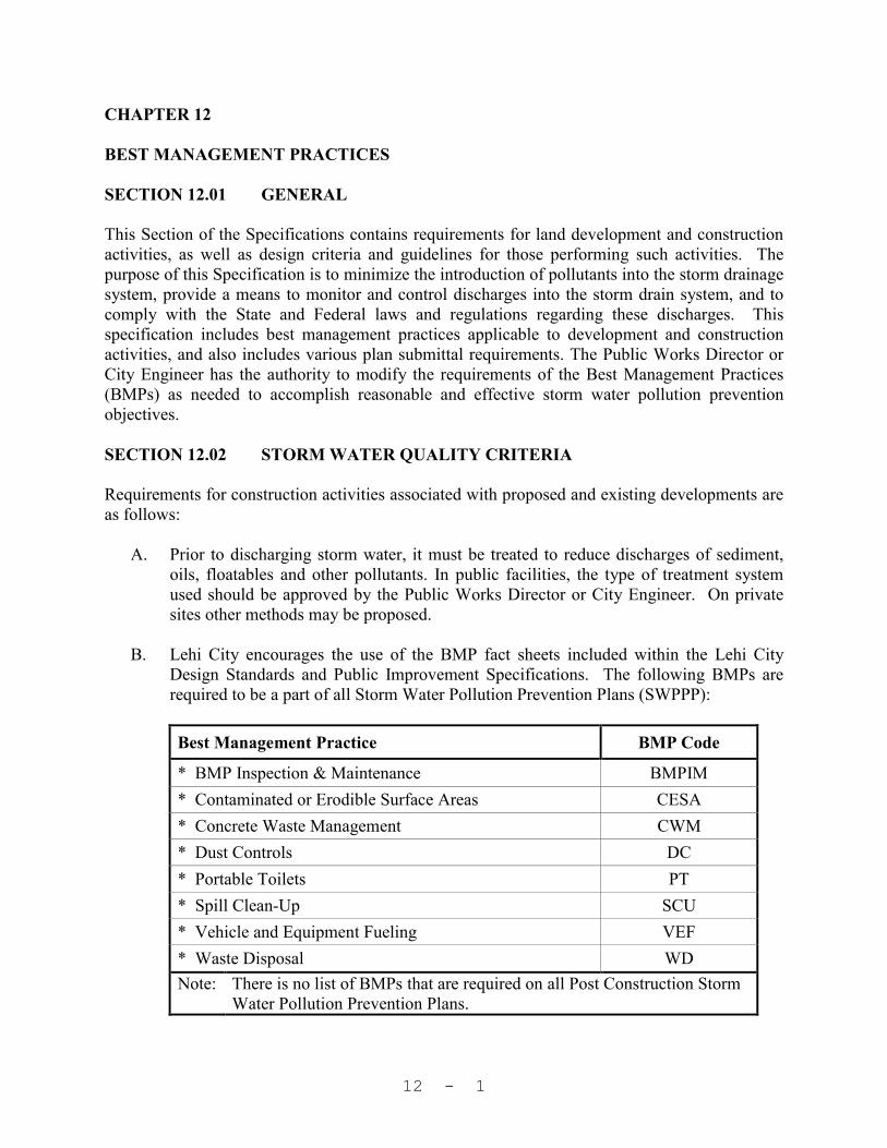
12 - 1
CHAPTER 12 BEST MANAGEMENT PRACTICES SECTION 12.01 GENERAL This Section of the Specifications contains requirements for land development and construction activities, as well as design criteria and guidelines for those performing such activities. The purpose of this Specification is to minimize the introduction of pollutants into the storm drainage system, provide a means to monitor and control discharges into the storm drain system, and to comply with the State and Federal laws and regulations regarding these discharges. This specification includes best management practices applicable to development and construction activities, and also includes various plan submittal requirements. The Public Works Director or City Engineer has the authority to modify the requirements of the Best Management Practices (BMPs) as needed to accomplish reasonable and effective storm water pollution prevention objectives. SECTION 12.02 STORM WATER QUALITY CRITERIA
Requirements for construction activities associated with proposed and existing developments are as follows:
A. Prior to discharging storm water, it must be treated to reduce discharges of sediment, oils, floatables and other pollutants. In public facilities, the type of treatment system used should be approved by the Public Works Director or City Engineer. On private sites other methods may be proposed.
B. Lehi City encourages the use of the BMP fact sheets included within the Lehi City
Design Standards and Public Improvement Specifications. The following BMPs are required to be a part of all Storm Water Pollution Prevention Plans (SWPPP):
Best Management Practice BMP Code
* BMP Inspection & Maintenance BMPIM
* Contaminated or Erodible Surface Areas CESA
* Concrete Waste Management CWM
* Dust Controls DC
* Portable Toilets PT
* Spill Clean-Up SCU
* Vehicle and Equipment Fueling VEF
* Waste Disposal WD
Note: There is no list of BMPs that are required on all Post Construction Storm Water Pollution Prevention Plans.

12 - 2
C. In addition to the required BMPs listed above, other BMPs from the Lehi City Design
Standards and Public Improvement Specifications that apply to a given development should be used (see table below). Lehi City also encourages the use of practices in addition to those contained in the Lehi City Design Standards and Public Improvement Specifications that may be suitable for a given development. Engineering judgment must be used in selecting BMPs for a given development.
Best Management Practice BMP Code
Brush or Rock Filter BRF
Catch Basin Cleaning CBC
Construction Road Stabilization CR
Construction Sequencing CS
Constructed Wetlands CW
Diversion Dike DD
Detention/Infiltration Device Maintenance DIDM
Erosion Control Blanket ECB
Extended Detention Basins EDB
Geotextiles and Mats GM
Grading Practices GP
Grassed Swales GS
Hydromulching HM
Inlet Protection – Concrete Block IPC
Inlet Protection – Excavated IPE
Inlet Protection – Gravel IPG
Inlet Protection – Silt Fence or Straw Bale IPS
Minimize Directly Connected Impervious Areas MDCIA
Material Storage MS
Mulching MU
Outlet Protection OP
Oil/Water Separators & Water Quality Inlets OWS
Preservation of Existing Vegetation PEV
Parking Lot Design PLD
Parking Lot Sweeping/Vacuuming PLSV
Rock Check Dams RCD
Riprap RR
Sediment Basin SB
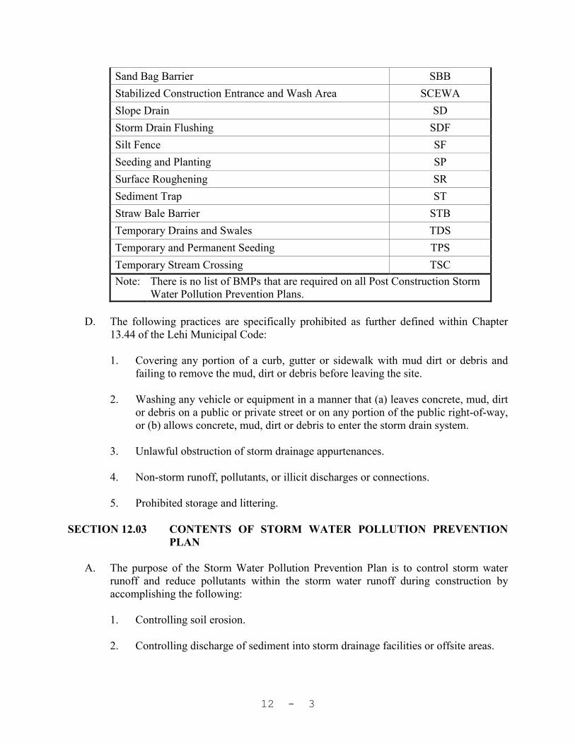
12 - 3
Sand Bag Barrier SBB
Stabilized Construction Entrance and Wash Area SCEWA
Slope Drain SD
Storm Drain Flushing SDF
Silt Fence SF
Seeding and Planting SP
Surface Roughening SR
Sediment Trap ST
Straw Bale Barrier STB
Temporary Drains and Swales TDS
Temporary and Permanent Seeding TPS
Temporary Stream Crossing TSC
Note: There is no list of BMPs that are required on all Post Construction Storm Water Pollution Prevention Plans.
D. The following practices are specifically prohibited as further defined within Chapter
13.44 of the Lehi Municipal Code:
1. Covering any portion of a curb, gutter or sidewalk with mud dirt or debris and failing to remove the mud, dirt or debris before leaving the site.
2. Washing any vehicle or equipment in a manner that (a) leaves concrete, mud, dirt
or debris on a public or private street or on any portion of the public right-of-way, or (b) allows concrete, mud, dirt or debris to enter the storm drain system.
3. Unlawful obstruction of storm drainage appurtenances. 4. Non-storm runoff, pollutants, or illicit discharges or connections. 5. Prohibited storage and littering.
SECTION 12.03 CONTENTS OF STORM WATER POLLUTION PREVENTION
PLAN A. The purpose of the Storm Water Pollution Prevention Plan is to control storm water
runoff and reduce pollutants within the storm water runoff during construction by accomplishing the following:
1. Controlling soil erosion. 2. Controlling discharge of sediment into storm drainage facilities or offsite areas.

12 - 4
3. Preventing illicit discharges into on-site soils, into storm drainage facilities or offsite areas.
4. Preventing uncontrolled discharge of storm water to adjacent property
5. Controlling dust and construction waste.
B. The Storm Water Pollution Prevention Plan is to be submitted with the site plans or improvement plans, and is to contain at least the following elements:
1. Existing and proposed contours as shown on the grading plan. 2. Existing and proposed storm drainage improvements.
3. Best management practices to accomplish the purpose of the plan should show the
following for each BMP specified, as applicable:
a. Location and extent of specified BMP. b. Timing of implementation. c. Duration of implementation. d. Any information in addition to or different from that shown on the BMP fact
sheet as necessary to employ the BMP on the site. 4. BMP Fact sheets or other descriptive material for all specified BMPs. 5. Show the following for all proposed vegetation or re-vegetation:
a. Location and type of vegetation or re-vegetation. b. Timing of vegetation or re-vegetation, possibly in terms of planting season
or number of days following commencement of grading. 6. Sequencing of construction activities and BMPs. 7. Name, address & telephone number of individual who has responsibility for
implementation and maintenance of the plan.
8. If there are lots within the area that are subject to the Hillside Preservation Zone (as defined in Section 12-A of the Lehi City Development Code), the plan also must meet the requirements of Section 12-A.030, and Sections 12-A.060 thru 12-A.100 of the Lehi City Development Code.
SECTION 12.04 CONTENTS OF POST CONSTRUCTION STORM WATER
POLLUTION PREVENTION PLAN A. The purpose of the Post Construction Storm Water Pollution Prevention Plan is to
control storm water runoff and reduce pollutants in storm water runoff after

12 - 5
construction is complete and the developed site is in operation. This is achieved by accomplishing the following:
1. Controlling soil erosion. 2. Controlling discharge of sediment into storm drainage facilities or off-site areas. 3. Preventing illicit discharges into on-site soils, storm drainage facilities or off-site
areas.
B. The Post Construction Storm Water Pollution Prevention Plan is to be submitted with the site plans or improvement plans. It shall be contained on a plan sheet of its own, rather than being a part of another plan sheet, and is to contain at least the following: 1. The site plan, including vicinity map, proposed contours, permanent storm
drainage improvements, and landscaping. 2. An indication as to which of the existing BMPs (shown on the Storm Water
Pollution Prevention Plan) may be modified or removed in conjunction with the BMPs being proposed as part of the Post Construction Storm Water Pollution Prevention Plan.
3. Best management practices to accomplish the purpose of the plan. Examples of
appropriate BMPs may include those addressing operation and maintenance of storm drainage quality control facilities, operation and maintenance of storm water discharge control facilities, maintenance of landscaping, good housekeeping practices, etc.
4. Show the following for each BMP specified:
a. Location and extent of specified BMPs, as appropriate. b. Detailed schedule of execution for each specified BMP, in terms of starting
time, duration, frequency, etc., as appropriate. c. Any information in addition to or different from that shown on the BMP fact
sheets as necessary to employ the BMPs on the site.
5. BMP fact sheets or other descriptive material for all specified BMPs. BMP fact sheets associated with the Post Construction Storm Water Pollution Prevention Plan are to be on a separate sheet from those that are part of the Storm Water Pollution Prevention Plan.
6. The following statement shall prominently appear on all Post Construction Storm
Water Pollution Prevention Plans:

12 - 6
The holders of the business license at this site (or owner of the lot over one acre if there is no business license) are responsible to perpetually follow this Post Construction Storm Water Pollution Prevention Plan. Failure to follow the plan may result in the City refusing to renew business licenses or take other action against the property owner. The objectives of the Plan are to:
1. Control soil erosion. 2. Control discharge of sediment into storm drainage facilities
or off-site areas. 3. Prevent illicit discharges into on-site soils, into storm
drainage facilities or offsite areas. If the objectives of the Plan are not being met, the site operator or owner shall make adjustments to the Plan as needed to accomplish its purposes. Lehi City encourages adjustments to the plan that enhance effective storm water management. However, significant reduction of practices contained in the plan is to be accomplished through formal modification of the plan and resubmission to the Development Review Committee for approval.
SECTION 12.05 REVIEW PROCEDURES FOR STORM WATER POLLUTION
PREVENTION PLAN AND POST CONSTRUCTION STORM WATER POLLUTION PREVENTION PLAN
The Storm Water Pollution Prevention Plan and the Post Construction Storm Water Pollution Prevention Plan will be submitted to Lehi City with the development plans. They will be reviewed along with the development plans, with storm water quantity and quality benefits in mind. The review procedure will be the same as for subdivision improvement plans and site plans, as outlined in Sections 10 & 11 of the Lehi City Development Code. SECTION 12.06 CONCLUSION Inasmuch as the construction and post construction related best management practices will generally be carried out by those in the private construction industry, they will be implemented as specified in the approved Storm Water Pollution Prevention and Post Construction Storm Water Pollution Prevention plans as development occurs. Refer to Chapter 13.44 of the Lehi City Municipal Code for additional guidance regarding the inspection and enforcement of specific BMP activities throughout the construction and post construction process. This section within the Lehi City Design Standards and Public Improvement Specifications satisfies, in part, two of the six minimum control measures established by the Storm Water Phase

12 - 7
II Rule. PART 7, SUMMARY OF BEST MANAGEMENT PRACTICES AND MEASURABLE GOALS, shows how the best management practices correlate with the six minimum control measures.