ledway street - horizontal tenon install
DESCRIPTION
LEDTRANSCRIPT

1 of 4 LPN00216X0001A0
LEDway® SeriesLED Street Light
Includes: STR-LWY-HT, HT-IP
INSTALLATION INSTRUCTIONSIMPORTANT SAFEGUARDSWhen using electrical equipment, basic safety precautions should always be followed including the following:
READ AND FOLLOW ALL SAFETY INSTRUCTIONS1. To avoid the possibility of electrical shock, turn off power supply before installation or servicing. Installation and servicing
should be performed by qualified personnel.2. When closing cover of fixture, be sure all wires are inside housing to avoid pinching wires.3. If NEMA photo control is installed refer to NEMA Receptacle section for instructions.4. Product must be installed in accordance with NEC or your local electrical code. If you are not familiar with these codes and
requirements, consult a qualified electrician.5. If mounting bolts are completely removed in the field they should be hand threaded (prior to use of power tools) to ensure
proper engagement of the thread when re-installing. Failure to pre-start threads may result in cross-threading or stripping of the bolts during reinstallation.
SAVE THESE INSTRUCTIONS FOR FUTURE REFERENCE
TO INSTALL:
STANDARD MOUNTING
STEP 1:DO NOT remove splashguard from fixture. If mounting fixture to 1.25 IP pipe (1.66 O.D.), there is no need to modify the splashguard. If mounting fixture onto 2.0 IP pipe (2.38 O.D.), remove the knockout of the splashguard thru the rear opening of the fixture while the fixture is closed. See Figure 2.
STEP 2:To open cover, hold fixture by heat sink with the light bars facing down and hinges facing away. Simultaneously pull latches and the cover to swing open. Splashguard may dislodge from fixture, but should be repositioned once ready to mount. See Figure 1.
STEP 3:Slide fixture on to pole through opening on the rear of housing and through splashguard.
STEP 4:To level fixture, use bubble level located inside housing. Adjust leveling of fixture from side to side. To level from front to back, slide pole to different step in upper housing. Each step changes the angle in 2.5° increments. See Figure 3.
STEP 5:Once desired position is achieved, tighten (2) mounting bolts to the appropriate torque values specified in TABLE 1. See Figure 1 (use 9/16" wrench socket).IMPORTANT - DO NOT exceed these torque levels on the mount bolts. Exceeding recommended torque value resulting in excessive deformation of mounting bracket will cause stripping of mount hardware which could lead to an unsafe mounting condition.
STEP 6:Reference “Electrical Connections” section for completing electrical connections.
1 Heatsink
Mounting ClampBracket
Mounting Clamp (2)See Table 1
Cover in Open Position
Pole
Driver
Pipe Perimeter (IP66 Only) Sealing Gasket/Plate
OR
Splashguard
Cover in Open Position
Terminal Block
TABLE 1
2
3
Fitter Pipe end
Final Stop Boss
2nd Stop Boss
3rd Stop Boss
TORQUE VALUES
PipeSize Pipe Position Bolt Torque
Required (in-lbs)Bolt Torque
Required (N-m)
1.66 in O.D.
+5.0 degrees tilt 200 22
+2.5 degrees tilt 200 22
0 degrees (no tilt) 200 22
-2.5 degrees tilt 200 22
-5.0 degrees tilt 200 22
2.38 in O.D.
+5.0 degrees tilt 200 22
+2.5 degrees tilt 200 22
0 degrees (no tilt) 200 22
-2.5 degrees tilt 200 22
-5.0 degrees tilt 200 22

2 of 4 LPN00216X0001A0
STANDARD MOUNTING - IP66 WEATHER SEALED
NOTE: Follow step instructions described in the “Standard Mounting” section, disregarding the splashguard, and following these additional steps:
STEP 1:Before sliding fixture on pipe, pull supply wires and ground wire (if necessary) from pipe thru small sealed holes in sealing grommet. See Figure 4.
STEP 2:Slide sealing grommet onto end of pipe. See Figure 4.
STEP 3:Fully seat the sealing grommet by forcing the compression cap over the sealing grommet, until fully engaged. (This may require slight lubrication) See Figure 4.
STEP 4:Carefully, slide fixture onto pipe thru the opening on the rear of the housing and thru pipe perimeter sealing gasket/plate.
STEP 5:This fixture is designed for mounting to 2.38" O.D. pipe. If your application requires 1.66" O.D. pipe, the Sealing Grommet and Compression Cap provided in the fixture will need to be replaced with the 1.66" O.D. parts (parts sold separately, Cat. No. XAXIL125IP). See Figure 4.
ELECTRICAL CONNECTIONS PHASE TO NEUTRAL WIRING
STEP 1:Make the following Electrical Connections:
a. Connect supply ground conductor to green wire position of the terminal block within the LED Driver Enclosure.
b. Connect supply voltage conductor to black wire position of the terminal block within the LED Driver Enclosure.
c. Connect supply neutral conductor to the white wire position of the terminal block within the LED Driver Enclosure.
STEP 2:Push excess supply wires into pole.
STEP 3:Close cover by firmly pushing cover towards fixture, making sure that no wires are pinched and latches are fully engaged.
STEP 4:Insulate all electrical connections with wire nuts suitable for at least 90°C
ELECTRICAL CONNECTIONS PHASE TO NEUTRAL WIRING
STEP 1:Make the following Electrical Connections:
a. Connect supply ground conductor to green wire position of the terminal block within the LED Driver Enclosure.
b. Connect supply L1 (Hot) conductor to black wire position of the terminal block within the LED Driver Enclosure.
c. Connect supply L2 (Hot) conductor to the white wire position of the terminal block within the LED Driver Enclosure.
STEP 2:Push excess supply wires into pole.
STEP 3:Close cover by firmly pushing cover towards fixture, making sure that no wires are pinched and latches are fully engaged.
STEP 4:Insulate all electrical connections with wire nuts suitable for at least 90°C
LINEOR LINE 1
GREEN
LINE-BLACKLINE-BLACK
GROUND-GREEN
NEUTRAL-WHITECOMMON-WHITE
NEUTRALOR LINE 2
SU
PP
LY W
IRIN
G
FIXTURE WIRING
LE
D D
RIV
ER
(S)
TERMINAL BLOCK
N
G
L
GROUND
LINE-BLACK
GROUND-GREEN
COMMON-WHITELINE (L2)
SU
PP
LY W
IRIN
G
FIXTURE WIRING
LE
D D
RIV
ER
(S)
TERMINAL BLOCK
N
G
LLINE (L1)
20
8, 2
40
, 48
0V
NEMA RECEPTACLE (OPTIONAL)
STEP 1:DO NOT loosen/tighten flat head screws for the NEMA receptacle.
STEP 2:Rotational adjustment of the photo control is tool-less.
STEP 3:Engage/install photo control into NEMA receptacle on top of the fixture.
STEP 4:Firmly rotate photo-control with its photo-eye approximately in the ‘N’ north direction. Some photo-controls operate best somewhere between NW and NE.
4

3 of 4 LPN00216X0001A0
ADJUSTING LIGHT OUTPUT
NOTE: It is possible to switch the fixture in the field to obtain less or more light output. The fixture leaves the factory with the LED driver(s) wired at one of the following:
• 350mA = -UH (Figure 6)• 525mA = -U, -UC (Figure 5)• 700mA = -UD (Figure 7)
For more or less light output, follow the instructions below.
TO SWITCH FROM 525mA TO 350mA
STEP 1:Locate the lever nut containing the violet lead(s) from the Driver(s) and the yellow lead from the Tri-Tap Module.
STEP 2:Remove the yellow wire by lifting the orange lever.
STEP 3:Locate the lever nut containing the orange wire from the Tri-Tap Module and remove the wire by lifting the orange lever.
STEP 4:Place the orange wire into the lever nut containing the violet lead(s) from the Driver(s) and snap down the orange lever to secure.
STEP 5:Place the yellow lead from the Tri-Tap Module in to the empty lever nut and snap down the orange lever to secure.
TO SWITCH FROM 525mA TO 700mA
STEP 1:Locate the lever nut containing the violet lead(s) from the Driver(s) and the yellow lead from the Tri-Tap Module.
STEP 2:Remove the yellow wire by lifting the orange lever.
STEP 3:Locate the lever nut containing the blue wire from the Tri-Tap Module and remove the wire by lifting the orange lever.
STEP 4:Place the blue wire into the lever nut containing the violet lead(s) from the Driver(s) and snap down the orange lever to secure.
STEP 5:Place the yellow lead from the Tri-Tap Module in to the empty lever nut and snap down the orange lever to secure.
CAUTION - By switching the LED fixture to have more light output, the fixture will have also have a greater amp draw. Refer to fixture label for the amp draw at 700 mA.
LED
LIGH
T B
AR
(S)LE
D LIG
HT
BA
R(S)
DRIVER WIRED FOR 525mA (STANDARD)
LED DRIVER INPUT LED DRIVER OUTPUT
DRIVER 1
DRIVER 2
TRI-TAPMODULE
BLACK BLUE BLACK
WHITERED RED
ORANGE 350mA
YELLOW 525mA
GRAY
BLUE 700mA
BLACKBLUE BLACK
WHITE RED RED
GR
AY
GR
AY
VIO
LET
VIO
LET
LE
D L
IGH
T B
AR
(S)
LE
D L
IGH
T B
AR
(S)
DRIVER WIRED FOR 350mA (LESS LIGHT OUTPUT)
LED DRIVER INPUT LED DRIVER OUTPUT
DRIVER 1
DRIVER 2
TRI-TAPMODULE
BLACK BLUE BLACK
WHITERED RED
ORANGE 350mA
YELLOW 525mA
GRAY
BLUE 700mA
BLACKBLUE BLACK
WHITE RED RED
GR
AY
GR
AY
VIO
LE
TV
IOL
ET
LE
D L
IGH
T B
AR
(S)
LE
D L
IGH
T B
AR
(S)
DRIVER WIRED FOR 700mA (MORE LIGHT OUTPUT)
LED DRIVER INPUT LED DRIVER OUTPUT
DRIVER 1
DRIVER 2
TRI-TAPMODULE
BLACK BLUE BLACK
WHITERED RED
ORANGE 350mA
YELLOW 525mA
GRAY
BLUE 700mA
BLACKBLUE BLACK
WHITE RED RED
GR
AY
GR
AY
VIO
LE
TV
IOL
ET
5
6
7
4 of 4 LPN00216X0001A0
www.cree.com/lighting
© 2013 Cree, Inc. All rights reserved. For informational purposes only. Content is subject to change. See www.cree.com/lighting/products/warranty for warranty and specifications. Cree®, the Cree logo, and LEDway® are registered trademarks.
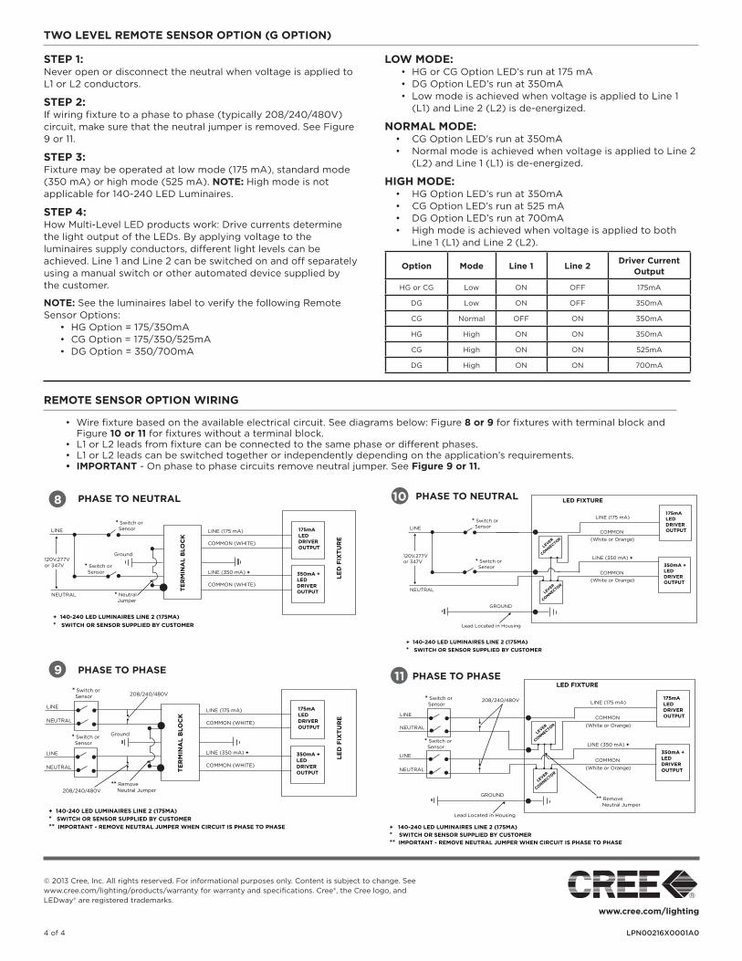
TWO LEVEL REMOTE SENSOR OPTION (G OPTION)
STEP 1:Never open or disconnect the neutral when voltage is applied to L1 or L2 conductors.
STEP 2:If wiring fixture to a phase to phase (typically 208/240/480V) circuit, make sure that the neutral jumper is removed. See Figure 9 or 11.
STEP 3:Fixture may be operated at low mode (175 mA), standard mode (350 mA) or high mode (525 mA). NOTE: High mode is not applicable for 140-240 LED Luminaires.
STEP 4:How Multi-Level LED products work: Drive currents determine the light output of the LEDs. By applying voltage to the luminaires supply conductors, different light levels can be achieved. Line 1 and Line 2 can be switched on and off separately using a manual switch or other automated device supplied by the customer.
NOTE: See the luminaires label to verify the following Remote Sensor Options:
• HG Option = 175/350mA• CG Option = 175/350/525mA • DG Option = 350/700mA
LOW MODE: • HG or CG Option LED’s run at 175 mA • DG Option LED’s run at 350mA• Low mode is achieved when voltage is applied to Line 1
(L1) and Line 2 (L2) is de-energized.
NORMAL MODE: • CG Option LED’s run at 350mA• Normal mode is achieved when voltage is applied to Line 2
(L2) and Line 1 (L1) is de-energized.
HIGH MODE: • HG Option LED’s run at 350mA• CG Option LED’s run at 525 mA• DG Option LED’s run at 700mA• High mode is achieved when voltage is applied to both
Line 1 (L1) and Line 2 (L2).
Option Mode Line 1 Line 2Driver Current
Output
HG or CG Low ON OFF 175mA
DG Low ON OFF 350mA
CG Normal OFF ON 350mA
HG High ON ON 350mA
CG High ON ON 525mA
DG High ON ON 700mA
LE
D F
IXT
UR
E
175mALEDDRIVEROUTPUT
350mA +LEDDRIVEROUTPUT
* Switch or Sensor LINE (175 mA)
COMMON (WHITE)
LINE (350 mA) +
COMMON (WHITE)
* Switch or Sensor
Ground
* Neutral Jumper
LINE
NEUTRAL
120V,277V or 347V
TE
RM
INA
L B
LOC
K
+ 140-240 LED LUMINAIRES LINE 2 (175MA)
* SWITCH OR SENSOR SUPPLIED BY CUSTOMER
PHASE TO NEUTRAL
LE
D F
IXT
UR
E
175mALEDDRIVEROUTPUT
350mA +LEDDRIVEROUTPUT
LINE (175 mA)
COMMON (WHITE)
LINE (350 mA) +
COMMON (WHITE)
* Switch or Sensor
Ground
** Remove Neutral Jumper
NEUTRAL
208/240/480V
TE
RM
INA
L B
LOC
K
+ 140-240 LED LUMINAIRES LINE 2 (175MA)* SWITCH OR SENSOR SUPPLIED BY CUSTOMER** IMPORTANT - REMOVE NEUTRAL JUMPER WHEN CIRCUIT IS PHASE TO PHASE
LINE
* Switch or Sensor
NEUTRAL
LINE
208/240/480V
LED FIXTURE
175mALEDDRIVEROUTPUT
350mA +LEDDRIVEROUTPUT
* Switch or Sensor
LINE (175 mA)
LINE (350 mA) +
COMMON
(White or Orange)
* Switch or Sensor
GROUND
LINE
NEUTRAL
120V,277V or 347V
+ 140-240 LED LUMINAIRES LINE 2 (175MA)* SWITCH OR SENSOR SUPPLIED BY CUSTOMER
COMMON
(White or Orange)LEVER
CONNECTOR
LEVER
CONNECTOR
Lead Located in Housing
LED FIXTURE
175mALEDDRIVEROUTPUT
350mA +LEDDRIVEROUTPUT
LINE (175 mA)
LINE (350 mA) +
COMMON
(White or Orange)
GROUND
COMMON
(White or Orange)LEVER
CONNECTOR
LEVER
CONNECTOR
* Switch or Sensor
NEUTRAL
208/240/480V
LINE
* Switch or Sensor
NEUTRAL
LINE
+ 140-240 LED LUMINAIRES LINE 2 (175MA)* SWITCH OR SENSOR SUPPLIED BY CUSTOMER** IMPORTANT - REMOVE NEUTRAL JUMPER WHEN CIRCUIT IS PHASE TO PHASE
** Remove Neutral Jumper
Lead Located in Housing
PHASE TO NEUTRAL8
9
10
PHASE TO PHASE11PHASE TO PHASE
REMOTE SENSOR OPTION WIRING
• Wire fixture based on the available electrical circuit. See diagrams below: Figure 8 or 9 for fixtures with terminal block and Figure 10 or 11 for fixtures without a terminal block.
• L1 or L2 leads from fixture can be connected to the same phase or different phases.• L1 or L2 leads can be switched together or independently depending on the application’s requirements.• IMPORTANT - On phase to phase circuits remove neutral jumper. See Figure 9 or 11.