led control
DESCRIPTION
ArduinoTRANSCRIPT
LedControl DocumentationRelease 1.0.0
Eberhard Fahle
January 29, 2015


Contents
1 Hardware and schematics 31.1 Wiring . . . . . . . . . . . . . . . . . . . . . . . . . . . . . . . . . . . . . . . . . . . . . . . . . . 31.2 MAX7219 vs. MAX7221 . . . . . . . . . . . . . . . . . . . . . . . . . . . . . . . . . . . . . . . . . 81.3 Selecting RSet . . . . . . . . . . . . . . . . . . . . . . . . . . . . . . . . . . . . . . . . . . . . . . 81.4 Power supply issues . . . . . . . . . . . . . . . . . . . . . . . . . . . . . . . . . . . . . . . . . . . 9
2 The Software library 132.1 Creating a LedControl instance . . . . . . . . . . . . . . . . . . . . . . . . . . . . . . . . . . . . . 132.2 Power saving mode . . . . . . . . . . . . . . . . . . . . . . . . . . . . . . . . . . . . . . . . . . . . 152.3 Limiting the number of digits (ScanLimit) . . . . . . . . . . . . . . . . . . . . . . . . . . . . . . . 152.4 Setting display brightness . . . . . . . . . . . . . . . . . . . . . . . . . . . . . . . . . . . . . . . . 162.5 Device initialization . . . . . . . . . . . . . . . . . . . . . . . . . . . . . . . . . . . . . . . . . . . 162.6 Clearing the display . . . . . . . . . . . . . . . . . . . . . . . . . . . . . . . . . . . . . . . . . . . 172.7 Controlling a Led matrix . . . . . . . . . . . . . . . . . . . . . . . . . . . . . . . . . . . . . . . . . 172.8 Control 7-Segment displays . . . . . . . . . . . . . . . . . . . . . . . . . . . . . . . . . . . . . . . 222.9 Commented demos for the library . . . . . . . . . . . . . . . . . . . . . . . . . . . . . . . . . . . . 242.10 Sourcecode and download . . . . . . . . . . . . . . . . . . . . . . . . . . . . . . . . . . . . . . . . 24
3 LedControl-library demos 273.1 Led matrix . . . . . . . . . . . . . . . . . . . . . . . . . . . . . . . . . . . . . . . . . . . . . . . . 273.2 7-segment display . . . . . . . . . . . . . . . . . . . . . . . . . . . . . . . . . . . . . . . . . . . . 293.3 Cascaded devices . . . . . . . . . . . . . . . . . . . . . . . . . . . . . . . . . . . . . . . . . . . . . 31
4 Known bugs 33
5 Revision History 35
6 Feedback 37
7 License (The software) 39
i

ii
LedControl Documentation, Release 1.0.0
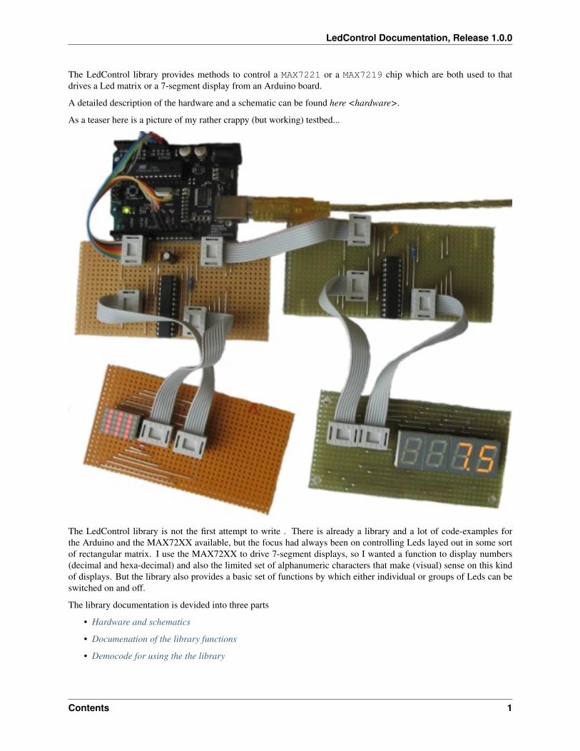
The LedControl library provides methods to control a MAX7221 or a MAX7219 chip which are both used to thatdrives a Led matrix or a 7-segment display from an Arduino board.
A detailed description of the hardware and a schematic can be found here <hardware>.
As a teaser here is a picture of my rather crappy (but working) testbed...
The LedControl library is not the first attempt to write . There is already a library and a lot of code-examples forthe Arduino and the MAX72XX available, but the focus had always been on controlling Leds layed out in some sortof rectangular matrix. I use the MAX72XX to drive 7-segment displays, so I wanted a function to display numbers(decimal and hexa-decimal) and also the limited set of alphanumeric characters that make (visual) sense on this kindof displays. But the library also provides a basic set of functions by which either individual or groups of Leds can beswitched on and off.
The library documentation is devided into three parts
• Hardware and schematics
• Documenation of the library functions
• Democode for using the the library
Contents 1
LedControl Documentation, Release 1.0.0
2 Contents
CHAPTER 1
Hardware and schematics
The library supports two Maxim IC display drivers, the MAX7219 and the MAX7221. Both circuits can drive up 64individual Led’s, or 7-segment displays with 8 digits. The drivers implement a SPI compatible slave interface that canbe controlled from the Arduino using only 3 digital output pins. An datasheet for the MAX72XX is available from theMaxim homepage. Both drivers provide identical functions so I will use the generic term MAX72XX for the MAX7221and the MAX7219. Both chips are still in production as of March 2014.
This section of the documentation focuses on building the external hardware, and should be seen as supplement to theoriginal datasheet . For a basic understanding I suggest you have a look at the datasheet first and the read this sectionfor Arduino specific information
1.1 Wiring
Here is a basic schematic for a MAX72XX, showing only the data signals coming from the Arduino.
3

LedControl Documentation, Release 1.0.0
4 Chapter 1. Hardware and schematics
LedControl Documentation, Release 1.0.0
Besides the MAX72XX itself and the Leds there are only 3 external components: two capacitors (C1; C2) and a resistor(RSet).
The capacitors are there to supress noise signals introduced through the power-supply lines. By no means these 2capacitors should be ommitted, as it might lead to sporadic or permanent malfunctions. These types of errors arereally hard to track down. Both capacitors must be placed as near as possible to the V+ and the Gnd pins of theMAX72XX.
The resistor RSet is responsible for setting an upper limit on the current that is fed into the Leds. Selecting the correctresistor value might not be trivial. There is an in-depth discussion on this later.
The MAX72XX has to be powered with +5V. For a single Led-matrix it is possible to use the +5V supply from theArduino-board. If you add more than one matrix to the Arduino you will probably need an external power-supply.More on this in section Power supply issues.
1.1.1 Arduino interface
The Gnd-Pins of the MAX72XX have to be connected to one of the Gnd-Pins on the Arduino board. That makes bothcircuits work on the same voltage-level. The positive power-supply pins (+5V/Vcc) can directly be connected to theArduino-board only for a limited number of Led’s.(See Power supply issues for details.)
The three signal lines (DIn,CLK,Load(/CS)) have to be connected to three digital outputs on the Arduino board.It depends on the software which Arduino pins have to be used. For the exact pin-numbers you have to refer to thesoftware documentation of the library or the example code on which you build your project. With most of the librariesfor the MAX72XX you are free to choose any pins you like.
If you read the datasheet for the MAX72XX you know that the drivers can be cascaded by simply connecting the signalDOut from one chip to DIn on the next chip. The signals Clk and Load(/CS) have to be connected in parallelto each MAX72XX. There is no strict limit as to how many drivers can be cascaded that way. But the SPI-interfaceis not capable of any error checking on the transmitted data, so you are already limited with the length of the cablesthat run from one MAX72XX to the next one. If your cables have to be much longer than 10cm (4 inch) between eachMAX72XX you ‘’might” already run into trouble.
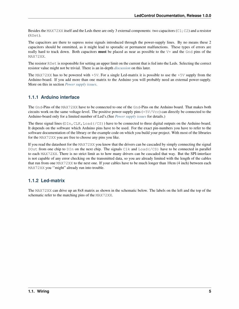
1.1.2 Led-matrix
The MAX72XX can drive up an 8x8 matrix as shown in the schematic below. The labels on the left and the top of theschematic refer to the matching pins of the MAX72XX.
1.1. Wiring 5
LedControl Documentation, Release 1.0.0
You can build your own matrix out of individual Leds, but there are also pre-wired ones available. They can be directlyconnected to the MAX72XX. Some are arranged as ‘’column cathode” and some are ‘’column anode” (as in the diagramabove). Either type will work but you must connect the anodes to the Seg lines and cathodes to the Dig lines.
1.1.3 7-segment displays
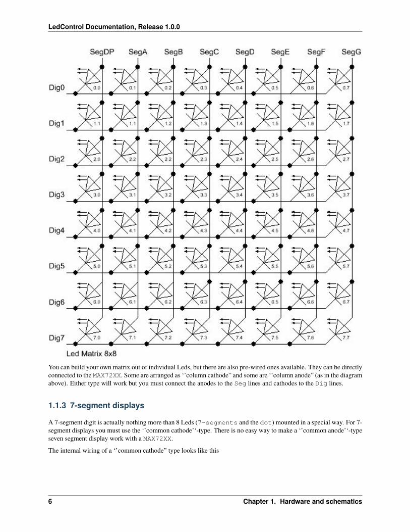
A 7-segment digit is actually nothing more than 8 Leds (7-segments and the dot) mounted in a special way. For 7-segment displays you must use the ‘’common cathode’‘-type. There is no easy way to make a ‘’common anode’‘-typeseven segment display work with a MAX72XX.
The internal wiring of a ‘’common cathode” type looks like this
6 Chapter 1. Hardware and schematics
LedControl Documentation, Release 1.0.0
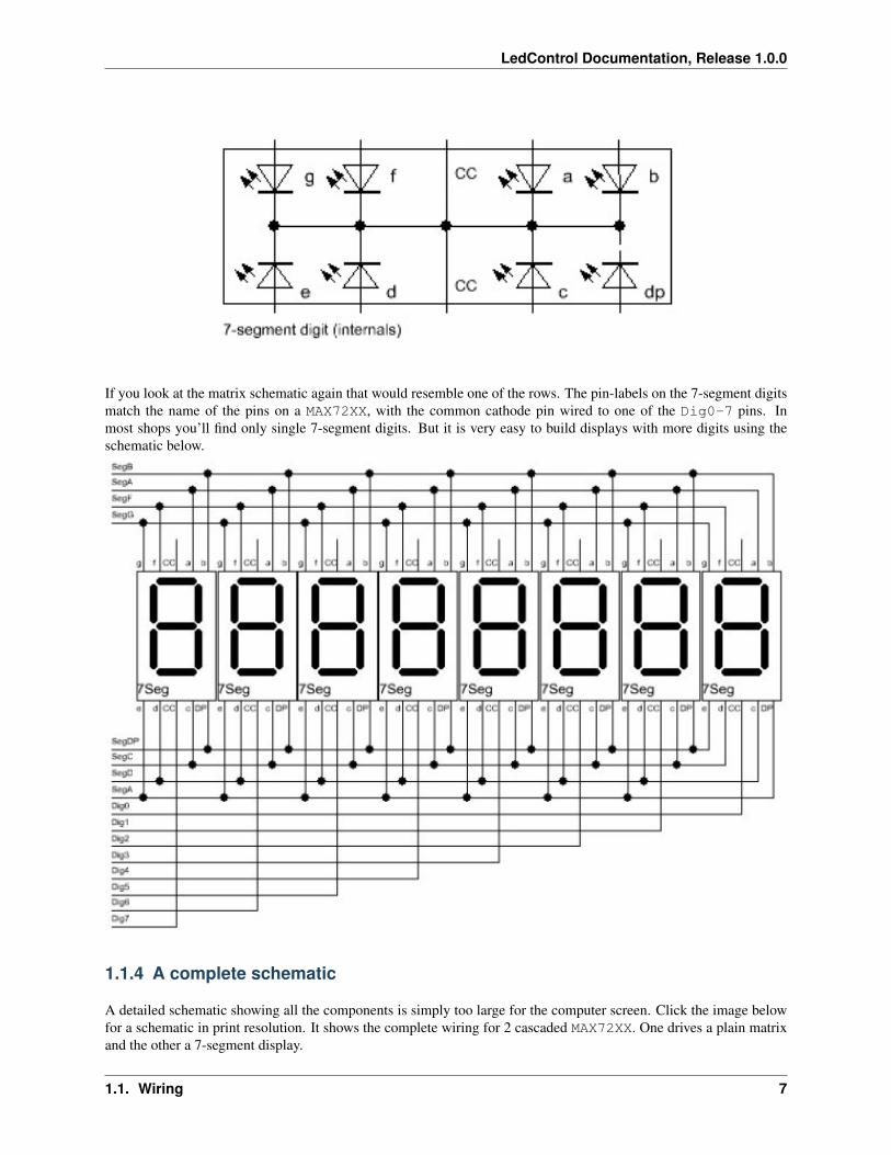
If you look at the matrix schematic again that would resemble one of the rows. The pin-labels on the 7-segment digitsmatch the name of the pins on a MAX72XX, with the common cathode pin wired to one of the Dig0-7 pins. Inmost shops you’ll find only single 7-segment digits. But it is very easy to build displays with more digits using theschematic below.
1.1.4 A complete schematic
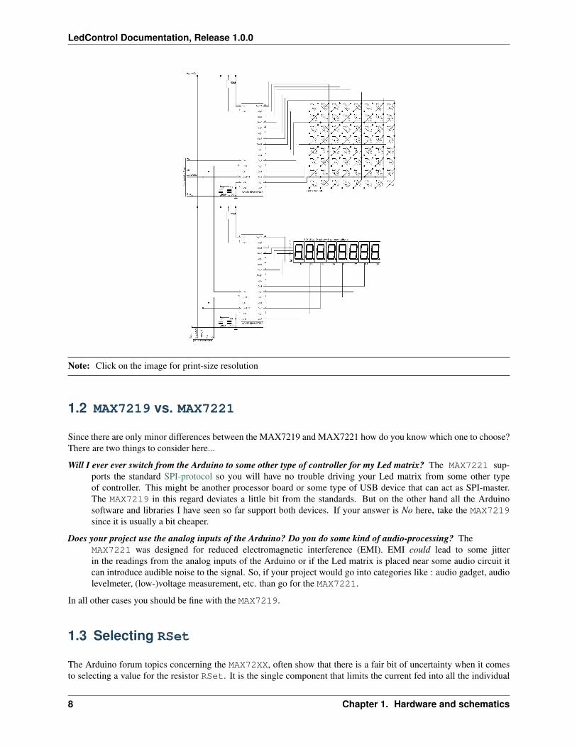
A detailed schematic showing all the components is simply too large for the computer screen. Click the image belowfor a schematic in print resolution. It shows the complete wiring for 2 cascaded MAX72XX. One drives a plain matrixand the other a 7-segment display.
1.1. Wiring 7
LedControl Documentation, Release 1.0.0
Note: Click on the image for print-size resolution
1.2 MAX7219 vs. MAX7221
Since there are only minor differences between the MAX7219 and MAX7221 how do you know which one to choose?There are two things to consider here...
Will I ever ever switch from the Arduino to some other type of controller for my Led matrix? The MAX7221 sup-ports the standard SPI-protocol so you will have no trouble driving your Led matrix from some other typeof controller. This might be another processor board or some type of USB device that can act as SPI-master.The MAX7219 in this regard deviates a little bit from the standards. But on the other hand all the Arduinosoftware and libraries I have seen so far support both devices. If your answer is No here, take the MAX7219since it is usually a bit cheaper.
Does your project use the analog inputs of the Arduino? Do you do some kind of audio-processing? TheMAX7221 was designed for reduced electromagnetic interference (EMI). EMI could lead to some jitterin the readings from the analog inputs of the Arduino or if the Led matrix is placed near some audio circuit itcan introduce audible noise to the signal. So, if your project would go into categories like : audio gadget, audiolevelmeter, (low-)voltage measurement, etc. than go for the MAX7221.
In all other cases you should be fine with the MAX7219.
1.3 Selecting RSet
The Arduino forum topics concerning the MAX72XX, often show that there is a fair bit of uncertainty when it comesto selecting a value for the resistor RSet. It is the single component that limits the current fed into all the individual
8 Chapter 1. Hardware and schematics
LedControl Documentation, Release 1.0.0
Leds. While some people seem to think of this resistor as a way to control the brightness of the Leds, its real purposeis to protect the MAX72XX and the Leds from exessive currents. Setting the brightness of the display can and shouldbe done from software.
To find out the correct value for RSet you need the datasheet for the MAX72XX and the datasheet for the Ledmatrixor 7-segment display you’re going to use.
From the datasheet of your Led’s you will need to know two values
DC forward current the maximum current that is allowed to go through the Led without damaging it in thelong run.
Forward voltage the voltage at which the Led operates.
While the Forward voltage is a fixed value which depends (mostly) on the color of the Led, you have to limitthe current going through the Led with resistor RSet. Since DC forward current is a maximum value, which isnot be exceeded, you should settle for a slightly lower current. Standard Led’s and 7-segment displays are often ratedwith a DC forward current of 25-30mA. Limiting to 20mA would make a good choice.
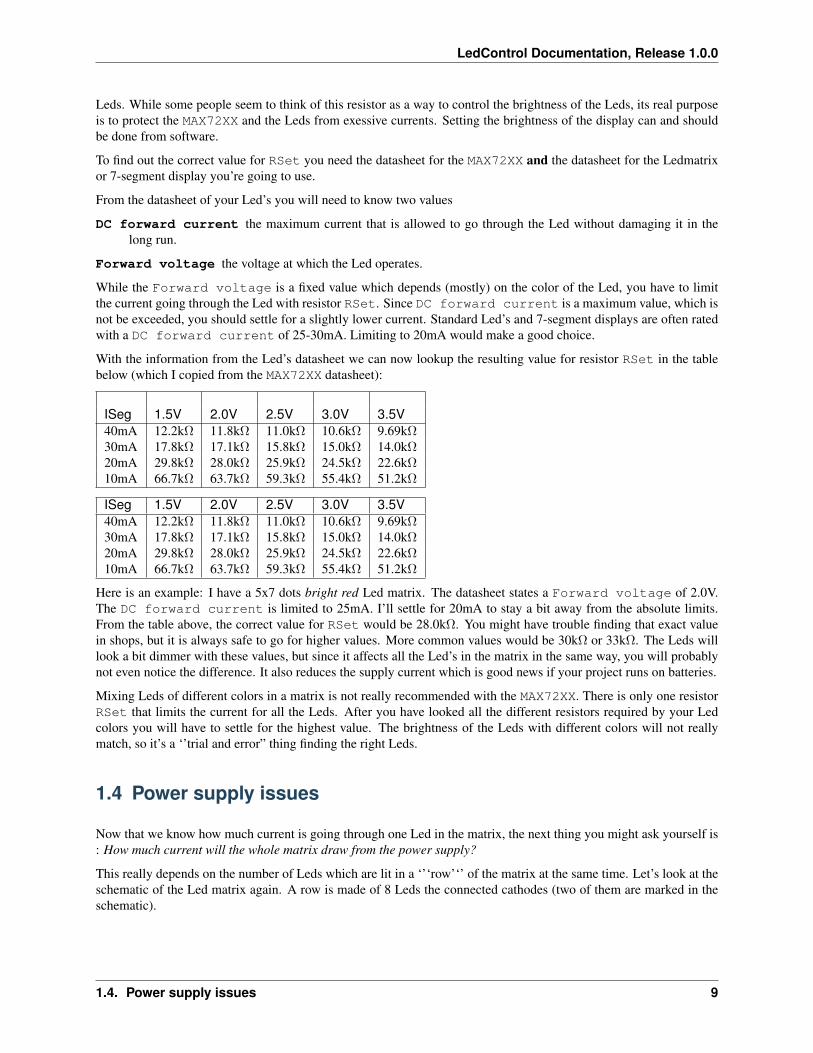
With the information from the Led’s datasheet we can now lookup the resulting value for resistor RSet in the tablebelow (which I copied from the MAX72XX datasheet):
ISeg 1.5V 2.0V 2.5V 3.0V 3.5V40mA 12.2kΩ 11.8kΩ 11.0kΩ 10.6kΩ 9.69kΩ30mA 17.8kΩ 17.1kΩ 15.8kΩ 15.0kΩ 14.0kΩ20mA 29.8kΩ 28.0kΩ 25.9kΩ 24.5kΩ 22.6kΩ10mA 66.7kΩ 63.7kΩ 59.3kΩ 55.4kΩ 51.2kΩ
ISeg 1.5V 2.0V 2.5V 3.0V 3.5V40mA 12.2kΩ 11.8kΩ 11.0kΩ 10.6kΩ 9.69kΩ30mA 17.8kΩ 17.1kΩ 15.8kΩ 15.0kΩ 14.0kΩ20mA 29.8kΩ 28.0kΩ 25.9kΩ 24.5kΩ 22.6kΩ10mA 66.7kΩ 63.7kΩ 59.3kΩ 55.4kΩ 51.2kΩ
Here is an example: I have a 5x7 dots bright red Led matrix. The datasheet states a Forward voltage of 2.0V.The DC forward current is limited to 25mA. I’ll settle for 20mA to stay a bit away from the absolute limits.From the table above, the correct value for RSet would be 28.0kΩ. You might have trouble finding that exact valuein shops, but it is always safe to go for higher values. More common values would be 30kΩ or 33kΩ. The Leds willlook a bit dimmer with these values, but since it affects all the Led’s in the matrix in the same way, you will probablynot even notice the difference. It also reduces the supply current which is good news if your project runs on batteries.
Mixing Leds of different colors in a matrix is not really recommended with the MAX72XX. There is only one resistorRSet that limits the current for all the Leds. After you have looked all the different resistors required by your Ledcolors you will have to settle for the highest value. The brightness of the Leds with different colors will not reallymatch, so it’s a ‘’trial and error” thing finding the right Leds.
1.4 Power supply issues
Now that we know how much current is going through one Led in the matrix, the next thing you might ask yourself is: How much current will the whole matrix draw from the power supply?
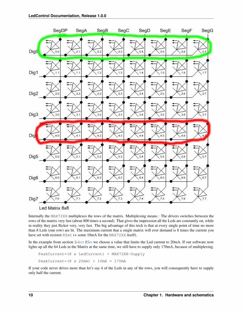
This really depends on the number of Leds which are lit in a ‘’‘row’‘’ of the matrix at the same time. Let’s look at theschematic of the Led matrix again. A row is made of 8 Leds the connected cathodes (two of them are marked in theschematic).
1.4. Power supply issues 9
LedControl Documentation, Release 1.0.0
Internally the MAX72XX multiplexes the rows of the matrix. Multiplexing means : The drivers switches between therows of the matrix very fast (about 800 times a second). That gives the impression all the Leds are constantly on, whilein reality they just flicker very, very fast. The big advantage of this trick is that at every single point of time no morethan 8 Leds (one row) are lit. The maximum current that a single matrix will ever demand is 8 times the current youhave set with resistor RSet (+ some 10mA for the MAX72XX itself).
In the example from section Select RSet we choose a value that limits the Led current to 20mA. If our software nowlights up all the 64 Leds in the Matrix at the same time, we still have to supply only 170mA, because of multiplexing.
PeakCurrent=(8 x LedCurrent) + MAX72XX-Supply
PeakCurrent=(8 x 20mA) + 10mA = 170mA
If your code never drives more than let’s say 4 of the Leds in any of the rows, you will consequently have to supplyonly half the current.
10 Chapter 1. Hardware and schematics
LedControl Documentation, Release 1.0.0
1.4.1 Powering the Leds from the USB-port
Depending on the type of USB-hub you’re using, there are different limits as to how much current can be drawn froma single USB-port.
The root hub This is the USB-hub on your computer. On a desktop machine it will deliver up to 500mA on everyUSB-port. Some notebooks implement power saving strategies that limit the maximum current to 100mA assoon as it is unplugged from mains and runs on batteries.
External self-powered hub This kind of USB-hub brings its on power-supply unit. Like the root hub, you can draw500mA from each port. Some of these self-powered hubs supply the current, even when your computer is turnedoff or you unplug the hub itself. But sadly this is often not even mentioned in the datasheet of the hub. I have3 self-powered hubs. One switches the USB-ports off when my machine shuts down or I unplug the hub. Theother two don’t care about this, the 5V supply on the USB-port is always alive.
External bus-powered hub These hubs don’t bring their own power-supply and therefore they will deliver not morethan 100mA per USB-port. This type of hub is not really suitable for any Ardunino project with externalhardware to be powered from USB.
Of the three, only the root and self-powered hubs that supply up to 500mA are recommended. As was said before theactual current your hardware draws depends very much on the software you write.
Here is the worst-case scenario: There are times when all 64 Leds are on at the same time and you selected resistorRSet that allows a current of 20mA per Led. That will add up to a maximum current of 170mA per matrix. Withtwo of these matrices you’re at 340mA. Now add another 40mA for the arduino itself and you’ll end up with 380mA.There is not enough headroom for adding third matrix in this case.
But if you light up only a single Led at any time, your maximum current is at 30mA. You can easily drive 15 MAX72XXand the Arduino from a 500mA hub.
1.4.2 Powering the Leds from batteries
Its hard to come up with numbers as to how long a battery will last. So here are just a few guidelines:
• Every Led that is not lit saves power.
• Selecting a higher value for RSet makes the display dimmer, but also reduces the current going through theLeds.
• Use software features to reduce the brightness of the matrix to a tolerable minimum.
Here is the result from a test I did with a 9V battery that had a capacity of 625mAH and a Led matrix on which 32 outof the 64 Leds where lit all the time. The whole setup with the matrix and the Arduino (model NG Rev.C) consumeda static current of 78mA. After about 55 minutes all the Leds went off. The voltage on the battery had dropped below7.4V. By that time the Arduino was still running, but the MAX72XX was not able to drive the Leds any more.
1.4. Power supply issues 11
LedControl Documentation, Release 1.0.0
12 Chapter 1. Hardware and schematics
CHAPTER 2
The Software library
The LedControl library is not the first attempt to write . There is already a library and a lot of code-examples forthe Arduino and the MAX72XX available, but the focus had always been on controlling Leds layed out in some sortof rectangular matrix. I use the MAX72XX to drive 7-segment displays, so I wanted a function to display numbers(decimal and hexa-decimal) and also the limited set of alphanumeric characters that make (visual) sense on this kindof displays. But the library also provides a basic set of functions by which either individual or groups of Leds can beswitched on and off.
2.1 Creating a LedControl instance
All the libraries API-functions are called through a variable of type LedControl which you have to create insideyour projects code.
A typical code for library initialization will look like this :
/* We start by including the library */#include "LedControl.h"
/** Now we create a new LedControl.
* We use pins 12,11 and 10 on the Arduino for the SPI interface
* Pin 12 is connected to the DATA IN-pin of the first MAX7221
* Pin 11 is connected to the CLK-pin of the first MAX7221
* Pin 10 is connected to the LOAD(/CS)-pin of the first MAX7221
* There will only be a single MAX7221 attached to the arduino
*/LedControl *lc1=LedControl(12,11,10,1);
The first step is obvious. We have to include the LedControl-library.
Then we create an instance of type LedControl through which we ‘’talk” to the MAX72XX devices. The initial-ization of an LedControl takes 4 arguments. The first 3 arguments are the pin-numbers on the Arduino that areconnected to the MAX72XX. You are free to choose any of the digital IO-pins on the arduino, but since some of thepins are also used for serial communication or have a led attached to them its best to avoid pin 0,1 and 13. I choosepins 12,11 and 10 in my example. The library does not check the pin-numbers to be ‘’‘valid’‘’ in any way. Passingin something stupid (pin 123??) will break your app. You don’t have to initialize the pins as outputs or set them to acertain state, the library will do that for you.
The fourth argument to LedControl(dataPin,clockPin,csPin,numDevices) is the number of cascadedMAX72XX devices you’re using with this LedControl. The library can address up to 8 devices from a singleLedControl-variable. There is a little performance penalty implied with each device you add to the chain, but
13
LedControl Documentation, Release 1.0.0
amount of memory used by the library-code will stay the same, no matter how many devices you set. Since oneLedControl cannot address more than 8 devices, only values between 1..8 are allowed here.
Here is the prototype for a new LedControl-instance:
/** Create a new controler
* Params :
* int dataPin The pin on the Arduino where data gets shifted out
* int clockPin The pin for the clock
* int csPin The pin for selecting the device when data is to be sent
* int numDevices The maximum number of devices that can be controled
*/LedControl(int dataPin, int clkPin, int csPin, int numDevices);
If you need to control more than 8 MAX72XX, you can always create another LedControl-variable that uses 3different pins on your arduino-board. The only thing you have to do is to initialize another LedControl
/* we have to include the library */#include "LedControl.h"
// Create a LedControl for 8 devices... LedControllc1=LedControl(12,11,10,8);
// ... and another one. Now we control 1024 Leds’s from an arduino, not bad!// Note : the second one must use different pins! LedControllc2=LedControl(9,8,7,8);
There is no way to read the pin-numbers from your code, but there is a function that requests the maximum number ofdevices attached to an LedControl. This can be very handy when you want to loop over the full list of MAX72XXdevices attached. Here is a piece of code that switches all of the MAX72XX-devices from power saving mode intonormal operation. I’ll think you’ll get the idea even though we haven’t talked about the shutdown(addr) functionyet...
#include "LedControl.h"
// Create a new LedControl for 5 devices... LedControllc1=LedControl(12,11,10,5);
void setup() for(int index=0;index<lc1.getDeviceCount();index++)
lc1.shutdown(index,false);
We iterate over the list of devices by an index that runs from 0 to getDeviceCount()-1. That would be 0 to4 in this piece of code. The index is the ‘’address” of each device. This ‘’address” will be the first argument of‘’‘every’‘’ function that sets a feature or a new (Led-)value on a device. Keep in mind that getDeviceCount()returns the number of devices attached, but the address of an device starts at 0 for the first one, 1 for the second one,..getDeviceCount()-1 for the last one. Here is the prototype of the function:
/** Gets the maximum number of devices attached to this LedControl.
* Returns :
* int the number of devices attached to this LedControl
*/int LedControl::getDeviceCount();
14 Chapter 2. The Software library

LedControl Documentation, Release 1.0.0
2.2 Power saving mode
Leds consume quite a lot of energy when they are lit. For battery operated devices you’ll definitly want to savepower by switching the whole display off, when the user does not need it. A special command sequence can put theMAX72XX into shutdown mode.
The device will switch off all the Led’s on the display, but the data is retained. You can even continue to send newdata during shutdown mode. When the device is activated later on, the new data will appear on your display. Here isan example for an invisible countdown on a 7-segment display:
//create a new device LedControl lc=LedControl(12,11,10,1);
void countDown() int i=9;lc.setDigit(0,(byte)i,false);//now we see the number ’9’delay(1000);//switch the display off ...lc.shutdown(0,true);//and count down silentlywhile(i>1)
//data is updated, but not shownlc.setDigit(0,(byte)i,false);i--;delay(1000);
//when we switch the display on again we have already reached ’1’lc.shutdown(0,false);lc.setDigit(0,(byte)i,false);
Here is the prototype for method LedControl.shutdown(addr)
/** Set the shutdown (power saving) mode for the device
* Params :
* int addr The address of the display to control
* boolean b If true the device goes into power-down mode. If false
* device goes into normal operation
*/void shutdown(int addr, bool b);
Please note that the MAX72XX is always in shutdown mode when the Arduino is powered up.
2.3 Limiting the number of digits (ScanLimit)
(This is a kind of experts feature not really needed by most users of the library. Since the library initializes theMAX72XX to safe default values, you don’t have to read this section just to make your hardware work)
When a new LedControl is created it will activate all 8 digits on all devices. Each lit digit will be switched on for 1/8of a second by the multiplexer circuit that drives the digits. If you have any reason to limit the number of scanneddigits, this is what happens : The Led’s get switched on more frequently, and therefore will be on for longer periodsof time. Setting the scan limit to 4 would mean that a lit Led is now switched on for 1/4 of a second, so the MAX72XXhas to provide the current on the segment-driver for a longer period of time.
You should read the relevant section of the MAX72XX datasheet carefully! Its actually possible to destroy a MAX72XXby choosing a bad combination of resistor RSet that limits the current going through the Led’s and the number of
2.2. Power saving mode 15
LedControl Documentation, Release 1.0.0
digits scanned by the device. The only reason to tweak the scanlimit at all, is that the display looks too dark. But thisis most likely due to the fact that you haven’t raised the intensity (see Setting display brightness) on startup. Anyway,here’s the prototype of setScanLimit() for those who need it:
/** Set the number of digits (or rows) to be displayed.
* See datasheet for sideeffects of the scanlimit on the brightness
* of the display.
* Params :
* int addr The address of the display to control
* int limit The number of digits to be displayed
* Only values between 0 (only 1 digit) and 7 (all digits) are valid.
*/void setScanLimit(int addr, int limit);
2.4 Setting display brightness
There are three factors that determine the brightness of your display.
• the value of resistor [[Main.MAX72XXHardware#SelectRSet | RSet]] which limits the maximum current goingthrough the Led’s.
• the [[#SetupScanLimit | scan limit]] of the display. ‘’(If you read the section, you already know that I’d recom-mend to leave this option its safe default.)’‘
• and a comand that allows the brightness of the Leds to be controlled from software.
The setIntensity(int addr, int intensity) method lets you control brightness in 16 discrete steps.Larger values make the display brighter up to the maximum of 15. Values greater than 15 will be discarded withoutchanging the intensity of the Leds. You might be surprised to find out that an intensity of zero will not switch thedisplay completely off, but we already know how to do this with the [[#SetupPower | shutdown()]]-function.
/** Set the brightness of the display.
* Params:
* int addr the address of the display to control
* int intensity the brightness of the display.
* Only values between 0(darkest) and 15(brightest) are valid.
*/void setIntensity(int addr, int intensity);
2.5 Device initialization
When a new LedControl is created the library will initialize the hardware with ...
• the display blanked
• the intensity set to the minimum
• the device to be in power saving mode
• the maximum number of digits on the device activated
A blanked display is probably what everybody wants on startup. But with the intensity at a minimum and the devicein shutdown-mode no Leds will light up in the startup configuration. Most users will do their own initialization insidethe setup()-function. Here is a piece of code that can be used as a template for creating an LedControl that isready to light up Leds at a medium brightness as soon as display data arrives.
16 Chapter 2. The Software library
LedControl Documentation, Release 1.0.0
//we have to include the libary#include "LedControl.h"
//and create the LedControlLedControl lc=LedControl(12,11,10,1);
void setup() //wake up the MAX72XX from power-saving modelc.shutdown(0,false);//set a medium brightness for the Ledslc.setIntensity(0,8);
2.6 Clearing the display
Before we start to light up Leds there is one more thing: LedControl.clearDisplay(addr)! It should beobvious what the functions does...
/** Switch all Leds on the display off.
* Params:
* int addr The address of the display to control
*/void clearDisplay(int *addr);
All Led’s off after this one, that’s it...
2.7 Controlling a Led matrix
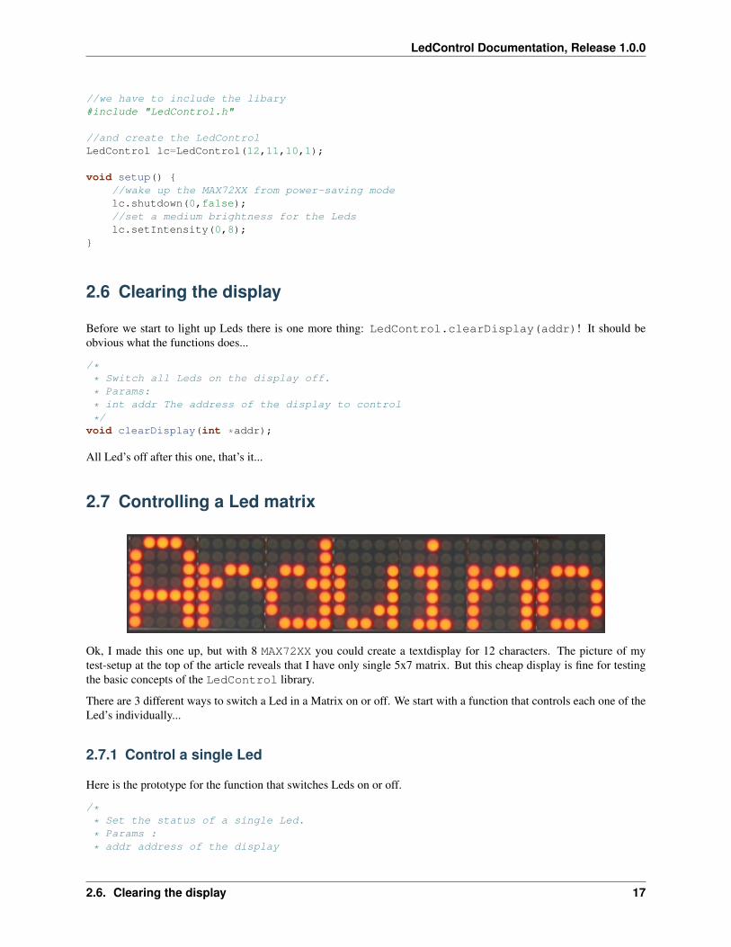
Ok, I made this one up, but with 8 MAX72XX you could create a textdisplay for 12 characters. The picture of mytest-setup at the top of the article reveals that I have only single 5x7 matrix. But this cheap display is fine for testingthe basic concepts of the LedControl library.
There are 3 different ways to switch a Led in a Matrix on or off. We start with a function that controls each one of theLed’s individually...
2.7.1 Control a single Led
Here is the prototype for the function that switches Leds on or off.
/** Set the status of a single Led.
* Params :
* addr address of the display
2.6. Clearing the display 17

LedControl Documentation, Release 1.0.0
* row the row of the Led (0..7)
* col the column of the Led (0..7)
* state If true the led is switched on,
* if false it is switched off
*/void setLed(int addr, int row, int col, boolean state);
The addr and the state arguments should be clear, but what excatly is a row and what is a column on the matrix?It really depends on the wiring bewteen the MAX72XX and your matrix. The LedControl-library assumes the setupused in this schematic:
There are 8 rows (indexed from 0..7) and 8 columns (also indexed from 0..7) in the matrix. If we want to light up theLed which is located at the very right of the 3’rd row from the top, simply take the index of the Led (2.7) and use is asthe row and column arguments.
Here’s some code that lights up a few Leds
18 Chapter 2. The Software library

LedControl Documentation, Release 1.0.0
//switch on the led in the 3’rd row 8’th column//and remember that indices start at 0!lc.setLed(0,2,7,true);//Led at row 0 second from left toolc.setLed(0,0,1,true);delay(500);//switch the first Led off (second one stays on)lc.setLed(0,2,7,false);
setLed() is fine if you light up only a few Leds, but if more Leds need to be updated, it would require many linesof code. So there are two more functions in the library, that control a complete row and column with a single call.
2.7.2 Control a row
The setRow(addr,row,value)-function takes 3 arguments. The first one is the already familiar address of ourdevice. The second one is the row that is going to be updated and the third one the value for this row.
But how do we know which Leds light up for a specific value? The value, a byte, uses a simple encoding where eachbit set to 1 represents a lit led and an unset bit a Led switched off. Here is an example:
We want to light up the marked Leds from the schematic...
The index for the row to be updated is 2. Now we have to set the byte-value for the Leds to be lit. The easiest approachis to include the standard header-file <binary.h> to your sketch. Now you can write down the value in binaryencoding and have an exact mapping between bits set to 1 and the Leds to be switched on. To light up the the Ledsfrom the example we could simply write:
//include this file so we can write down a byte in binary encoding#include <binary.h>
//now setting the leds from the third row on the first device is easylc.setRow(0,2,B10110000);
If for any reason you can not specify the value in binary encoding, here is a simple table that maps the decimal valuesof each bit to the Led it affects. The two rows at bottom give an example for how to calculate the decimal value forthe example from above.
2.7. Controlling a Led matrix 19
LedControl Documentation, Release 1.0.0
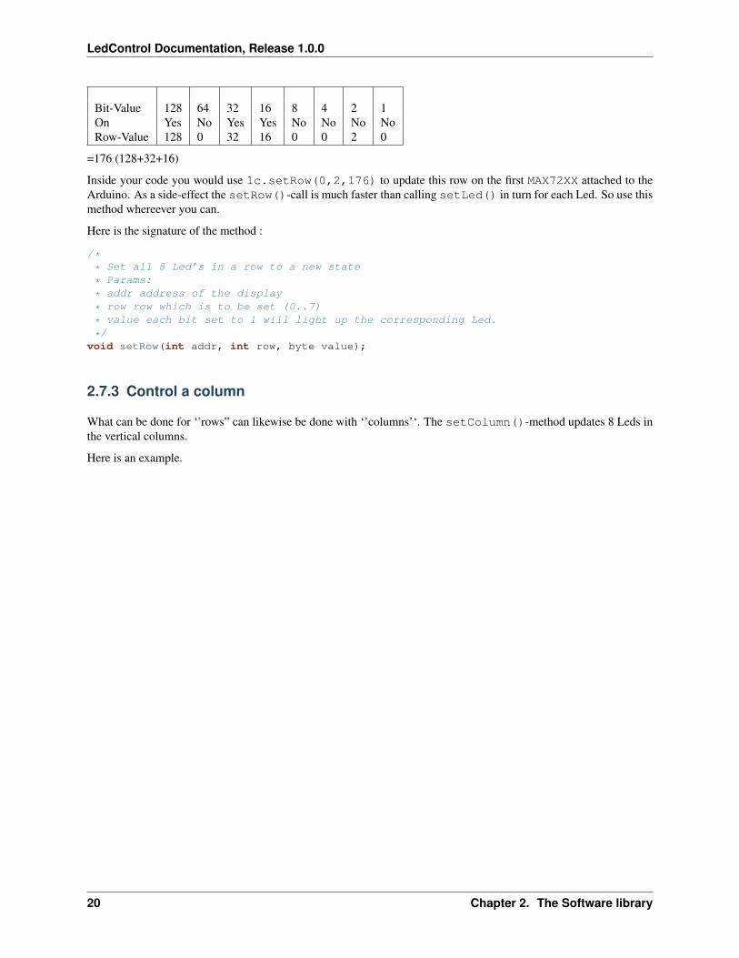
Bit-Value 128 64 32 16 8 4 2 1On Yes No Yes Yes No No No NoRow-Value 128 0 32 16 0 0 2 0
=176 (128+32+16)
Inside your code you would use lc.setRow(0,2,176) to update this row on the first MAX72XX attached to theArduino. As a side-effect the setRow()-call is much faster than calling setLed() in turn for each Led. So use thismethod whereever you can.
Here is the signature of the method :
/** Set all 8 Led’s in a row to a new state
* Params:
* addr address of the display
* row row which is to be set (0..7)
* value each bit set to 1 will light up the corresponding Led.
*/void setRow(int addr, int row, byte value);
2.7.3 Control a column
What can be done for ‘’rows” can likewise be done with ‘’columns’‘. The setColumn()-method updates 8 Leds inthe vertical columns.
Here is an example.
20 Chapter 2. The Software library
LedControl Documentation, Release 1.0.0
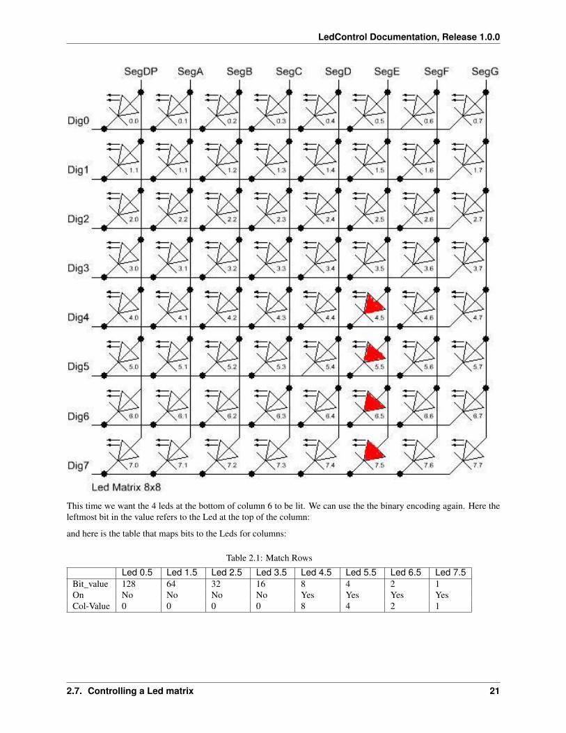
This time we want the 4 leds at the bottom of column 6 to be lit. We can use the the binary encoding again. Here theleftmost bit in the value refers to the Led at the top of the column:
and here is the table that maps bits to the Leds for columns:
Table 2.1: Match Rows
Led 0.5 Led 1.5 Led 2.5 Led 3.5 Led 4.5 Led 5.5 Led 6.5 Led 7.5Bit_value 128 64 32 16 8 4 2 1On No No No No Yes Yes Yes YesCol-Value 0 0 0 0 8 4 2 1
2.7. Controlling a Led matrix 21
LedControl Documentation, Release 1.0.0
Table 2.2: Match Rows
header“”
Led 0.5 Led 1.5 Led 2.5 Led 3.5 Led 4.5 Led 5.5 Led 6.5 Led 7.5
Bit-Value 128 64 32 16 8 4 2 1On No No No No Yes Yes Yes YesCol-Value 0 0 0 0 8 4 2 1
=15 (8+4+2+1)
The signature of the method is almost the same a the row-version of it:
/** Set all 8 Led’s in a column to a new state
* Params:
* addr address of the display
* col column which is to be set (0..7)
* value each bit set to 1 will light up the corresponding Led.
*/ void setColumn(int addr, int col, byte value);
A complete example for the Led matrix functions can be found on the demo-page for the library.
Note: A note on performance...There is an important difference between the way the setRow()- and the setColumn()- methods update theLeds:
• setRow() only needs to send a single int-value to the MAX72XX in order to update all 8 Leds in a row.
• setColumn() uses the setLed()-method internally to update the Leds. The library has to send 8 intsto the driver, so there is a performance penalty when using setColumn(). You won’t notice that visuallywhen using only 1 or 2 cascaded Led-boards, but if you have a long queue of devices (6..8) which all have to beupdated at the same time, that could lead to some delay that is actually visible.
2.8 Control 7-Segment displays
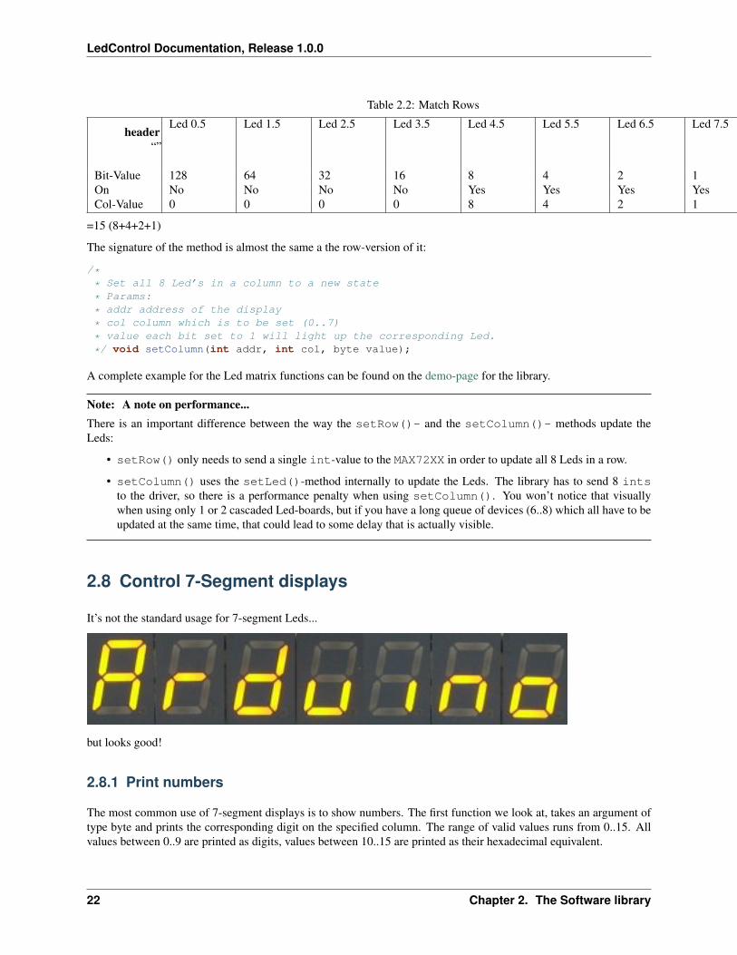
It’s not the standard usage for 7-segment Leds...
but looks good!
2.8.1 Print numbers
The most common use of 7-segment displays is to show numbers. The first function we look at, takes an argument oftype byte and prints the corresponding digit on the specified column. The range of valid values runs from 0..15. Allvalues between 0..9 are printed as digits, values between 10..15 are printed as their hexadecimal equivalent.
22 Chapter 2. The Software library
LedControl Documentation, Release 1.0.0
Any other value will simply be ignored, which means ‘’‘nothing’‘’ will be printed. The column on nthe display willnot be blanked, it will simply retain its last valid value. The decimal point on the column can be switched on or offwith an extra argument.
Here is a small example that prints an int value (-999..999) on a display with 4 digits.
void printNumber(int v) int ones;int tens;int hundreds;boolean negative;
if(v < -999 || v > 999)return;
if(v<0) negative=true;v=v*-1;
ones=v%10;v=v/10;tens=v%10;v=v/10;hundreds=v;if(negative)
//print character ’-’ in the leftmost columnlc.setChar(0,3,’-’,false);
else //print a blank in the sign columnlc.setChar(0,3,’ ’,false);
//Now print the number digit by digitlc.setDigit(0,2,(byte)hundreds,false);lc.setDigit(0,1,(byte)tens,false);lc.setDigit(0,0,(byte)ones,false);
This is the prototype for the function:
/** Display a (hexadecimal) digit on a 7-Segment Display
* Params:
* addr address of the display
* digit the position of the digit on the display (0..7)
* value the value to be displayed. (0x00..0x0F)
* dp sets the decimal point.
*/void setDigit(int addr, int *digit, byte value, *boolean dp);
The digit-argument must be from the range 0..7 because the MAX72XX can drive up to eight 7-segment displays.The index starts at 0 as usual.
2.8.2 Print characters
There is a limited set of characters that make (visual) sense on a 7-segment display. A common use would be thecharacter ‘-‘ for negative values and the 6 characters from ‘A’..’F’ for hex-values.
The setChar(addr,digit,value.dp)-function accepts a value of type char for the whole range of 7-bit ASCIIencoding. Since the recognizable patterns are limited, most of the defined characters will be the <SPACE>-char. Butthere are quite a few characters that make sense on a 7-segment display.
2.8. Control 7-Segment displays 23

LedControl Documentation, Release 1.0.0
Here is the set of printable characters:
• 0 1 2 3 4 5 6 7 8 9
• A a (prints upper case)
• B b (prints lower case)
• C c (prints lower case)
• D d (prints lower case)
• E e (prints upper case)
• F f (prints upper case)
• H h (prints upper case)
• L l (prints upper case)
• P p (prints upper case)
• - (the minus sign)
• ., (lights up the decimal-point)
• _ (the underscore)
• <SPACE> (the blank or space char)
For your conveniance, the hexadecimal characters have also been redefined at the character values 0x00...0x0F. If youwant to mix digits and characters on the display, you can simply take the same byte argument that you would haveused for the setDigit()-function and it will print the hexadecimal value.
The prototype of the function is almost the same as the one for displaying digits.
/** Display a character on a 7-Segment display.
* There are only a few characters that make sense here :
* ’0’,’1’,’2’,’3’,’4’,’5’,’6’,’7’,’8’,’9’,’0’,
* ’A’,’b’,’c’,’d’,’E’,’F’,’H’,’L’,’P’,
* ’.’,’-’,’_’,’ ’
* Params:
* addr address of the display
* digit the position of the character on the display (0..7)
* value the character to be displayed.
* dp sets the decimal point.
*/void setChar(int addr, int digit, char value, *boolean dp);i
2.9 Commented demos for the library
Some commented demos for the LedControl-library are on page [[LedControlDemos]]. You can also downloadthe code for the demos from [[LedControlDemos | there]].
2.10 Sourcecode and download
The sourcecode of the library is available as a zip-file : LedControl.zip
The zip-file will create a new directory named LedControl with 3 files:
24 Chapter 2. The Software library
LedControl Documentation, Release 1.0.0
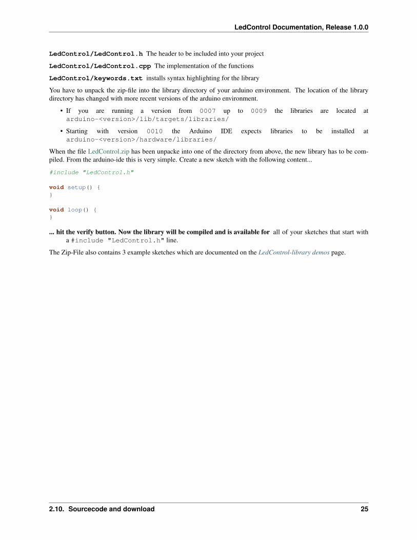
LedControl/LedControl.h The header to be included into your project
LedControl/LedControl.cpp The implementation of the functions
LedControl/keywords.txt installs syntax highlighting for the library
You have to unpack the zip-file into the library directory of your arduino environment. The location of the librarydirectory has changed with more recent versions of the arduino environment.
• If you are running a version from 0007 up to 0009 the libraries are located atarduino-<version>/lib/targets/libraries/
• Starting with version 0010 the Arduino IDE expects libraries to be installed atarduino-<version>/hardware/libraries/
When the file LedControl.zip has been unpacke into one of the directory from above, the new library has to be com-piled. From the arduino-ide this is very simple. Create a new sketch with the following content...
#include "LedControl.h"
void setup()
void loop()
... hit the verify button. Now the library will be compiled and is available for all of your sketches that start witha #include "LedControl.h" line.
The Zip-File also contains 3 example sketches which are documented on the LedControl-library demos page.
2.10. Sourcecode and download 25

LedControl Documentation, Release 1.0.0
26 Chapter 2. The Software library

CHAPTER 3
LedControl-library demos
Here are a few demo-sketches that using the LedControl-library. You can either copy+paste the code directly into theeditor of the Arduino-IDE, or download the sketches in a zip-file :
LedControlDemos.zip
Note: LedControl must be installed first...The LedControl-library must obviously be installed on your computer, otherwise the demos won’t even compile...
3.1 Led matrix
Here is a small demo to be run on a Led matrix. A matrix of at least 5x7 Leds is recommended, but there is no problemrunning it on a smaller matrix, it simply won’t look that good.
Please have a close look at the initialization-code and the setup()-function. If you don’t to pull the MAX72XX frompowersaving mode with the shutdown()-function or if you forget to call setIntensiy() for setting the displaybrightness, your Leds my remain dark even though the sketch runs without errors.
Otherwise the code should be straight forward. rows(), columns() and ‘‘ single()‘‘ show the different ways toupdate the matrix. writeArduinoOnMatrix() is a bit of eye-candy, that shows how you could drive a small textdisplay if you had a few spare MAX72XX.
Note: Update Pin numbers...Please update the pin-numbers used in the code according to you hardware!
//We always have to include the library #include "LedControl.h"
/* Now we need a LedControl to work with.
* These pin numbers will probably not work with your hardware
* pin 12 is connected to the DataIn
* pin 11 is connected to the CLK
* pin 10 is connected to LOAD
* We have only a single MAX72XX.
*/LedControl lc=LedControl(12,11,10,1);
/* we always wait a bit between updates of the display */unsigned long delaytime=100;
27
LedControl Documentation, Release 1.0.0
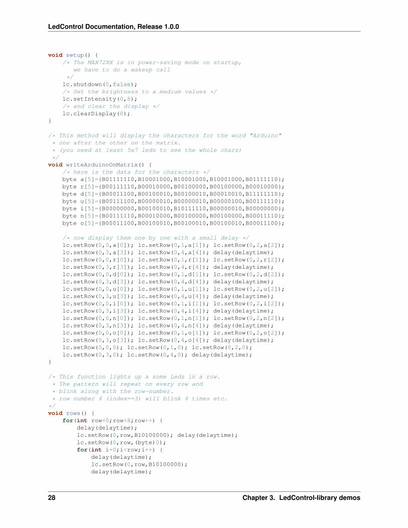
void setup() /* The MAX72XX is in power-saving mode on startup,
we have to do a wakeup call
*/lc.shutdown(0,false);/* Set the brightness to a medium values */lc.setIntensity(0,8);/* and clear the display */lc.clearDisplay(0);
/* This method will display the characters for the word "Arduino"
* one after the other on the matrix.
* (you need at least 5x7 leds to see the whole chars)
*/void writeArduinoOnMatrix()
/* here is the data for the characters */byte a[5]=B01111110,B10001000,B10001000,B10001000,B01111110;byte r[5]=B00111110,B00010000,B00100000,B00100000,B00010000;byte d[5]=B00011100,B00100010,B00100010,B00010010,B11111110;byte u[5]=B00111100,B00000010,B00000010,B00000100,B00111110;byte i[5]=B00000000,B00100010,B10111110,B00000010,B00000000;byte n[5]=B00111110,B00010000,B00100000,B00100000,B00011110;byte o[5]=B00011100,B00100010,B00100010,B00100010,B00011100;
/* now display them one by one with a small delay */lc.setRow(0,0,a[0]); lc.setRow(0,1,a[1]); lc.setRow(0,2,a[2]);lc.setRow(0,3,a[3]); lc.setRow(0,4,a[4]); delay(delaytime);lc.setRow(0,0,r[0]); lc.setRow(0,1,r[1]); lc.setRow(0,2,r[2]);lc.setRow(0,3,r[3]); lc.setRow(0,4,r[4]); delay(delaytime);lc.setRow(0,0,d[0]); lc.setRow(0,1,d[1]); lc.setRow(0,2,d[2]);lc.setRow(0,3,d[3]); lc.setRow(0,4,d[4]); delay(delaytime);lc.setRow(0,0,u[0]); lc.setRow(0,1,u[1]); lc.setRow(0,2,u[2]);lc.setRow(0,3,u[3]); lc.setRow(0,4,u[4]); delay(delaytime);lc.setRow(0,0,i[0]); lc.setRow(0,1,i[1]); lc.setRow(0,2,i[2]);lc.setRow(0,3,i[3]); lc.setRow(0,4,i[4]); delay(delaytime);lc.setRow(0,0,n[0]); lc.setRow(0,1,n[1]); lc.setRow(0,2,n[2]);lc.setRow(0,3,n[3]); lc.setRow(0,4,n[4]); delay(delaytime);lc.setRow(0,0,o[0]); lc.setRow(0,1,o[1]); lc.setRow(0,2,o[2]);lc.setRow(0,3,o[3]); lc.setRow(0,4,o[4]); delay(delaytime);lc.setRow(0,0,0); lc.setRow(0,1,0); lc.setRow(0,2,0);lc.setRow(0,3,0); lc.setRow(0,4,0); delay(delaytime);
/* This function lights up a some Leds in a row.
* The pattern will repeat on every row and
* blink along with the row-number.
* row number 4 (index==3) will blink 4 times etc.
*/void rows()
for(int row=0;row<8;row++) delay(delaytime);lc.setRow(0,row,B10100000); delay(delaytime);lc.setRow(0,row,(byte)0);for(int i=0;i<row;i++)
delay(delaytime);lc.setRow(0,row,B10100000);delay(delaytime);
28 Chapter 3. LedControl-library demos

LedControl Documentation, Release 1.0.0
lc.setRow(0,row,(byte)0);
/* This function lights up a some Leds in a column.
* The pattern repeats on every column and will blink along
* with the column-number.
* column number 4 (index==3) will blink 4 times etc.
*/void columns()
for(int col=0;col<8;col++) delay(delaytime);lc.setColumn(0,col,B10100000);delay(delaytime);lc.setColumn(0,col,(byte)0);for(int i=0;i<col;i++)
delay(delaytime);lc.setColumn(0,col,B10100000);delay(delaytime);lc.setColumn(0,col,(byte)0);
/* This function will light up every Led on the matrix.
* The led will blink along with the row-number.
* row number 4 (index==3) will blink 4 times etc. */void single()
for(int row=0;row<8;row++) for(int col=0;col<8;col++)
delay(delaytime);lc.setLed(0,row,col,true);delay(delaytime);for(int i=0;i<col;i++)
lc.setLed(0,row,col,false);delay(delaytime);lc.setLed(0,row,col,true);delay(delaytime);
void loop() writeArduinoOnMatrix();rows();columns();single();
3.2 7-segment display
Here is a demo to be run on a 7-segment display. The initialization of the devices is exactly the same as in the matrixdemo. scrollDigits() uses the setDigits() method for (hex-)numbers between 0 and 15.
3.2. 7-segment display 29

LedControl Documentation, Release 1.0.0
writeArduinoOn7Segment() is a little bit more interesting, as it uses the setChar()-method for the prede-fined characters ‘’ ‘A’,’d’ ‘’ and the setRow()-function for creating a mock up of the missing characters.
Note: Update Pin numbers...Please update the pin-numbers used in the code according to you hardware!
//We always have to include the library #include "LedControl.h"
/* Now we need a LedControl to work with.
* These pin numbers will probably not work with your hardware
* pin 12 is connected to the DataIn
* pin 11 is connected to the CLK
* pin 10 is connected to LOAD
* We have only a single MAX72XX.
*/LedControl lc=LedControl(12,11,10,1);
/* we always wait a bit between updates of the display */unsigned long delaytime=250;
void setup() /* The MAX72XX is in power-saving mode on startup,
* we have to do a wakeup call
*/lc.shutdown(0,false);/* Set the brightness to a medium values */lc.setIntensity(0,8);/* and clear the display */lc.clearDisplay(0);
/* This method will scroll the characters for the word "Arduino"
* one digit 0. */void writeArduinoOn7Segment()
lc.setChar(0,0,’a’,false);delay(delaytime);lc.setRow(0,0,0x05);delay(delaytime);lc.setChar(0,0,’d’,false);delay(delaytime);lc.setRow(0,0,0x1c);delay(delaytime);lc.setRow(0,0,B00010000);delay(delaytime);lc.setRow(0,0,0x15);delay(delaytime);lc.setRow(0,0,0x1D);delay(delaytime);lc.clearDisplay(0);delay(delaytime);
/* This method will scroll all the hexa-decimal numbers and
* letters on the display. You will need at least four 7-Segment
* digits. otherwise it won’t really look that good.
*/
30 Chapter 3. LedControl-library demos

LedControl Documentation, Release 1.0.0
void scrollDigits() for(int i=0;i<13;i++)
lc.setDigit(0,3,i,false);lc.setDigit(0,2,i+1,false);lc.setDigit(0,1,i+2,false);lc.setDigit(0,0,i+3,false);delay(delaytime);
lc.clearDisplay(0);delay(delaytime);
void loop() writeArduinoOn7Segment();scrollDigits();
3.3 Cascaded devices
Here is a demo that shows how to address more than one MAX72XX from a single LedControl variable. You wouldobviously need at least two cascaded devices to test this. The demo doesn’t do anything exciting. It simply uses a bigloop in which it switches all Leds on all devices on and off, one after the other.
The thing to remember is that you have to initialize all of the devices, like we do it in the setup()-function whereall of the MAX72XX are initialized in a loop.
Note: Update Pin numbers...Please update the pin-numbers used in the code according to you hardware!
//We always have to include the library#include "LedControl.h"
/* Now we need a LedControl to work with.
* These pin numbers will probably not work with your hardware
* pin 12 is connected to the DataIn
* pin 11 is connected to the CLK
* pin 10 is connected to LOAD
* Please set the number of devices you have
* But the maximum default of 8 MAX72XX will also work.
*/LedControl lc=LedControl(12,11,10,8);
/* we always wait a bit between updates of the display */unsigned long delaytime=500;
/* This time we have more than one device.
* But all of them have to be initialized individually.
*/void setup()
//we have already set the number of devices//when we created the LedControlint devices=lc.getDeviceCount();//we have to init all devices in a loopfor(int address=0;address<devices;address++)
/* The MAX72XX is in power-saving mode on startup*/
3.3. Cascaded devices 31

LedControl Documentation, Release 1.0.0
lc.shutdown(address,false);/* Set the brightness to a medium value */lc.setIntensity(address,8);/* and clear the display */lc.clearDisplay(address);
void loop() //read the number cascaded devices intdevices=lc.getDeviceCount();
//we have to init all devices in a loopfor(int row=0;row<8;row++)
for(int col=0;col<8;col++) for(int address=0;address<devices;address++)
delay(delaytime);lc.setLed(address,row,col,true);delay(delaytime);lc.setLed(address,row,col,false);
32 Chapter 3. LedControl-library demos

CHAPTER 4
Known bugs
Currently none (with Arduino 0022 and Arduino 1.0 (RC1))
33

LedControl Documentation, Release 1.0.0
34 Chapter 4. Known bugs
CHAPTER 5
Revision History
February 27, 2013 Moved code to Github and documentation to Read The Docs
September 10, 2012 Changed the software license from LGPL to an MIT-style license.
September 19, 2011 Uploaded new version of LedControl.zip. Release 1.0 of the Arduino-IDE renamed the internalheader file WProgramm.h to Arduino.h. The include statement in LedControl.h was updated so thelibrary compiles under pre- and post-1.0 version of the IDE
October 14, 2008 Uploaded a new version of the LedControl.zip. The original version did not compile under arduino-0012.
December 5, 2007 Documentation and sourcecode is now hosted on the arduino playground
June 23, 2007 First public release
35
LedControl Documentation, Release 1.0.0
36 Chapter 5. Revision History

CHAPTER 6
Feedback
Your first stop should be the arduino forum section Hardware/Interfacing which I visit regulary. But you arealso welcome to send questions, objections or corrections to <[email protected]>
37

LedControl Documentation, Release 1.0.0
38 Chapter 6. Feedback

CHAPTER 7
License (The software)
The sourcecode for this library is released under the Terms of the GNU Lesser General Public License version 2.1.
39