lecture9 &10_tdm
TRANSCRIPT

8/7/2019 Lecture9 &10_TDM
http://slidepdf.com/reader/full/lecture9-10tdm 1/45
Time Division Multiplexing
Data Communication and
Networks
Prof. Dr. Abdul Qadeer Khan Rajput
By

8/7/2019 Lecture9 &10_TDM
http://slidepdf.com/reader/full/lecture9-10tdm 2/45
2

8/7/2019 Lecture9 &10_TDM
http://slidepdf.com/reader/full/lecture9-10tdm 3/45
3
8/7/2019 Lecture9 &10_TDM
http://slidepdf.com/reader/full/lecture9-10tdm 4/45
4

8/7/2019 Lecture9 &10_TDM
http://slidepdf.com/reader/full/lecture9-10tdm 5/45
5

8/7/2019 Lecture9 &10_TDM
http://slidepdf.com/reader/full/lecture9-10tdm 6/45
6

8/7/2019 Lecture9 &10_TDM
http://slidepdf.com/reader/full/lecture9-10tdm 7/45
7

8/7/2019 Lecture9 &10_TDM
http://slidepdf.com/reader/full/lecture9-10tdm 8/45
8

8/7/2019 Lecture9 &10_TDM
http://slidepdf.com/reader/full/lecture9-10tdm 9/45
9

8/7/2019 Lecture9 &10_TDM
http://slidepdf.com/reader/full/lecture9-10tdm 10/45
10
8/7/2019 Lecture9 &10_TDM
http://slidepdf.com/reader/full/lecture9-10tdm 11/45
11
8/7/2019 Lecture9 &10_TDM
http://slidepdf.com/reader/full/lecture9-10tdm 12/45
12

8/7/2019 Lecture9 &10_TDM
http://slidepdf.com/reader/full/lecture9-10tdm 13/45
13
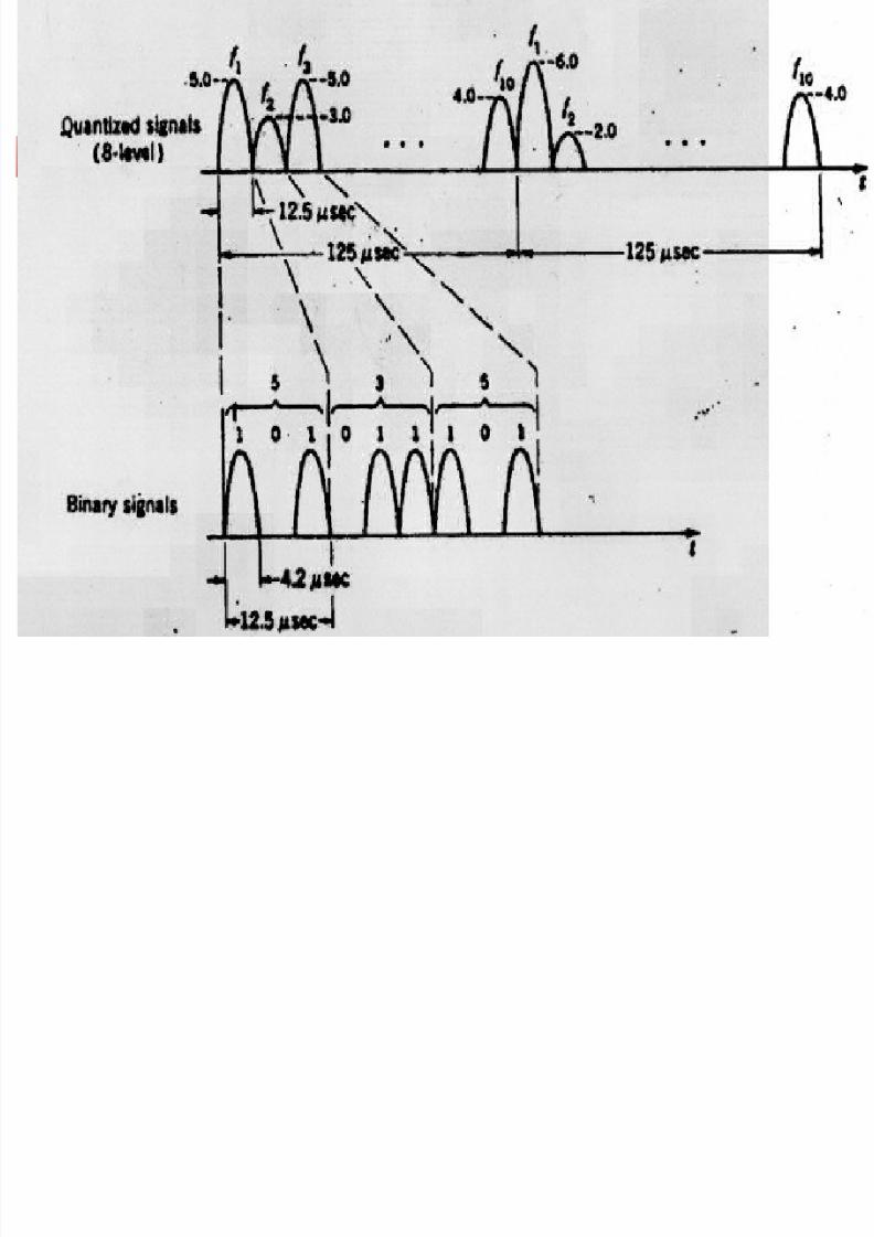
In the previous figure , the sampled amplitude of 5.3 is

8/7/2019 Lecture9 &10_TDM
http://slidepdf.com/reader/full/lecture9-10tdm 14/45
14
TDM

8/7/2019 Lecture9 &10_TDM
http://slidepdf.com/reader/full/lecture9-10tdm 15/45
15
,and f10 (t) represent 10 different voice channels. At the

8/7/2019 Lecture9 &10_TDM
http://slidepdf.com/reader/full/lecture9-10tdm 16/45
16

8/7/2019 Lecture9 &10_TDM
http://slidepdf.com/reader/full/lecture9-10tdm 17/45
17

8/7/2019 Lecture9 &10_TDM
http://slidepdf.com/reader/full/lecture9-10tdm 18/45
18
TDM Definition
Time Division Multiplex (TDM) is theprocess of combining signals together
in the time domain.

8/7/2019 Lecture9 &10_TDM
http://slidepdf.com/reader/full/lecture9-10tdm 19/45
19
TDM Basics
The basic principle of TDM is SamplingTheorem.
The basic unit inTDM is Time Slot.
The data in TDM isgrouped into Frames,which consists of onecycle of time slots.
T
3T

8/7/2019 Lecture9 &10_TDM
http://slidepdf.com/reader/full/lecture9-10tdm 20/45
20
TDM
TDM is a digitalmultiplexingtechnique to combinedata
Instead of sharing aportion of thebandwidth as in FDM,time is shared.
Each connectionoccupies a portion of time in the link.
In a TDM, the datarate of the link is ntimes faster, and theunit duration is ntimes shorter

8/7/2019 Lecture9 &10_TDM
http://slidepdf.com/reader/full/lecture9-10tdm 21/45
21
Interleaving
Interleaving is the process of multiplexing.
In TDM, synchronization between the sender and receiver isvery important.

8/7/2019 Lecture9 &10_TDM
http://slidepdf.com/reader/full/lecture9-10tdm 22/45
22
Interleaving
TDM can be visualizedas two fast rotatingswitches, one on themultiplexing side andthe other on the de-
multiplexing side. Theswitches aresynchronized androtate at the samespeed, but in oppositedirections. On themultiplexing side, asthe switch opens infront of a connection,that connection hasthe opportunity tosend a unit onto thepath. This process iscalled interleaving.

8/7/2019 Lecture9 &10_TDM
http://slidepdf.com/reader/full/lecture9-10tdm 23/45
23
Four channels are multiplexed using TDM. If each channel
sends 100 bytes/s and we multiplex 1 byte per channel, show
the frame traveling on the link, the size of the frame, the
duration of a frame, the frame rate, and the bit rate for the link.
SolutionSolution
The multiplexer is shown in Figure.
Example 6

8/7/2019 Lecture9 &10_TDM
http://slidepdf.com/reader/full/lecture9-10tdm 24/45
24
T-1 line for multiplexingtelephone lines
T lines are digitallines designed for thetransmission of digitaldata, audio, or video.
T lines also can beused for analogtransmission (regulartelephoneconnections),provided the analog
signals are sampledfirst, then time-division multiplexed.

8/7/2019 Lecture9 &10_TDM
http://slidepdf.com/reader/full/lecture9-10tdm 25/45
25
A multiplexer combines four 100-Kbps channels using a time slot
of 2 bits. Show the output with four arbitrary inputs. What is the
frame rate? What is the frame duration? What is the bit rate? What
is the bit duration?
SolutionSolution
Figure shows the output for four arbitrary inputs.
Example 7

8/7/2019 Lecture9 &10_TDM
http://slidepdf.com/reader/full/lecture9-10tdm 26/45
26
Framing bits
For synchronization betweenmultiplexer and demultiplexer,one or more synchronization
bits are usually added to thebeginning of each frame. Thesebits, called framing bits, followa pattern, frame to frame, thatallows the demultiplexer tosynchronize with the incoming
stream so that it can separatethe time slots accurately.In bit padding, the multiplexeradds extra bits to a device’ssource stream to force thespeed relationships among the
various devices into integermultiples of each other.
8/7/2019 Lecture9 &10_TDM
http://slidepdf.com/reader/full/lecture9-10tdm 27/45
27
We have four sources, each creating 250 characters per
second. If the interleaved unit is a character and 1
synchronizing bit is added to each frame, find (1) the data
rate of each source, (2) the duration of each character in
each source, (3) the frame rate, (4) the duration of eachframe, (5) the number of bits in each frame, and (6) the
data rate of the link.
Example 8

8/7/2019 Lecture9 &10_TDM
http://slidepdf.com/reader/full/lecture9-10tdm 28/45
28
We can answer the questions as follows:
1. The data rate of each source is 2000 bps = 2 Kbps.2. The duration of a character is 1/250 s, or 4 ms.
3. The link needs to send 250 frames per second.
4. The duration of each frame is 1/250 s, or 4 ms.
5. Each frame is 4 x 8 + 1 = 33 bits.
6. The data rate of the link is 250 x 33, or 8250 bps.
SolutionSolution
8/7/2019 Lecture9 &10_TDM
http://slidepdf.com/reader/full/lecture9-10tdm 29/45
29
Two channels, one with a bit rate of 100 Kbps and another
with a bit rate of 200 Kbps, are to be multiplexed. How this
can be achieved? What is the frame rate? What is the frame
duration? What is the bit rate of the link?
SolutionSolution
We can allocate one slot to the first channel and two slots
to the second channel. Each frame carries 3 bits. The
frame rate is 100,000 frames per second because it
carries 1 bit from the first channel. The frame duration is
1/100,000 s, or 10 ms. The bit rate is 100,000 frames/s x
3 bits/frame, or 300 Kbps.
Example 9

8/7/2019 Lecture9 &10_TDM
http://slidepdf.com/reader/full/lecture9-10tdm 30/45
30
hierarchy
DS-0 service is a singledigital channel of 64Kbps.
DS-1 is a 1.544-Mbps
service [24 times 64Kbps plus 8Kbps of overhead]
And so on. DS-0, DS-1, and so on are
the names of services. To
implement thoseservices, the telephonecompanies use T lines (T-1 to T-4).

8/7/2019 Lecture9 &10_TDM
http://slidepdf.com/reader/full/lecture9-10tdm 31/45
31
Table DS and T lines ratesTable DS and T lines rates
Service Line Rate
(Mbps)
Voice Channels
DS-1DS-1 T-1T-1 1.5441.544 2424
DS-2DS-2 T-2T-2 6.3126.312 9696
DS-3DS-3 T-3T-3 44.73644.736 672672
DS-4DS-4 T-4T-4 274.176274.176 40324032

8/7/2019 Lecture9 &10_TDM
http://slidepdf.com/reader/full/lecture9-10tdm 32/45
32
Table .Table .
E lineE line
ratesrates
E Line Rate(Mbps)
VoiceChannels
E-1E-1 2.0482.048 3030
E-2E-2 8.4488.448 120120
E-3E-3 34.36834.368 480480
E-4E-4 139.264139.264 19201920
Europeans use a version of T lines called E lines
The two systems are conceptually identical, but their capacities differ.

8/7/2019 Lecture9 &10_TDM
http://slidepdf.com/reader/full/lecture9-10tdm 33/45
33
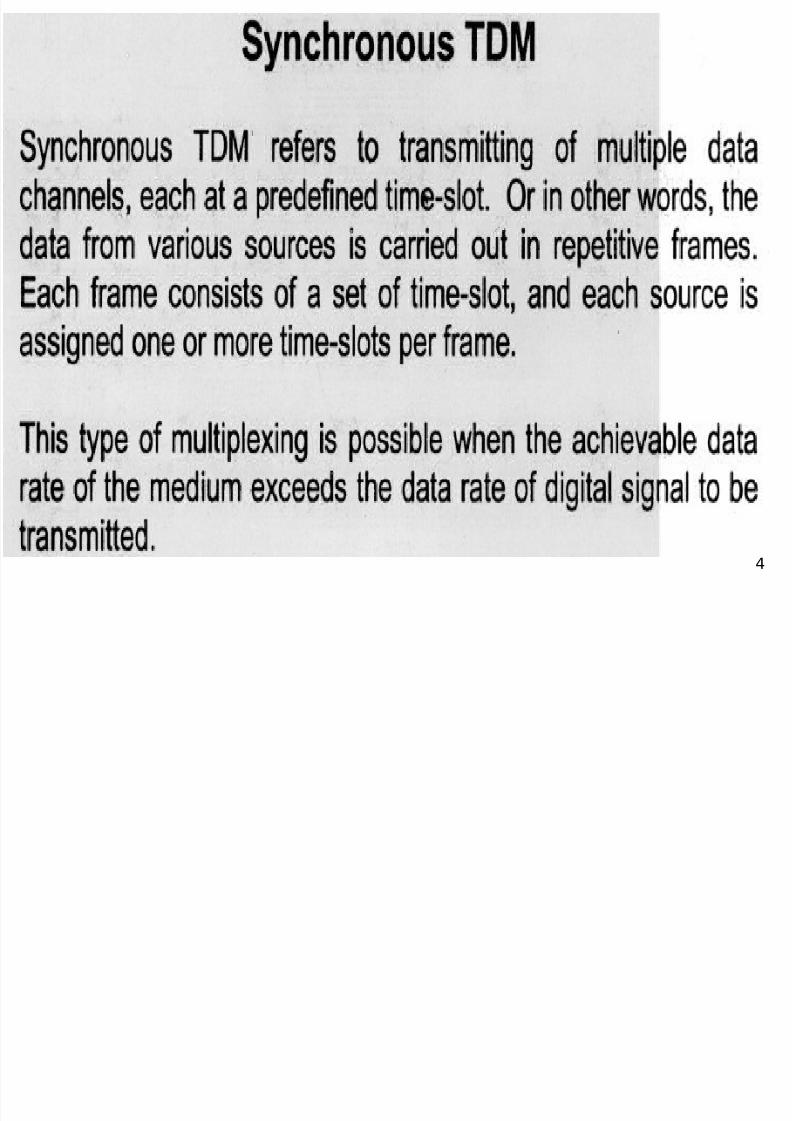
Synchronous TDM
In synchronous TDM, each source is pre-assigned a fixed location of time slot.
Each source can and only can send informationat the time slot given to it. If a source has nodata to send, its time slot remains empty. Thiscan lead to inefficiency.
If n sources are grouped together, the total datarate of the path is n times the original data rate
of each source.
Synchronous TDM

8/7/2019 Lecture9 &10_TDM
http://slidepdf.com/reader/full/lecture9-10tdm 34/45
34
Synchronous TDMExample
S h TDM

8/7/2019 Lecture9 &10_TDM
http://slidepdf.com/reader/full/lecture9-10tdm 35/45
35
Synchronous TDM -Multiplexing
S h TDM

8/7/2019 Lecture9 &10_TDM
http://slidepdf.com/reader/full/lecture9-10tdm 36/45
36
Synchronous TDM -Demultiplexing

8/7/2019 Lecture9 &10_TDM
http://slidepdf.com/reader/full/lecture9-10tdm 37/45
37
We have four sources, each creating 250 characters per
second. If the interleaved unit is a character and 1
synchronizing bit is added to each frame, find (1) the datarate of each source, (2) the duration of each character in
each source, (3) the frame rate, (4) the duration of each
frame, (5) the number of bits in each frame, and (6) the
data rate of the link.
TDM Example

8/7/2019 Lecture9 &10_TDM
http://slidepdf.com/reader/full/lecture9-10tdm 38/45
38
We can answer the questions as follows:
1. The data rate of each source is (250 chars x 8 bits) =
2000 bps = 2 kbps.
2. The duration of a character is 1/250 s, or 4 ms.3. The link needs to send 250 frames per second.
4. The duration of each frame is 1/250 s, or 4 ms.
5. Each frame is (4sources x 8bits) + 1sync = 33 bits.
6. The data rate of the link is 250 x 33, or 8250 bps.(strictly, ‘bit rate’ of the link is 8250bps – the actual
data rate is only 8000 data bits/s)
SolutionSolution

8/7/2019 Lecture9 &10_TDM
http://slidepdf.com/reader/full/lecture9-10tdm 39/45
39
Asynchronous TDM
In asynchronous TDM or statistical TDM,only sources containing data will be sentwith time slot. Therefore, asynchronous
TDM can avoid bandwidth waste insynchronous TDM.
But, in order to distinguish data fromdifferent sources, address should be added
into the frame structure, increasing theoverhead of the transmission.
Asynchronous TDM

8/7/2019 Lecture9 &10_TDM
http://slidepdf.com/reader/full/lecture9-10tdm 40/45
40
Asynchronous TDMExample

8/7/2019 Lecture9 &10_TDM
http://slidepdf.com/reader/full/lecture9-10tdm 41/45
41
Address and Overhead
As shown below, address is added before the datafrom each source.
It is practical only when the data size for each time
slot is relatively larger than the address.
In this example, the addressing
information takes up as much space as
the actual data - inefficient

8/7/2019 Lecture9 &10_TDM
http://slidepdf.com/reader/full/lecture9-10tdm 42/45
42
TDM in Telephone System
FDM was used in the original telephonesystem, but now the telephone lines (exceptthe subscriber line) are all in digital form, soFDM is not in use now.
There are two types of TDM used intelephone system. In US, T-1 line with basicrate of 1.544 Mbps is used, while in Europeand China, E-1 Line of 2.048 Mbps is in use.
DS is a ‘service’, T-n is a ‘line’
Digital Signal (DS)

8/7/2019 Lecture9 &10_TDM
http://slidepdf.com/reader/full/lecture9-10tdm 43/45
43
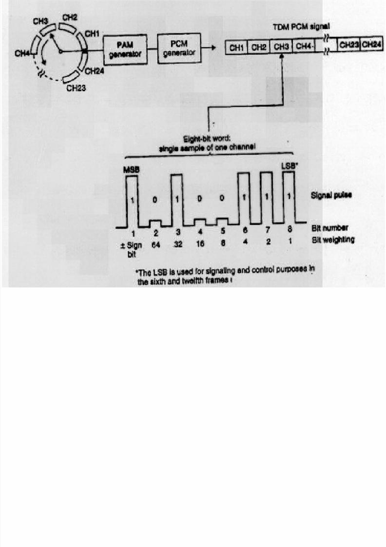
Digital Signal (DS)Hierarchy in US
8k sample/sec x 8bit samplesgives 64kbps basic line
DS1 = 24 x DS0 = 24x64k=1536k
1536k + 8k(sync) =1544k

8/7/2019 Lecture9 &10_TDM
http://slidepdf.com/reader/full/lecture9-10tdm 44/45
44
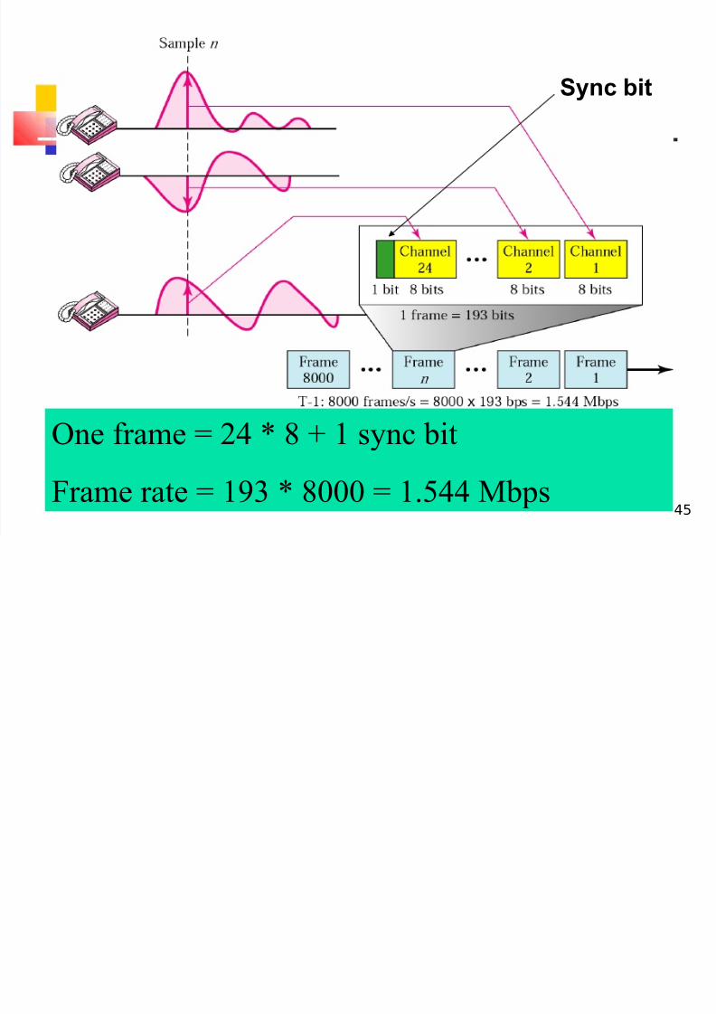
T-1 Frame Structure
Data sync
8/7/2019 Lecture9 &10_TDM
http://slidepdf.com/reader/full/lecture9-10tdm 45/45
One frame = 24 * 8 + 1 sync bit
Sync bit