lecture03 residents gradient echo mri - labs.dgsom.ucla.edu · fase single-shot fse 3d tse with...
TRANSCRIPT

Gradient Echo MRI
Kyung Sung, Ph.D. Assistant Professor of Radiology
Magnetic Resonance Research Labs
Review of Spin Echo MRI

SNR vs Resolution vs Scan Time
High SNR
Sharp Images
Fast Scans
Coils, field strength, pulse sequence
affect starting point!
T1 Contrast
Sig
nal
Time
Sig
nal
Time
Short Repetition Long Repetition
CSF
White/Gray Matter

T2 Contrast
CSF
White/Gray Matter
Sig
nal
Time
Long Echo-TimeShort Echo-Time
0 200 400 600 800 10000
0.2
0.4
0.6
0.8
1
Time [ms]
Tran
sver
se M
agne
tizat
ion
[a.u
.]
White Matter T2
White Matter T2*
T2*<T2 (always!)

0 1000 2000 3000 4000 5000
100
75
50
25
00
Decay Time [ms]
Perc
ent
Sign
al [
a.u.
]
IncreasingContrastDose
T1 Shortening Agents
Increasing dose of a T1 shortening agent increases signal, but too much contrast is unsafe and will compromise image quality.
Spin Echo Contrast
AEcho / ⇢⇣1� e�TR/T1
⌘e�TE/T2
Longer TR minimizes
T1 contrast
Short TE minimizes T2 contrast
Intermediate TR maximizes T1 contrast
Intermediate TE maximizes T2 contrast
TE TR
Spin Density Short Long
T1-Weighted Short IntermediateT2-Weighted Intermediate Long
Spin Echo Parameters

Wasted Time
Spin Echo90°
180°
RF
GSlice
GPhase
GReadout
Signal
TE
90°
TR
Echo-1 Echo-3
Turbo Spin Echo (TSE)90°
180° 180° 180°
Echo-2
RF
GSlice
GPhase
GReadout
Signal

Turbo Spin Echo vs. Spin EchoFast Spin Echo Spin Echo
TR = 2500TE = 116ETL = 16NEX = 224 slices
17 slices/pass2 passes
Time = 2:51
TR = 2500TE = 112ETL = N/ANEX = 124 slices20 slices/pass2 passesTime = 22:21
Images: Courtesy Frank Korosec
Shorter scan time.More T2-weighted.
Fat is brighter.Higher SAR.
MRI Acronyms
Siemens GE Phillips Toshiba Hitachi
Turbo spin echo/Fast spin echo TSE FSE TSE FSE FSE
Single-shot TSE HASTE Single-shot FSE
Single-shot FSE FASE Single-shot
FSE
3D TSE with variable flip angle SPACE CUBE VISTA mVox

Relaxation - True or False?
1. T2* > T2 > T1
2. Long T1s appear bright on a T1-weighted image
3. Short T2s appear dark on a T2-weighted image
Relaxation - True or False?
1. T2* > T2 > T1
2. Long T1s appear bright on a T1-weighted image
3. Short T2s appear dark on a T2-weighted image
Sig
nal
Time
Sig
nal
Time

Relaxation - True or False?
1. T1(CSF) > T1(Gray Matter)
2. T2(Liver) < T2(Fat)
Relaxation - True or False?
1. T1(CSF) > T1(Gray Matter)
2. T2(Liver) < T2(Fat)
Tissue T1 [ms] T2 [ms]gray matter 925 100white matter 790 92
muscle 875 47fat 260 85
kidney 650 58liver 500 43CSF 2400 180

Quiz: Contrast Agents - True or False?
1. Gadolinium-based agents act to lengthen T1.
2. MRI contrast agents are widely considered very safe.
Spin Echoes - True or False?1. The 90-180 pair is the hallmark of the spin echo
sequence.
2. The 180 pulse is an inversion pulse.
3. Spin echoes are ultrafast sequences that provide T1 or T2* weighted images.

Spin Echoes - True or False?1. The 90-180 pair is the hallmark of the spin echo
sequence.
2. The 180 pulse is an inversion pulse.
3. Spin echoes are ultrafast sequences that provide T1 or T2* weighted images.
RF
TE
90° 180° TR
Spin Echoes - True or False?1. Long TE and long TR for T2-weighted.
2. Short TE and short TR for T1-weighted.
3. Spin echoes are low SAR sequences.

Spin Echoes - True or False?1. Long TE and long TR for T2-weighted.
2. Short TE and short TR for T1-weighted.
3. Spin echoes are low SAR sequences.
AEcho / ⇢⇣1� e�TR/T1
⌘e�TE/T2
Longer TR minimizes T1 contrast
Short TE minimizes T2 contrast
Multi-Echo Imaging - True or False?
1. Multi-echo imaging can decrease scan times by 2x or more.
2. Turbo spin echo is excellent for fast T2-weighted imaging.
3. Spin Echo EPI is routine for diffusion weighted imaging.

Fast Imaging - True or False?
1. Long TRs are important for T2 weighted imaging because they eliminate T1-contrast.
2. Slice interleaving is better suited for T2-weighted imaging than T1-weighted.
3. Multi-echo imaging can be combined with multi-slice imaging.
Gradient Echo Imaging

Gradient Echo Sequences
• Spoiled Gradient Echo – SPGR, FLASH, T1-FFE
• Balanced Steady-State Free Precession – TrueFISP, FIESTA, Balanced FFE
Principal GRE Advantages
• Fast Imaging Applications – Why? Can use a shorter TE/TR than spin echo – When? Breath-held, realtime, & 3D volume imaging
• Flexible image contrast – Why? Adjusting TE/TR/FA controls the signal – When? Characterize a tissue for diagnosis
• Bright blood signal – Why? Inflowing spins haven’t “seen” numerous RF pulses – When? Cardiovascular & angiographic applications
• Low SAR – Why? Imaging flip angles are (typically) small – When? When heating risks are a concern

Principal GRE Advantages
• Quantitative – Why? Multi-echo acquisition are practical. – When? Flow quantification & Fat/Water mapping
• Susceptibility Weighted Imaging – Why? No refocusing pulse. – When? T2*-weighted (hemorrhage) imaging
• Reduced Slice Cross-talk – Why? SE hard to match slice profile of 90° & 180° – When? Little or no slice gap for 2D multi-slice
• More...
Principal GRE Disadvantages
• Off-resonance sensitivity – Why? No refocusing pulse
• Field inhomogeneity, Susceptibility, & Chemical shift
• T2*-weighted rather than T2-weighted – Why? No re-focusing pulse
• Spin-spin dephasing is not reversible with GRE
• Larger metal artifacts than SE – Why? No refocusing pulse.
• Large field inhomogeneities aren’t corrected with GRE

RF
Slice Select
Phase Encode
Freq. Encode
Free Induction Decay (FID)
• FID Decay due to – T2 decay – Spin dephasing
Basic Gradient Echo Sequence
RF
Slice Select
Phase Encode
Freq. Encode
Free Induction Decay (FID)
Basic Gradient Echo Sequence
• FID Decay due to – T2 decay – Spin dephasing
• Gradients accelerate spin dephasing

RF
Slice Select
Phase Encode
Freq. Encode
Free Induction Decay (FID)
Basic Gradient Echo Sequence
• FID Decay due to – T2 decay – Spin dephasing
• Gradients accelerate spin dephasing
• Gradients can undo gradient induced spin dephasing
RF
Slice Select
Phase Encode
Freq. Encode
Gradient Echo!
Basic Gradient Echo Sequence
• FID Decay due to – T2 decay – Spin dephasing
• Gradients accelerate spin dephasing
• Gradients can undo gradient induced spin dephasing

Basic Gradient Echo Sequence
RF
Phase Encode
TETR
Slice Select
Freq. Encode
RF
TETR
Freq. Encode
Basic Gradient Echo Sequence

T2 versus T2*T2 Decay T2* Decay
Mx
My
T2* is signal loss from spin dephasing and T2
Signal loss from spin-spin interaction and off-resonance dephasing and T2*.
Coi
l
Coi
l
Mx
My
Signal loss from spin-spin interaction.
0 200 400 600 800 10000
0.2
0.4
0.6
0.8
1
Time [ms]
Tran
sver
se M
agne
tizat
ion
[a.u
.]
White Matter T2
White Matter T2*
T2*<T2 (always!)

SE vs. GRE: B0 Inhomogeneity• Images acquired with a bad shim
- Poor B0 homogeneity (lots of off-resonance)
Images Courtesy of http://chickscope.beckman.uiuc.edu/roosts/carl/artifacts.html
Spin Echo Gradient Echo
Gradient vs. Spin Echo
Which image is a gradient echo image?
A. B.
Images Courtesy of Brian Hargreaves

Gradient vs. Spin Echo
A. B.Spin Echo Gradient EchoBoth are T1-weighted
Spin Echo has higher SNR (longer TR) GRE has shorter TE (meniscus/tendon is brighter)
Images Courtesy of Brian Hargreaves
Gradient Echoes & Contrast

Aecho /⇢
�1� e�TR/T1
�
1� cos ↵e�TR/T1sin ↵e�TE/T⇤
2
Contrast adjusted by changing TR, flip angle, and TE
Contrast depends on tissue’s ρ, T1 and T2*.
Spoiled Gradient Echo Contrast
Spoiled Gradient Echo Contrast
Type of Contrast TE TR Flip AngleSpin Density Short Long SmallT1-Weighted Short Intermediate LargeT2*-Weighted Intermediate Long Small
Gradient Echo Parameters

T2*-weighted Gradient Echo MRIFLASH – TE=4.8ms; TR=200ms FLASH – TE=14.2ms; TR=200ms FLASH – TE=24ms; TR=200ms FLASH – TE=49ms; TR=200ms
Mxy
Synovial Fluid T2~1210ms Subcutaneous Fat
T2~165ms Muscle T2~35ms
Time [ms]0 500 1000 1500 2000 2500
Musculoskeletal MRI at 3.0 T: relaxation times and image contrast. AJR Am J Roentgenol. 2004 Aug;183(2):343-51.
T2*-weighted Gradient Echo MRI
TE=9ms TE=30msSusceptibility Weighting (darker with longer TE)
Bright fluid signal (long T2* is "brighter" with longer TE)Images Courtesy of Brian Hargreaves

Gradient vs Spin Echo Contrast
Type of Contrast TE TR Flip AngleSpin Density <5ms >100ms <10°T1-Weighted <5ms <50ms >30°T2*-Weighted >20ms >100ms <10°
Gradient Echo Parameters
Spin Echo ParametersType of Contrast TE TR Flip Angle
Spin Density 10-30ms >2000ms 90+180T1-Weighted 10-30ms 450-850ms 90+180T2-Weighted >60ms >2000ms 90+180
Gradient Echo Imaging...
Gradient echo imaging is great for everything except:
A. T2*-weighted imaging.
B. T2-weighted imaging.
C. True 3D imaging.
D. Real time imaging.

Gradient Echo Imaging...
Gradient echo imaging is great for everything except:
A. T2*-weighted imaging Yes. GRE can be a T2*-weighted sequence.
B. T2-weighted imaging No. GRE can not be T2-weighted
C. True 3D imaging Yes! GRE is a fast sequence
D. Real time imaging Yes! GRE is a fast sequence
Gradient Echo Imaging...
A. ...is great for T2 imaging
B. ...works well for imaging near metal implants
C. ...is a fast acquisition technique
D. ...is insensitive to off-resonance effects

Gradient Echo Imaging...
A. ...is great for T2 imaging GRE is sensitive to T2*, whereas SE is sensitive to T2
B. ...works well for imaging near metal implants Metal causes large distortions for which SE is useful
C. ...is a fast acquisition technique Yes! The TE/TR are typically quite short compared to SE
D. ...is insensitive to off-resonance effects. GRE is sensitive to B0 inhomogeneity, chemical shift and susceptibility shifts
Gradient Echoes - True or False?1. GRE sequences have longer TRs
than SE sequences.
2. GRE is great for fast T1-weighted imaging.
3. Metal artifacts on GRE are typically small.
4. GRE is great for T2 contrast.

Gradient Echoes & Flip Angle
Spoiled GRE & Ernst Angle
�Ernst = arccos�e�
T RT1
⇥
Tissue T1 [ms] T2 [ms]
muscle 875 47fat 260 85
Produces the largest MRI signal for a given TR and T1

Spoiled GRE & Ernst Angle
10° 20° 30° 40° 50° 60° 70° 80° 90° Flip Angle
MR
I Sig
nal [
A.U
.]Fat
Muscle Contrast
Spoiled GRE & Ernst Angle
1° 5° 10° 20°
30° 45° 60° 90°
High Muscle Signal High Fat Signal
Highest Contrast

A. Use the highest available flip angle.
B. Calculate and use the Ernst angle.
C. Use a flip angle for maximum contrast.
In Gradient Echo Imaging Always...
A. Use the highest available flip angle.
B. Calculate and use the Ernst angle.
C. Use a flip angle for maximum contrast.
In Gradient Echo Imaging Always...

Gradient Echoes - True or False?1. GRE and SE can both provide T2*
contrast. 2. GRE and SE use the same TE and
TR to produce a T1-weighted image.
3. SE is better for visualizing tissues with a very short T2 because of the refocusing pulses.
4. In GRE higher flip angles always produce brighter images.
Gradient Echoes & Flow

Principle of In-flow Enhancement
• Partial saturation of stationary tissue – If TR<<T1, tissue can’t fully
relax each TR • Inflow of fully relaxed spins
– These spins haven’t seen an RF pulse
• In combination high contrast is achieved
Time-of-flight uses In-flow Enhancement and MIPs to visualize the vasculature.
Principle of In-flow Enhancement
Fat Muscle
1 48 96 144 192 Number of RF Pulses
Sign
al A
mpl
itude
[A.U
.]
Inflow Effects
Steady-state Effects
Fat [T1/T2]=260/85 ms Muscle [T1/T2]=875/47 ms

Principle of In-flow Enhancement
RF Pulses Excite A Slice
Tissues Exposed to Many RF Pulses Get Saturated (Darker)
In Flowing Spins (Blood) Are Exposed To Fewer RF Pulses
and Appear Brighter
This is typical of most tissues in all typical MR images.
artery
Spatial Pre-saturation
saturationband
imagingvolume
Venous Satartery vein
Saturation bands suppress tissue signals.

Spatial Pre-saturation
saturationband
saturationband
imagingvolume
Arterial SatVenous Satartery vein artery vein
imagingvolume
Saturation bands can suppress arterial or venous flow.
arterial satno sat
parallel satvenous sat
Spatial Pre-saturation

Gradient Echoes & Spoiling
Spoiling - Why?
• Eliminates Mxy at end of each TR – Prevents cumulative errors
• Shortens the TR – Without spoilers have to wait 5x T2* – Faster imaging
• Enhances T1 contrast

Spoiling - How?
• Long TR – Choose TR 4-5x T2*
• Gradient spoiling – Applied at end of TR – Dephases spins within voxel
• RF spoiling – Cycle the phase of the RF pulse – Minimizes coherent signal pathways
Gradient Echo + Spoiling
RF
Slice Select
Phase Encode
Freq. Encode
Spoiler Gradient
RF Phase Cycling
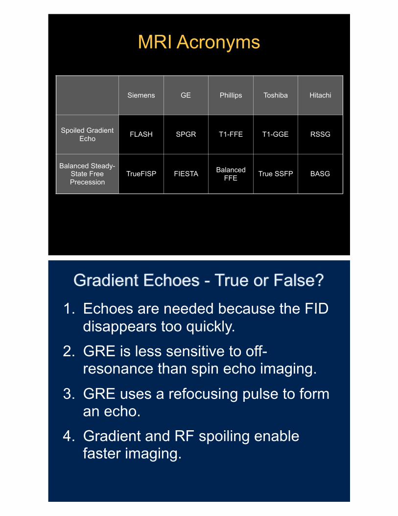
MRI Acronyms
Siemens GE Phillips Toshiba Hitachi
Spoiled Gradient Echo FLASH SPGR T1-FFE T1-GGE RSSG
Balanced Steady-State Free Precession
TrueFISP FIESTA Balanced FFE True SSFP BASG
Gradient Echoes - True or False?1. Echoes are needed because the FID
disappears too quickly. 2. GRE is less sensitive to off-
resonance than spin echo imaging.
3. GRE uses a refocusing pulse to form an echo.
4. Gradient and RF spoiling enable faster imaging.

Gradient Echoes & Fat
Chemical Shift - Type 1• Fat and water have
different Larmor frequencies – ~220Hz different at 1.5T – ~440Hz different at 3.0T
• Spatial position is related to spin frequency in MRI.
– Fat is more spatially mis-registered @ 3T
Chemical Shift – Fat (–CH2) is ~220Hz lower at 1.5T
Image Courtesy of Brian Hargreaves
“water” fat

GRE & Fat/Water Frequency
x
B0
Water Spins in a Uniform FieldWater spins precess at the same Larmor frequency in a uniform B0 field.
GRE & Fat/Water Frequency
x
Water Spins in a Gradient Field
B0
-Gx•x
+Gx•x
Water spins precess at different Larmor frequencies in a non-uniform B0 field.

GRE & Fat/Water Frequency
x
B0
-Gx•x
+Gx•x
Water & Fat Spins in a Gradient FieldFat Spins ~220Hz slower than water @ 1.5T
Spatial position is inferred from Larmor frequency. Chemical (frequency) shift produces and apparent spatial shift.
GRE & Fat/Water Frequency
x
B0
Signal Overlap
Signal Voids
-Gx•x
+Gx•x

GRE and Bandwidth
x
Higher bandwidths use stronger gradients and result in larger frequency differences along x. Chemical shift (frequency) is fixed for B0, therefore chemical shift (∆x) is a smaller percentage.
B0
-2Gx•x
+2Gx•x
GRE and Bandwidth
x
Signal Overlap
Signal Voids
B0
-2Gx•x
+2Gx•x
High bandwidth scans have less chemical shift.

Low Bandwidth High Bandwidth
Pile-Up
Void
GRE, Fat/Water & Bandwidth
Acquisition bandwidth is related to the speed with which an echo is acquired. If the bandwidth (speed) is high, then there is less time for chemical shift, less time for
signal acquisition (lower SNR), and a shorter TE/TR.
• High Bandwidth – Less chemical shift – Lower SNR – Short TE/TR
• Low Bandwidth – More chemical shift – Higher SNR – Longer TE/TR
Chemical Shift - Type 2
• Pixels are frequently a mixture of fat and water • Pixel intensity is the vector sum of fat and
water
Fat Water
+ >0In-Phase
+ =0Opposed-Phase
The TE controls the phase between fat and water.

GRE and Fat/Water PhaseIn-Phase Opposed-Phase
Dual-Echo Acquisition
GY
GX
RF
α
In-Phase
Out-of-Phase

In-phase and Out-of-phaseExample: 3 T abdominal scan
In-phase (3 T), TE = 2.6 msOut-of-phase (3 T), TE = 1.3 ms
Water Water
FatFat
IP
OP
Water Fat
Example: 3 T abdominal scan
In-phase (3T), TE = 2.6 ms Out-of-phase (3T), TE = 1.3 ms
2-Point Dixon

Which image is the in-phase image?
Images Courtesy of Scott Reeder
A. B.
Which image is the in-phase image?
Images Courtesy of Scott Reeder
A. B.In-Phase Opposed-Phase

Gradient Echoes - True or False?1. Fat and water precess at frequencies
that are >1000Hz different.
2. Fat and water are always out of phase.
3. Fat and water destructively interfere when they are in phase.
4. In-flowing spins are bright because they “see” hundreds of excitation pulses.
Gradient Echo – Summary
• Advantages – Fast Imaging Applications – Flexible contrast (T1 or T2*)
• Disadvantages – Off-resonance sensitivity – T2*-weighted rather than T2-weighted

ThanksKyung Sung, PhD
http://mrrl.ucla.edu/sunglab/
Images/Slides Courtesy of
Daniel Ennis, Ph.D.