lecture 9: bridging & switching - university of california ... · maxwait$1023$ frames$...
TRANSCRIPT

CSE 123: Computer NetworksStefan Savage
Lecture 9:Bridging & Switching

Lecture 9 Overview Finishing up media access
Ethernet Contention-free methods (rings)
Moving beyond one wire Link technologies have limits on physical distance Also frequently on number of hosts connected
Methods to interconnect LANs Repeaters and bridges Switching
2

Ethernet First local area network (LAN)
Developed in early ’70s by Metcalfe and Boggs at PARC Originally 1Mbps, now supports 10Mbps, 100Mbps, 1Gbps 10Gbps, 40Gbps, and 100Gbps flavors (400G in dev)
Currently the dominant LAN technology Becoming the dominant WAN technology
3

Classic Ethernet IEEE 802.3 standard wired LAN
(modified 1-persistent CSMA/CD) Classic Ethernet: 10 Mbps over coaxial cable
All nodes share same wire Max length 2.5km, max between stations 500m
Framing Preamble, 32-bit CRC, variable length data Unique 48-bit address per host (bcast & multicast addrs too)
nodes(wire)
CRC (4)Len (2)Preamble (8) Payload (var)Dest (6)Source (6) Pad (var)
4

Ethernet improvements
Problems with random delay with fixed mean Few senders = unnecessary delay Many senders = unnecessary collisions
Binary exponential back-off balances delay w/load First collision: wait 0 or 1 min frame times at random, retry Second time: wait 0, 1, 2, or 3 times Nth time (n<=10): wait 0, 1, …, 2n-1 times Max wait 1023 frames;; give up after 16 attempts
5

Capture Effect Randomized access scheme is not fair
Suppose stations A and B always have data to send They will collide at some time Both pick random number of “slots” (0, 1) to wait Suppose A wins and sends Next time they collide, B’s chance of winning is halved
» B will select from 0,1,2,3 due to exponential back-off
A keeps winning: said to have captured the channel
6

Ethernet Performance Much better than Aloha or CSMA in practice
Source of protocol inefficiency: still collisions More efficient to send larger frames
» Acquire the medium and send lots of data Less efficient if
» More hosts – more collisions needed to identify single sender» Smaller packet sizes – more frequent arbitration» Longer links – collisions take longer to observe, more wasted bandwidth
7

Contention-free Protocols Problem with fixed partitioning:
Inefficient at low load (idle channels)
Problem with contention-based protocols: Inefficient at high load (collisions)
Ideal(?): Contention-free protocols Try to do both by explicitly taking turns Can potentially also offer guaranteed bandwidth, latency, etc.
8

Contention-free ApproachesPolling
Master node “invites” slave nodes to transmit in turn
Request to Send (RTS), Clear to Send (CTS) messages
Problems: Polling overhead Latency Single point of failure (master)
Token Passing
Control token passed from one node to next sequentially.
Point-to-point links can be fast
Problems: Token overhead Latency Single point of failure (token)
9

Token Ring (802.5)
Token rotates “permission to send” around nodes Sender injects packet into ring and removes later
Maximum token holding time (THT) bounds access time Early or delayed token release Round robin service, acknowledgments and priorities
Monitor nodes ensure health of ring (alerts on failures)
A
BC
Dnodes
Direction oftransmission
10

FDDI (Fiber Distributed Data Interface)
Roughly a large, fast token ring First real use of fiber optics in a LAN 100 Mbps and 200km (FDDI) vs 4/16 Mbps and local (802.5) Dual counter-rotating rings for redundancy Complex token holding policies for voice etc. traffic
Token ring advantages No contention, bounded access delay Support fair, reserved, priority access
Disadvantages Complexity, reliability, scalability
Break!

Why Did Ethernet Win? Failure modes
Token rings – network unusable Ethernet – node detached
Good performance in common case
Completely distributed, easy to maintain/administer
Easy incremental deployment
Volume à lower cost à higher volume ….
12
Summary of Media Access How to divide shared channel among different users
Fixed partitioning (FDMA, TDMA, CDMA)» Guaranteed bandwidth for each user, but wasteful when not used and can’t allocate different bandwidth to different users
Contention-based protocols (CSMA, CSMA/CD)» Try and backoff if fail;; dynamic allocation of bandwidth on demand, works well at load load but collisions a problem at high load
Contention-free protocols (Token Ring, FDDI, RTS/CTS)» Explicit turn-taking;; strong guarantees on access time and can make bandwidth guarantees, but complex and fragile to failure
But… aren’t there limits to what we can do with one shared channel?
13

One shared link (a bus) limits scale in terms of: Distance (e.g., 2500 m for Ethernet) Number of nodes (1024 nodes) Performance (Capacity shared across all nodes)
A better alternative is to have multiple busses Each bus is of a limited size, scale, number of hosts, etc.
Need the ability to connect multiple busses together In other words move frames from one wire to another
14
Problems with Busses

Hubs/Repeaters Physical layer device
One “port” for each LAN Repeat received bits on one port out all other ports
LAN1 Hub LAN2
LAN3
15

Hub Advantages Hubs can be arranged into hierarchies
Ethernet: up to four hubs between any pair of nodes
Most of LAN continues to operate if “leaf” hub dies
Simple, cheap
16

Single collision domain No improvement in max throughput Average throughput < as # of nodes increases Why?
Still limited in distance and number of hosts Collision detection requirements Synchronization requirements
Requires performance homogeneity Can’t connect 10 Mbps and 100 Mbps networks
17
Still One Big Bus

Store and forward device Data-link layer device Buffers entire packet and then rebroadcasts it on other ports
Creates separate collision domains Uses CSMA/CD for access to each LAN (acts like a host) Can accommodate different speed interfaces (issues?) Separate CDs improves throughput (why?)
Can significantly improve performance Not all frames go everywhere. (Why did they with a hub?)
18
Bridges

Only rebroadcast a frame to the LAN where its destination resides If A sends packet to X, then bridge must forward frame If A sends packet to B, then bridge shouldn’t
D
C
B
A
bridge
LAN 1
Z
Y
X
W
LAN 2
19
Selective Forwarding

Need to know “destination” of frame Destination address in frame header (48bit in Ethernet)
Need know which destinations are on which LANs One approach: statically configured by hand
» Table, mapping address to output port (i.e. LAN) But we’d prefer something automatic and dynamic…
Simple algorithm: Receive frame f on port qLookup f.dest for output port /* know where to send it? */If f.dest foundthen if output port is q then drop /* already delivered */
else forward f on output port;else flood f; /* forward on all ports but the one where frame arrived*/
20
Forwarding Tables
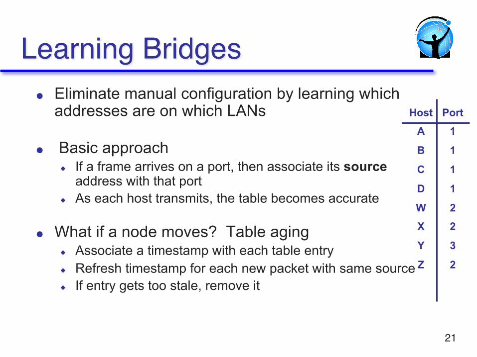
Learning Bridges Eliminate manual configuration by learning which addresses are on which LANs
Basic approach If a frame arrives on a port, then associate its sourceaddress with that port
As each host transmits, the table becomes accurate
What if a node moves? Table aging Associate a timestamp with each table entry Refresh timestamp for each new packet with same source If entry gets too stale, remove it
21
HostA
B
C
D
WX
Y
Z
Port1
1
1
1
22
3
2

Suppose C sends frame to D and D replies back with frame to C
C sends frame, bridge has no info about D, so floods to both LANs bridge notes that C is on port 1 frame ignored on upper LAN frame received by D
22
Learning Example

D generates reply to C, sends bridge sees frame from D bridge notes that D is on port 2
bridge knows C on port 1, so selectively forwards frame via port 1
23
Learning Example

Linear organization Inter-bridge hubs (e.g. CS) are single points of failure
Unnecessary transit (e.g. EE<->SE must traverse CS)
Backbone/tree Can survive LAN failure Manages all inter-LAN communication
Requires more ports
24
Network Topology

Learning works well in tree topologies
But trees are fragile Net admins like redundant/backup paths
How to handle Cycles? Where should B1forward packets destined for LAN A?
B3
A
C
E
DB2
B5
B
B7
KF
H
B4
B1
B6
G
25
An Issue: Cycles

For Next Time
Read 3.2-3.2.4 in P&D HW2 is delayed until Wednesday
26