lecture #9-10: communication methods - stanford …lecture #9-10: communication methods kunle...
TRANSCRIPT
EE183Olukotun
Handout #13Winter 2003
1
Lecture #9-10: CommunicationMethods
Kunle Olukotun
EE183
February 10, 2003
Lab Issues
• Lab 2 Writeup is due tonight at Midnight
• Lab 3 Questions?– The starter is available on the web
• ASM183
• Modelsim– Verilog simulation without synthesis
– Tutorial and installation instructions EE183 webpage
EE183Olukotun
Handout #13Winter 2003
2
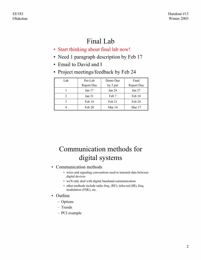
Final Lab• Start thinking about final lab now!
• Need 1 paragraph description by Feb 17
• Email to David and I
• Project meetings/feedback by Feb 24
Mar 17Mar 14Feb 284
Feb 24Feb 21Feb 143
Feb 10Feb 7Jan 312
Jan 27Jan 24Jan 171
Final
Report Due
Demo Due
by 5 pm
Pre-Lab
Report Due
Lab
Communication methods fordigital systems
• Communication methods• wires and signaling conventions used to transmit data between
digital devices
• we'll only deal with digital baseband communication• other methods include radio freq. (RF), infra-red (IR), freq.
modulation (FSK), etc.
• Outline– Options
– Trends
– PCI example
EE183Olukotun
Handout #13Winter 2003
3
Communication Options
• Orthogonal elements of communicationmethods
• number of wires - serial or parallel
• speed – bits/bytes/words per second
• timing methodology – synchronous or asynchronous
• number of destinations/sources – single or multiple
• arbitration scheme – daisy-chain, centralized,distributed
• Copper or Fiber fl New one!
Communication/PackagingHierarchy
• On-Chip• On a board• Between Boards• Between Racks/Boxes ‡ Inside a data center• How far you have to go makes a big difference on
what technology you select– Crossing a level of the hierarchy is a big deal– All solutions could be used at any level
• Engineering experience helps you decide
EE183Olukotun
Handout #13Winter 2003
4
One Wire
• Serial– single wire to transmit information one bit at a time
requires synchronization between sender and receiversometimes includes extra wires for clock and/orhandshaking
– good for inexpensive connections (e.g., terminals)– good for long-distance connections (e.g., LANs)– e.g.: RS-232, Ethernet, Apple desktop bus (ADB),
Philips inter-integrated circuit bus (I2C)
• Is this really one wire?– How does the current get back to you?
Many Wires
• Parallel– multiple wires to transmit information one byte or word
at a time
– good for high-bandwidth requirements (CPU tomemory)
– more expensive wiring/connectors/current requirements
– e.g.: SCSI, EISA bus (PCs), NuBus (Mac), PCI (innewer PCs and Macs), PCMCIA (in laptops)

EE183Olukotun
Handout #13Winter 2003
5
Speed/Bandwidth
• Serial• low-speed, cheap connections – RS-232 1.2K - 38Kbits/sec,
copper wire• medium-speed efficient connections – I2C 0 - 400Kbits/sec,
board traces• high-speed, expensive connections – Ethernet 1.5 -
10Mbytes/sec, co-axial cable– Today: 100 Mbit ethernet over twisted pair(telephone line)
• Parallel, low-medium-speed, not too wide• EISA bus, 20Mbytes/sec, 16 bits wide• SCSI bus, 5 - 40Mbytes/sec, 8 bits wide• NuBus, 40Mbytes/sec, 32 bits wide• PCI, 266 Mbytes/sec, up to 64 bits wide
Speed/Bandwidth
• Parallel, high-speed, very wide• memory systems in large multi-processors• DRAM interfaces• 500Mbytes/sec–few Gbytes/sec, 128 bits wide• LDT (AMD) is bringing this to PC
• Issues– length of the wires (attenuation, noise, capacitance)– environment (RF interference, noise)– current switching (spikes on supply voltages)– number and types of wires (cost of connectors, cross-
talk)

EE183Olukotun
Handout #13Winter 2003
6
Timing methodology• Asynchronous
• fewer wires (no clock)• clock recovery• no skew concerns• synchronization overhead• appropriate for loosely-coupled systems (CPU and peripherals)• common in serial schemes
• Synchronous• Clock wires and skew concerns• no synchronization overhead• can be high-speed if delays are small and can be controlled• appropriate for tightly-couple systems (CPU and memory)• Common in parallel schemes
Timing Issues
• clock period and wire delay
• synchronization and skew
• power consumption (directly related toamount of switching on high-capacitancewires)– Half of ASIC power can be in IOs

EE183Olukotun
Handout #13Winter 2003
7
Number of devicescommunicating
• Single source – single destination• point-to-point• cheap connections, no tri-stating necessary
• Single source – multiple destination• fanout limitations• addressing scheme to direct data to one destination
• Multiple source – multiple destination• arbitration between senders• tri-stating capability is necessary• addressing scheme• priority scheme• fairness considerations
Arbitration schemes• Daisy-chain or token passing
• devices either act or pass to next• fixed priority order (leads to fairness issues via starvation)• as many wires as devices
• Centralized• request to central arbiter• central arbiter implements priority scheme• wires from/to each device can be costly• can be dynamically changing priority/fairness
• Distributed• no central arbiter• common set of wires driven and observed by all devices• fixed priority/fairness scheme

EE183Olukotun
Handout #13Winter 2003
8
“Speeds and Feeds”
• Moore’s Law is only useful if you can getthe bits into and out of the system
• Traditional engineering tradeoff is thatparallel is preferred for short distances
• However, parallel wires have crosstalk andintersymbol interference at the speeds wewant—in short they look analog
Trends
• number of wires ‡ Serial via serdes (serializer,deserializer)
• timing methodology ‡ Clock and Data Recovery(CDR)
• speed ‡ 3Gbps per differential pair• number of destinations/sources ‡ point-to-point• arbitration scheme ‡ currently centralized but
moving to distributed• Copper or Fiber ‡ Both, depends on
distance—between racks/boxes is often fiber

EE183Olukotun
Handout #13Winter 2003
9
Trends for Boards and Beyond
Parallel Bus
C1 C2 C3 C4
4 portswitchC1
C2
C3
C4
Parallel multi-point bus
Serial point-to-pointwith switch
Switch keepsarbitration on chip
BusASIC
Will this happen onchip?
Plethora of Standards
• Xilinx Virtex Series IO Capabilities

EE183Olukotun
Handout #13Winter 2003
10
The Serialization ofCommunications
• Pin count is a key limiter for systems today– Need to route them to destination– Serdes power and knowhow is still an issue
• Many standards are moving to serdes• 3GIO(Pci)• Serial ATA (IDE hard disk)• AMD Hypertransport versus Intel Front Side Bus
(FSB)
• EE273 has lots more info
Case Study: PCI Bus– Origin of PCI Bus
• first version of the specification was released in June 1992• The current specification of the PCI bus is revision 2.2, which
was released in February 1999
– PCI is widely used• All PC systems today contain PCI slots,• Apple and workstations (SUN, SGI, HP)• Other bus standards based on PCI
– Benefits of PCI• Peak rate of 64 bit data path and 66MHz clock 524MBytes/sec.• 32 bit, 64-bit and 33MHz, 66 MHz versions, 133 MHz• Expandable to a large number of slots using PCI to PCI bridges.• Low Power 0-66MHz• Auto-configuration using software (no jumpers)

EE183Olukotun
Handout #13Winter 2003
11
PCI in a System
PCI Terminology
• Transaction– Address phase– Claiming transaction– Data phase(s)
• Burst Transfer– Transaction with two or more data phases
• Initiator– Bus master
• Target– Device addressed (slave)

EE183Olukotun
Handout #13Winter 2003
12
32 bit PCI Signals
PCIInitiatorPCI
InitiatorPCI
TargetPCI
Target
AD[31:0]
C/BE#[3:0]
PARFRAME#TRDY#IRDY#STOP#DEVSEL#
REQ#
GNT#
CLK CLKRST# RST#
IDESEL#
PCI Signals• System
• CLK• RST#: global async. reset signal
• Address/data/command• AD : multiplexed address/ data• C/BE#: multiplexed command/ byte enable
• Interface control• PAR: even parity signal• FRAME#: start transaction, end transaction• IRDY#: master ready to transfer data• TRDY#: target ready to transfer data• DEVSEL#: target must acknowledge transaction in 4 cycles• STOP#: used by target to abort transaction• IDSEL#: used by master for system configuration

EE183Olukotun
Handout #13Winter 2003
13
PCI Signals (cont)
• Arbitration• REQ#: used by bus master to request bus
• GNT#: used by arbiter to grant bus to a particular master
bus granted: when GNT# asserted and bus is idle
bus idle : FRAME# and IRDY# de-asserted
• Arbitration Algorithm• No algorithm given in PCI spec.
• Arbitration must be fair enough avoid deadlocks and starvation
PCI CommandsCommands set using C/BE# signals
– Memory read• Read one or more locations from target memory
– Memory read line• Read a cache line
– Memory read multiple• Read one or more cache lines
– Memory write• Write one or more locations in target memory
– I/O read and write• Read or write target I/O space
– Configuration read and write• Read or write target configuration space

EE183Olukotun
Handout #13Winter 2003
14
PCI Configuration Space
• 256 bytes long
• PCI standarddefinesfirst 64 bytes
PCI Read

EE183Olukotun
Handout #13Winter 2003
15
PCI Read Explanation
1. Master begins the transaction by driving FRAME# low, the requestedaddress on AD[31:0], and the requested command on C/BE#[3:0] (I/ORead, Memory Read, Memory Read Line, or Memory Read Multiple).
2. At Clock 1 the Target responds by asserting DEVSEL# low.3. At clock 2 both IRDY# and TRDY# are low, so the 1 st data word is read
(D0).4. At clock 3 the Master is not ready to accept the new word, since IRDY# is
high. The Target is ready to transfer the next word since TRDY# is low.Since not both are low, no data is transferred.
5. At clock 4 the master is able to receive data again, since IRDY# is low,and the 2nd data word is transferred. Since FRAME# was high during thislast cycle, both the Master and the Target end the cycle.
6. At clock 5 the Target tri-states AD[31:0] (turnaround), and drives TRDY#high. The Master also drives IRDY# high. This is done since IRDY# andTRDY# are sustained-tri-state lines
PCI Write

EE183Olukotun
Handout #13Winter 2003
16
PCI Write Explanation
1. At Clock 0 the Master begins the transaction by driving FRAME# low, therequested address on AD[31:0], and the requested command onC/BE#[3:0] (I/O Write, Memory Write, or Memory Write Line).
2. At Clock 1 the Target responds by asserting DEVSEL# low. Since this is awrite transaction, the master keeps driving AD[31:0] (this time with data.IRDY# is driven low to indicate data is ready for write. Since the Target isdriving TRDY# high, it is not ready to accept the data. C/BE#[3:0] areloaded with the appropriate byte enables.
3. At clock 2 both IRDY# and TRDY# are low, so the 1st data word iswritten (D0).
4. At clock 3 the Master is not ready to send a new word (as indicated by theinvalid content of AD[31:0]), so IRDY# is driven high. The Target isready to accept the next word since TRDY# is low, but since IRDY# ishigh, no data transfer takes place.
5. At clock 4 the master is able to write data again, since IRDY# is low, anddata is transferred. Since FRAME# was high during this last cycle, boththe Master and the Target end the cycle.
Split-Transaction Bus
• A split-transaction bus splits each transaction intotwo largely independent parts, a request (addresspart) and a reply (data part for reads). Replies mayappear in any order.
• Just as masters arbitrate to initiate a transaction onthe address bus, slaves must now arbitrate to puttheir reply on the data bus.
• Other transactions may intervene– Improves bandwidth dramatically– Response is matched to request– Buffering between bus and cache controllers

EE183Olukotun
Handout #13Winter 2003
17
Communications is Complicated
• Great opportunity for errors since yourdesign is by definition talking to someoneelse’s design
• “Be forgiving on the inputs andconservative on the outputs”
• Some smart CS person
– Applies to both logical and physical layer