lecture 5: orbit. king et al. appendix read satellite orbits at what location is the satellite...
Post on 20-Dec-2015
215 views
TRANSCRIPT

Lecture 5: Orbit

King et al. Appendix
• read

Satellite Orbits
• At what location is the satellite looking?
• When is the satellite looking at a given location?
• How often is the satellite looking at a given location?
• At what angle is the satellite viewing a given location?

Altitude classifications
• Low Earth orbit (LEO): Geocentric orbits ranging in altitude from 0–2000 km (0–1240 miles)
• Medium Earth orbit (MEO): Geocentric orbits ranging in altitude from 2000 km (1240 miles) to just below geosynchronous orbit at 35786 km (22240 miles). Also known as an intermediate circular orbit.
• High Earth orbit (HEO): Geocentric orbits above the altitude of geosynchronous orbit 35786 km (22240 miles).

• the satellite’s height, eccentricity, and inclination determine the satellite’s path and what view it will have of Earth.

Kepler’s laws
1. Satellites follow an elliptical orbit with the Earth as one focus
PerigeeApogee
Foci
3rd law (law of harmonics): The square of a planet's orbital period is proportional to its mean distance from the Sun cubed. The mathematical way to describe Kepler's 3rd law is:
P2 ~R3

Ellipse
• An ellipse is defined as follows: For two given points, the foci, an ellipse is the locus of points such that the sum of the distance to each focus is constant.
• BTW, Locus -- A word for a set of points that forms a geometric figure or graph

Physics for satellite

Centripetal Force, Gravity
When a body moving in a circle, from Newton's 2nd law there must be a force acting on it to cause the acceleration. This force will also be directed toward the centre and is called the centripetal force.
F1 = ma = mv2/r = mrω2
Where m is the mass of the body and v is the speed in the circular path of radius r
Newton's 2nd law
F2 = ma
T2= r342
Gme
g= GM/r2

Period of orbit
• Valid only for circular orbits (but a good approximation for most satellites)
• Radius is measured from the center of the Earth (satellite altitude+Earth’s radius)
• Accurate periods of elliptical orbits can be determined with Kepler’s Equation
T2= r342
Gme
Period of orbit
Gravitational constant Mass of the Earth
Radius of the orbit

The orbital period of a satellite around a planet is given by
where 0 = orbital period (sec)
Rp = planet radius (6380 km for Earth)
H = orbit altitude above planet’s surface (km)
gs = acceleration due to gravity (0.00981 km s-2 for Earth)
Definition of Orbital Period of a Satellite
T0 2(Rp H )Rp H
gs Rp2

Eccentricity
Eccentricity refers to the shape of the orbit. A satellite with a low eccentricity orbit moves in a near circle around the Earth. An eccentric orbit is elliptical, with the satellite’s distance from Earth changing depending on where it is in its orbit.

Orbital inclination
• Inclination is the angle of the orbit in relation to Earth’s equator. A satellite that orbits directly above the equator has zero inclination. If a satellite orbits from the north pole (geographic, not magnetic) to the south pole, its inclination is 90 degrees.

Types of orbits
• Sunsynchronous orbits: An orbit in which the satellite passes every location at the same time each day– Noon satellites: pass over near noon and midnight– Morning satellites: pass over near dawn and dusk– Often referred to as “polar orbiters” because of the
high latitudes they cross– Usually orbit within several hundred to a few
thousand km from Earth

Types of orbits
• Geostationary (geosynchronous) orbits: An orbit which places the satellite above the same location at all times– Must be orbiting approximately 36,000 km
above the Earth– Satellite can only “see” one hemisphere

Atmospheric Remote Sensing Sensors, Satellite Platforms, and Orbits
Atmospheric Remote Sensing Sensors, Satellite Platforms, and Orbits
• Satellite orbits and platforms
– Low Earth orbit
• Sunsynchronous and repeat coverage
• Precessing
– Geosynchronous orbit
• Sensor scanning modes
– Whiskbroom and pushbroom scanners
– Active and passive microwave radiometersNext lecture

Sun Synchronous (Near Polar)
• Video
Sun-Synchronous Orbit at 800km
http://www.youtube.com/watch?v=NCwLBlsAMNg
• Terra orbit -http://www.met.sjsu.edu/~jin/PersonalLib.html

Low Earth Orbit Concepts
Equator
South Pole
Ground track
Ascending node
Inclination angle
Descending node
Orbit
Perigee
Apogee
Orbit

Sun-Synchronous Polar Orbit
Satellite Orbit
Earth Revoluti
on
• Satellite orbit precesses (retrograde)– 360° in one year
• Maintains equatorial illumination angle constant throughout the year– ~10:30 AM in this example
Equatorial illuminatio
n angle

Sun-Synchronous Orbit of Terra

Spacing Between Adjacent Landsat 5 or 7 Orbit Tracks at the Equator

Timing of Adjacent Landsat 5 or 7 Coverage Tracks
Adjacent swaths are imaged 7 days apart

Polar-Orbiting Satellite in Low Earth Orbit (LEO)
Example from Aqua

A precessing low-inclination (35°), low-altitude (350 km) orbit to achieve high spatial resolution and capture the diurnal variation of tropical rainfall– Raised to 402 km in
August 2001
Tropical Rainfall Measuring Mission Orbit (Precessing)

TRMM Coverage
1 day coverage 2 day coverage

SatelliteAltitude
(km)Inclination
(°)Orbital Period
(min)Repeat
Coverage Orbits/dayJason-1 1336 66 112.3 10 12.8Meteor-3M/SAGE III 1020 99.5 105.5 13.7Landsat 1-3 907-915 99.2 103.1 18 14.0SPOT 832 98.7 101.5 26 14.2NOAA 850 98-99 102-104 11 14.0QuikScat 803 98.6 100.9 14.3ACRIMSAT 720 98.1 99.1 14.5Landsat 4-7 705 98.2 98.8 16 14.6Terra, Aqua, Aura 705 98.2 98.8 16 14.6
ICESat 600 94 96.6 – 14.9UARS 585 57 96.3 – 14.9ERBS 610 57 96.8 – 14.9SORCE 640 40 97.5 – 14.8TRMM 402 35 92.6 – 15.6TRMM 350 35 91.5 – 15.7
Orbital Characteristics of Selected MissionsLow Earth Orbit & Precessing Missions

Sunsynchronous image (SMMR)

Sunsynchronous image (AVHRR)

Types of orbits
• Geostationary (geosynchronous) orbits: An orbit which places the satellite above the same location at all times– Must be orbiting approximately 36,000 km
above the Earth– Satellite can only “see” one hemisphere


Video for Geo. satellite
• http://www.youtube.com/watch?v=_FfwTS3yClc

Geostationary Image (GOES-8)


Geostationary satellites
• GMS (Japan)– Geostationary Meteorological Satellite – Located over 140ºE longitude– Similar to older GOES satellites
• Insat (India)– Located over 74ºE longitude– Insat 1B similar to GOES-8/9
• Meteosat (European Union)– Located over 0º longitude
• FY 2 and FY 4 (China)

SectorSatellites in Orbit
(+mode) Operator LocationLaunch date Status
MTSAT-1R (Op) Japan 140°E 2/26/05 Fully functionalMTSAT-2 (B) Japan 145°E 2/18/06 Back-up to MTSAT-1RGOES-9 (B) USA/NOAA 160°E 5/99 Dissemination not
activatedEast-Pacific GOES-11 (Op) USA/NOAA 135°E 5/00 GOES-West
GOES-10 (B) USA/NOAA 60°W 4/97 South America coverageGOES-12 (Op) USA/NOAA 75°W 7/01 GOES-EastGOES-13 (P) USA/NOAA 89.5°W 5/06 In commissioning
Meteosat-6 (B)EUMETSAT 10°E 11/93 Rapid scan anomalyMeteosat-7 (B)EUMETSAT 0°E 2/97 To be relocated to 57.5°E
Meteosat-8 (Op)EUMETSAT 3.4°W 8/28/02 EUMETCASTMeteosat-9 (P)EUMETSAT 6.5°W 12/21/05 In commissioning
Meteosat-5 (Op)EUMETSAT 63°E 3/91 Functional but high inclination mode
GOMS-N1 (B) Russia 76°E 11/94 Standby since 9/98FY-2C (Op) China/CMA 105°E 10/19/04 Functional
Kalpana-1 (Op) India 74°E 9/12/02 DedicatedINSAT-3A (Op) India 93.5°E 4/10/03 Operational
West-Pacific
West-Atlantic
East-Atlantic
Indian Ocean
Geosynchronous Meteorological SatellitesWMO Member States

Geostationary satellites
• GOES 4-7 (USA)– Geostationary Operational
Environmental Satellite– Spin stabilized... pointing toward
Earth 5% of the time– Rotation rate of 100 rpm, 18.21
minutes are required to complete one full scan
– VAS (VISSR Atmospheric Sounder)
• Visible/Infrared Imaging Spin Scan Radiometer

Geostationary satellites
• GOES-8/(9)/10/11/12 (USA)– GHIS (GOES High Resolution
Interferometer Sounder)
– Sounder 2-3X more accurate
– 5 Visible/IR channels
– 18 IR sounder bands (channels)
– 3-axis stabilized... always pointing toward Earth
– 75ºW-GOES 12; 135ºW-GOES 11

•

What’s Next
• GOES-13 launced in 2006• GOES-O launched on 20 July 2008 • GOES-P launched on 30 May 2009• GOES-Q has no spacecraft manufacturer or
launch date (Cancelled)• GOES-R series of spacecraft is in the
formulation phase.

GOES-R Scheduled for 2014

GOES-8/10 diagram
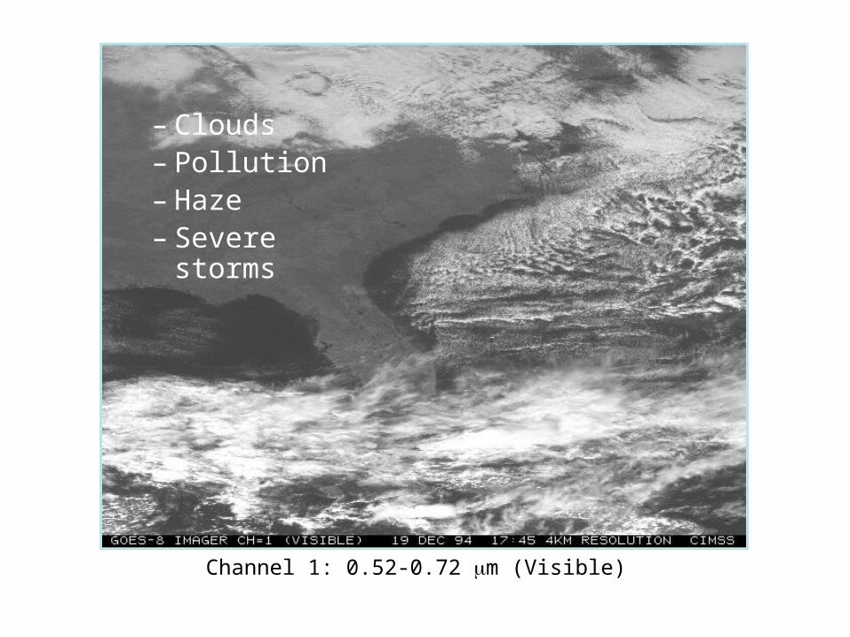
Channel 1: 0.52-0.72 m (Visible)
– Clouds– Pollution– Haze– Severe storms
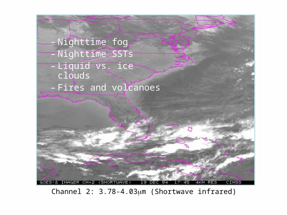
Channel 2: 3.78-4.03m (Shortwave infrared)
– Nighttime fog– Nighttime SSTs– Liquid vs. ice clouds– Fires and volcanoes

Channel 3: 6.47-7.02 m (Upper-level water vapor)
– Standard water vapor
– Mid-level moisture– Mid-level motion

Channel 4: 10.2-11.2 m (Longwave infrared)
– Standard IR channel– Winds– Severe storms– Heavy rainfall

Channel 5: 11.5-12.5 m (Infrared/water vapor)
– Low-level moisture– SSTs– Volcanic dust or ash

Sounder IR bands 2, 3, 4 and 5 (temperature)

Sounder IR bands 8, 10, 11 and 12 (water vapor)

FYI
• The following section is just FYI
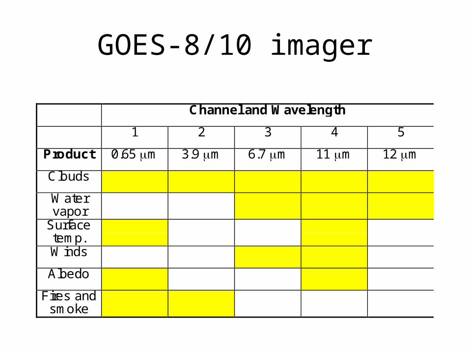
GOES-8/10 imager
Channel and Wavelength
1 2 3 4 5
Product 0.65 m 3.9 m 6.7 m 11 m 12 m
Clouds
Watervapor
Surfacetemp.Winds
Albedo
Fires andsmoke

GOES-8/10 imager
Channel and Wavelength
1 2 3 4 5
Product 0.65 m 3.9 m 6.7 m 11 m 12 m
Clouds
Watervapor
Surfacetemp.Winds
Albedo
Fires andsmoke

GOES-8/10 sounderResolution (km) Accuracy
Vertical Horizontal Absolute Relative
Temp.profile
3-5 50 2-3K 1K
Land temp. 10 2K 1K
SST 10 1K 0.5K
Moistureprofile
2-4 50 30% 20%
Totalmoisture
10 20% 10%
Cloudheight
2 layers 10 50mb 25mb
Cloudamount
10 15% 5%

GOES-8/10 sounderResolution (km) Accuracy
Vertical Horizontal Absolute Relative
Temp.profile
3-5 50 2-3K 1K
Land temp. 10 2K 1K
SST 10 1K 0.5K
Moistureprofile
2-4 50 30% 20%
Totalmoisture
10 20% 10%
Cloudheight
2 layers 10 50mb 25mb
Cloudamount
10 15% 5%

Non-Photographic Sensor Systems
• 1800 Discovery of the IR spectral region by Sir William Herschel. • 1879 Use of the bolometer by Langley to make temperature measurements of
electrical objects. • 1889 Hertz demonstrated reflection of radio waves from solid objects. • 1916 Aircraft tracked in flight by Hoffman using thermopiles to detect heat
effects. • 1930 Both British and Germans work on systems to locate airplanes from their
thermal patterns at night. • 1940 Development of incoherent radar systems by the British and United States
to detect and track aircraft and ships during W.W.II. • 1950's Extensive studies of IR systems at University of Michigan and elsewhere.
1951 First concepts of a moving coherent radar system. • 1953 Flight of an X-band coherent radar. • 1954 Formulation of synthetic aperture concept (SAR) in radar. • 1950's Research development of SLAR and SAR systems by Motorola, Philco,
Goodyear, Raytheon, and others. • 1956 Kozyrev originated Frauenhofer Line Discrimination concept. • 1960's Development of various detectors which allowed building of imaging and
non-imaging radiometers, scanners, spectrometers and polarimeters. • 1968 Description of UV nitrogen gas laser system to simulate luminescence.

Sunsynchronous satellites• TIROS (renamed NOAA) (USA)
– Advanced Very High Resolution Radiometer• 1.1km resolution (LAC) or 4km (GAC)
Band # Satellites:
NOAA-6,8,10 NOAA-7,9,11,12,14 1 0.58 - 0.68 m 0.58 - 0.68 m 2 0.725 - 1.10 m 0.725 - 1.10 m 3 3.55 - 3.93 m 3.55 - 3.93 m 4 10.50 - 11.50 m 10.3 - 11.3 m 5 band 4 repeated 11.5 - 12.5 m
Channel 3A (1.6 m) added to new AVHRR/3 sensor in spring 1996

AVHRR thermal IR imagery of Gulf Stream

AVHRR multi-channel SSTs

AVHRR Normalized Difference Vegetation Index
TIROS

– TIROS Operational Vertical Sounder (TOVS)• October 78 to present• Three units to TOVS: MSU, HIRS, SSU (Stratospheric
Sounding Unit)
– High Resolution Infrared Radiation Sounder (HIRS/2 & /3
• Vertical temperature profiles to 40km• 20 infrared bands
– Microwave Sounding Unit (MMU)• Vertical temperature profile to 20km• 4 microwave channels• Complements HIRS when clouds are present
Sunsynchronous satellites:TIROS/NOAA

MSU mid-troposphere temperatures

MSU mid-troposphere vorticity

– Advanced Microwave Sounding Unit (3 units)• AMSU-A1, AMSU-A2, AMSU-B • Replace MSU and SSU
Sunsynchronous satellites:TIROS/NOAA

http://poes.nesdis.noaa.gov/posse/
Total Precipitable Water
POES Satellite Soundings24 Hour Coverage - 2 Satellites

Gray: Clear AreasWhite/Blue: Clouds
Soundings Available for BothClear and Cloudy Conditions
POES Satellite SoundingsCoverage in Polar Regions

POES Satellite SoundingsIndividual Temperature/Moisture Profile

Sunsynchronous satellites
• Defense Meteorological Satellite Program (DMSP) (USA)– Operational Linescan System (OLS)
• Visible imagery (0.55km resolution)• Visible and thermal IR channels
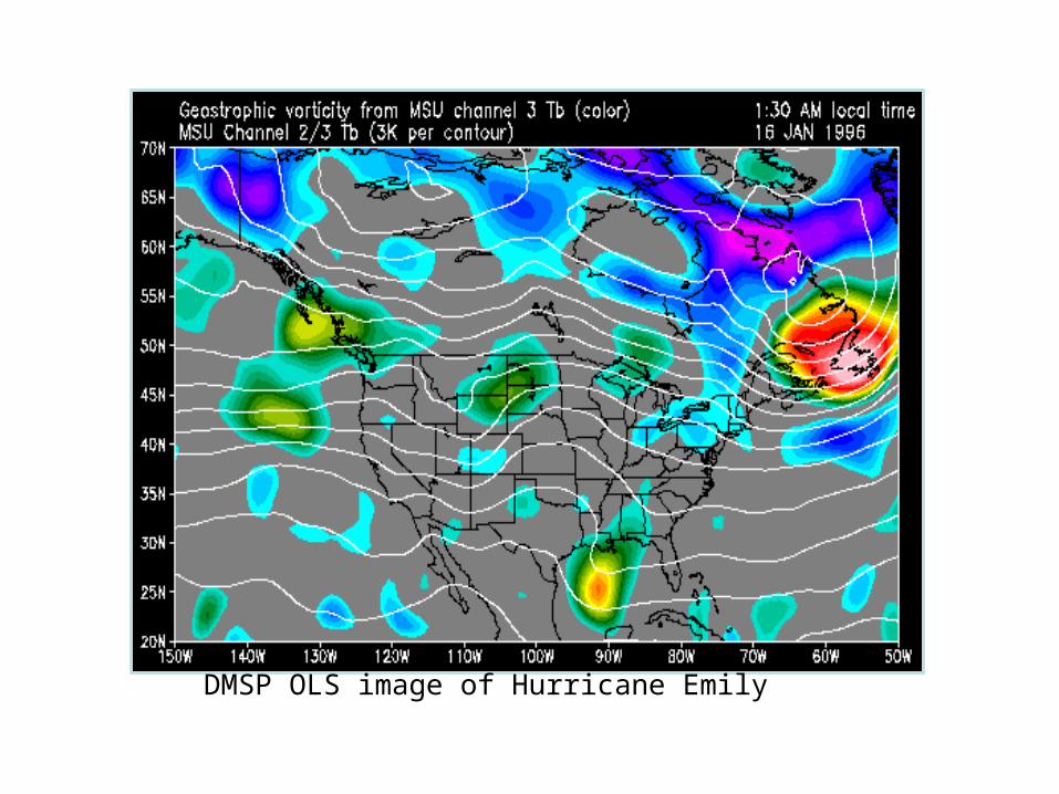
DMSP OLS image of Hurricane Emily

DMSP OLS image of city lights

– Special Sensor Microwave/Imager• 19, 22, 37 and 85 GHz channels• Uses include: snow cover, sea ice, precipitation
rate, oceanic wind speed, water vapor, soil moisture
• Similar sensors: SMMR and ESMR
– Microwave temperature sounder (SSM/T)– Microwave water vapor profiler (SSM/T2)
Sunsynchronous satellites:DMSP

DMSP SSM/I precipitation rates during the Blizzard of ‘93

NPOESS
• National Polar Orbiting Operational Environmental Satellite System
• Will converge NOAA, DoD and NASA missions in a next generation instrument.– Follow on to NOAA series of satellite
(AVHRR) and DoD DMSP series– Continues NASA’s EOS Terra and Aqua
missions • Launch 2009 with missions to 2018???

NPOESS instruments
1330 1730 2130
NPP
Visible/Infrared Imager/Radiometer Suite (VIIRS) X X X X
Conical Microwave Imager/Sounder (CMIS) X X X
Crosstrack Infrared Sounder (CrIS) X X X
Advanced Technology Microwave Sounder (ATMS) X X X
Space Environment Sensor Suite (SESS) X X X
Ozone Mapping and Profiler Suite (OMPS) X X
Advance Data Collection System (ADCS) X X
Search and Rescue Satellite Aided Tracking (SARSAT) X X X
Total Solar Irradiance Sensor (TSIS) X
Earth Radiation Budget Sensor (ERBS) X
RADAR Altimeter (ALT) X
Aerosol Polarimeter Sensor (APS) X
Survivability Sensor (SS) X X X

NPOESS Preparatory Mission
• NPP is a bridge between the EOS program and NPOESS for the development of the following sensors:– Advanced Technology Microwave Sounder (ATMS)– Cross-track Infrared Sounder (CrIS)– Ozone Mapping and Profiler Suite (OMPS)– Visible/Infrared Imager Radiometer Suite (VIIRS)
• Its mission is to demonstrate advanced technology and giving continuing observations about global change after EOS-PM (Terra) and EOS-AM (Aqua).
• Launch late ??