lecture 4 - welcome to delta...
TRANSCRIPT

Oct-15
Dr. A. Helba CIV 416E 1
A Guide to Designing Reinforced Concrete Water Tanks
Helba AlaaDr.
Roof slab
Wall
Floor slab
Tower supp. Sys.
Lecture 4

Oct-15
Dr. A. Helba CIV 416E 2
Load distribution on tank walls
Cylindrical wall
Rectangular wall
Analysis of Cylindrical Walls.
Using of Portland Cement Association tables.
A tour within (PCA) tables.
Lecture 4
H
pyv pyh
Load Distribution on Wall with Fixed Base
y
py = gw y = pyh + pyv
py
pmax = gw H
At a level at distance (y) from top of wall: py= gw y py is distributed to 2 components:

Oct-15
Dr. A. Helba CIV 416E 3
Case of a Rectangular Wall as T.W.S
ph max=
0.75 ph
H
ph max
pv ph
Load Distribution on Wall with Fixed Base
L1
L2
H/4 Plan
Case of a Square Wall as T.W.S
ph max=
0.75 ph H
ph max
pv max=gwH
Load Distribution on Wall with Fixed Base
L
L
H/4
pyh max Hal Moment and T
pyv max B. Moment (Vertical)
Mm (at middle)= phmaxL2 / 24
Mc (at corner) = phmaxL2 / 12
T (on each wall) = phmaxL / 2

Oct-15
Dr. A. Helba CIV 416E 4
Analysis of Walls in R.C. Tanks Case of Wall of any regular section (L)
Mm (at middle)= phL2 / 24
Mc (at corner) = phL2 / 12
T (on each wall) = phD / 2
pL2 / 24
pL2 / 12
L D L L
Case of Cylindrical Wall
H D
t
SEC. PLAN SEC. ELEV. – Load on Wall
t

Oct-15
Dr. A. Helba CIV 416E 5
py= pyh + pyv
Load Distribution & Deformation of cylindrical Wall fixed at base
D
py
H y
x
pyh x
pyh Ring Tension T (Horizontal)
pyv B. Moment (Vertical)
Load Distribution & Resulting Forces and Moment
At any level (y from top):
py = pyh + pyv
pyh Ring Tension T (Horizontal) pyv B. Moment (Vertical)
Cylindrical Walls
T – Diag. B.M.D.

Oct-15
Dr. A. Helba CIV 416E 6
py= pyh + pyv
x is the resulting radial deformation at level y due lateral pressure py
er is the resulting radial strain due to pyh . er= x/R
Deformation of cylindrical Wall fixed at base
D
py
H y
x
pyh x
py= pyh + pyv
T is the resulting horizontal tension at level y due to radial pressure pyh where T = pyh R My is the resulting vertical moment due to pyv
Resulting External Forces and Moments of cylindrical Wall
R
pyh x
MF
My
B.M.D due to pyv
t
py
H y
x

Oct-15
Dr. A. Helba CIV 416E 7
Load - Deformation Relationships of cylindrical Wall
Tint = Text
Then Ec x t / R = pyh R Hal Load component pyh = Ec x t / R2
= 4 Ec x t / D2
Val Load - Deformation Relationships of cylal Wall
Vertically
Transferred
component
x q El. Ld. My
Qy pyv
Slope q = dx / dy Elastic load M = EcI dq / dy = EcI d
2x / dy2
Shear Q = EcI d3x / dy3
Val Load component pyv = EcI d4x / dy4
= Ect3 x’’’’ / 12
D i f f e r e n t i a t i o n
I n t e g r a t i o n
Oct-15
Dr. A. Helba CIV 416E 8
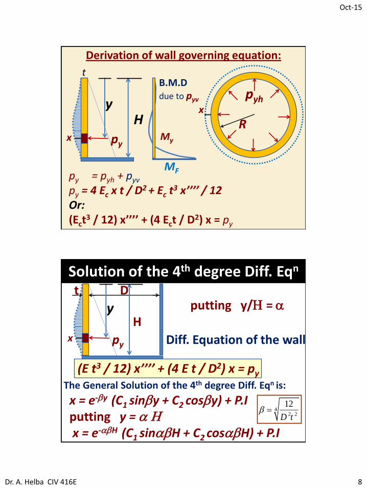
py = pyh + pyv
py = 4 Ec x t / D2 + Ec t3 x’’’’ / 12
Or: (Ect
3 / 12) x’’’’ + (4 Ect / D2) x = py
Derivation of wall governing equation:
MF
R py
H y
x
pyh x
My
B.M.D due to pyv
t
Solution of the 4th degree Diff. Eqn
(E t3 / 12) x’’’’ + (4 E t / D2) x = py The General Solution of the 4th degree Diff. Eqn is:
t D
H
Diff. Equation of the wall
x = e-by (C1 sinby + C2 cosby) + P.I putting y = a H x = e-abH (C1 sinabH + C2 cosabH) + P.I
42 2
12
D tb
putting y/H = a
py
y
x

Oct-15
Dr. A. Helba CIV 416E 9
x = e-ak (C1 sinak + C2 cosak) + P.I
The General Solution of the 4th degree Diff. Eqn is:
Substitute:
where k is a dimensionless factor
4244
2 2
1212
HH K
D tk b
2HK
D t
Using the Solution of the 4th deg. Diff. Eqn & using the Boundary Condition for each case, one can get T and M in wall at any a
a y / H = 0 1.0
Tables for Design of Cylindrical Tanks
For any circular tank a dimensionless
factor ktank is used to identify the tank
where:
- H is the internal height of tank
- D is the internal diameter of tank
- t is the wall thickness
k tank = H2 / D t

Oct-15
Dr. A. Helba CIV 416E 10
Tables for Design of Cylindrical Tanks
- use Portland Cement Association (PCA) tables
(A set of 20 tables) to analyze the elements of circular tanks (walls , roofs and floors).
k tank = H2 / D t
List of PCA 20 Tables (6/5/4/1/1/2/1)
• 6 for Tension in circular Walls. Tables I VI
• 5 for Moments in circular Walls. Tables VII XI
• 4 for Moments in circular Slabs. Tables XII XV
(1 without/3 with central support)
• 1 for Shear at base of Wall. Table XVI
• 1 for Load on central support. Table XVII
• 2 for stiffness (1 for Wall / 1 for Slab) XVIII - XIX
• 1 for Supplementary Coefficients for values of H2/Dt > 16 for Walls (13 tables 6/5/1/1).Table XX

Oct-15
Dr. A. Helba CIV 416E 11
Tension Moments
Slab Moments

Oct-15
Dr. A. Helba CIV 416E 12
Range of H/D vs values of the dimensionless factor H2 / Dt
H2/Dt = (H/D)(H/t)
Assume t = H/15 to H/20 say H = 16 t
Ktank = H2/Dt 16 (H/D) H/D Ktank/16
The 20 Tables consider 4 ranges of H2/Dt as:
0.4 2 step 0.4 (5 values) Shallow
3 8 step 1 (no 7) (5 values)
10 16 step 2 (4 values)
20 56 step 4/8 table XX (6 val.) Deep
Range of H/D vs values of the dimensionless factor H2 / Dt
Ktank D/H 0.4 2 40 8
3 8 5.33 2
10 16 1.6 1
20 56 0.8 2/7

Oct-15
Dr. A. Helba CIV 416E 13
Example on using PCA Tables
• For a circular tank with internal diameter of 8m , internal height of 4 m , and wall thickness of 0.40 m , then ,
• For Wall :
D = 8 m
H = 4 m
t = 0.40 m
K tank = H2 / Dt = (4)2 / (8 x 0.40) = 5
K tank = 5
Table I

Oct-15
Dr. A. Helba CIV 416E 14
+ ve tension
- ve compression
gw = 10 kN/m3
R = D/2
Table I
coeffs. for Tension in Circular Rings / Triangular Load / Fixed base , free top.
0.0 H 0.1 H 0.2 H 0.3 H 0.4 H 0.5 H 0.6 H 0.7 H 0.8 H 0.9 H 1.0 H
Fixed Base
Free Top
Table I

Oct-15
Dr. A. Helba CIV 416E 15
Distribution of Tension along H Example: Ktank = H2/Dt = 10 +ve sign means tension
I II
Distribution of Tension along H Example: Ktank = H2/Dt = 10 +ve sign means tension
III IV

Oct-15
Dr. A. Helba CIV 416E 16
Distribution of Tension along H Example: Ktank = H2/Dt = 10 +ve sign means tension
V VI
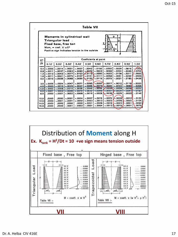
+ ve tension outside
- ve tension inside
Table VII
coeffs. for Moment in Cylindrical Wall / Triangular Load / Fixed base , free top.
0.0 H 0.1 H 0.2 H 0.3 H 0.4 H 0.5 H 0.6 H 0.7 H 0.8 H 0.9 H 1.0 H
Fixed Base
Free Top
Oct-15
Dr. A. Helba CIV 416E 17
Distribution of Moment along H Ex. Ktank = H2/Dt = 10 +ve sign means tension outside
VII VIII

Oct-15
Dr. A. Helba CIV 416E 18
Distribution of Moment along H Ex. Ktank = H2/Dt = 10 +ve sign means tension outside
Comparison between tables VII and VIII
VII VIII
Distribution of Moment along H Ex. Ktank = H2/Dt = 10 +ve sign means tension outside
IX

Oct-15
Dr. A. Helba CIV 416E 19
Distribution of Moment along H Ex. Ktank = H2/Dt = 10 +ve sign means tension outside
X XI
Summary
PCA
Tables of Tension
and Moments
in circular Tanks
II + IV