lecture 4 – profibusdixon.hh.se/urbi/scada/scada_lecture4.pdf · profibus-fms (fieldbus message...
TRANSCRIPT


2
Profibus – Outline
Introduction
Profibus-DP • Physical Layer
• Link Layer
• Application Layer

3
Profibus – Introduction
Three different versions of PROFIBUS exist: PROFIBUS-FMS (Fieldbus Message Specification) is used
based on the Client-Server model for the communication between automation devices (control level).
PROFIBUS-DP (Decentralized Periphery) is used for fast remote inputs and outputs, to connect sensors and actuators to a controlling device.
PROFIBUS-PA (Process Automation) is used for the connection of field devices and transmitters to a process control device. It allows intrinsic safe transmission and power on the line. Parameters and function blocks are defined covering the need of the process engineering.

4
Profibus – Introduction
5
PROFIBUS-DP-Introduction
PROFIBUS-DP (Decentralized Periphery)

6
PROFIBUS-DP-Introduction
7
Profibus-DP – Physical layer
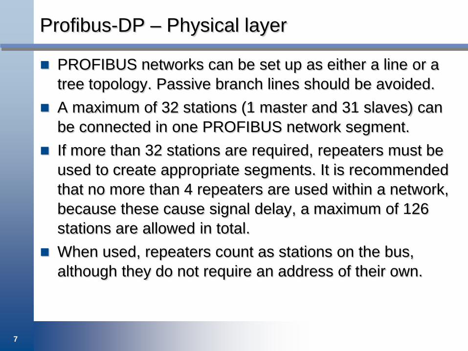
PROFIBUS networks can be set up as either a line or a tree topology. Passive branch lines should be avoided.
A maximum of 32 stations (1 master and 31 slaves) can be connected in one PROFIBUS network segment.
If more than 32 stations are required, repeaters must be used to create appropriate segments. It is recommended that no more than 4 repeaters are used within a network, because these cause signal delay, a maximum of 126 stations are allowed in total.
When used, repeaters count as stations on the bus, although they do not require an address of their own.
8
Profibus-DP – Physical layer
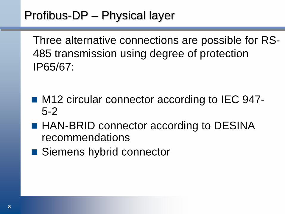
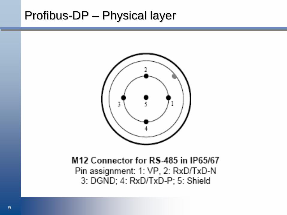
M12 circular connector according to IEC 947-5-2
HAN-BRID connector according to DESINA recommendations
Siemens hybrid connector
Three alternative connections are possible for RS-485 transmission using degree of protection IP65/67:
9
Profibus-DP – Physical layer

10
Profibus-DP – Physical layer

11
Profibus-DP – Physical layer

12
Profibus-DP – Physical layer
Shielded twisted pair, optic fiber, manchester bus powered (MBP).
Various transmission rates 9.6 kbit/s up to 12 Mbit/s.

13
Profibus-DP – Physical layer

14
Profibus-DP – Physical layer
15
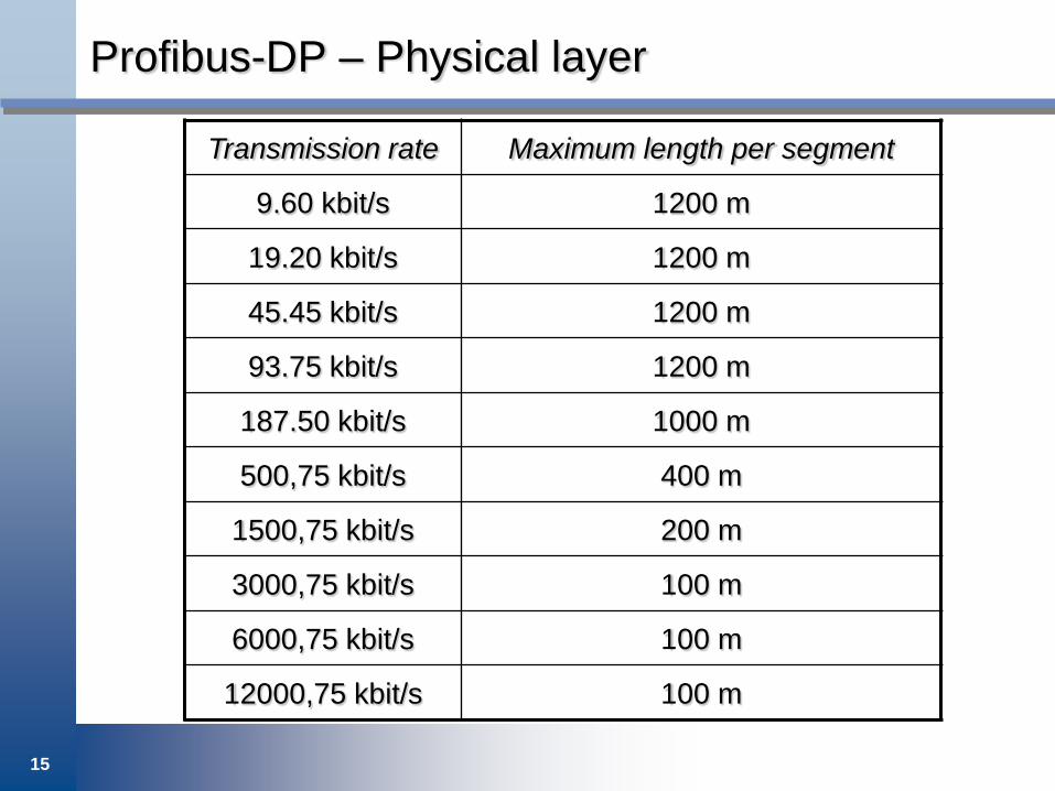
Profibus-DP – Physical layer
Transmission rate Maximum length per segment
9.60 kbit/s 1200 m
19.20 kbit/s 1200 m
45.45 kbit/s 1200 m
93.75 kbit/s 1200 m
187.50 kbit/s 1000 m
500,75 kbit/s 400 m
1500,75 kbit/s 200 m
3000,75 kbit/s 100 m
6000,75 kbit/s 100 m
12000,75 kbit/s 100 m

16
Profibus-DP – Link layer
At the link protocol level, ProfiBus and its versions DP-V0, DP-V1 and DP-V2 offer a broad spectrum of services, which enables optimum communication for different applications.
DP-V0 is the cyclic master-slave polling, which is time deterministic .
DP-V1 adds acyclic communication for parameter assignment, configuration, and alarm handling.
DP-V2 isochronous slave mode and direct slave-to-slave communication.

17
Profibus-DP – Link layer
A Profibus-DP system uses a bus master to poll slave devices distributed in a multi-drop fashion on EIA-485.
A Profibus-DP slave is any pheripheral device (I/O transducer, valve, network drive, or other meassuring device) which process information and sends it to the master.
Profibus-DP supports monomaster and multimaster systems
In a multimaster system each master represents an independent subsystem
The masters are coordinating themselves by passing a token from one master to the next master and so forth.

18
Profibus-DP – Link layer

19
Profibus-DP – Link layer

20
Profibus-DP – Link layer

21
Profibus-DP – Link layer
DP master Class 1 (DPM1) is a central controller that cyclically exchange information with the distributed slaves. • Tyical devices are PLCs or PCs
DP master Class 2 (DPM2) is a device for configuring,
maintenance and diagnostics. • Tyical devices are laptops equipped with software for
configuration, maintenance and diagnostics.

22
Profibus-DP – Link layer
The acyclic (DP-V1) forms the key parameterization and calibration of the field devices over the bus during runtime and the introduction of confirmed alarm messages.
Transmission of acyclic data is performed parallel to cyclic data with lower priority often with a master class 2 device.
23
Profibus-DP – Link layer

24
Profibus-DP – Link layer
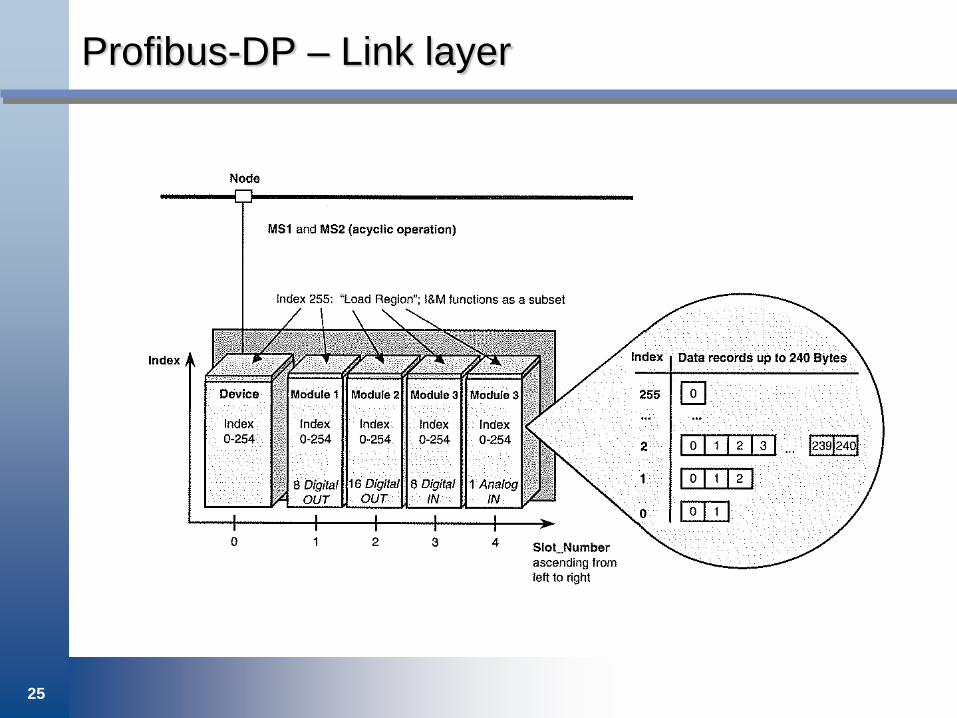
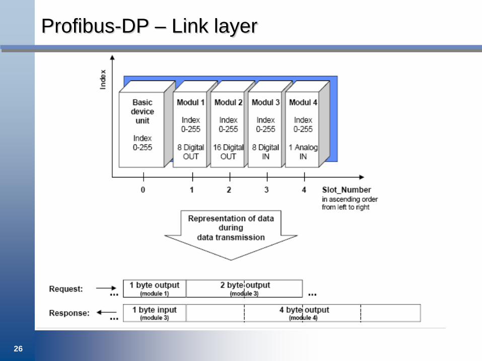
Adressing with slot and index is used for both cyclic and acyclic data.
When addressing specific data, Profibus assumes that the hardware is modular or can be structured in functional units, so called modules.
The slot number adresses the module and the index number adresses the specific data structure.
25
Profibus-DP – Link layer
26
Profibus-DP – Link layer

27
Profibus-DP – Application layer
28
Profibus-DP – Application layer

29
Profibus-DP – Application layer
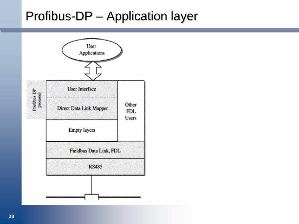
The Profibus DP communication profile protocol (application layer) comprises two fundamental applications, namely the user-interface and the direct data link mapper.
The user-interface represents the core of the protocol and is responsible for the correct execution of all operations foreseen by the standard.
The direct data link mapper has the task of mapping the requests coming from the user-interface onto FDL services; for this purpose, it uses two different services, namely the Send and Request Data with reply (SRD) and the Send Data with No acknowledge (SDN).

30
Profibus-DP – Application layer
SRD is a confirmed connectionless service which allows for the sending of up to 246 octets; the response frame of such a service can also carry up to 246 octets of data.
SRD is used for all the Profibus DP functions which involve data transmission between master and slaves, such as cyclic data exchange, diagnostic, parameterisation, acyclic read and write, etc.
SDN is a non-confirmed connectionless service which is used by the Profibus DP protocol in order to issue global control commands from master to slave.
31
Profibus-DP – Application layer
The FDL services used by the user interface can either be of high or low priority depending on the Profibus DP functions they implement. For example, a master implementing the cyclic data exchange function uses a high-priority SRD frame to send the output values to a slave.
The latter responds with a low priority SRD frame carrying the input data. The only exception to such a rule is when the slave has to signal the presence of a diagnostic message: in this case, it responds with a high-priority SRD frame.
FDL users different from the DP protocol could either be the FMS protocol or, more generally, applications using the FDL services.

32
Profibus-FMS – Application layer
PROFIBUS-FMS (Fieldbus Message Specification)
33
Profibus-FMS – Application layer

34
Profibus-FMS – Application layer
The FMS Communication Profile is designed for communication at cell level. At this level, programmable controllers (PLCs and PCs) communicate primarily with each other.
In this application area a high degree of functionality is more important than fast system reaction times.
The communication model of Profibus-FMS is based on the definition of a Virtual Field Device. This is the part of a device that is reachable by the communication system.
The PROFIBUS-FMS communication model permits distributed application processes to be unified into a common process by using communication relationships.
35
Profibus-FMS – Application layer
All accessible values, variables are listed in a so called object dictionary, which itself can be read out over the bus.
The object dictionary holds index, name, type of each variable.
That portion of an application process in a field device which can be reached via communication is called a virtual field device (VFD).
All communication objects of an FMS device are entered in the object dictionary (OD).
The object dictionary contains description, structure and data type, as well as the relationship between the internal device addresses of the communication objects and their designation on the bus (index/name).

36
Profibus-FMS – Application layer

37
Profibus-FMS – Application layer
The FMS application layer consists of the following´parts: The Fieldbus Message Specification (FMS)
The Lower Layer Interface (LLI)

38
Profibus-FMS – Application layer
Static communication objects are entered in the static object dictionary.
They are configured once and cannot be modified during operation.
FMS recognizes five types of communication objects: • Simple Variable • Array (series of simple variables of the same type) • Record (series of simple variables of different types) • Domain • Event (event message)
Dynamic communication objects are entered in the dynamic section of the object dictionary. These can be modified during operation.

39
Profibus-FMS – Application layer
Logical addressing is the preferred method of addressing for the objects. Accessing is performed with a short address (the index).
Confirmed services can only be used for connection-oriented communication relationships.
Unconfirmed services can also be used on connectionless communication relationships (broadcast and multicast).

40
Profibus-FMS – Application layer
Context Management services are for establishing and terminating logical connections.
Variable Access services are used to access variables, records, arrays or variable lists.
Domain Management services are used to transmit large memory areas. The data must be divided into segments by the user.
Program Invocation Management services are used for program control.
Event Management services are used to transmit alarm messages. These messages can also be sent as broadcast or multicast transmissions.

41
Profibus-FMS – Application layer
VFD Support services are used for identification and status polling. They can also be sent spontaneously at the request of a device as multicast or broadcast transmissions.
OD Management services are used for read and write access to the object dictionary.

42
Profibus-FMS – Application layer