lecture 33 inductor · pdf filelecture 33 inductor design ... energy taken from the input in...
TRANSCRIPT

1
LECTURE 33Inductor Design
A. Overview of Copper versus Core Loss in Inductors1. Core Material Limitations2. Core Materials Compared3.“Filter” Inductor Design via Erickson’s FourStep Design Rules
4. Ten Commandments For Inductor Design
5. Summary
B. Inclusion of Core Losses and Relation to WireWinding Losses
1. Sinusoidal Flux Density B(wt) Driving the Core
2. Bpeak ~ vdt∫ =NA NAc c(core)
λ
THIS ALSO SAYS N~ 1/B that is as Bdecreases the number of turns will increase3. Tailoring Bopt for Minimizing Total Losses:
a. Trading Fe vs Cu to Achieve Minimum TotalLoss

2
b. N↑ makes for larger I2R(wire) lossesc. N↓ makes for higher Bpeak and more core
lossesThe various core geometry’s are shown below
For a term paper on Integrated Inductor Design See asa starting point the article “LAYOUT OFINTEGRATED RF SPIRAL INDUCTOR” inCircuits and Devices March 1998 pgs 9-12

3
LECTURE 33Inductor Design Methodology
A. Overview of Copper versus Core LossesFor HW#1 do problems 14.1(easy) and 14.5(harder)
An inductor is a device whose purpose is to store and releaseenergy. A filter inductor uses this capability to smooth the currentthrough it and a two-turn flyback inductor employs this energy storage inthe flyback converter in-between the pulsed current inputs. The high µcore allows us to achieve a large value of L = µN2Ac/lc with small Ac andlc so large L values are achieved in small volumes. However, high µ willlimit the maximum energy storage in the core with no air gap. Since themagnetic core material itself is incapable of storing significant energy,energy storage is accomplished in a non-magnetic air gap(s) in series withthe core. These gaps minimize the inductor variations caused by changesin core properties and help avoid core saturation. If non-linear L(i) isdesired, as it is in magnetic amplifers, it can also be achieved with astepped or tapered air gap as shown below:
Air Gap
φ
Both core and wire winding losses as well as saturation effects establishdesign rules for those who “wind their own inductors” as shown below.Limitations of magnetic cores are crucial to good inductor design1. Core Material Limitations: In dc applications, inductors are
primarily thought of as current operated devices. Too large a current,will saturate the magnetic core via ampere-turn limits set by ni<BSATAC ℜ , this means ni <BSAT/µ . This limit on IMAX will in turnlimit the maximum energy that can be stored in an ungappped core to

4
B2(SAT) l(core)A(core) /2µ.A convoluted inter-dependence of the wire current and the magnetic
field in a transformer core is as follows. The volt-sec limit says that B(core)= λp =∫ LV dt /N AC. Hence, we find that N~1/B and later we willemploy N2~ 1/B2
in relations for the copper loss to show PCu ~1/B2.
As regards the inductor voltage applied without considering theequivalent series resistance rL, iL on a DC basis will continue to increasewith a DC VL ,since all of the applied voltage appears across vL. With rL
the inductor current increases until iLrL equals the input voltage. Againthe B-H curve of the inductor core looks like a ∫ELdt versus IL curve asshown below. At high ∫Edt,I → ∞ where the core saturates and L → 0. For a flux or B change to occur a time interval is required over which theapplied inductor voltage is applied.
In high frequency PWM applications, the major magnetic corematerial limitations are: 1. Flux Density Saturation and 2. Core losses,both of which depend upon flux swing and applied frequency of the flux. In these applications inductor windings are usually driven withrectangular voltage waveforms derived from low impedance sources. Since the voltage, pulse width, and number of turns are quite accuratelyknown, it is easy to apply Faraday’s Law to determine the maximum fluxswing and appropriately limit it. . In the case of a sinusoidal voltage,Faraday’s law gives V= N dϕ / dt =Nω AC BSAT. Hence V/ωNAc must beless than BSAT.
5
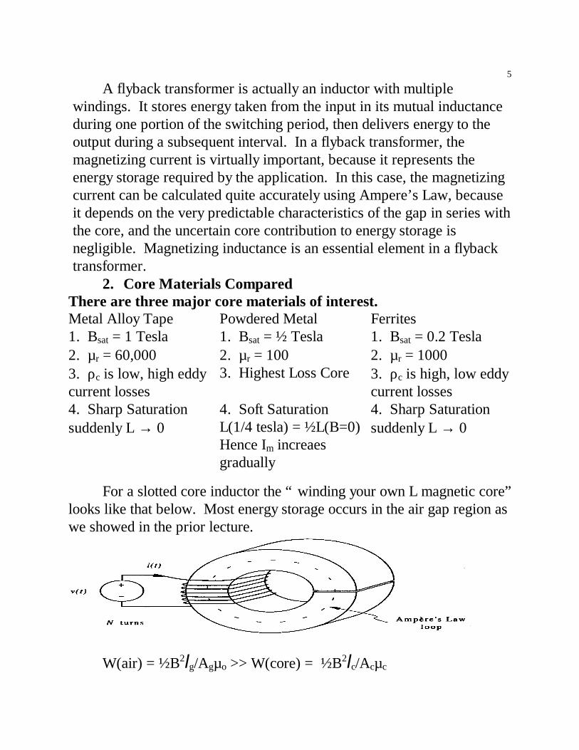
A flyback transformer is actually an inductor with multiplewindings. It stores energy taken from the input in its mutual inductanceduring one portion of the switching period, then delivers energy to theoutput during a subsequent interval. In a flyback transformer, themagnetizing current is virtually important, because it represents theenergy storage required by the application. In this case, the magnetizingcurrent can be calculated quite accurately using Ampere’s Law, becauseit depends on the very predictable characteristics of the gap in series withthe core, and the uncertain core contribution to energy storage isnegligible. Magnetizing inductance is an essential element in a flybacktransformer.
2. Core Materials ComparedThere are three major core materials of interest.Metal Alloy Tape Powdered Metal Ferrites1. Bsat = 1 Tesla 1. Bsat = ½ Tesla 1. Bsat = 0.2 Tesla2. µr = 60,000 2. µr = 100 2. µr = 10003. ρc is low, high eddycurrent losses
3. Highest Loss Core 3. ρc is high, low eddycurrent losses
4. Sharp Saturationsuddenly L → 0
4. Soft SaturationL(1/4 tesla) = ½L(B=0)Hence Im increaesgradually
4. Sharp Saturationsuddenly L → 0
For a slotted core inductor the “ winding your own L magnetic core”looks like that below. Most energy storage occurs in the air gap region aswe showed in the prior lecture.
W(air) = ½B2lg/Agµo >> W(core) = ½B2lc/Acµc
6
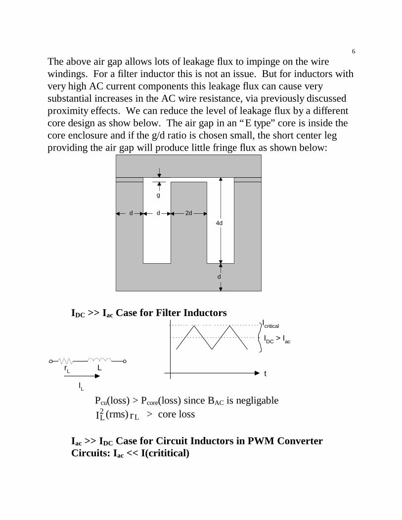
The above air gap allows lots of leakage flux to impinge on the wirewindings. For a filter inductor this is not an issue. But for inductors withvery high AC current components this leakage flux can cause verysubstantial increases in the AC wire resistance, via previously discussedproximity effects. We can reduce the level of leakage flux by a differentcore design as show below. The air gap in an “E type” core is inside thecore enclosure and if the g/d ratio is chosen small, the short center legproviding the air gap will produce little fringe flux as shown below:
2ddd
d
4d
g
IDC >> Iac Case for Filter Inductors
IL
rL Lt
IDC > Iac
Icritical
Pcu(loss) > Pcore(loss) since BAC is negligable
L2
LI (rms) r > core loss
Iac >> IDC Case for Circuit Inductors in PWM ConverterCircuits: Iac << I(crititical)

7
rL L t Iac dominates
Ptotal loss = Pcu(loss) + Pcore(loss)Herein we will learn to trade Fe vs Cu in order to minimize the total loss.That is we can find an optimum number of turns of wire that provideminimum total loss. If N is too high I2R wire losses dominate. While ifN is too low Bpeak = ∫Edt/NAc will rise and core losses dominate.The question is now how do we rationally trade off copper losses and corelosses to achieve the desired inductor for the specific circuit use.While the graph below illustrates the balance needed to achieve minimumtotal loss, we will not fully understand this plot till lectures 34 –35.
BBopt
PT
More Culoss
Pcu ~ 1/B2
Surprise!result only
true fortransformers
As B we findMore Core
lossesPcore ~ B2 or Bx
as expected
for minumum loss
3. “Filter” Inductor Design via Ericksons Four Step Design Rules
We tailor the inductor design to the switched mode converter circuittopology. Design considerations for inductors include:
n core size and permeabilityn effects of air gaps on reluctance and L linearity as well as
the sensitivity of L to changes in the coren core loss limitsn saturation values of flux density in the chosen materialn core window size (for allowing all needed wire windings)n current density allowed in wire windings

8
n maximum values of ac voltage, dc volt-sec, and dc currentn operating frequency
1st Select core via the emperical Kg factorBoth hysteresis and eddy current core loss effects in inductors are causedby time-varying flux. If an inductor carries a constant dc current belowits saturation limit, the core flux will be constant, and the hysteresis andeddy current losses of the core will be zero. In practice any switch modeconverter has large current ripple in the inductors, at the switchingfrequency. The flux variation will be follow the AC current. Magneticmaterial can handle only a limited loss per unit volume without gettingtoo hot. Losses of 1 W/cm3 are usually considered high for ferrites, andvalues in the range of 0.2 W/cm3 are more common in well designedcores. At any rate we can translate circuit variations into a singleparameter which helps to specify the core needed as shown in Lecture 32
[ ]g
2max2
pk2
u
8 5K > L I (wire)
B R K * 10 cm
ρ
Get L, R, Imax from PWM converter electrical specsGet Bpk, Ku from manufacturers core and wire specs respectively. Thecore geometry gives us both Ac(core) and WA(wire winding area) as wellas the mean length of turn wound on the core.
2nd Spec the air gap to be cut in the inductor core
go max
2
pk c =
L IB A
[m]lµ
As an alternative to the gap size, lg, we can specify the AL, or specificinductance in mH per turn2, factor for an inductor core. Nw is the numberof wire turns and ℜ c(core) is core reluctance including the airgap.
ℜℜ≡
turnmH = 1 = L A 1
2NLccw
- We arbitrarily fix N @ 1000 turns as core
manufacturers do so in their AL specifications.1 < AL < 1000; AL is typically 100 for N = 1000 turns.

9
You spec AL - Core Manufacturer will cut lg to size to meet your spec’s
3rd Spec # of wire turns. No fractional turns are allowed makingthis an iterative procedure
N = L IB A
max
pk cw
4th Choose wire insulation, wire type and current carrying area orAWG# size
Area Wire < uK (window area)N
All the wire wound on a given core must fit into its winding window, theopening for wire turns. The window also must hold insulation and anystructure on which the wire is mounted. In practice, only about 50% ofthe window area can actually carry active conductor, as the rest is voids orwire insulation. This fraction is called fill factor. In a two-windingtransformer, this means that each winding can fill not more than 25% ofthe total window area.
That is given the wire winding area, WA, and the required numberof turns we set the required wire size. We usually use AWG #’s insteadof wire current area to specify a wire. This choice of wire size will bemodified by high frequency skin effects as we will show later. Wire sizeis an important aspect of the inductor design since a given wire canhandle only a limited current density to avoid excessive power loss. Thewire-winding window of a given core must have enough area so thatcopper wire of a given diameter can be used and all the required numberof turns fit. We do this to avoid excessive Ohmic heating of the wire sowire loss influences key details in magnetic core geometry choices. Foran inductor design, core saturation primarily limits the amp-turn valuespossible but the current density limit in the wire also represents an amp-turn limit. A trade-off rule results.
Consider what happens if the rule is violated. If the core window istoo small, the wire size chosen could be too small for the required current

10
and the wire will overheat before the saturation amp-tum limit of themagnetic core is reached. If the wire-winding window is too large, thencore saturation will be reached prematurely and the copper winding mightbe underutilized. Core size sets the mean length of turn required toencircle the core and hence the length per turn of the wire.
Rwire = (resistance per meter of the wire) x (length per turn) X NOr alternatively R=ρN (MLT)/AW(wire). MLT depends on coregeometry. Cores made of sectioned structures tend to be easier to windwith automated wire winding machines than toroids. For toroid cores,windings are often designed to form a single layer of copper materialaround the inside of the core. This keeps the device small and minimizesflux leakage. For other core shapes, windings often use the largest wirethat will fit conveniently into the window. This minimizes losses, andmaximizes the power rating.
3. General Inductor Design via Ten Design Rules(SKIP THISSECTION IF YOU ARE AN UNDERGRADUATE)
a. Overview of ten step L design sequence
Start L Irms and f required by PWM convertercircuit.1. T(core surface) }In steps 1-2 the }Energy and heat2. Stored energy required}flow requirements ~1/2 Li2 }help chooses both }material type and3. From tables of cores vs}geometric shape 1/2 Li2 }of the required }core to wind wire4. Thermal Analysis }upon. T(surface), T(ambient)

11
Steps 5 and 6 quantify:Bac waveform in the core from core dataspecifies eddy current core loss
Peak B is crucial to hysteresis lossB(peak) < Bsat
Winding parameters for copperwire
MaximumLmax = N2/ℜ (core)
}Ldesired < Lmax
}L=N2/(ℜ (core)+ ℜ (gap))
}8-10 set}the “L”}value by}µ(core)}and}lg(gap)
b. Detailed Approach for Each of 10 StepsFor HW#1 verify the specific quantities in the examplebelow on the left hand side.
1↓
Assemble Inductor design inputs
STEP 1Six Design Inputs Specific(1) L values desired by circuit: (1) L = 300 µH with 4A rms(2-3) Irms and Ipeak: Ipeak = found from

12
depends on the 2 Irms only for a sine wave. Current waveshape eg. Ip = 2 4 = 5.6(4) Switch Frequency We choose 100 KHz
operation(5) Max T of core surface Ts = 100oC(6) Max ambienttemperature Ta = 40oC
The above Six parameters enter into the inductor design inputs of stepone. Key is the design product: L I $I stored energyrms p ≈ . We getboth Irms and Ip(peak) from IL vs time waveforms. This sets the bothrequired core material and geometric core shape required to dissipate theheat as shown below.
STEP 2↓
Compute L$I Irms in units of H-A2
General SpecificInstead of
εL = 12
L I rms2 LIrmsIpeak for a sinusoid with
the chosen LisUse LIrmsImax .007 H-A2 for
this case ↓ ↓
Better accounts forodd waveforms foundin PWM converter circuits
µ and BSAT alone doesn’t fully specify the core as we must also considershape and size of the core to accommodate windings and heat flow
core material - Choice of switching f is also crucial

13
- to match to the corecore size - Bmax < Bsat
core shape - ease of putting N windings of wire- “on the iron”
(core cost as well as wire cost) is also an issue in some low costcommodity circuits.
STEP 3↓
Choose core material,shape and size
We need a manufacturers core data base to guide our possible corechoices. Below we list just the pertinent data for this 100 kHz example
Nφ = Li = flux linkage |
Where Nw = Kcu Awindow
Acu| rms
RMS
cuJ = I
Aφ = B Acore | Acopper = Acu
KCu can vary from 0.3(Litz wire) to 0.9 for foil. We will need a largercore for the choice of Litz wire ands a smaller core for foil wire. Wire type with a copper fill factor will need to be balanced with coresize. Now we reconcile electrical circuit specs and the wire and corespecifications.Circuit Spec’s Core and Winding SpecificationsLIrmsI(peak) ← → Five Parameters Kcu, Jrms, Bpk, Aw, Ac
Design specs Two Materials Issues: Jrms, Bpk

14
from circuit Three Geometry Choices: Aw, Ac, Kcu
Kcu is derived from wire size,the number of turns and the core wirewinding area and is not an independent variable. It varies by a factor of 3from Litz wire Kcu ≈ 0.3 to Foil Kcu ≈ 0.9
STEP 4 Thermal Resistance, Rθ , and Power lossAssume the total inductor power: PL ≡ Pcore + Pwinding . As a first guessassume that that core and wiring contribute equal parts.
Realize that PL(max) is limited via thermal heat: s aT - TR(core total)
We cannot allow the core to reach 100°C from the balance of heat versusheat taken away.LIrmsIpeak ~ Kcu[JrmsBpkAw,Ac]Note that the type of wire must be chosen at his point but not wire size. A specific choice is Litz wire with Kcu = 0.3.Note the trends set in motion by Kcu choice.Kcu ↑ then required core size ↓ ↓ then required core size ↑This is classic Trading “core” for “copper” in the inductor design.
General Specific
P T - TR (core)
s a≡θ
From core data base or by
calculating Rθ from geometryP = PmVT Typically for a coreV = Core windings plus Core Volume, Rθ ~ 10o/WVT = Vc + Vw
In General Core loss Pm varies with the flux density to some powerand Pm increases with frequency as shown below.

15
Bpk(T)
fmW/cm3
Pm(loss)
From PM vs Bpk vs f or from the chosen core data base we find B and thenPm. Where Pm is Specific Power density. Take as illustrative for 3F3 coreunder the above conditions ≈ 250 mW/cm3.Next we do two steps together: specifing B(core) and Bpeak
5↓
Specify core flux density Bac
6↓
Find allowable maximum coreflux density $β
This depends on our choice for core material and upon the coretemperature. For fixed (Ts-TA) and given frequency of applied currentwe find from the loss equationPM ~ k (Bac)2/ f2
We find Bac by employing a maximum core temperature of 100 degreesand knowing the core thermal impedance. The allowed Bac (max)= 170mT sinusoidal for the case we are discussing here.B(wt) = BacSinwt Bac ,while 1.414xBac ≡ Bpk. Here we have to insure thatBmax does not exceed BSAT for the chosen core material. Otherwise wehave to iterate with a new core or new wire or both as shown below instep 7. The flux density in the core is proportional to the inductor current. STEP 7
↓Design wire winding (kcu, J,

16
Acu, N)
General Specific
1. Kcu = N cu
window
AA
1. Each type of wire has
We use WA for core wire window and Kcu is set fromchoice of wire type. We previously chose 0.3 Litz wire
Kcu = 0.3 for Litz WireThis allows us to set WA for the core when the number of wire turns isknown
2. Acu from rms
rms
IJ
wire database 2. Acu = 4 AJ rms
Irms comes from circuit waveforms Jrms from wire data sheetJrms comes from wire data base and 4A from circuit spec.We utilize:KCu =0.3, and find first JRMS and then the required wire area at the givencurrent level, 4A. Acu as determined form 4A/ Acu = 6A/mm2
This is shown on the next page.

17
General SpecificThe wire winding losses in Watts per cm3 is next sought
3. PM = Pwindings = 22 kcu J2rms
mWcm3
3. rmscu
J = 3.3k
=
6A/mm2
Given Pm we find Jrms. This sets the wire area, ACu=4A/6A/mm2=0.7mm2
We also know from the core data A(window) =140 mm2 so we know
N = K AA
cu window
cuN =
.31400.7
= 60+
Note the importance of Awindow = 140 mm2 from core data base for thenumber of turns of copper wire.
Required # of copper wire turns results!8↓
Find maximum inductance ofselected magnetic core
General SpecificAc=1.5 * 10-4m2 from chosenmagnetic core data base
maxc pk
peakL
N A B
I≡ N, Bpk and Ip are all given
Lmax must > Lspec to insure low iripple max
+ -4L = 60 1.5*10 170
4 2But not too much bigger because = 290 µHbigger core is more costly.
18
General Specific
L ~ NR
, R ~ l A
2
cc
core
coreµ
If Lmax < Lspec then Lspec is 300µH so we are underChoose a bigger core Rc↑ target. What to do? So close justBut if Lmax >> Lspec we use no air gap with core or choosehave chosen too big a smaller core size with tailored gap.core. Save $ by reducing core size.
9↓
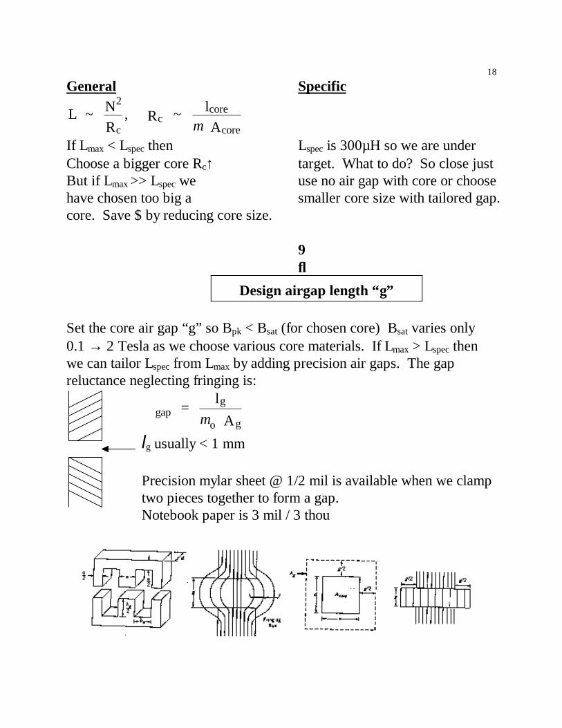
Design airgap length “g”
Set the core air gap “g” so Bpk < Bsat (for chosen core) Bsat varies only0.1 → 2 Tesla as we choose various core materials. If Lmax > Lspec thenwe can tailor Lspec from Lmax by adding precision air gaps. The gapreluctance neglecting fringing is:
gapg
o g =
l A
ℜ µlg usually < 1 mm
Precision mylar sheet @ 1/2 mil is available when we clamptwo pieces together to form a gap.Notebook paper is 3 mil / 3 thou

19
Double E core has Pbm of one big gap isthree distributed that B(fringe) from the core goes outair gaps -3 air gaps ⇒ further into copper windings increasing skinare better than one Why? effect and eddy current loss in the wires.
The effective air gap with an E core geometry is made in a cross-sectionand neglecting fringing.
Σ gaps = 3 * E core spacing ↓
The area of the gap Ag = Make 1/3 of size for less fringingAg (a+g)(d+g) gap size g << d,a - core sizesif flux extendsout additionalg/2 from core edge
Ag ≈ ad + g(a+d) + 0 second order terms
ℜ total = ℜ c(core) + ℜ gaps
↓ ↓ c
c c Al
µ
3g Ao gµ
Usually assume ℜ c is small compared to ℜ (air gap).We tailor 3 g to give desired Bpk(core) when Ipk is applied so that we donot exceed B(critical).NI = ℜ gφ
pk
c pk o g
NI
A B =
3g Aµ
Tune g for desired Bpk so Bpk < Bsat (core)

20
10↓
Set L to design value
if Lspec < Lmax We have two routes to reduce Lmax to reach Lspec.
L = N2
gℜ
We could increase ℜ g alone but this both reduces Bpk and Bac which is
good only for core loss. Since ℜ g =3g Ao gµ
by reducing Ag we could use
a smaller core, thereby reducing L and lowering core cost.
If we reduce N2 to reach Lspec from Lmax, then we save copper. But lowerN increases Bpk and hence core loss again we trade: “Cu” for “iron”.

21
Summary Start
B. Calculating Magnetic Core Loss
1. For Assumed Sinusoidal B(wt) Excitation
The total power loss including both hysteresis and eddy currents.

22
m 3 fe pk coreP W percm
= k (B ) f V
x y . Where Vcore = Aclc
The exponent “x” depends on how wide the hysteresis loop expandshorizontally (AH) as well as vertically (AB).
1.5 < X < 3.0; 2 is typical of practical core materials 1 < Y < 2; depending on core material
0 < Pm < 250 mWcm3
Bmax is the key parameter
PT = Pm * Vcore = PmAclc
Most PWM converter iL waveforms are square or triangle waves notsinusoids. These signals contain DC components. B(dc) causes no corelosses only core saturation! Harmonics of the switch frequency also occurfor many converter waveforms ⇒ Higher core losses due to the f2
dependence of eddy current losses.
2. Restraining Bpeak Values to below B(critical)We now consider voltages applied across the inductor, rather thancurrents driven through the inductor. Volt-sec balance will be constrained

23
by BSAT of the chosen core material as shown earlier.a. A soft B-H curveWith soft B-H curves L willdecrease slowly with current andnot change precipitously. OftenL(Bsat/2) = L((B=0)/2) for softsaturation cores
B
Bsat
HNiImax
However above Bsat µ → µo and L → short circuit or very small values
Then for B>BSAT we find L = µo c
c
A N 2
l where we replace µ(core) by
µ(air) and L is 1000 times smaller or so
b. B-H is also ∫vLdt vs iL
I
N wire turns
magneticcore
Vin
LLV = L di
dt
LLi =
V dtL
∫
N i = , = B AL c c c c cφ φℜFor Vin to the inductor being a sinusoid or any waveform the φ increasesto a peak only after integrating VL. A step of VL is easiest to visualize.
t
vLiL
φ
µ
= Ni
= N v dt
Nl
A
c2
c c
c
ℜ∫ L
Where ℜ c = lc
c cA Nµ 2

24
The flux varies as ∫v dtN
L
c ccAµ
l
φ v dtN
= BAc≈ ∫ L . Now Bpk occurs when iL and φ peaks.
pkc
1
cB =
vdtN A
= N A
∫ λ (volt-seconds)
The maximum Bpk occurs for when VL is either +VL for a long period oftime and the inductor current is ramping up to high values.
The VL and +VL square wave excitation vs. time causes atriangular Bpk waveform vs time.
t
vL
iL
+Bpk
2Bmax
-Bpk
maxc
B ( sec)2 N A
≡ −λ v
This integral dependence of B on VL says:
1. maxB ~ 1N
This relates the choice of wire turns to core issues.
It says for many wire turns Bmax ↓ while for one wire turn we achievemaximum B which must not exceed BSAT. Hence, it sets a minimumnumber of wire turns required.
2. maxc
B ~ 1
A This is sets up the need for larger size cores.
There are relations between the copper loss and core loss.3. N↑ Bmax ↓ reduces iron loss } Cu-Fe loss trading occurs
N ↑ increases I2R Cu loss } trade again!We then have to distinguish the cases of current through an inductor,amp-turn limits, and the case of voltage impressed across an inductor,

25
termed volt-sec limits. Each sets limits to inductor performance and insome cases they act in concert to limit inductor operation.
Summary of Saturation Design Rules:Rule Interpretation Ni < Bsatℜ A Amp-turn limit for an inductorWmax = ½Bsat
2lcoreAcore/µ Maximum energy that can be stored in a given core. Wmax = ½Bsat2Vgap/µo Maximum energy is determined by air gap volume if the core has high µ.Vo/N < wBsatA Maximum volts per turn (for a transformer) at frequency w.∫vdt < NBsatA Maximum volt-seconds for an inductor or transformer.