lecture 18 rlc circuits transformer maxwell electromagnetic waves
TRANSCRIPT
Lecture 18
RLC circuits Transformer Maxwell Electromagnetic Waves
Self-inductance Self-inductance occurs when the
changing flux through a circuit arises from the circuit itself
As the current increases, the magnetic flux through a loop due to this current also increases
The increasing flux induces an emf that opposes the change in magnetic flux
As the magnitude of the current increases, the rate of increase lessens and the induced emf decreases
This opposing emf results in a gradual increase of the current
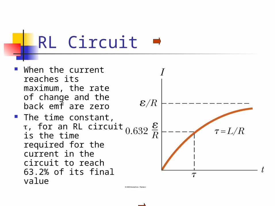
RL Circuit When the current
reaches its maximum, the rate of change and the back emf are zero
The time constant, , for an RL circuit is the time required for the current in the circuit to reach 63.2% of its final value
Energy Stored in a Magnetic Field The emf induced by an inductor
prevents a battery from establishing an instantaneous current in a circuit
The battery has to do work to produce a current This work can be thought of as energy
stored by the inductor in its magnetic field PEL = ½ L I2 Like ½ C V2

AC Circuit An AC circuit consists of a combination
of circuit elements and an AC generator or source
The output of an AC generator is sinusoidal and varies with time according to the following equation Δv = ΔVmax sin 2ƒt
Δv is the instantaneous voltage ΔVmax is the maximum voltage of the generator ƒ is the frequency at which the voltage changes,
in Hz
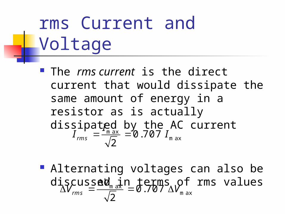
rms Current and Voltage The rms current is the direct current
that would dissipate the same amount of energy in a resistor as is actually dissipated by the AC current
Alternating voltages can also be discussed in terms of rms values
maxmax0.707
2rms
II I
maxmax0.707
2rms
VV V
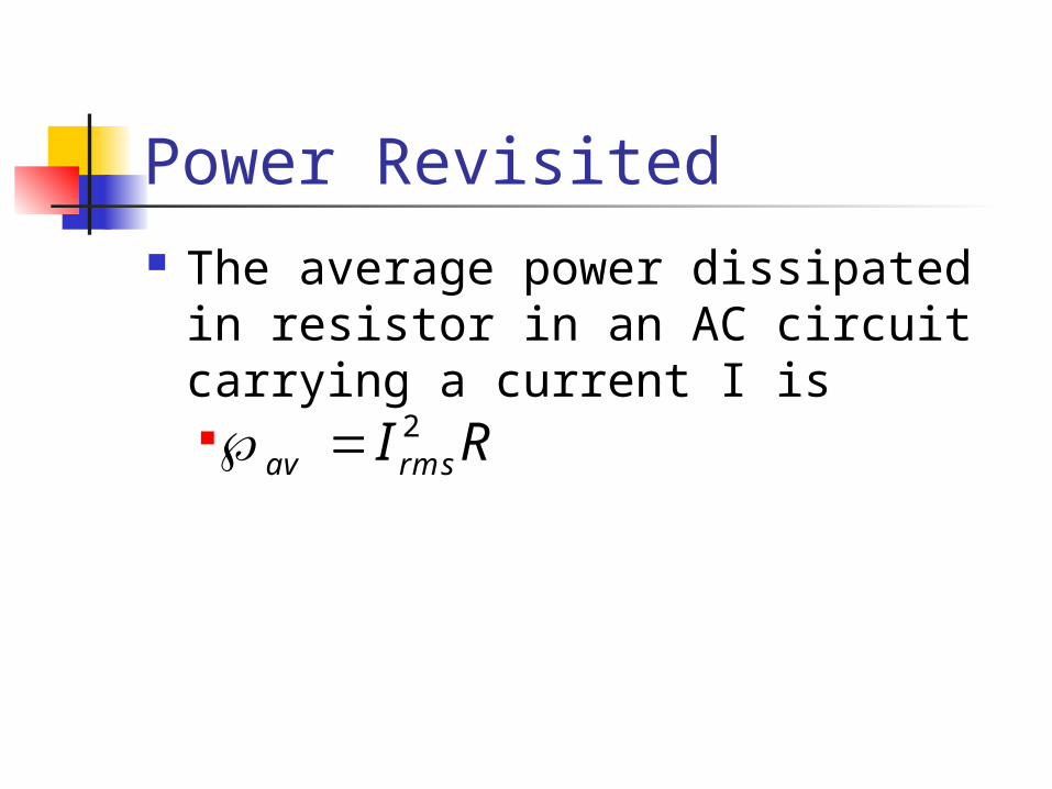
Power Revisited The average power dissipated in
resistor in an AC circuit carrying a current I is 2
av rmsI R
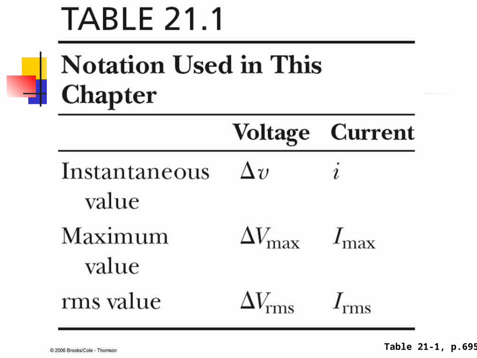
Table 21-1, p.695
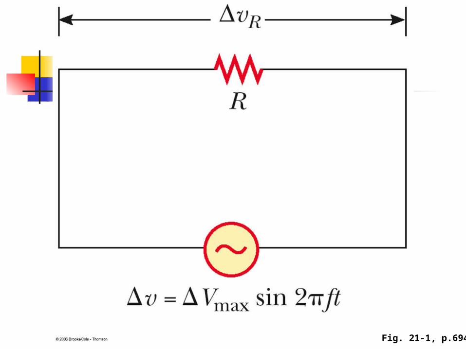
Fig. 21-1, p.694
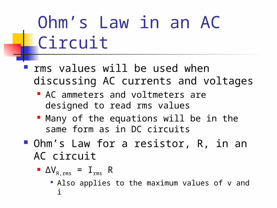
Ohm’s Law in an AC Circuit rms values will be used when discussing
AC currents and voltages AC ammeters and voltmeters are designed
to read rms values Many of the equations will be in the same
form as in DC circuits Ohm’s Law for a resistor, R, in an AC
circuit ΔVR,rms = Irms R
Also applies to the maximum values of v and i
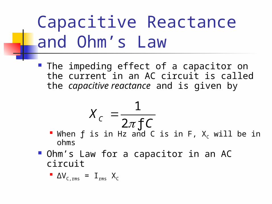
Capacitive Reactance and Ohm’s Law The impeding effect of a capacitor on the
current in an AC circuit is called the capacitive reactance and is given by
When ƒ is in Hz and C is in F, XC will be in ohms
Ohm’s Law for a capacitor in an AC circuit ΔVC,rms = Irms XC
12 ƒCX
C
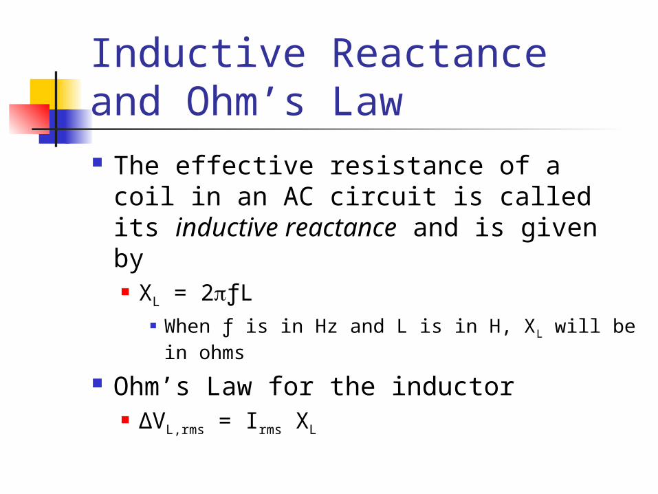
Inductive Reactance and Ohm’s Law The effective resistance of a coil in
an AC circuit is called its inductive reactance and is given by XL = 2ƒL
When ƒ is in Hz and L is in H, XL will be in ohms
Ohm’s Law for the inductor ΔVL,rms = Irms XL

The RLC Series Circuit The resistor,
inductor, and capacitor can be combined in a circuit
The current in the circuit is the same at any time and varies sinusoidally with time
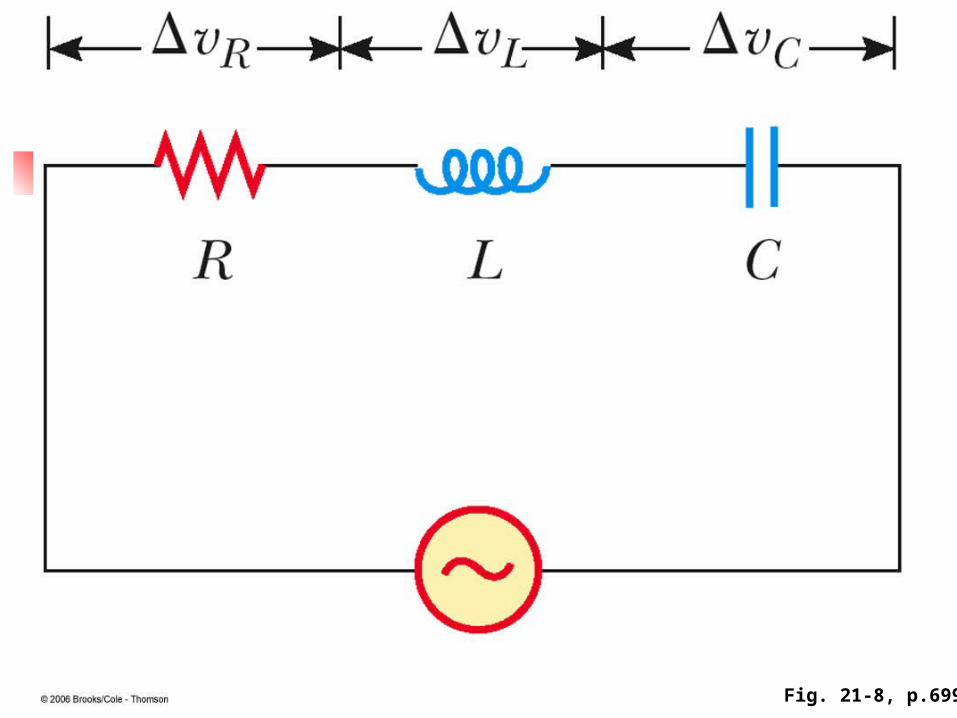
Fig. 21-8, p.699
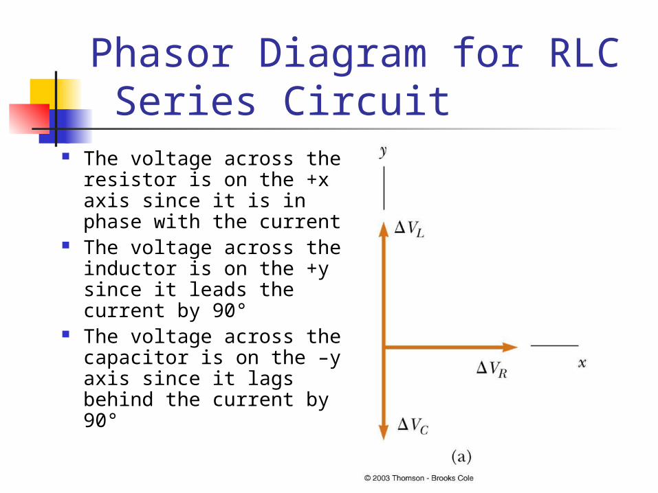
Phasor Diagram for RLC Series Circuit
The voltage across the resistor is on the +x axis since it is in phase with the current
The voltage across the inductor is on the +y since it leads the current by 90°
The voltage across the capacitor is on the –y axis since it lags behind the current by 90°
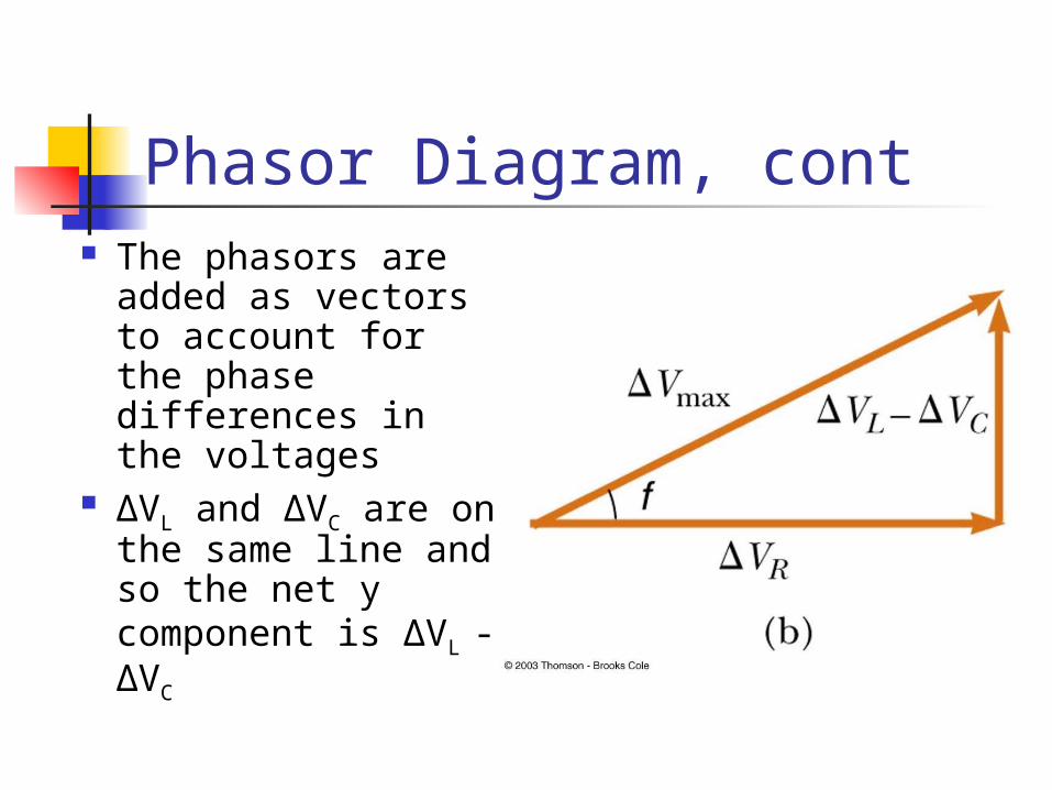
Phasor Diagram, cont The phasors are
added as vectors to account for the phase differences in the voltages
ΔVL and ΔVC are on the same line and so the net y component is ΔVL
- ΔVC
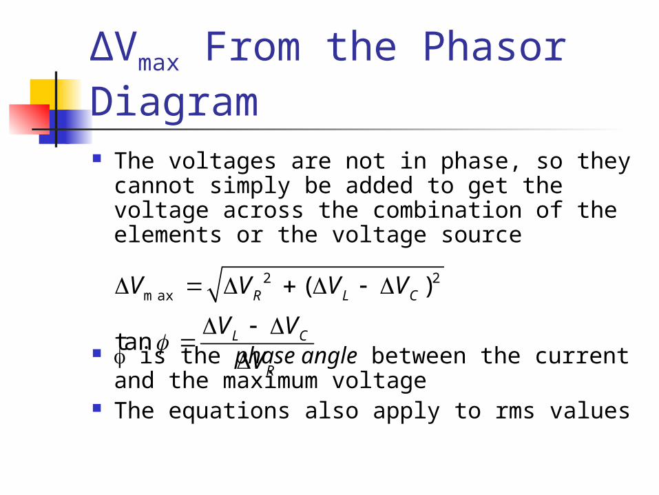
ΔVmax From the Phasor Diagram The voltages are not in phase, so they
cannot simply be added to get the voltage across the combination of the elements or the voltage source
is the phase angle between the current and the maximum voltage
The equations also apply to rms values
2 2max ( )
tan
R L C
L C
R
V V V V
V VV
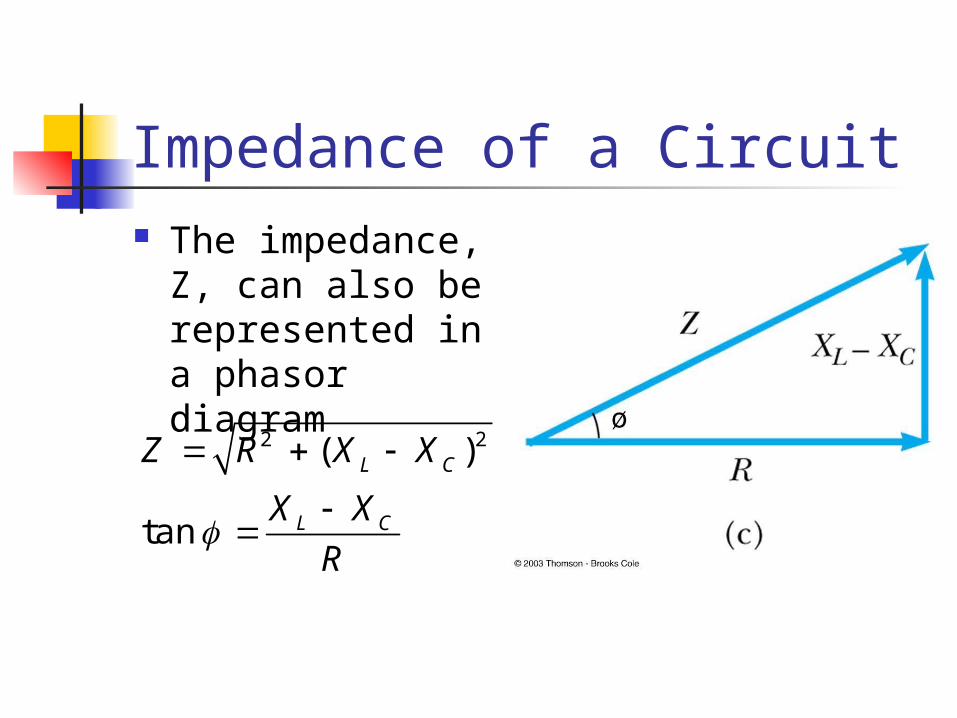
Impedance of a Circuit The impedance,
Z, can also be represented in a phasor diagram
2 2( )
tan
L C
L C
Z R X X
X XR

Fig. 21-11c, p.700
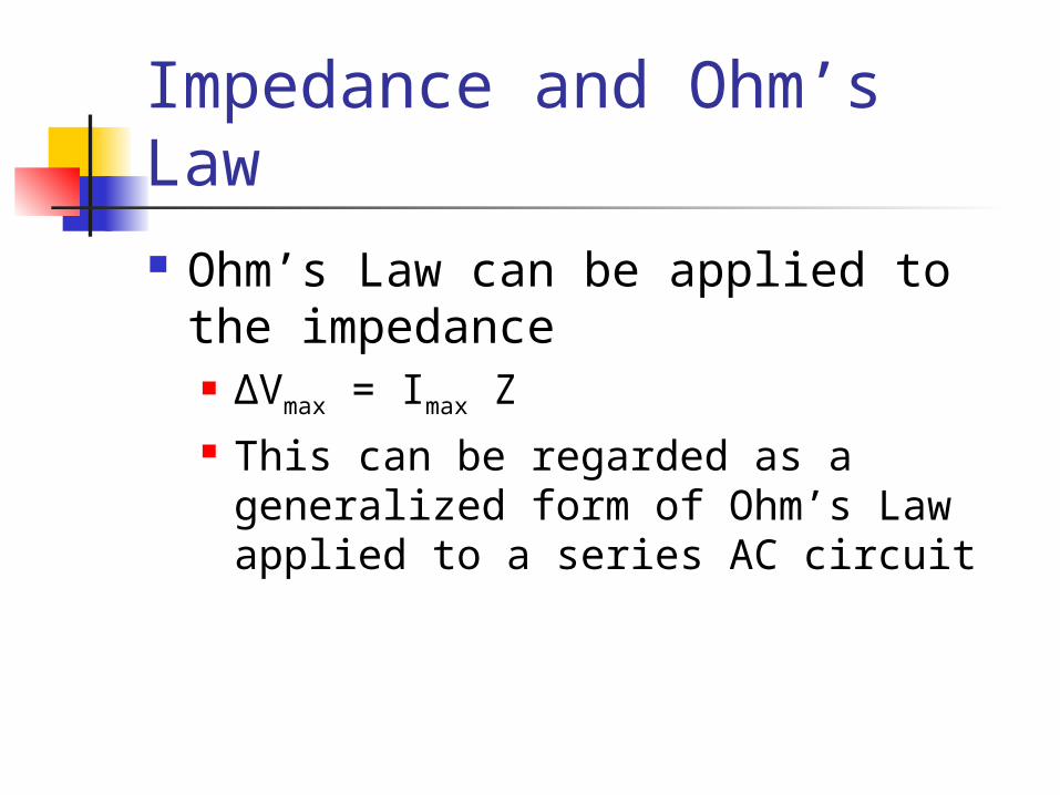
Impedance and Ohm’s Law Ohm’s Law can be applied to the
impedance ΔVmax = Imax Z This can be regarded as a generalized
form of Ohm’s Law applied to a series AC circuit
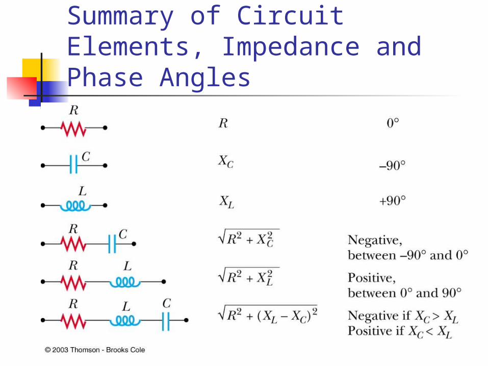
Summary of Circuit Elements, Impedance and Phase Angles
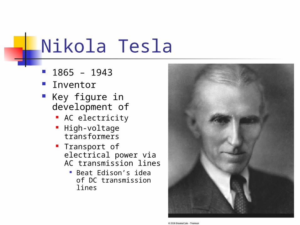
Nikola Tesla 1865 – 1943 Inventor Key figure in
development of AC electricity High-voltage
transformers Transport of electrical
power via AC transmission lines
Beat Edison’s idea of DC transmission lines
Problem Solving for AC Circuits Calculate as many unknown
quantities as possible For example, find XL and XC
Be careful of units – use F, H, Ω Apply Ohm’s Law to the portion of
the circuit that is of interest Determine all the unknowns asked
for in the problem
Power in an AC Circuit No power losses are associated with
pure capacitors and pure inductors in an AC circuit In a capacitor, during one-half of a cycle
energy is stored and during the other half the energy is returned to the circuit
In an inductor, the source does work against the back emf of the inductor and energy is stored in the inductor, but when the current begins to decrease in the circuit, the energy is returned to the circuit

Power in an AC Circuit, cont The average power delivered by
the generator is converted to internal energy in the resistor Pav = IrmsΔVR = IrmsΔVrms cos cos is called the power factor of the
circuit Phase shifts can be used to
maximize power outputs
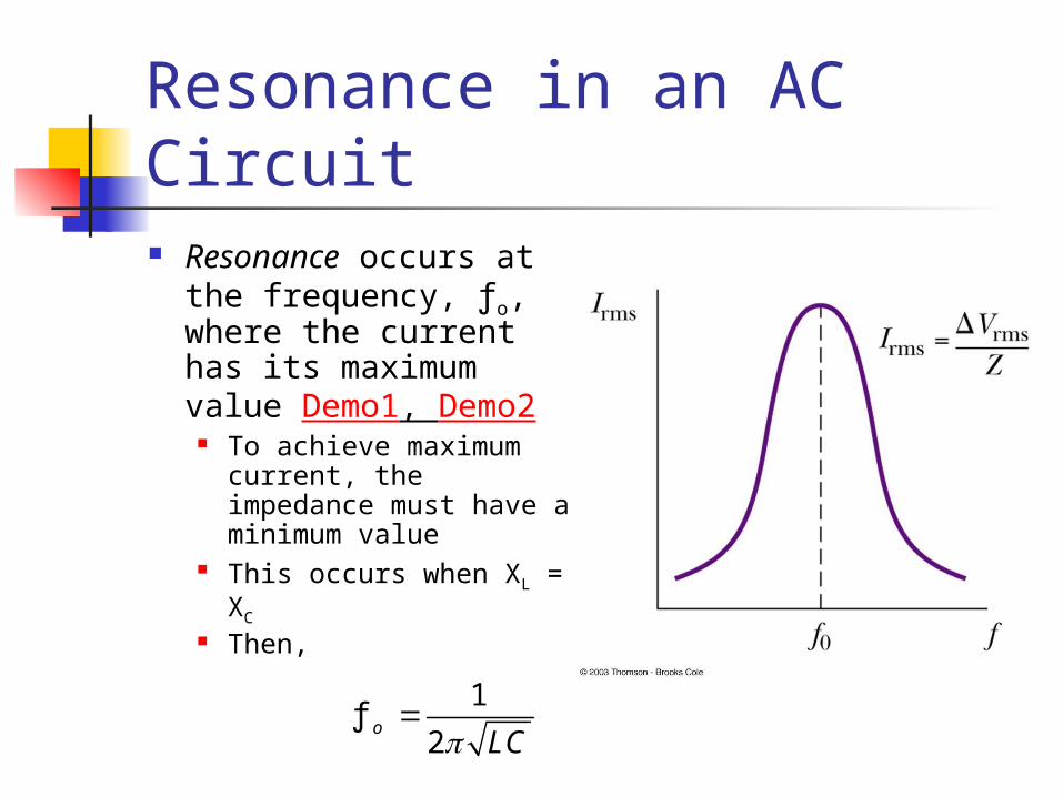
Resonance in an AC Circuit Resonance occurs at
the frequency, ƒo, where the current has its maximum value Demo1, Demo2
To achieve maximum current, the impedance must have a minimum value
This occurs when XL = XC
Then,
1ƒ
2o
LC

Fig. 21-14, p.704
Resonance, cont Theoretically, if R = 0 the current would be
infinite at resonance Real circuits always have some resistance
Tuning a radio A varying capacitor changes the resonance frequency of
the tuning circuit in your radio to match the station to be received
Metal Detector The portal is an inductor, and the frequency is set to a
condition with no metal present When metal is present, it changes the effective
inductance, which changes the current The change in current is detected and an alarm sounds
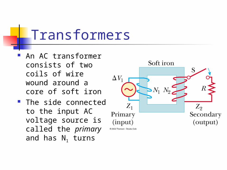
Transformers An AC transformer
consists of two coils of wire wound around a core of soft iron
The side connected to the input AC voltage source is called the primary and has N1 turns
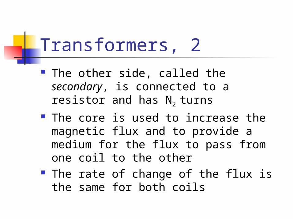
Transformers, 2 The other side, called the secondary, is
connected to a resistor and has N2 turns
The core is used to increase the magnetic flux and to provide a medium for the flux to pass from one coil to the other
The rate of change of the flux is the same for both coils
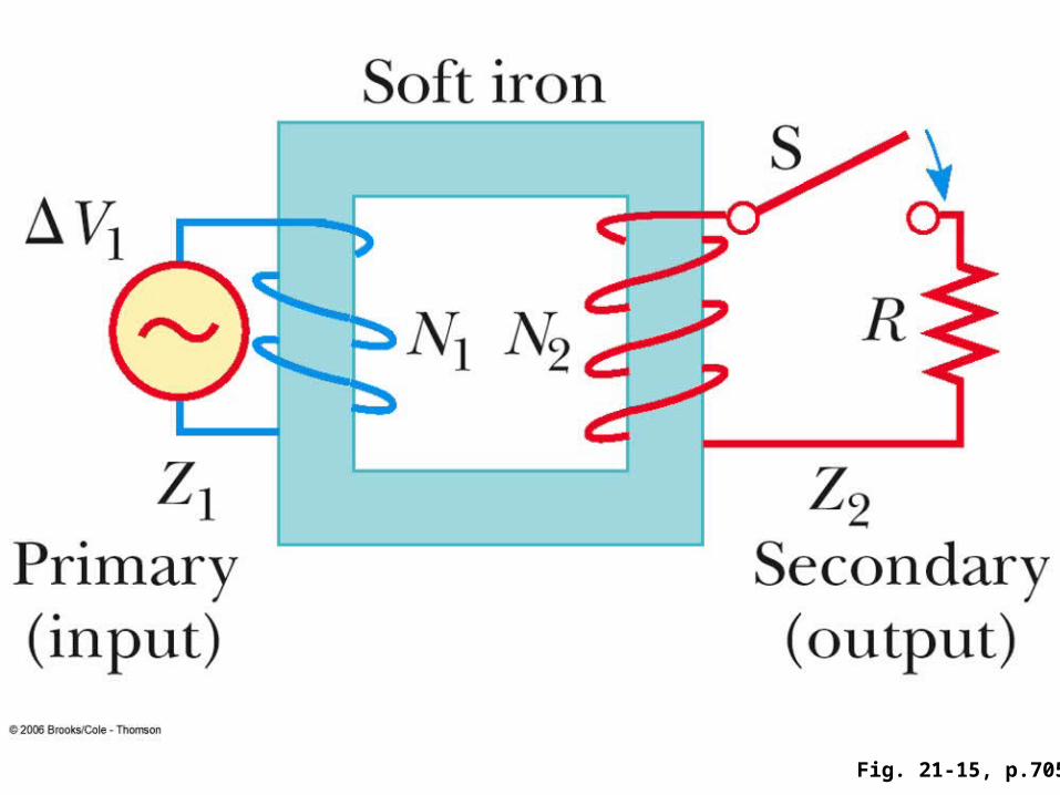
Fig. 21-15, p.705
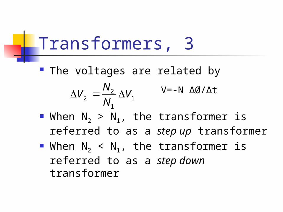
Transformers, 3 The voltages are related by
When N2 > N1, the transformer is referred to as a step up transformer
When N2 < N1, the transformer is referred to as a step down transformer
22 1
1
NV V
N V=-N ΔØ/Δt
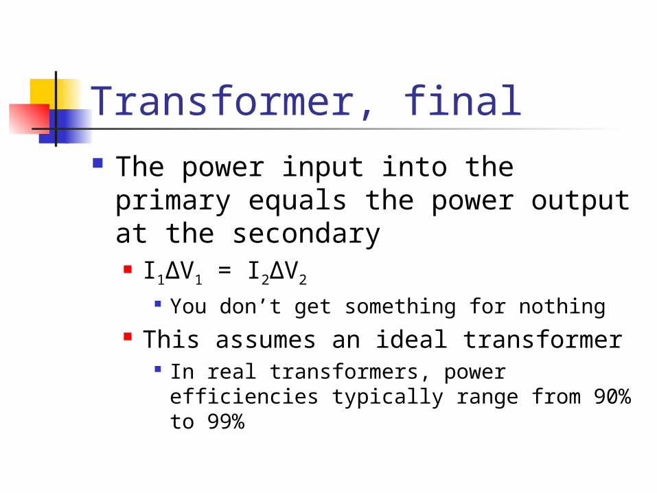
Transformer, final The power input into the primary
equals the power output at the secondary I1ΔV1 = I2ΔV2
You don’t get something for nothing This assumes an ideal transformer
In real transformers, power efficiencies typically range from 90% to 99%
Electrical Power Transmission When transmitting electric power over
long distances, it is most economical to use high voltage and low current Minimizes I2R power losses
In practice, voltage is stepped up to about 230 000 V at the generating station and stepped down to 20 000 V at the distribution station and finally to 120 V at the customer’s utility pole
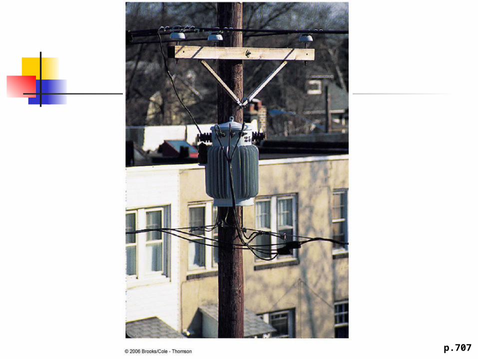
p.707

James Clerk Maxwell 1831 – 1879 Electricity and
magnetism were originally thought to be unrelated
in 1865, James Clerk Maxwell provided a mathematical theory that showed a close relationship between all electric and magnetic phenomena
More of Maxwell’s Contributions Electromagnetic theory of light Kinetic theory of gases Nature of Saturn’s rings Color vision Electromagnetic field
interpretation Led to Maxwell’s Equations

Maxwell’s Starting Points Electric field lines originate on positive
charges and terminate on negative charges Magnetic field lines always form closed
loops – they do not begin or end anywhere A varying magnetic field induces an emf
and hence an electric field (Faraday’s Law) Magnetic fields are generated by moving
charges or currents (Ampère’s Law)
Maxwell’s Predictions Maxwell used these starting points and a
corresponding mathematical framework to prove that electric and magnetic fields play symmetric roles in nature
He hypothesized that a changing electric field would produce a magnetic field
Maxwell calculated the speed of light to be 3x10⁸ m/s
He concluded that visible light and all other electromagnetic waves consist of fluctuating electric and magnetic fields, with each varying field inducing the other
Hertz’s Confirmation of Maxwell’s Predictions 1857 – 1894 First to generate and
detect electromagnetic waves in a laboratory setting
Showed radio waves could be reflected, refracted and diffracted
The unit Hz is named for him
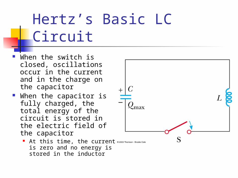
Hertz’s Basic LC Circuit When the switch is
closed, oscillations occur in the current and in the charge on the capacitor
When the capacitor is fully charged, the total energy of the circuit is stored in the electric field of the capacitor
At this time, the current is zero and no energy is stored in the inductor

LC Circuit, cont As the capacitor discharges, the energy stored in
the electric field decreases At the same time, the current increases and the
energy stored in the magnetic field increases When the capacitor is fully discharged, there is
no energy stored in its electric field The current is at a maximum and all the energy is
stored in the magnetic field in the inductor The process repeats in the opposite direction There is a continuous transfer of energy between
the inductor and the capacitor
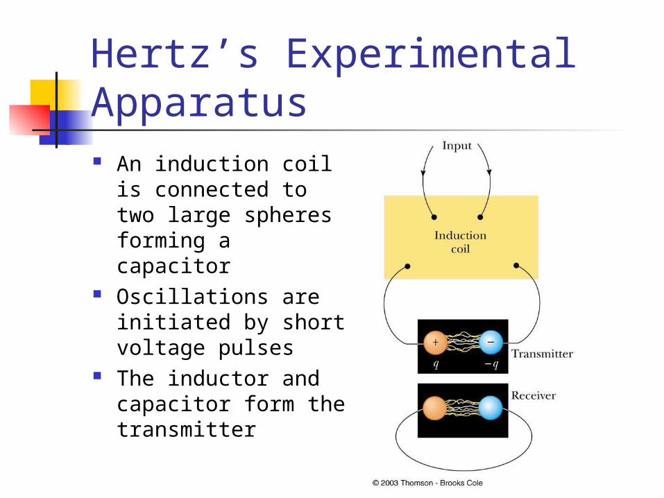
Hertz’s Experimental Apparatus An induction coil is
connected to two large spheres forming a capacitor
Oscillations are initiated by short voltage pulses
The inductor and capacitor form the transmitter
Hertz’s Experiment Several meters away from the
transmitter is the receiver This consisted of a single loop of wire
connected to two spheres It had its own inductance and capacitance
When the resonance frequencies of the transmitter and receiver matched, energy transfer occurred between them
Hertz’s Conclusions Hertz hypothesized the energy transfer
was in the form of waves These are now known to be electromagnetic
waves Hertz confirmed Maxwell’s theory by
showing the waves existed and had all the properties of light waves They had different frequencies and
wavelengths

Hertz’s Measure of the Speed of the Waves Hertz measured the speed of the waves
from the transmitter He used the waves to form an interference
pattern and calculated the wavelength From v = f λ, v was found v was very close to 3 x 10⁸ m/s, the known
speed of light This provided evidence in support of
Maxwell’s theory