lecture 11 jan-30-13 - mehrpouyan 11 jan-30-13.pdfsignal constellation the combination of all the...
TRANSCRIPT

Signals and Systems
1
California State University, Bakersfield
Hani Mehrpouyan1,
Department of Electrical and Computer Engineering,
California State University, Bakersfield
Lecture 11 (Signal Space Representation)
January 30th, 2013
1 Some of the lectures notes here reproduced are taken from course textbooks: “Digital Communications: Fundamentals and Applications” B. Sklar. “Communication Systems Engineering”, J. G. Proakis and M Salehi, and “Lecture Notes for Digital Communication, Queen’s University, Canada”, S. Yousefi.

Signals and Systems
2
California State University, Bakersfield
Outline
� Signal Space Representation
� Signal Constellation
� Operations
� Digital Modulations

Signals and Systems
3
California State University, Bakersfield
Signal Space Representations

Signals and Systems
4
California State University, Bakersfield
Signal Constellation
� The combination of all the N-D Euclidean points/vectors obtained from the waveforms (in the underlying N-D Euclidean space RN) is referred to as a signal constellation.
� This provides an elegant geometrical representation of our DCS (Reminder: MODEM or brain of the system= digital signal set/bag).
� Many waveform operations can be done easier in the signal constellation, i.e., in terms of the geometrical or Euclidean representation.
� Note the Similarity with other transformations such as Fourier transform.

Signals and Systems
5
California State University, Bakersfield
Operations� We discuss the equivalence of operations in the signal space
and the corresponding vector space now.
� Using the representation of signals in terms of the basis functions found (e.g., using GSOM), each signal is mapped uniquely to an N-D vector (N is the dimensionality of the signal constellation).
� Equivalence of operations in signal space and the vector space (for real signals):

Signals and Systems
6
California State University, Bakersfield
Operations
Signals and Systems
7
California State University, Bakersfield
Operations
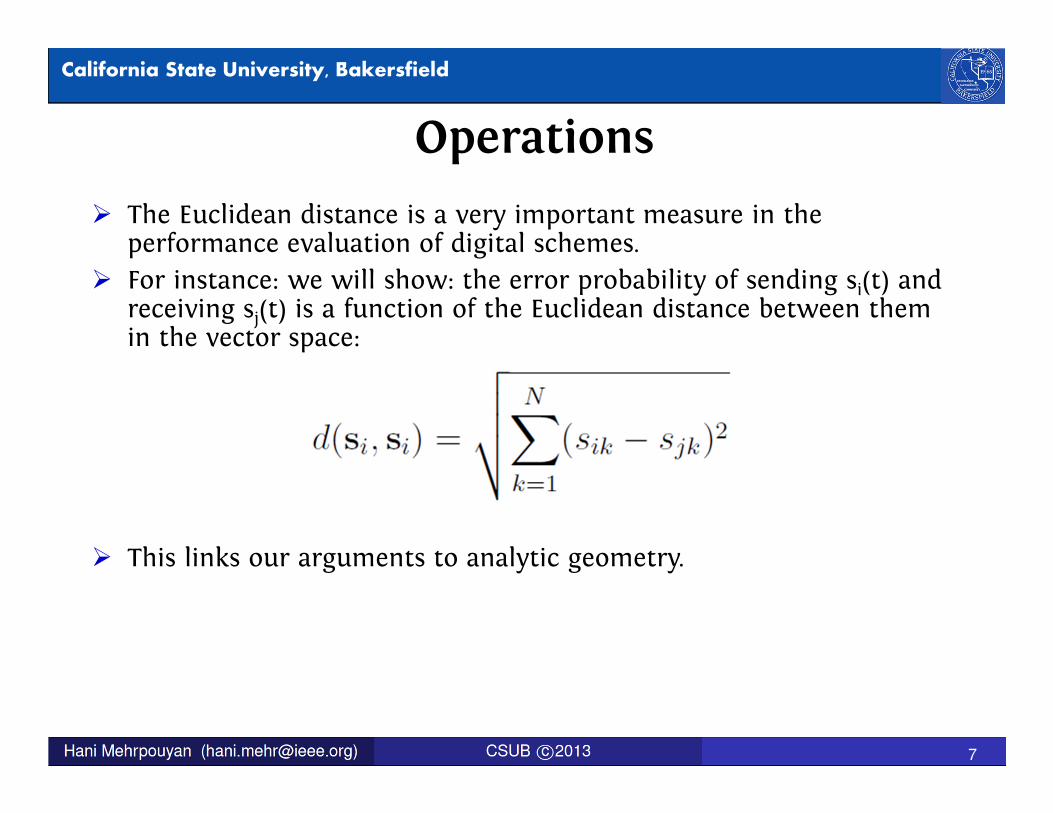
� The Euclidean distance is a very important measure in the performance evaluation of digital schemes.
� For instance: we will show: the error probability of sending si(t) and receiving sj(t) is a function of the Euclidean distance between them in the vector space:
� This links our arguments to analytic geometry.

Signals and Systems
8
California State University, Bakersfield
Digital Modulation Schemes
�In what follows, unless otherwise specified, we will assume that the output of the source of information (with the aid of an encoder or compressor) is an independent and identically distributed (i.i.d.) Bernoulli/binary process.
�If the source coder is ideal (perfect compression), then the Bernoulli source at hand will be uniform: probabilities of 0’s and 1’s are equal (equiprobable sequence).

Signals and Systems
9
California State University, Bakersfield
Pulse Amplitude Modulation (PAM)� Modulate the information on a sequence of pulses by varying
the amplitudes.
� Binary PAM (BPAM): the simplest digital modulation scheme: represent 0 and 1 by −A and A amplitudes (e.g., voltage levels):
� where the symbol interval Ts is simply equal to the bit interval Tb (seconds).

Signals and Systems
10
California State University, Bakersfield
Pulse Amplitude Modulation (PAM)

Signals and Systems
11
California State University, Bakersfield
PAM
� Note: B-PAM is also referred to as binary antipodal signaling.
� Practical perspective: Here the base signal or pulse shape is a rectangular pulse. Is this a good choice? why? Think of band-width, ISI, and, feasibility (rise time and decay/fall time).
� In general for a digital bag/scheme with M signals, we need k = logbM bits (of the source) to label or represent each signal:
� Symbol interval: Ts = k · Tb (both measured in seconds).
� Symbol rate: Rs = 1/Ts= 1/(k·Tb)= Rb/k. Rb is the bit rate in bits per second (bps) and Rs is the symbol rate or the so-called baud rate in symbol per second (sps).
� Obviously: we would like M = 2k to be a power of 2 (viz., k be an integer).

Signals and Systems
12
California State University, Bakersfield
PAM� M-ary PAM or M-PAM: Example: in 4-PAM every 2 bits
(every dibit) from the source will be mapped to a signal according to the following mapping:

Signals and Systems
13
California State University, Bakersfield
PAM� Given the above 4 signals, think of the number of ways one can
label them with bits.
� It is important to find out if there are differences in term of performance among different labelings/mappings.
� In practice, one can use any feasible pulse shape gT(t) on the [0, T] interval (where T is the required symbol interval) with desirable spectrum and ISI, e.g., Raised cosine pulse.
� We will discuss this later. This is an important issue in the baseband communication.
� As discussed before, an important parameter in any DCS is the average power needed for the communication.
� Average power is intimately related to the average energy spent on the modulation scheme.

Signals and Systems
14
California State University, Bakersfield
PAM

Signals and Systems
15
California State University, Bakersfield
Bandpass signaling� For baseband, there is not much more to what we already
discussed in terms of the modulation. Yet, for bandpass, we still need to do the heterodyning (frequency shifting).
� The baseband PAM signal discussed with a low pass base pulse gT(t) can be made a bandpass signal through mixing:

Signals and Systems
16
California State University, Bakersfield
Bandpass signaling� which, in the terminology of analog communications, is a
Double-Side-Band Suppressed-Carrier (DSB-SC) type of signal.
� If the baseband signals and gT(t) have a Bandwidth (BW) of W Hz then the above bandpass PAM signal will have a BW of 2W Hz.