lecture 11 etching techniques reading: chapter...
TRANSCRIPT

ECE 6450 - Dr. Alan DoolittleGeorgia Tech
Lecture 11
Etching Techniques
Reading:
Chapter 11

ECE 6450 - Dr. Alan DoolittleGeorgia Tech
Characterized by:
1.) Etch rate (A/minute)
2.) Selectivity: S=etch rate material 1 / etch rate material 2 is said to have a selectivity of “S” for material 1 over material 2.
RateEtch VerticalRateEtch Lateral1A
3.) Anisotropy:
4.) Under cut: If 0.8 um lines result from an etch using 1 um photoresist lines as a mask, it is said that the process bias is 0.1 um for that particular etch.
Etching Techniques

ECE 6450 - Dr. Alan DoolittleGeorgia Tech
Wet
Che
mic
al
General Increasing Anisotropy*
* Some wet and plasma chemistries can have high anisotropy by using the chemistry to etch preferred crystalline planes.
Increasing Mean Free PathAnisotropy can depend on mean free path, or on DC plasma bias.
•Increasing mean free path (generally) increases anisotropy
•Increasing DC bias (generally) increases anisotropy
Controlling Anisotropy

ECE 6450 - Dr. Alan DoolittleGeorgia Tech
Etching can be characterized by how much of the process is:Chemical: Using the chemistry of the etch to remove material into a solution (liquid or gaseous solution)Sputtering: In plasma systems, Ions can be accelerated fast enough so as to “Ram” into the surface, “knocking out” atoms/molecules
Many etching techniques use both chemical and sputtering.
1.) Wet Chemical Etching:Advantages: Cheap, almost no damage due to purely chemical nature, highly selectiveDisadvantages: poor anisotropy, poor process control (temperature sensitivity), poor particle control, high chemical disposal costs, difficult to use with small features (bubbles, etc...).
Advantages Common to all of the following: Low chemical disposal, temperature insensitivity, near instant start/stop (no drips, etc..), applicable to small features (gas permeation of small features).
2.) Plasma Etching:Advantages: Moderately anisotropic using sidewall polymerization techniques (discussed later) , can be selectiveDisadvantages: Ion damage, residue
3.) Reactive Ion Etching:Advantages: Highly anisotropic using sidewall polymerization techniques, can be selective but less so than plasma etching due higher DC bias and longer mean free path.Disadvantages: High ion damage, residue
4.) Ion Milling:Advantages: Extremely anisotropic, Independent of material composition (useful in quaternaries).Disadvantages: Extremely high ion damage, non-selective, residue
Common Etching Techniques

ECE 6450 - Dr. Alan DoolittleGeorgia Tech
Process requires:1.) Movement of etchant species toward the wafer surface2.) Reaction at the surface3.) Movement of reactant products away from the surfaceAny one of the above three steps can be the etch rate limiting step
2 important Wet Etch Concepts:A.) Buffering the solution to maintain constant etch rate with time:Consider etching of SiO2
OHSiFHHFSiO 2622 26 But as the HF is depleted (used up) from the solution the etch rate would change. Thus, a Buffering solution is added that controls the HF concentration as:
HFNHFNH 34
The HF concentration remains “saturated”. As HF is consumed etching SiO2, the above reaction replaces the HF, keeping the etch rate constant.
Wet Chemical Etching:
ECE 6450 - Dr. Alan DoolittleGeorgia Tech
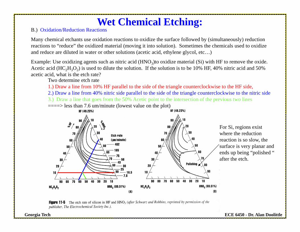
Wet Chemical Etching:B.) Oxidation/Reduction Reactions
Many chemical etchants use oxidation reactions to oxidize the surface followed by (simultaneously) reduction reactions to “reduce” the oxidized material (moving it into solution). Sometimes the chemicals used to oxidize and reduce are diluted in water or other solutions (acetic acid, ethylene glycol, etc…)
Example: Use oxidizing agents such as nitric acid (HNO3)to oxidize material (Si) with HF to remove the oxide. Acetic acid (HC2H3O2) is used to dilute the solution. If the solution is to be 10% HF, 40% nitric acid and 50% acetic acid, what is the etch rate?
Two determine etch rate1.) Draw a line from 10% HF parallel to the side of the triangle counterclockwise to the HF side,2.) Draw a line from 40% nitric side parallel to the side of the triangle counterclockwise to the nitric side3.) Draw a line that goes from the 50% Acetic point to the intersection of the previous two lines====> less than 7.6 um/minute (lowest value on the plot)
For Si, regions exist where the reduction reaction is so slow, the surface is very planar and ends up being “polished “ after the etch.
ECE 6450 - Dr. Alan DoolittleGeorgia Tech
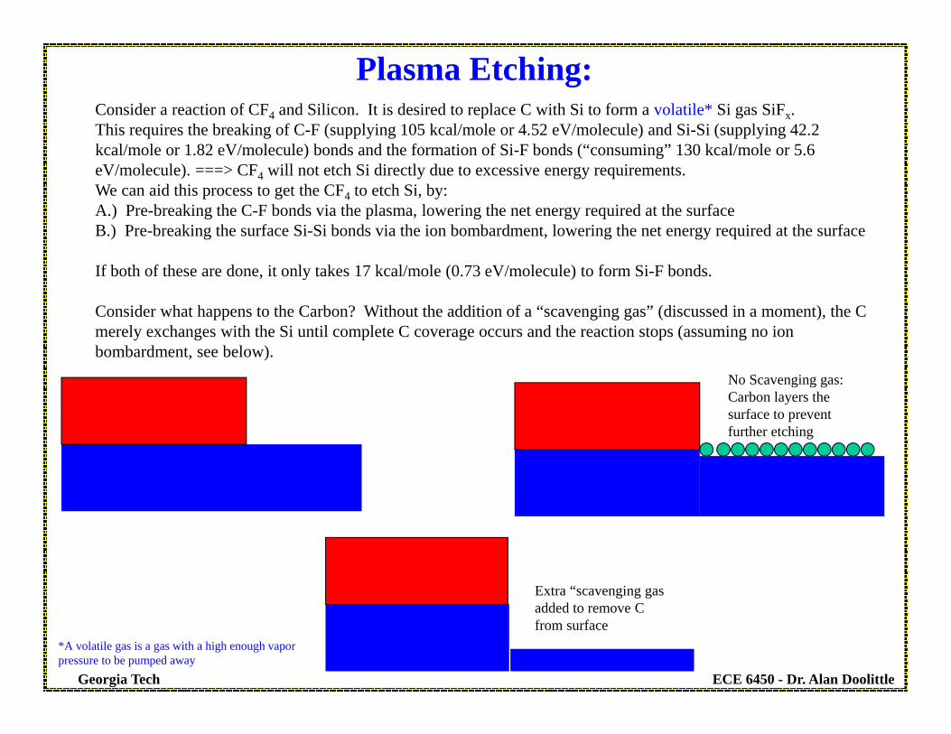
Plasma Etching:Consider a reaction of CF4 and Silicon. It is desired to replace C with Si to form a volatile* Si gas SiFx.This requires the breaking of C-F (supplying 105 kcal/mole or 4.52 eV/molecule) and Si-Si (supplying 42.2 kcal/mole or 1.82 eV/molecule) bonds and the formation of Si-F bonds (“consuming” 130 kcal/mole or 5.6 eV/molecule). ===> CF4 will not etch Si directly due to excessive energy requirements.We can aid this process to get the CF4 to etch Si, by:A.) Pre-breaking the C-F bonds via the plasma, lowering the net energy required at the surfaceB.) Pre-breaking the surface Si-Si bonds via the ion bombardment, lowering the net energy required at the surface
If both of these are done, it only takes 17 kcal/mole (0.73 eV/molecule) to form Si-F bonds.
Consider what happens to the Carbon? Without the addition of a “scavenging gas” (discussed in a moment), the C merely exchanges with the Si until complete C coverage occurs and the reaction stops (assuming no ion bombardment, see below).
No Scavenging gas: Carbon layers the surface to prevent further etching
Extra “scavenging gas added to remove C from surface
*A volatile gas is a gas with a high enough vapor pressure to be pumped away

ECE 6450 - Dr. Alan DoolittleGeorgia Tech
Plasma Etching:Tailoring gas Chemistry for Selectivity vs Anisotropy:Consider the addition of oxygen (O2) to the plasma:C can be removed by forming CO and CO2 gases which are easily pumped away (higher vapor pressure than solid C or CFx gas). This decreases the amount of C available to form CFx radicals, increasing the relative F concentration in the plasma, increasing the etch rate. However, the oxygen can create SiO2 on the surface which etches slower in the CF4 chemistry. Si etch rates peak at about 12% O2 due to formation of SiO2 on the surface at high oxygen levels. Adding small amounts of O2 increases the Si over SiO2 selectivity at the expense of anisotropy.

ECE 6450 - Dr. Alan DoolittleGeorgia Tech
Plasma Etching:Tailoring gas Chemistry for Selectivity vs Anisotropy:
Polymerization:
By adding hydrogen to the plasma, the fluorine content of the plasma is scavenged* (F+H->HF where HF has a higher vapor pressure and thus, is pumped away faster) and CFX forms. This fluorocarbon residue, CFX, can be deposited preferentially on the sidewalls, enhancing anisotropy by forming a lateral etch mask. These fluorocarbons are not easily removed by the plasma chemistry, and thus, must be “sputtered” by ion bombardment. Since the E-field is perpendicular to the wafer surface, minimal fluorocarbon etching of sidewalls occurs while deposition on the flat portions of the wafer are easily removed.
In terms of gas chemistry, adding H2 does the opposite of adding O2. Adding small amounts of H2 increases SiO2etch anisotropy.
Scavenged: When a gas is introduced to intentionally remove another species (gas or solid compound) this introduced gas is called a scavenging gas.

ECE 6450 - Dr. Alan DoolittleGeorgia Tech
Problems experienced in practice:

ECE 6450 - Dr. Alan DoolittleGeorgia Tech
Material = Si Condition Etch Rate Anisotropy Selectivity Si over SiO2
F-Rich (O2 added) Increased Decreased Increased
C-Rich Decreased Increased Decreased
Material = SiO2 Condition Etch Rate Anisotropy Selectivity SiO2 over Si
F-Rich Increased Decreased Decreased
C-Rich (H2 added)Decreased (only slightly since HF
etches SiO2)Increased Unchanged
Summary of Plasma Etch Chemistry using CF4 to etch Si
Effect of reactor loadingDepletion of the reactant gas by increased surface area is sometimes a problem. (Lab conditions and multi-wafer systems). The etch rate can be determined as,
where Ro is the empty chamber etch rate, A is area of wafers loading into the reactor, and k is constant that can be reduced by increasing gas flows at constant pressure
kARoR
1

ECE 6450 - Dr. Alan DoolittleGeorgia Tech
Emission Spectroscopy: Observing the intensity of individual plasma lines resulting from molecular recombination events. These events can be very weak so sensitive equipment is required.
Interferometry: Requires large unpatterned areas.
Plasma Process Monitoring
Reactive Ion EtchingDesigned to give better control of Selectivity and Anisotropy independently:
Characteristics:
1.) Lower operating pressures result in higher anisotropy (longer mean free path allows more directed acceleration of ions)
2.) A DC bias enhances ion bombardment energy, resulting in some sputtering and chemical catalyst effect.
3.) A sidewall polymerization gas (BCl3, CCl4 etc...) is added to enhance anisotropy. The enhanced sputtering features of RIE insure “mostly” or “only” sidewall polymerization.
More damage occurs: Many III-V processes can not tolerate this damage.
Some unintentional deposition of the polymerization gas can result in defects if conditions are not optimized.