lecture 11 ch. 11 critically stressed faults and fluid
TRANSCRIPT
Lecture 11
Ch. 11 Critically stressed faults and fluid flow (18, 20 May 2020)
Ki-Bok Min, PhD
Professor
Department of Energy Resources Engineering
Seoul National University
Reservoir Geomechanics, Fall, 2020

Disclaimer
• Materials in these slides cannot be used without the written consent from the instructor

Critically stressed faults and fluid flowImportance
• Critically stressed faults and fluid flow
– Fractures are often main conduits for fluid flow in low-permeable formations
• Importance of stress analysis in fault in relation to in situ stress
– In situ stress constraints
– Fluid flow analysis – oil and gas
– Hydraulic stimulation – shear stimulation for shale gas and geothermal
– Earthquake analysis
• Topics
– Influence of fracture and faults on reservoir permeability
– Geomechanical control on fault sealing and leakage in fault bounded reservoir
– Dynamic constraints on hydrocarbon column heights and reservoir pressure in fault bounded reservoir
We may go beyond the interpretations based on structural closure

Chapter 4. Rock Failure in compression, tension and shear
• In situ stress constraints

Fractured reservoirs and fluid flowCritically stressed fault – Stress polygon
• Hypothesis of ‘critically stressed fault’ can be applied to constrain the range of in situ stress
– Stress polygon help to draw the range of in situ stress
– Stress state above the line of SHmax = Shmin
Zoback MD, 2007, Reservoir Geomechanics, Cambridge University Press

• In situ stress measurement
• Byerlee’s law seems to work
• Earth crust appears to be in a state of (failure) equilibrium
Fractured reservoirs and fluid flowCritically stressed fault – observations
Zoback MD, 2007, Reservoir Geomechanics, Cambridge University Press

Fractured reservoirs and fluid flowCritically stressed fault
• Identifying active faults is important both hydraulically & mechanically
• “faults that are mechanically alive are hydraulically alive and faults that are mechanically dead are hydraulically dead”
Fractures with varying orientations are under various
combinations of normal stress + shear stress
Permeable faults and impermeable faults plotted with
respect to failure criterion and stress condition (Cajon Pass
scientific borehole near the San Andreas fault)Zoback MD, 2007, Reservoir Geomechanics, Cambridge University Press
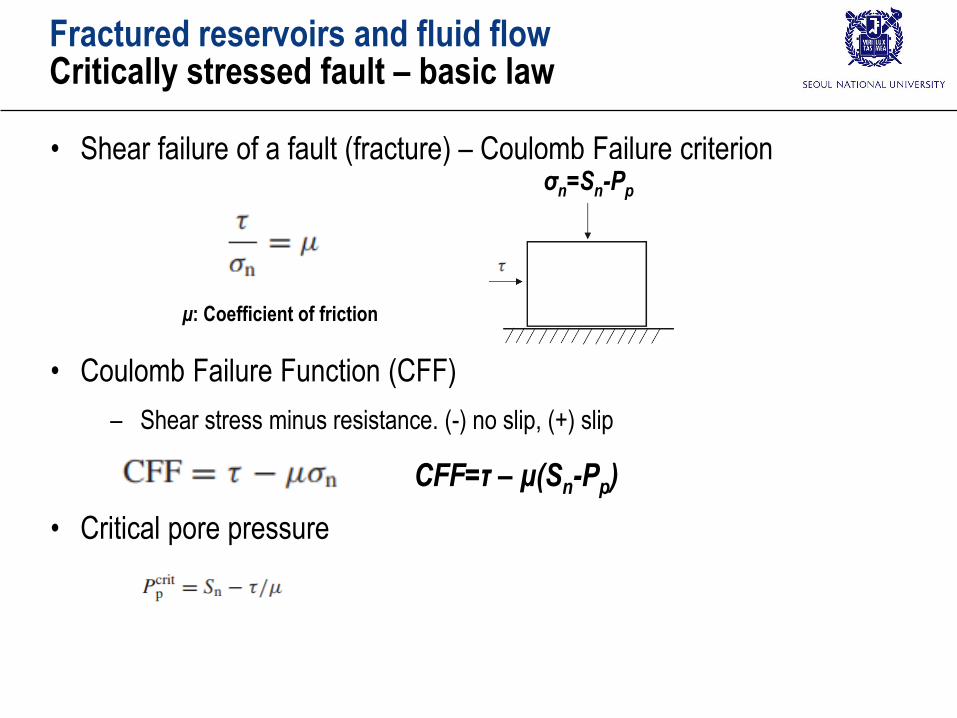
Fractured reservoirs and fluid flowCritically stressed fault – basic law
• Shear failure of a fault (fracture) – Coulomb Failure criterion
• Coulomb Failure Function (CFF)
– Shear stress minus resistance. (-) no slip, (+) slip
• Critical pore pressure
σn=Sn-Pp
μ: Coefficient of friction
CFF=τ – μ(Sn-Pp)
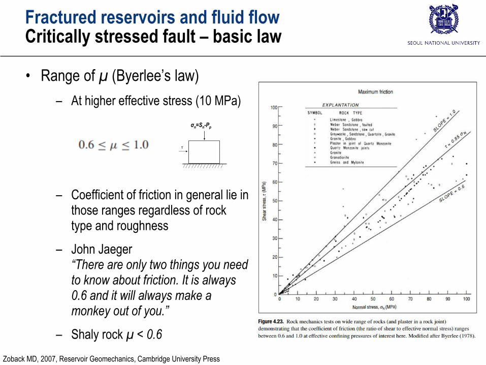
Fractured reservoirs and fluid flowCritically stressed fault – basic law
• Range of μ (Byerlee’s law)
– At higher effective stress (10 MPa)
– Coefficient of friction in general lie in those ranges regardless of rock type and roughness
– John Jaeger “There are only two things you need to know about friction. It is always 0.6 and it will always make a monkey out of you.”
– Shaly rock μ < 0.6
σn=Sn-Pp
Zoback MD, 2007, Reservoir Geomechanics, Cambridge University Press

• Normal mechanical behavior
– Unit: Stress/length (MPa/m)
– Linear model
– Non-linear model
• Shear mechanical behavior
– Unit: Stress/length (MPa/m)
– Linear model
– Non-linear model: e.g., Barton’s equation
– Dilation angle
Fractured reservoirs and fluid flowCritically stressed fault – mechanical behavior
nn
nc d
s s sK
n n nK
1 normal dilationtan
shear displacementdilation
Rothert & Baisch (2010)
Rothert E & Baisch S, 2010, Passive Seismic Monitoring: Mapping Enhanced Fracture Permeability, 10th World Geothermal Congress, Paper No.3161
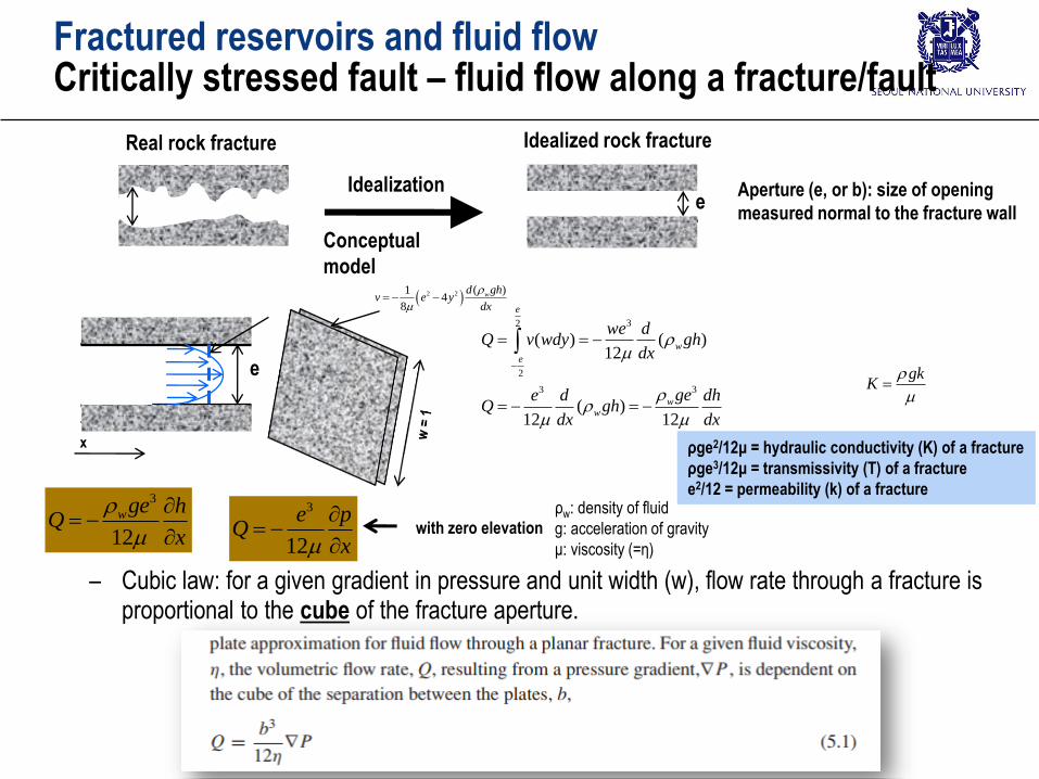
Fractured reservoirs and fluid flowCritically stressed fault – fluid flow along a fracture/fault
e
Real rock fracture Idealized rock fracture
Idealization
Conceptual
model
Aperture (e, or b): size of opening
measured normal to the fracture wall
– Cubic law: for a given gradient in pressure and unit width (w), flow rate through a fracture is proportional to the cube of the fracture aperture.
e
x
3
12
wge hQ
x
3
12
e pQ
x
with zero elevation
ρw: density of fluid
g: acceleration of gravity
μ: viscosity (=η)
32
2
33
( ) ( )12
( )12 12
e
w
e
ww
we dQ v wdy gh
dx
gee d dhQ gh
dx dx
2 2 ( )14
8
wd ghv e y
dx
ρge2/12μ = hydraulic conductivity (K) of a fracture
ρge3/12μ = transmissivity (T) of a fracture
e2/12 = permeability (k) of a fracture
gkK

Fractured reservoirs and fluid flowCritically stressed fault – shear dilation
• Shear dilation observation (Olsson & Barton, 2001)
Olsson, R. and N. Barton (2001). "An improved model for hydromechanical coupling during shearing of rock joints." International Journal of Rock Mechanics and
Mining Sciences 38(3): 317-329.
Shear dilation
Rothert E & Baisch S, 2010, Passive Seismic Monitoring: Mapping Enhanced Fracture Permeability, 10th World Geothermal Congress, Paper No.3161
Rothert & Baisch (2010)
tran
smis
sivi
ty (
T)
of
a fr
actu
re =
ρg
e3 /12
μ
Fractured reservoirs and fluid flowCritically stressed fault – shear dilation
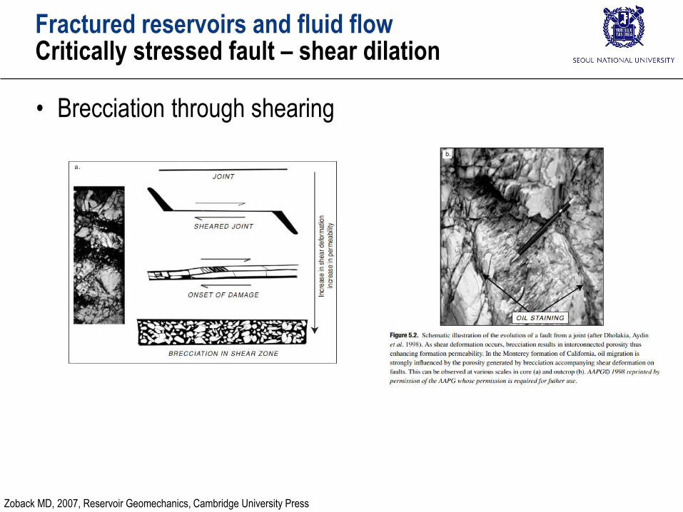
• Brecciation through shearing
Zoback MD, 2007, Reservoir Geomechanics, Cambridge University Press

• Direct shear test on 57 single fractures (Glamheden, 2007)
Fractured reservoirs and fluid flowCritically stressed fault – shear dilation and dilation angle
σn = 0.5 MPa
Ψmean = 14.6°
5 MPa
7.7°
20 MPa
3.2°
Glamheden R, Fredriksson A, Röshoff K, Karlsson J, Hakami H and Christiansson R (2007), Rock Mechanics Forsmark. Site descriptive modelling Forsmark stage 2.2. SKB.
- Shear dilation varies a lot at moderate normal stress (~ 20 MPa, ~ 500 m)
- At deep depth, dilation seems fairly small but it still enhance permeability a great deal
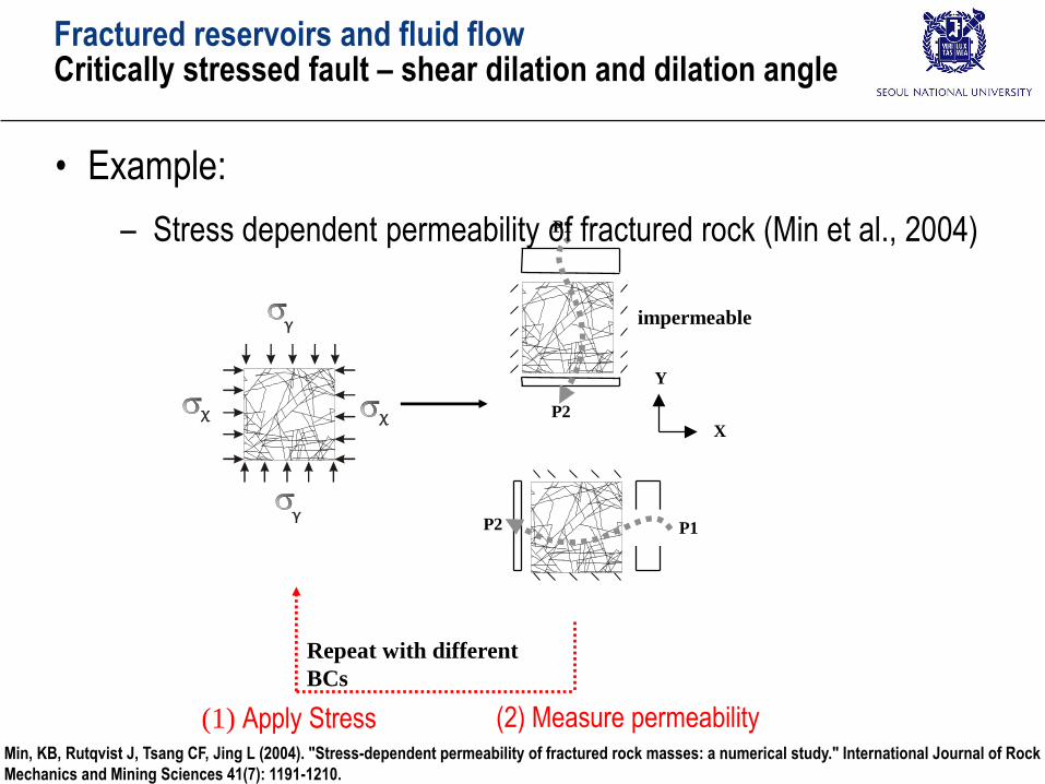
(1) Apply Stress (2) Measure permeability
X
Y
Y
X
P1
P2
P1P2
Y
X
impermeable
Repeat with different
BCs
Fractured reservoirs and fluid flowCritically stressed fault – shear dilation and dilation angle
• Example:
– Stress dependent permeability of fractured rock (Min et al., 2004)
Min, KB, Rutqvist J, Tsang CF, Jing L (2004). "Stress-dependent permeability of fractured rock masses: a numerical study." International Journal of Rock
Mechanics and Mining Sciences 41(7): 1191-1210.
Ratio of horizontal to vertical stress, k
Pe
rme
ab
ility
(m2)
0 1 2 3 4 510
-16
10-15
10-14
kx (MC model)
kx (elastic)
ky (MC model)
ky (elastic)
Contributionfrom dilation
Contributionfrom dilation
kx
kyDevelopment of
anisotropic permeability
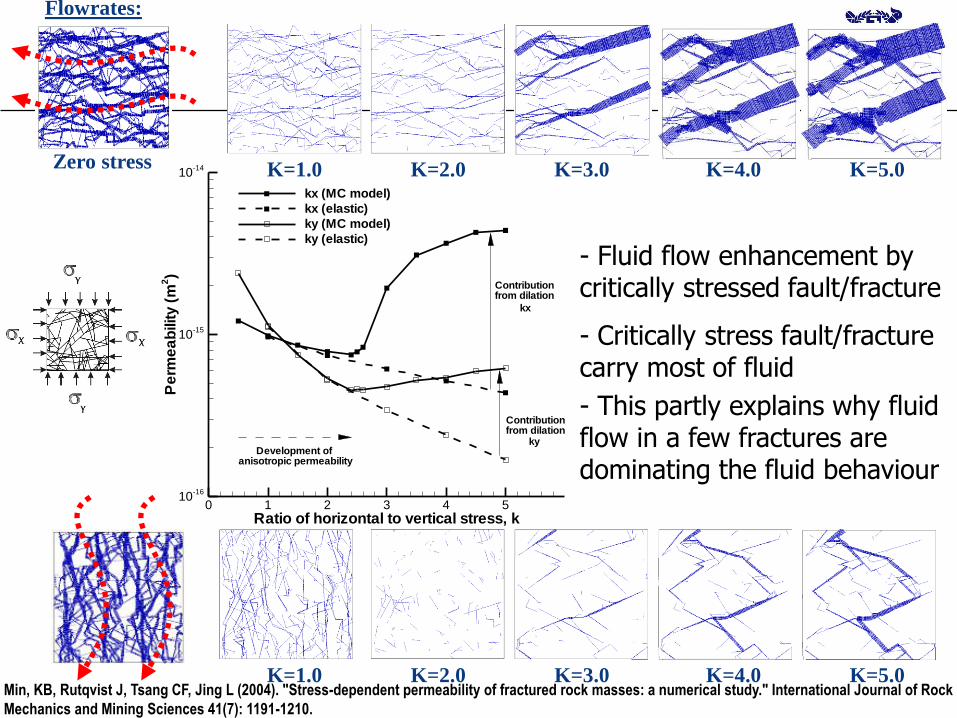
Zero stress
Flowrates:
K=1.0 K=2.0 K=3.0 K=4.0 K=5.0
K=1.0 K=2.0 K=3.0 K=4.0 K=5.0
- Fluid flow enhancement by critically stressed fault/fracture
- Critically stress fault/fracture carry most of fluid
- This partly explains why fluid flow in a few fractures are dominating the fluid behaviour
Min, KB, Rutqvist J, Tsang CF, Jing L (2004). "Stress-dependent permeability of fractured rock masses: a numerical study." International Journal of Rock
Mechanics and Mining Sciences 41(7): 1191-1210.

Fractured reservoirs and fluid flowCritically stressed fault – shear dilation and anisotropic fluid flow
• Shearing induce anisotropic flow in a fracture plane:
– Flow perpendicular to the shearing direction is much larger than that in parallel to the shearing
Koyama, T., et al. (2006). "Numerical simulation of shear-induced flow anisotropy and scale-dependent aperture and
transmissivity evolution of rock fracture replicas, IJRMMS;43(1): 89-106.
Rock fracture replica after shearing

Fractured reservoirs and fluid flowCalculation of normal and shear stress on a fault
• Calculation of normal and shear stress on the fault with given orientation
– Input: in situ stress, fault orientation, friction coefficient
– Normal (Sn) and shear (τ) stress acting on the plane
– Analysis: Coulomb failure analysis
τ = μ(Sn-Pp)
Fault orientation: = (n1, n2, n3)
unit normal vector

Fractured reservoirs and fluid flowCalculation of normal and shear stress on a fault
• Cauchy’s formula
– Input: stress tensor & unit normal vector of a plane (= fault)
– Output: Traction vector (stress vector) at the plane (= fault)
Fractured reservoirs and fluid flowCalculation of normal and shear stress on a fault
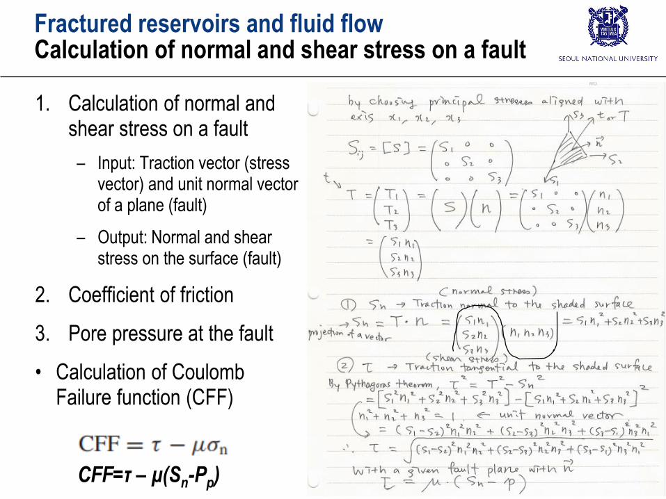
1. Calculation of normal and shear stress on a fault
– Input: Traction vector (stress vector) and unit normal vector of a plane (fault)
– Output: Normal and shear stress on the surface (fault)
2. Coefficient of friction
3. Pore pressure at the fault
• Calculation of Coulomb Failure function (CFF)
CFF=τ – μ(Sn-Pp)

Fractured reservoirs and fluid flowCritically stressed fault and conductive fault
• Examples
– Majorities of hydraulically conductive faults are critically stressed
Long Valley:
- Fractured metamorphic rock
- drilled ~ 2 km
- Investigation of the structure/caldera
- Strike-slip ~normal-slip stress regime
Cajon Pass
- Fractured Granite/granodiorate
- ~ 3.5 km
- ~ 4 km from the San Andreas fault
- Strike-slip ~ normal faulting
Nevada Test Site (Yucca Mountain project)
- Tuffaceous rock
- potential site for nuclear waste repository
- Hole was drilled >1.7 km
- Normal faulting
Hydraulically conductive Hydraulically non-conductive Orientation of wells that would intersect
the greatest number of critically stresses
faults
Zoback MD, 2007, Reservoir Geomechanics, Cambridge University Press

Fractured reservoirs and fluid flowCritically stressed fault and conductive fault
• Examples
– Majorities of hydraulically conductive faults are critically stressed
Cajon Pass (non-conductive)
Cajon Pass (conductive)
Nevada Test Site (non-conductive)
Nevada Test Site (conductive)
Long Valley (non-conductive)
Long Valley (conductive)
Zoback MD, 2007, Reservoir Geomechanics, Cambridge University Press

Fractured reservoirs and fluid flowCritically stressed fault and conductive fault
• Direction of fluid flow (permeability anisotropy)
Direction of the largest permeability
Direction of the 2nd largest permeability
Zoback MD, 2007, Reservoir Geomechanics, Cambridge University Press

Fractured reservoirs and fluid flowCritically stressed fault and conductive fault
• Relationship between critically stressed fault orientation and in situ stress
Normal
FaultingReverse
Faulting
CFF: Shear stress minus resistance.
(-) no slip, (+) slip
Pp/Sv: relative pore pressure required for shear slip
Critically stressed
Critically stressed
Zoback MD, 2007, Reservoir Geomechanics, Cambridge University Press
Fractured reservoirs and fluid flowCritically stressed fault and conductive fault
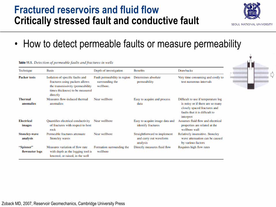
• How to detect permeable faults or measure permeability
Zoback MD, 2007, Reservoir Geomechanics, Cambridge University Press
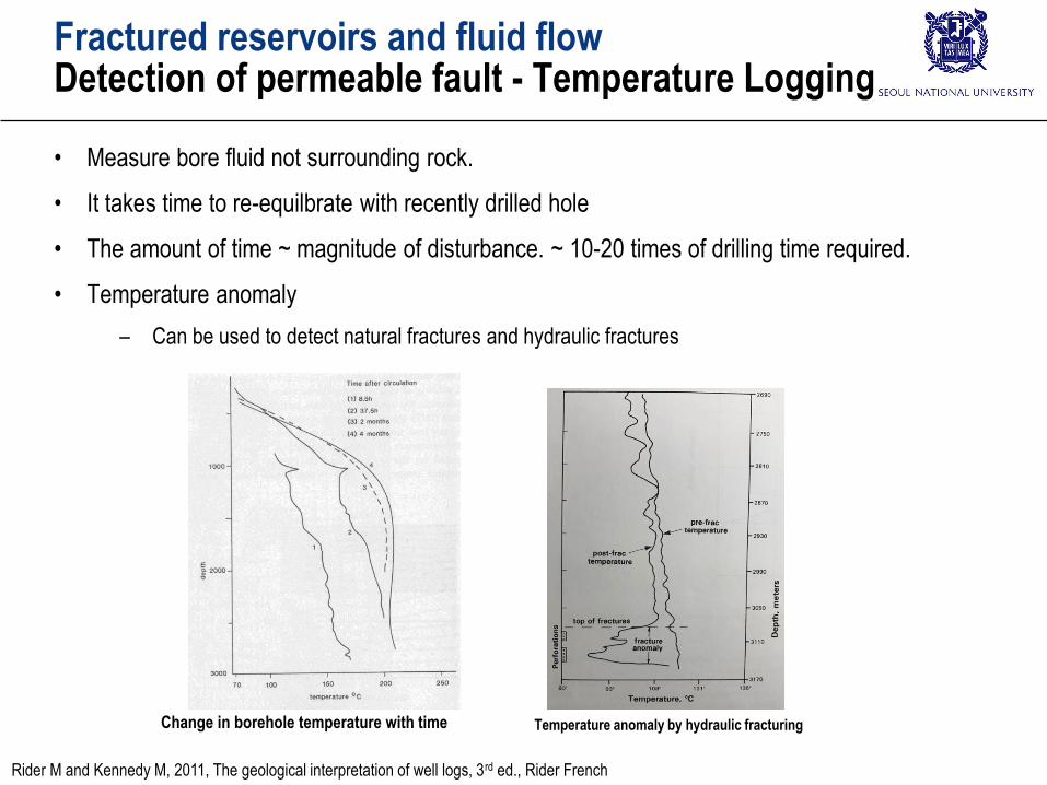
• Measure bore fluid not surrounding rock.
• It takes time to re-equilbrate with recently drilled hole
• The amount of time ~ magnitude of disturbance. ~ 10-20 times of drilling time required.
• Temperature anomaly
– Can be used to detect natural fractures and hydraulic fractures
Change in borehole temperature with time
Fractured reservoirs and fluid flowDetection of permeable fault - Temperature Logging
Temperature anomaly by hydraulic fracturing
Rider M and Kennedy M, 2011, The geological interpretation of well logs, 3rd ed., Rider French

Fractured reservoirs and fluid flowDetection of permeable fault - Spinner log
• Spinner
– An impeller used to measure fluid velocity
– Frequency proportional to the relative velocity between the tool and fluid
http://www.geothermal.uq.edu.au/06-October-2010
Spinner
0.8 m/s
1.2 m/s
Permeable zone
(fractures in fractured reservoir)
Rider M and Kennedy M, 2011, The geological interpretation of well logs, 3rd ed., Rider French

Critically stressed faultsCase Studies
• Example (Monterey formation, California)
– Under the same in situ stress condition, orientations of fractures are different and direction of major fluid flow varies
Critically stressed
Critically stressed fault:
Reverse faultCritically stressed fault:
Strike-slip
Critically stressed fault:
Strike-slip
Zoback MD, 2007, Reservoir Geomechanics, Cambridge University Press

Critically stressed faultsCase Studies
• Example (Monterey formation, California)
– Permeability may not increase even at critically stressed fault
Permeability
~100~1,000 md
Permeability ~0.1 md
Controlling factor of fault
permeability increase
- Degree of alteration and
cementation of brecciated
rock (fault sealing
- Diagenetic history
- Current effective normal
stress
- Precipitation in the fault
Diagenically immature shale
(속성이덜된셰일) slip may
not contribute to permeability
increase
Zoback MD, 2007, Reservoir Geomechanics, Cambridge University Press

Critically stressed faultsCase Studies
• Example: Sellafield project, UK
– Strike-slip faulting regime
– The orientation of permeable faults is exactly by hypothesis of ‘critically stress fault’.
All fractures
Fractures from
transmissive zone only
σHMax
σHMax
Zoback MD, 2007, Reservoir Geomechanics, Cambridge University Press

Critically stressed faultsCase Studies
• Example: Dixie Valley (Geothermal)
– Competition:
sealing due to precipitation in the fault Creation of permeability due to dilation and brecciation
competition
Zoback MD, 2007, Reservoir Geomechanics, Cambridge University Press
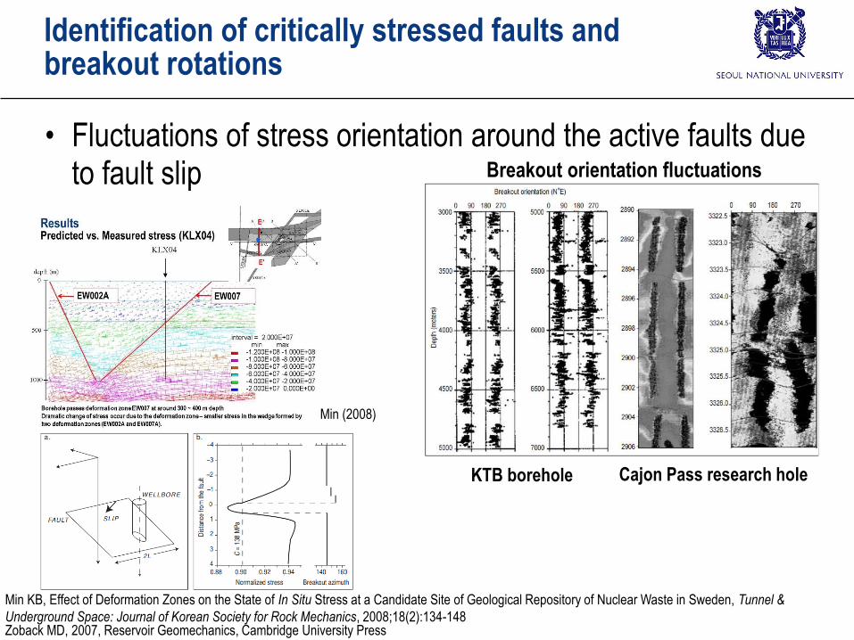
Identification of critically stressed faults and breakout rotations
• Fluctuations of stress orientation around the active faults due to fault slip
Min KB, Effect of Deformation Zones on the State of In Situ Stress at a Candidate Site of Geological Repository of Nuclear Waste in Sweden, Tunnel &
Underground Space: Journal of Korean Society for Rock Mechanics, 2008;18(2):134-148
Breakout orientation fluctuations
KTB borehole Cajon Pass research hole
Min (2008)
Zoback MD, 2007, Reservoir Geomechanics, Cambridge University Press

Intentionally induced microseismicity to enhance permeability
• Critically stressed fault can be used for hydraulic stimulation
• Example at Yufutsu gas field (Japan)
– Injection: 5,000m3 for 7 days
– Seismicity parallel to SHMAX
Zoback MD, 2007, Reservoir Geomechanics, Cambridge University Press

Fault seal/blown trap
• Critically stressed faults cut through reservoir
– Evidence of potentially large hydrocarbons in the past but not present today: blown trap problem
Zoback MD, 2007, Reservoir Geomechanics, Cambridge University Press
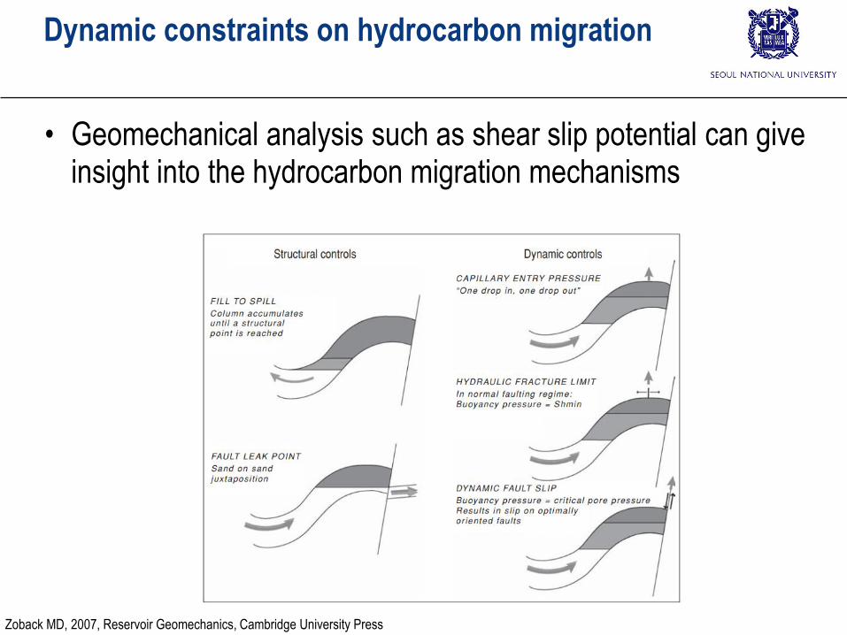
Dynamic constraints on hydrocarbon migration
• Geomechanical analysis such as shear slip potential can give insight into the hydrocarbon migration mechanisms
Zoback MD, 2007, Reservoir Geomechanics, Cambridge University Press