lecture-1 shear strength of soils
TRANSCRIPT

7/30/2019 Lecture-1 Shear Strength of Soils
http://slidepdf.com/reader/full/lecture-1-shear-strength-of-soils 1/97
CHAPTER ONE
Shear Strength of Soils
By Yada T.Nov/2012

7/30/2019 Lecture-1 Shear Strength of Soils
http://slidepdf.com/reader/full/lecture-1-shear-strength-of-soils 2/97
Introduction
In this chapter we will define, describe, anddetermine the shear strength of soils. When you
complete this chapter, you should be able to; Determine the shear strength of soils.
Understand the difference between drained and undrainedshear strength. Determine the type of shear test that best simulates field
conditions. Interpret laboratory and field test results to obtain shear
strength parameters.

7/30/2019 Lecture-1 Shear Strength of Soils
http://slidepdf.com/reader/full/lecture-1-shear-strength-of-soils 3/97
1.0 Introduction
The safety of any geotechnical structure is
dependent on the strength of the soil.
If the soil fails, a structure founded on it can collapse,
endangering lives and causing economic damages.
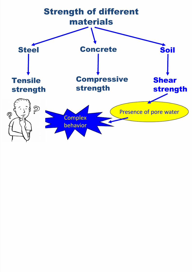
Soils fail either in tension or in shear.However, in the majority of soil mechanics problems
(such as bearing capacity, lateral pressure against
retaining walls, slope stability, etc.), only failure in
shear requires consideration.
7/30/2019 Lecture-1 Shear Strength of Soils
http://slidepdf.com/reader/full/lecture-1-shear-strength-of-soils 4/97
Strength of different
materials
Steel
Tensile
strength
Concrete
Compressive
strength
Soil
Shear
strength
Presence of pore waterComplex
behavior

7/30/2019 Lecture-1 Shear Strength of Soils
http://slidepdf.com/reader/full/lecture-1-shear-strength-of-soils 5/97
Cont.…
Expansive Soil

7/30/2019 Lecture-1 Shear Strength of Soils
http://slidepdf.com/reader/full/lecture-1-shear-strength-of-soils 6/97
Cont.…

7/30/2019 Lecture-1 Shear Strength of Soils
http://slidepdf.com/reader/full/lecture-1-shear-strength-of-soils 7/97
Cont…

7/30/2019 Lecture-1 Shear Strength of Soils
http://slidepdf.com/reader/full/lecture-1-shear-strength-of-soils 8/97
Typical "roller-
coaster" roadcaused by
expansive soils
Cracks in exterior walls, as aresult of upward soil
expansion

7/30/2019 Lecture-1 Shear Strength of Soils
http://slidepdf.com/reader/full/lecture-1-shear-strength-of-soils 9/97
Embankment
Strip footing
Shear failure of soils
Soils generally fail in shear
At failure, shear stress along the failure surface(mobilized shear resistance) reaches the shear strength.
Failure surface
Mobilized shear
resistance

7/30/2019 Lecture-1 Shear Strength of Soils
http://slidepdf.com/reader/full/lecture-1-shear-strength-of-soils 10/97
Retaining
wall
Shear failure of soils

7/30/2019 Lecture-1 Shear Strength of Soils
http://slidepdf.com/reader/full/lecture-1-shear-strength-of-soils 11/97
Retaining
wall
At failure, shear stress along the failure surface(mobilized shear resistance) reaches the shear strength.
Failure
surface
Mobilized shear
resistance
Shear failure of soils

7/30/2019 Lecture-1 Shear Strength of Soils
http://slidepdf.com/reader/full/lecture-1-shear-strength-of-soils 12/97
Shear failure mechanism
The soil grains slideover each other alongthe failure surface.
No crushing of individual grains.
failure surface

7/30/2019 Lecture-1 Shear Strength of Soils
http://slidepdf.com/reader/full/lecture-1-shear-strength-of-soils 13/97
Shear failure mechanism
At failure, shear stress along the failure surface ()reaches the shear strength (f ).

7/30/2019 Lecture-1 Shear Strength of Soils
http://slidepdf.com/reader/full/lecture-1-shear-strength-of-soils 14/97
Cont’d…
The shear strength of soils is, therefore, paramount
importance to geotechnical engineers.
The shear strength along any plane is mobilized by
cohesion and frictional resistance to sliding between
soil particles. The cohesion(c) and angle of friction (ϕ) of a soil are
collectively known as shear strength parameters.

7/30/2019 Lecture-1 Shear Strength of Soils
http://slidepdf.com/reader/full/lecture-1-shear-strength-of-soils 15/97
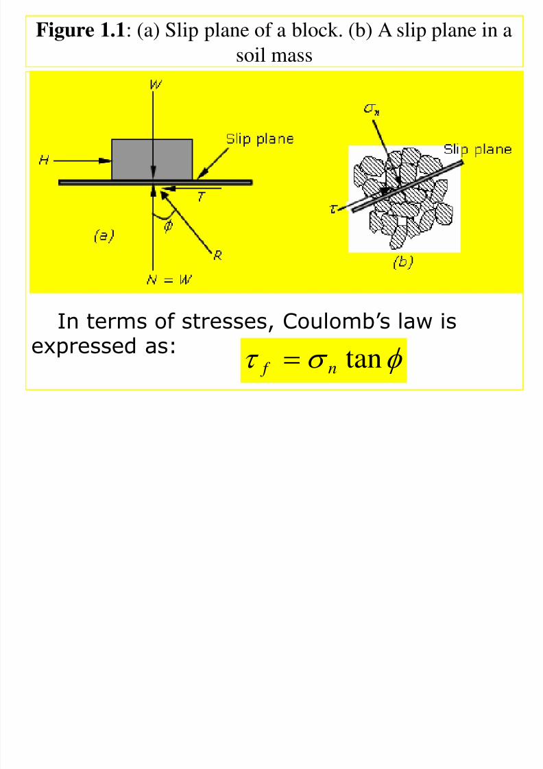
Coulomb’s Frictional Law
You may recall Coulomb’s frictional law from your
courses in statics and physics. If a block of weight (W)
is pushed horizontally on a plane (Fig. 1.1a), the
horizontal force ( H ) required to initiating movement
is:
Where:- µ=coefficient of static friction between the
block and the horizontal plane.
NB coefficient of static friction is independent of
the area of contact.
W H

7/30/2019 Lecture-1 Shear Strength of Soils
http://slidepdf.com/reader/full/lecture-1-shear-strength-of-soils 16/97
Cont’d…
• It is, however, strongly dependent on;
the nature of the surface in contact the type of material
the condition of the surface and so on.
The angle between the resultant force R and thenormal force N (Fig. 1.1) is called the friction angle
1
tan
7/30/2019 Lecture-1 Shear Strength of Soils
http://slidepdf.com/reader/full/lecture-1-shear-strength-of-soils 17/97
Figure 1.1: (a) Slip plane of a block. (b) A slip plane in a
soil mass
In terms of stresses, Coulomb’s law is
expressed as: tann f

7/30/2019 Lecture-1 Shear Strength of Soils
http://slidepdf.com/reader/full/lecture-1-shear-strength-of-soils 18/97
Cont’d…
Where:-
( = T/A) the shear stress when slip is initiated
( =N/A) the normal stress on the plane on which slip is
initiated
Coulomb’s law requires the existence or the
development of a critical sliding plane, also
called slip plane or failure plane. In the case of
the block the slip plane is at the interfacebetween the block and the horizontal plane.
f
n

7/30/2019 Lecture-1 Shear Strength of Soils
http://slidepdf.com/reader/full/lecture-1-shear-strength-of-soils 19/97
Mohr’s Circle for Stress
The stress states at a point within a soil mass can berepresented graphically by a very useful and widely
used devise known as Mohr’s circle for stress.
The stress state at a point is the set of stress vectors
corresponding to all planes passing through that point.
For simplicity, we will consider a two-dimensional
element with stresses as shown in Fig. 1.2a.
Let’s draw Mohr’s circle. First, we have to choose asign convention. In soil mechanics, compressive
stresses and clockwise shear are generally assumed to
be positive.

7/30/2019 Lecture-1 Shear Strength of Soils
http://slidepdf.com/reader/full/lecture-1-shear-strength-of-soils 20/97
Cont’d…
We will also assume that
x z
1 1

7/30/2019 Lecture-1 Shear Strength of Soils
http://slidepdf.com/reader/full/lecture-1-shear-strength-of-soils 21/97
Mohr’s Circle for Stress
The two coordinates of the circle are ( ) and
Recall from your strength of materials course that, for
equilibrium ..
Plot these two coordinates on a graph of shear stress(ordinate) and normal stress (abscissa) as shown by A
and B in Fig. above.
Draw a circle with AB as the diameter. The circle
crosses the normal stress axis at 1 and 3, where shear
stresses are equal to zero.
The stresses at these points are the major principal
stress, , and the minor principal stress, .
zx z ,
zx x ,
zx xz
11
1 3
zx ,

7/30/2019 Lecture-1 Shear Strength of Soils
http://slidepdf.com/reader/full/lecture-1-shear-strength-of-soils 22/97
Cont’d…
The principal stresses are related to the stresses
and by the following relations:
z x ,
z x ,
zx
2
2
1 22 zx
x z x z
2
2
322
zx x z x z
The angle between the major principal stressplane and the horizontal plane( ).

7/30/2019 Lecture-1 Shear Strength of Soils
http://slidepdf.com/reader/full/lecture-1-shear-strength-of-soils 23/97
Cont’d…
.
The stresses on a plane oriented at an angle
to the major principal stress plane are:
The maximum shear stress is at the top of the
circle with magnitude:
x
zx
1tan
2cos22
3131
2sin2
31

7/30/2019 Lecture-1 Shear Strength of Soils
http://slidepdf.com/reader/full/lecture-1-shear-strength-of-soils 24/97
Cont’d…
231
max

7/30/2019 Lecture-1 Shear Strength of Soils
http://slidepdf.com/reader/full/lecture-1-shear-strength-of-soils 25/97
Cont’d…

7/30/2019 Lecture-1 Shear Strength of Soils
http://slidepdf.com/reader/full/lecture-1-shear-strength-of-soils 26/97
Summary of today Session
Safety of geotechnical structures concerning bearing capacity,
slope stability, lateral earth pressure against retaining wall
problems are depend on shear strength of soils.
The cohesion(c) and angle of friction (ϕ) of a soil are known as
shear strength parameters.
Define cohesion and angle of friction of soil.
Derive major principal , minor principal stress and maximum
shear stress from Mohr's circle?
What is failure plane?
What is the fails happen in soil, concrete, and steel?
Search structure surround your environments failed
due to shear failure.Free charge
assignment
7/30/2019 Lecture-1 Shear Strength of Soils
http://slidepdf.com/reader/full/lecture-1-shear-strength-of-soils 27/97
.

7/30/2019 Lecture-1 Shear Strength of Soils
http://slidepdf.com/reader/full/lecture-1-shear-strength-of-soils 28/97
Next class:
Mohr-Coulomb Failure Criteria

7/30/2019 Lecture-1 Shear Strength of Soils
http://slidepdf.com/reader/full/lecture-1-shear-strength-of-soils 29/97
Mohr-Coulomb Failure Criteria
In 1900, Mohr presented a theory for rupture in
materials. According to this theory, failure along aplane in a material occurs by a critical combination of
normal and shear stresses, and not by normal or shear
stress alone.
The functional relation between normal and shear
stress on the failure plane can be given by
s=f( )
where:- S=shear stress at failure
= Normal stress on failure plane.

7/30/2019 Lecture-1 Shear Strength of Soils
http://slidepdf.com/reader/full/lecture-1-shear-strength-of-soils 30/97
Cont’d..
Coulomb (1776) suggested that the shear strength of a soil
along a failure plane could be described by:
Where:- c is cohesion and ϕ is the angle of friction of the soil.
This Equation is generally referred to as the Mohr –Coulomb
failure criteria.
tann f c

7/30/2019 Lecture-1 Shear Strength of Soils
http://slidepdf.com/reader/full/lecture-1-shear-strength-of-soils 31/97
Mohr-Coulomb Failure Criterion
(in terms of total stresses)
f is the maximum shear stress the soil can take without failure,
under normal stress of .
tan c f
c
CohesionFriction angle
f
7/30/2019 Lecture-1 Shear Strength of Soils
http://slidepdf.com/reader/full/lecture-1-shear-strength-of-soils 32/97
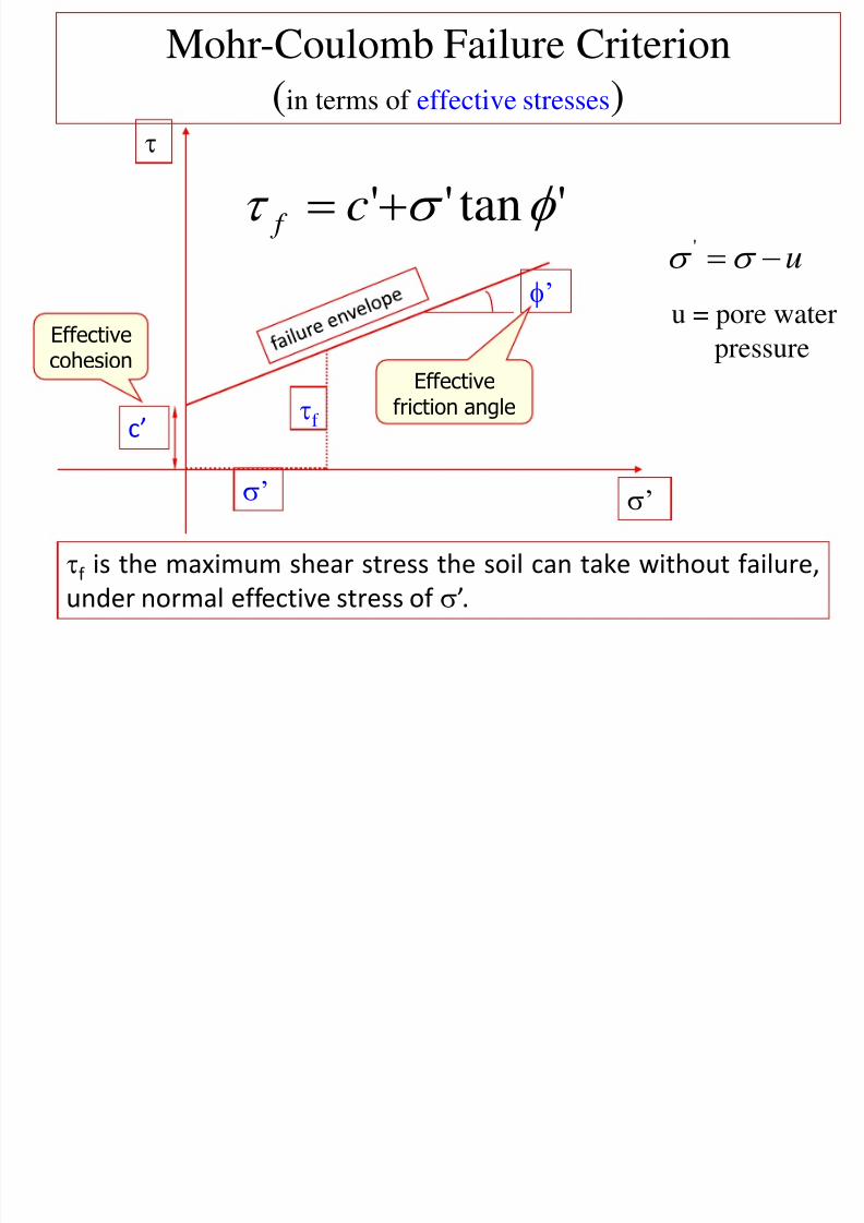
Mohr-Coulomb Failure Criterion
(in terms of effective stresses)
u '
f is the maximum shear stress the soil can take without failure,
under normal effective stress of ’.
’
'tan'' c f
c’
’ Effectivecohesion
Effectivefriction anglef
’
u = pore waterpressure

7/30/2019 Lecture-1 Shear Strength of Soils
http://slidepdf.com/reader/full/lecture-1-shear-strength-of-soils 33/97
Mohr-Coulomb Failure Criterion
'tan'' f f c
Shear strength consists of two components:
cohesive and frictional.
’f
f
’
'
c’ c’
’f tan ’ frictionalcomponent

7/30/2019 Lecture-1 Shear Strength of Soils
http://slidepdf.com/reader/full/lecture-1-shear-strength-of-soils 34/97
c and are measures of shear strength.
Higher the values, higher the shear strength.

7/30/2019 Lecture-1 Shear Strength of Soils
http://slidepdf.com/reader/full/lecture-1-shear-strength-of-soils 35/97
Soil elements at different locations
Failure surface
Mohr Circles & Failure Envelope
X X
X ~ failure
YY
Y ~ stable
’
'tan'' c f

7/30/2019 Lecture-1 Shear Strength of Soils
http://slidepdf.com/reader/full/lecture-1-shear-strength-of-soils 36/97
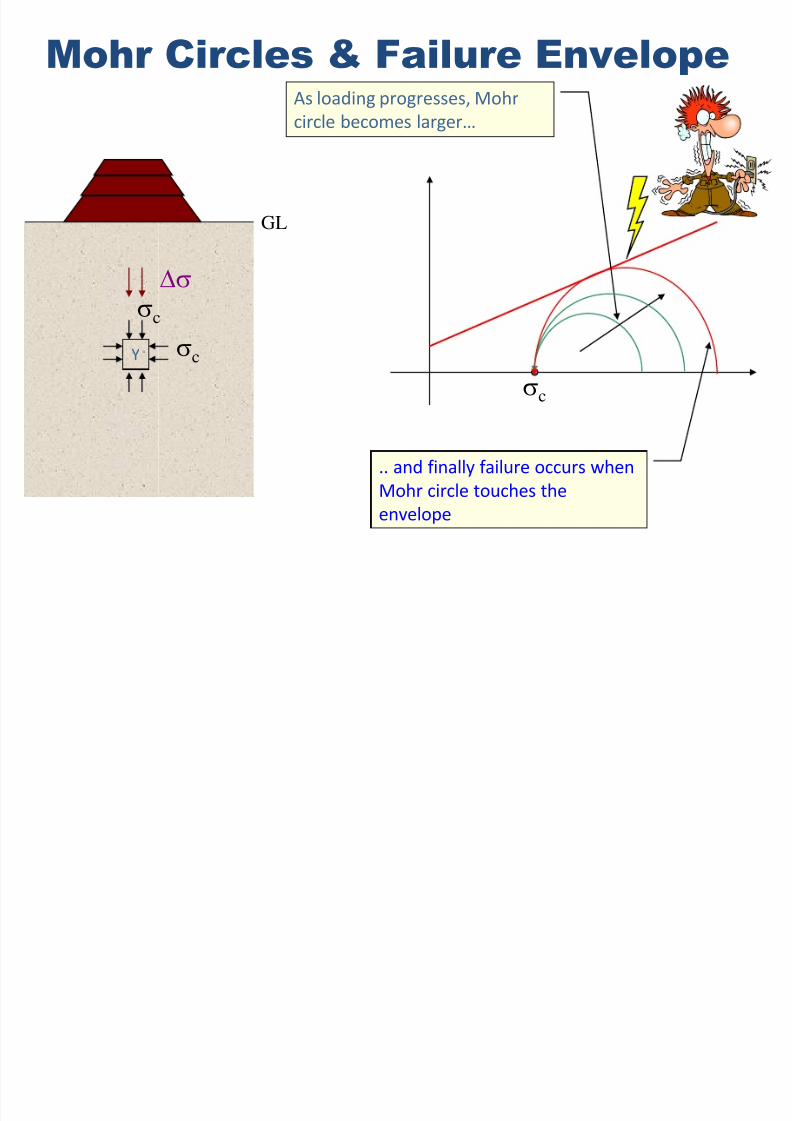
Mohr Circles & Failure Envelope
Y
c
c
c
Initially, Mohr circle is a point
c+
The soil element does not fail if
the Mohr circle is contained withinthe envelope
GL
7/30/2019 Lecture-1 Shear Strength of Soils
http://slidepdf.com/reader/full/lecture-1-shear-strength-of-soils 37/97
Mohr Circles & Failure Envelope
Y
c
c
c
GL
As loading progresses, Mohr
circle becomes larger…
.. and finally failure occurs when
Mohr circle touches the
envelope

7/30/2019 Lecture-1 Shear Strength of Soils
http://slidepdf.com/reader/full/lecture-1-shear-strength-of-soils 38/97
Mohr circles in terms of total & effective stresses
= X
v’
h’ X
u
u
+
v’ h’
effective stresses
uv h
X
v
h
total stresses
or ’
7/30/2019 Lecture-1 Shear Strength of Soils
http://slidepdf.com/reader/full/lecture-1-shear-strength-of-soils 39/97
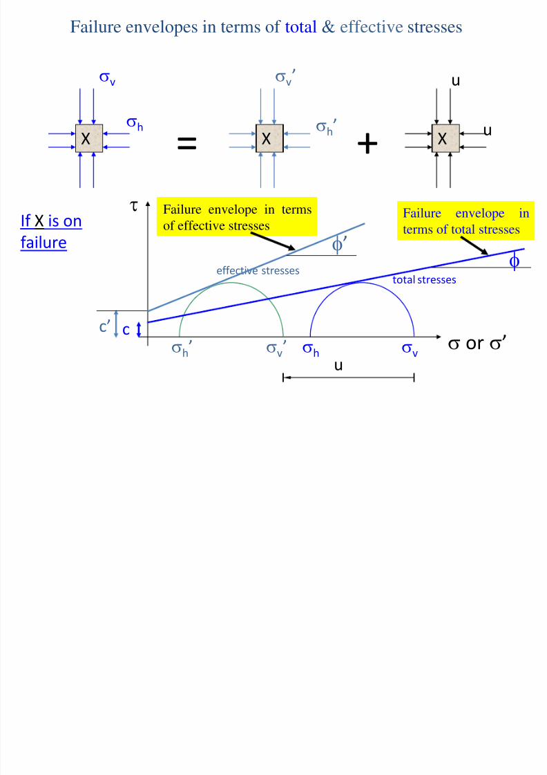
Failure envelopes in terms of total & effective stresses
= X
v’
h’ X
u
u
+
v’ h’
effective stresses
uv h
X
v
h
total stresses
or ’
If X is on
failure
c
Failure envelope in
terms of total stresses
’
c’
Failure envelope in terms
of effective stresses
Cont

7/30/2019 Lecture-1 Shear Strength of Soils
http://slidepdf.com/reader/full/lecture-1-shear-strength-of-soils 40/97
Cont.… • Mohr circle for effective and normal stresses
• Cohesion is the minimum shear strength at zero
normal stress, since tensile stress is ignored in the
soil or minimum.
'''
tan n f c
Cont

7/30/2019 Lecture-1 Shear Strength of Soils
http://slidepdf.com/reader/full/lecture-1-shear-strength-of-soils 41/97
Cont…
• From the above graph the equation becomes
• This equation can be written in terms of the
principal stresses
• Considering OB = c’ and OC = , we have
245
2
90 '0
'
''2
2''
sincos2
OC OBCF R zx x z
''
2'3
'1 sincos
2
OC OB
''3
'1
'''3
'1 sin)(cos2 c
2)( '3
'1
'
''
'
''3
'1'
'''
3'1
sin1
sin12
sin1
sin1
sin1
cos2
sin1
sin1
cc
Cont

7/30/2019 Lecture-1 Shear Strength of Soils
http://slidepdf.com/reader/full/lecture-1-shear-strength-of-soils 42/97
Cont…
or
or
'
''
'
''
1
'
3 sin1
sin1
2sin1
sin1
c
)2
45tan(2)2
45(tan'
''
2'3
'1
c
)245tan(2)245(tan
''
'2'
1
'
3
c
'
3'1
'
3
'
1'sin
'
'
'
1
'3
sin1
sin1
'
'
'
3
'1
sin1
sin1
)2
45(tan'
2
'
1
'3
)
245(tan
'2
'
3
'
1

7/30/2019 Lecture-1 Shear Strength of Soils
http://slidepdf.com/reader/full/lecture-1-shear-strength-of-soils 43/97
Drained and undrained Shear strength
Drained condition occurs when the excess pore water pressure
developed during loading of a soil dissipates, i.e.resulting in volume changes in the soil.
Loose sands, normally consolidated clays and lightly over
consolidated clays tend to compress or contract, whilst dense
sands and heavily over consolidated (OCR > 2) clays tend toexpand during drained condition.
Undrained condition occurs when the excess pore water
pressure cannot drain, at least quickly from the soil, i.e.
During undrained shearing, the volume of the soil remainsconstant. Consequently, the tendency towards volume change
induces a pressure in the pore water.
If the specimen tends to compress or contract during shear, then
the induced pore water pressure is positive.
0u
0u

7/30/2019 Lecture-1 Shear Strength of Soils
http://slidepdf.com/reader/full/lecture-1-shear-strength-of-soils 44/97
Cont’d..
Positive pore water pressures occur in loose sands, normally
consolidated clays and lightly over consolidated clays. If the specimen tends to expand and swell during shear, the
induced pore water pressure is negative. It wants to expand and
draw water into the pores, but it can not. Negative pore water
pressures occur in dense sands and heavily over consolidated(OCR > 2) clays.
The shear strength of a fine-grained soil under undrained
condition is called the undrained shear strength, Su. The
undrained shear strength Su is the radius of Mohr’s total stress
circle; that is
22
)()(
2
'
3
'
1
'
3
'
131
uuS u

7/30/2019 Lecture-1 Shear Strength of Soils
http://slidepdf.com/reader/full/lecture-1-shear-strength-of-soils 45/97
1, A sample of clay has a cohesive strength of 80kN/m2,and
an angle of shearing resistance of 100.calculate the
shearing strength of clay at a normal stress of 100kN/m2
Solution - 1
Given c = 80kN/m
= 100 and
= 100kN/m2
The shearing strength is
tan
c20
/ 63.9710tan10080 mkN

7/30/2019 Lecture-1 Shear Strength of Soils
http://slidepdf.com/reader/full/lecture-1-shear-strength-of-soils 46/97
• A cube sample of soil 100 mm×100 mm is subjected to
the forces shown in Fig. below. Determine
(a) The principal stress 1 & 3.
(b) The maximum shear stress, and
(c) The stresses on a plane oriented at Ѳ=300 clockwise
to the major principal stress plane.
SOLUTION 2

7/30/2019 Lecture-1 Shear Strength of Soils
http://slidepdf.com/reader/full/lecture-1-shear-strength-of-soils 47/97
SOLUTION -2
• Thus
• The principal stresses are:
• Max shear stress
500
1.0*1.0
5
A
F z z
3001.0*1.0
3
A
F x x
100
1.0*1.0
1
A
T xz
1001.0*1.0
1
A
T zx
kpa42.541)100(2
300500
2
300500 2
2
1
kpa58.258)100(2
300500
2
300500 2
2
3
42.1412
58.25842.541
2
31max
SOLUTION 2

7/30/2019 Lecture-1 Shear Strength of Soils
http://slidepdf.com/reader/full/lecture-1-shear-strength-of-soils 48/97
SOLUTION - 2
The stress on a plane(Ѳ=300 cw = 150 ccw) is given by:-
The angle between major principal plane and horizontal
plane :-
01
1
15.22]
30042.541
100[tan][tan
x
zx
kpa71.470150*2cos2
58.25842.541
2
58.25842.541
2cos22
3131
KPa47.122150*2sin2
58.25842.5412sin
2
31
D t i ti f h t th t f

7/30/2019 Lecture-1 Shear Strength of Soils
http://slidepdf.com/reader/full/lecture-1-shear-strength-of-soils 49/97
Determination of shear strength parameters of
soils (c, or c’, ’)
Laboratory tests on specimens
taken from representative
undisturbed samples
Field tests
Most common laboratory tests
to determine the shear strength
parameters are,
1.Direct shear test2.Triaxial shear test
3. unconfined compression test
1.Vane shear test
2. Cone penetration test
3.Standard penetration test
4. Pocket penetrometer
5. Fall cone6. Pressuremeter

7/30/2019 Lecture-1 Shear Strength of Soils
http://slidepdf.com/reader/full/lecture-1-shear-strength-of-soils 50/97
Preconsolidation Stress or past maximum effective stress, is themaximum vertical effective stress that a soil was subjected to in
the past σ’zc.
• Normally Consolidated Soil is one that has never experienced
vertical effective stresses greater than its current verticaleffective stress (σ’zc = σ’zo ).
• Over consolidated Soil is one that has experienced vertical
effective stresses greater than its current vertical effective stress
(σ’zo<σ’zc ).• Over consolidation ratio, OCR , is the ratio by which the current
vertical effective stress in the soil was exceeded in the past
(OCR = σ’zc / σ’zo ).
Remember those key terms
L b t t t

7/30/2019 Lecture-1 Shear Strength of Soils
http://slidepdf.com/reader/full/lecture-1-shear-strength-of-soils 51/97
Laboratory tests
Field conditions
z
vc
vc
hchc
Before construction
A representative
soil samplez
vc +
hchc
After and during
construction
vc +
Laboratory tests
vc +

7/30/2019 Lecture-1 Shear Strength of Soils
http://slidepdf.com/reader/full/lecture-1-shear-strength-of-soils 52/97
Laboratory tests
Simulating field conditions in
the laboratory
Step 1Set the specimen in
the apparatus and
apply the initial
stress condition
vc
vc
hchc
Representative soilsample taken
from the site
0
00
0
Step 2
Apply the
corresponding field
stress conditions
hchc
vc +
vc
vc
1 Di h
7/30/2019 Lecture-1 Shear Strength of Soils
http://slidepdf.com/reader/full/lecture-1-shear-strength-of-soils 53/97
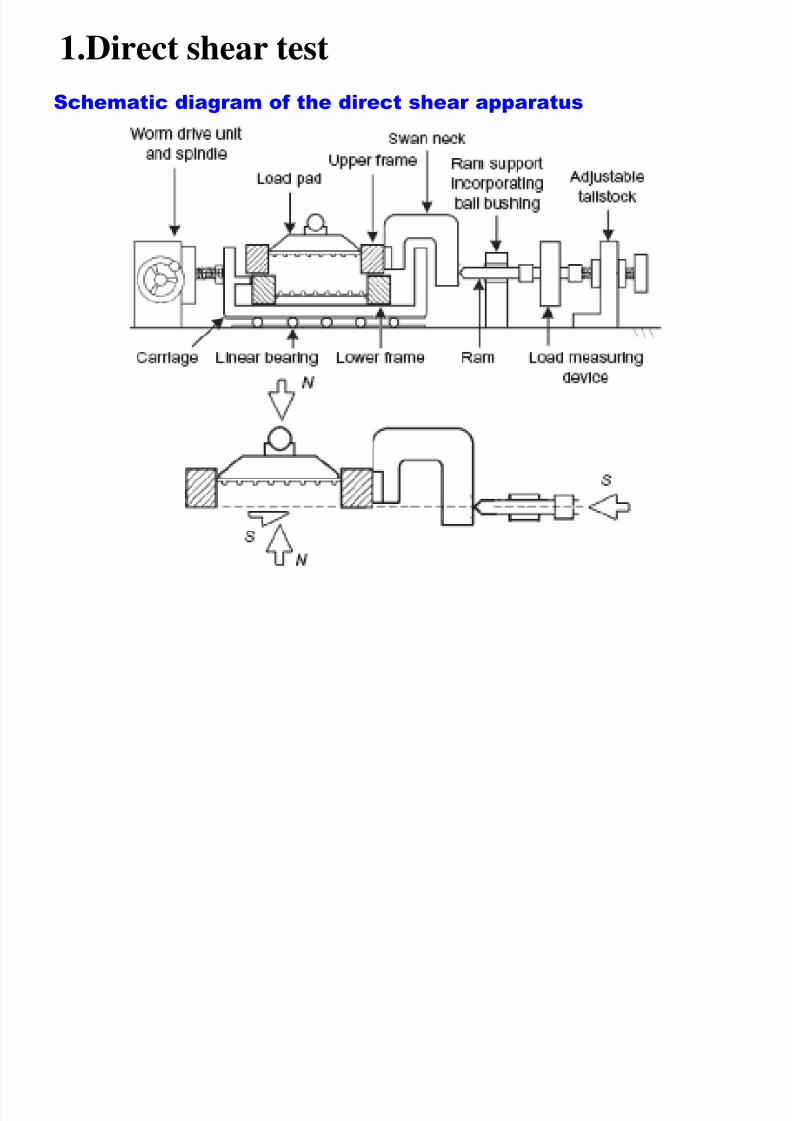
1.Direct shear test
Schematic diagram of the direct shear apparatus
Direct shear test

7/30/2019 Lecture-1 Shear Strength of Soils
http://slidepdf.com/reader/full/lecture-1-shear-strength-of-soils 54/97
Direct shear test
Preparation of a sand specimen
Components of the shear box Preparation of a sand specimen
Porous
plates
Direct shear test is most suitable for consolidated drained tests
specially on granular soils (e.g.: sand) or stiff clays
Di t h t t

7/30/2019 Lecture-1 Shear Strength of Soils
http://slidepdf.com/reader/full/lecture-1-shear-strength-of-soils 55/97
Direct shear test
Leveling the top surface of
specimen
Preparation of a sand specimen
Specimen preparation
completed
Pressure plate
Direct shear test

7/30/2019 Lecture-1 Shear Strength of Soils
http://slidepdf.com/reader/full/lecture-1-shear-strength-of-soils 56/97
Direct shear test
Test procedure
Porous
plates
Pressure plate
Steel ball
Step 1: Apply a vertical load to the specimen and wait for consolidation
P
Proving ring to
measure shear
force
S
Direct shear test

7/30/2019 Lecture-1 Shear Strength of Soils
http://slidepdf.com/reader/full/lecture-1-shear-strength-of-soils 57/97
Direct shear test
Step 2: Lower box is subjected to a horizontal displacement at a constant rate
Step 1: Apply a vertical load to the specimen and wait for consolidation
PTest procedure
Pressure plate
Steel ball
Proving ring to
measure shear
force
S
Porous
plates
Interface tests on direct shear apparatus

7/30/2019 Lecture-1 Shear Strength of Soils
http://slidepdf.com/reader/full/lecture-1-shear-strength-of-soils 58/97
Interface tests on direct shear apparatus
In many foundation design problems and retaining wall problems, it is required
to determine the angle of internal friction between soil and the structural
material (concrete, steel or wood)
tan' a f cWhere,
ca = adhesion,
= angle of internal friction
Foundation material
Soil
P
S
Foundation material
Soil
P
S
Th di h b i l l li bl h
7/30/2019 Lecture-1 Shear Strength of Soils
http://slidepdf.com/reader/full/lecture-1-shear-strength-of-soils 59/97
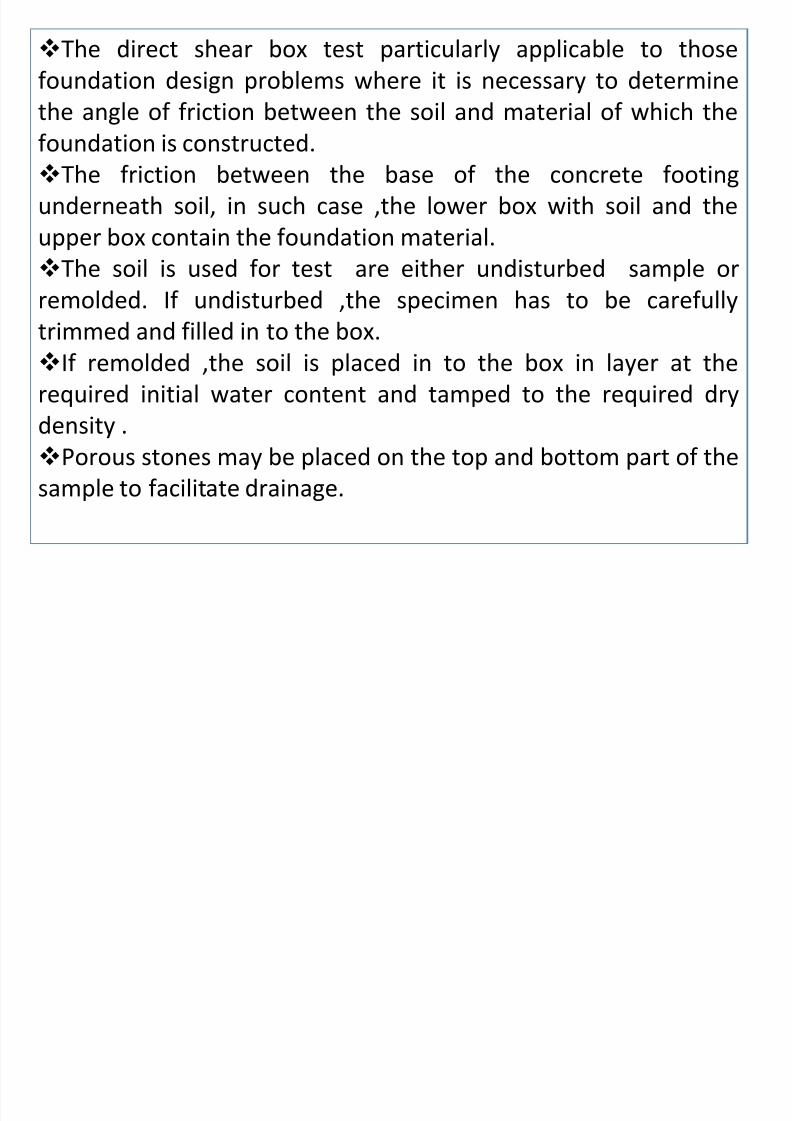
The direct shear box test particularly applicable to those
foundation design problems where it is necessary to determine
the angle of friction between the soil and material of which the
foundation is constructed.The friction between the base of the concrete footing
underneath soil, in such case ,the lower box with soil and the
upper box contain the foundation material.
The soil is used for test are either undisturbed sample or
remolded. If undisturbed ,the specimen has to be carefully
trimmed and filled in to the box.
If remolded ,the soil is placed in to the box in layer at the
required initial water content and tamped to the required dry
density .Porous stones may be placed on the top and bottom part of the
sample to facilitate drainage.
Direct shear test

7/30/2019 Lecture-1 Shear Strength of Soils
http://slidepdf.com/reader/full/lecture-1-shear-strength-of-soils 60/97
Direct shear test
Shear box
Loading frame toapply vertical load
Dial gauge to
measure vertical
displacement
Dial gauge to measurehorizontal displacement
Proving ring to
measure shear
force
Observation/ analysis test results

7/30/2019 Lecture-1 Shear Strength of Soils
http://slidepdf.com/reader/full/lecture-1-shear-strength-of-soils 61/97
Observation/ analysis test results
1. For each specimen plot the shear stress Vs shear
displacement (horizontal displacement).
Plot the graph of shear strength Vs normal stress for the threespecimens and calculate the shear strength parameters for the
soil.
Type of Test : Direct shear test. Deter. of moisture content
Calibration factor = __ Moisture Content (%) =___
Normal Load Applied = 1,2,3 kg *9.81m/s²
Horizontal Dial Gauge Constant: 20 Division
Calibration factor=0.001mm/Division
Due to normal load_________ Normal stress_________Kpa
ARBA MINCH UNIVERSITY
CIVIL ENGINEERING DEPARTMENT

7/30/2019 Lecture-1 Shear Strength of Soils
http://slidepdf.com/reader/full/lecture-1-shear-strength-of-soils 62/97
GEOTECHNICAL ENGINEERING LABORATORY
Direct Shear Test
Project:
LOCATION:
Sample No. TP 2 Sample Depth, m: 2.20Thickness of sample: 25 mm Ring Calib. Factor: 0.70 N/div Wet unit weight, kN/M3: 18.56
Length of sample : 60 mm Rate of strain : 0.1 mm/min Dry Unit Weight, kN/M3: 14.62
Width of sample: 60 mm Moisture content, % 27.0 Sample Condition: Disturbed
Applied Vertical Stress 100 kPa Applied Vertical Stress 200 kPa Applied Vertical Stress 300 kPa
Horizontal
Displacement [mm]
Corrected
Area[mm2]
Proving
Ring Reading
Shear load[N]
Shear
Stress[kPa]
Proving
Ring Reading
Shear load[N]
Shear
Stress[kPa]
Proving
Ring Reading
Shear load[N]
Shear
Stress[kPa]
0.0 3600 0.00 0.00 0.00 0.00 0.00 0.00 0.00 0.00 0.00
0.5 3570 50.00 35.00 9.80 90.00 63.00 17.65 110.00 77.00 21.57
1.0 3540 75.00 52.50 14.83 110.00 77.00 21.75 130.00 91.00 25.71
1.5 3510 105.00 73.50 20.94 140.00 98.00 27.92 170.00 119.00 33.90
2.0 3480 140.00 98.00 28.16 170.00 119.00 34.20 195.00 136.50 39.222.5 3450 175.00 122.50 35.51 200.00 140.00 40.58 230.00 161.00 46.67
3.0 3420 190.00 133.00 38.89 230.00 161.00 47.08 258.00 180.60 52.81
3.5 3390 210.00 147.00 43.36 260.00 182.00 53.69 300.00 210.00 61.95
4.0 3360 240.00 168.00 50.00 290.00 203.00 60.42 340.00 238.00 70.83
5.0 2880 - - - - - - 610.00 427.00 148.26
Max. shear stress,kPa 50.00 Max. shear stress,kPa 60.42 Max. shear stress,kPa 148.26

7/30/2019 Lecture-1 Shear Strength of Soils
http://slidepdf.com/reader/full/lecture-1-shear-strength-of-soils 63/97
Analysis of test results
sampletheof sectioncrossof Area(P)forceNormal stressNormal
sampletheof sectioncrossof Area
(S)surfaceslidingat thedevelopedresistanceShearstressShear
Note: Cross-sectional area of the sample changes with the horizontal
displacement
Shear load = Proving ring reading x Ring Calibration Factor
Corrected Cross-sectional =Ao[1+[ΔL⁄3]]
Direct shear tests on sands

7/30/2019 Lecture-1 Shear Strength of Soils
http://slidepdf.com/reader/full/lecture-1-shear-strength-of-soils 64/97
f1
Normal stress = 1
How to determine strength parameters c and
S h e a r s t r e s s ,
Shear displacement
f2
Normal stress = 2
f3
Normal stress = 3
S h e a r s t r e s s a t f a
i l u r e , f
Normal stress,
Mohr – Coulomb failure envelope
Direct shear tests on sands

7/30/2019 Lecture-1 Shear Strength of Soils
http://slidepdf.com/reader/full/lecture-1-shear-strength-of-soils 65/97
Some important facts on strength parameters c and of sand
Sand is cohesionless hence
c = 0
Direct shear tests are drainedand pore water pressures are
dissipated, hence u = 0
Therefore,
’ = and c’ = c = 0
Direct shear tests on clays

7/30/2019 Lecture-1 Shear Strength of Soils
http://slidepdf.com/reader/full/lecture-1-shear-strength-of-soils 66/97
Direct shear tests on clays
Failure envelopes for clay from drained direct shear tests
S h e a r s t r e
s s a t f a i l u r e , f
Normal force,
’
Normally consolidated clay (c’ = 0)
In case of clay, horizontal displacement should be applied at a very
slow rate to allow dissipation of pore water pressure (therefore, one
test would take several days to finish)
Overconsolidated clay (c’ ≠ 0)
Advantages of direct shear apparatus

7/30/2019 Lecture-1 Shear Strength of Soils
http://slidepdf.com/reader/full/lecture-1-shear-strength-of-soils 67/97
Advantages of direct shear apparatus
Due to the smaller thickness of the sample, rapid drainage can
be achieved
Can be used to determine strength parameters c and
Clay samples can be oriented along the plane of weakness or
an identified failure plane
Disadvantages of direct shear apparatus
Failure occurs along a predetermined failure plane
Area of the sliding surface changes as the test progresses
Non-uniform distribution of shear stress along the failure surface
2.Triaxial Shear Test
7/30/2019 Lecture-1 Shear Strength of Soils
http://slidepdf.com/reader/full/lecture-1-shear-strength-of-soils 68/97
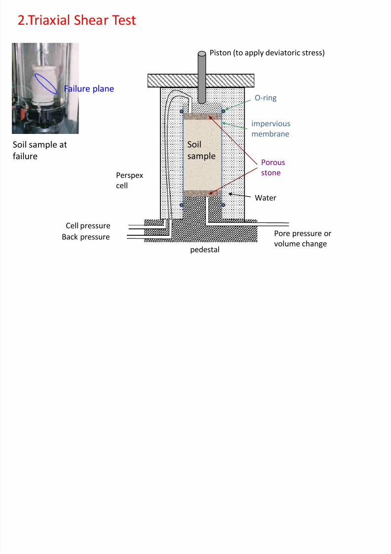
2.Triaxial Shear Test
Soil sample atfailure
Failure plane
Porous
stone
impervious
membrane
Piston (to apply deviatoric stress)
O-ring
pedestal
Perspex
cell
Cell pressure
Back pressure Pore pressure or
volume change
Water
Soilsample
Triaxial Shear Test
7/30/2019 Lecture-1 Shear Strength of Soils
http://slidepdf.com/reader/full/lecture-1-shear-strength-of-soils 69/97
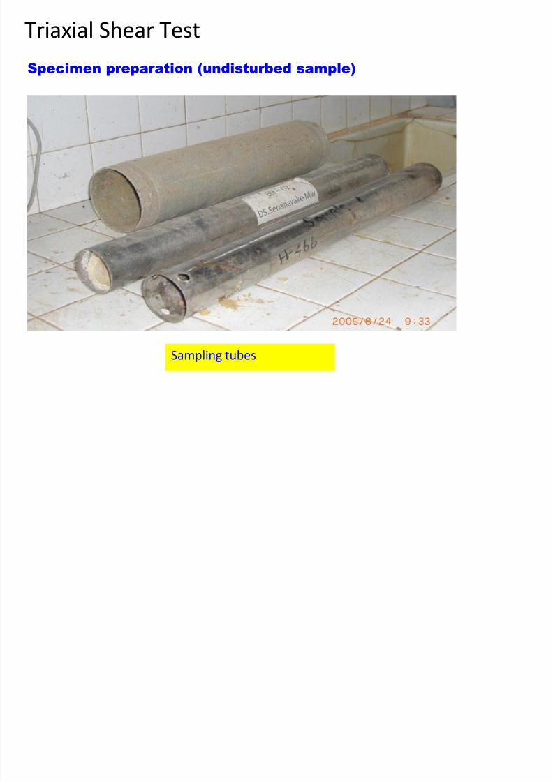
Triaxial Shear Test
Specimen preparation (undisturbed sample)
Sampling tubes
Triaxial Shear Test

7/30/2019 Lecture-1 Shear Strength of Soils
http://slidepdf.com/reader/full/lecture-1-shear-strength-of-soils 70/97
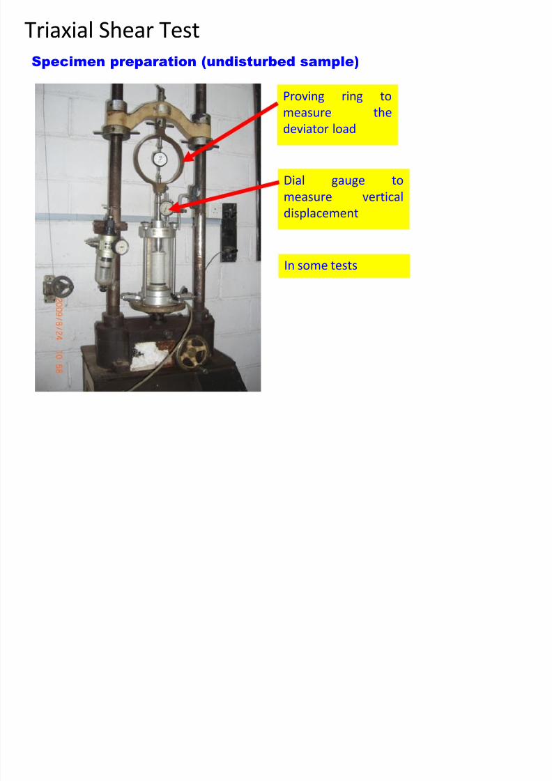
Triaxial Shear Test
Specimen preparation (undisturbed sample)
Edges of the sample are
carefully trimmed
Setting up the sample in the
triaxial cell
Triaxial Shear Test

7/30/2019 Lecture-1 Shear Strength of Soils
http://slidepdf.com/reader/full/lecture-1-shear-strength-of-soils 71/97
Triaxial Shear Test
Sample is covered with a
rubber membrane and sealed Cell is completely filled
with water
Specimen preparation (undisturbed sample)
Triaxial Shear Test
7/30/2019 Lecture-1 Shear Strength of Soils
http://slidepdf.com/reader/full/lecture-1-shear-strength-of-soils 72/97
Triaxial Shear Test
Specimen preparation (undisturbed sample)
Proving ring to
measure the
deviator load
Dial gauge to
measure verticaldisplacement
In some tests
Types of Triaxial Tests deviatoric stress

7/30/2019 Lecture-1 Shear Strength of Soils
http://slidepdf.com/reader/full/lecture-1-shear-strength-of-soils 73/97
Is the drainage valve open?
yes no
Consolidated
sampleUnconsolidated
sample
Is the drainage valve open?
yes no
Drained
loading
Undrained
loading
Under all-around cell pressure c
cc
c
cStep 1
( = q)
Shearing (loading)
Step 2
c c
c+ q
Consolidated- drained test (CD Test)

7/30/2019 Lecture-1 Shear Strength of Soils
http://slidepdf.com/reader/full/lecture-1-shear-strength-of-soils 74/97
Deviator stress (q or d) = 1 – 3
( )
1 = VC +
3 = hC
CD tests How to determine strength parameters c and

7/30/2019 Lecture-1 Shear Strength of Soils
http://slidepdf.com/reader/full/lecture-1-shear-strength-of-soils 75/97
D e v i a t o r s t r e s s ,
d
Axial strain
S h e a r
s t r e s s ,
or ’
Mohr – Coulomb
failure envelope
(d)fa
Confining stress = 3a(d)fb
Confining stress = 3b
(d)fc
Confining stress = 3c
3c 1c3a 1a
(d
)fa
3b 1b
(d)fb
1 = 3 + (d)f
3
CD tests

7/30/2019 Lecture-1 Shear Strength of Soils
http://slidepdf.com/reader/full/lecture-1-shear-strength-of-soils 76/97
Strength parameters c and obtained from CD tests
Since u = 0 in CD
tests, = ’
Therefore, c = c’
and = ’
cd and d are used todenote them
CD tests Failure envelopes

7/30/2019 Lecture-1 Shear Strength of Soils
http://slidepdf.com/reader/full/lecture-1-shear-strength-of-soils 77/97
S h e a r s t r
e s s ,
or ’
d
Mohr – Coulomb
failure envelope
3a 1a
(d)fa
For sand and NC Clay, cd = 0
Therefore, one CD test would be sufficient to determine d of sand
or NC clay
CD tests Failure envelopes

7/30/2019 Lecture-1 Shear Strength of Soils
http://slidepdf.com/reader/full/lecture-1-shear-strength-of-soils 78/97
For OC Clay, cd ≠ 0
NC clay, cd =0
or ’
3 1
(d)f
c
c
OC NC
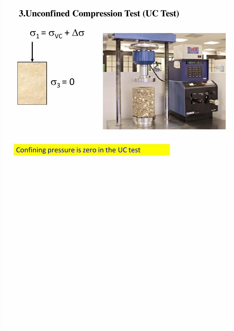
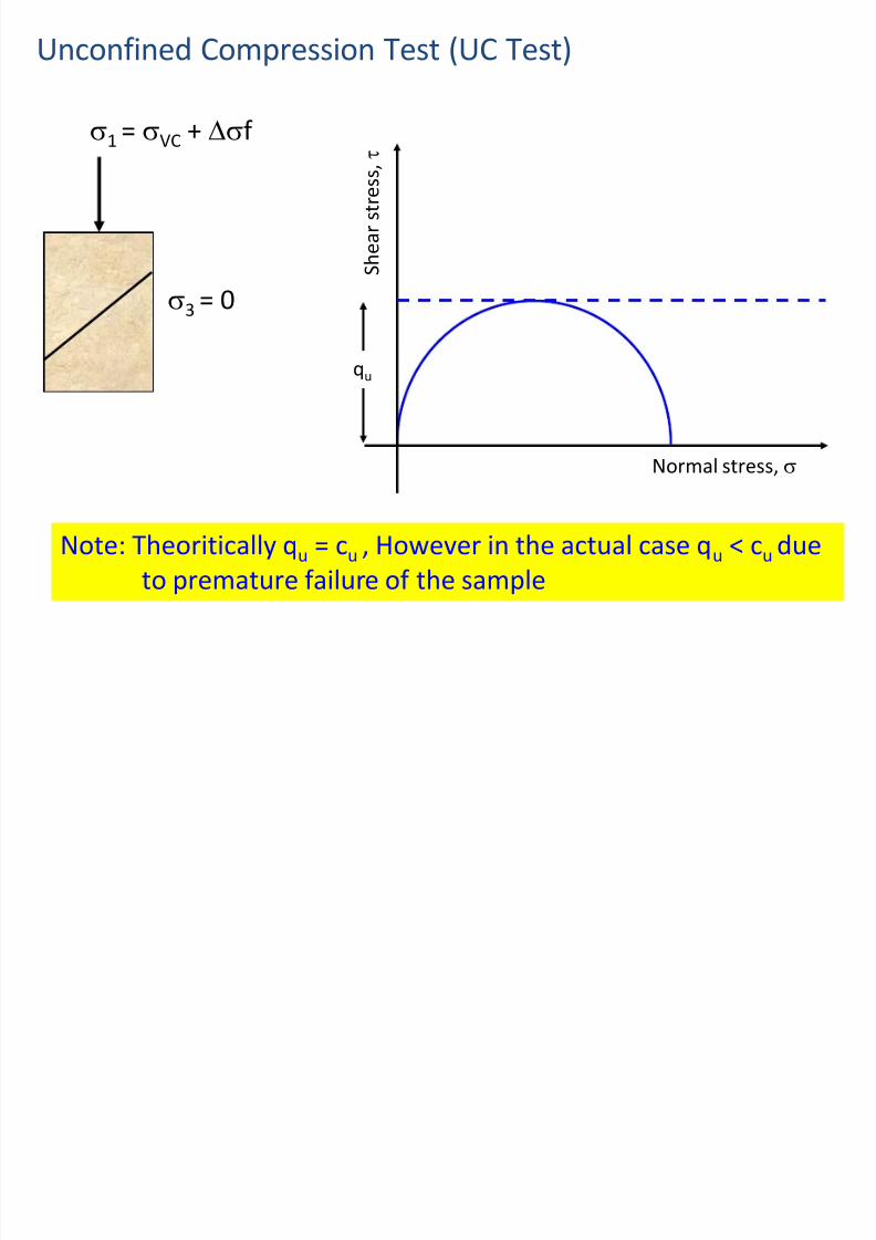
3.Unconfined Compression Test (UC Test)
7/30/2019 Lecture-1 Shear Strength of Soils
http://slidepdf.com/reader/full/lecture-1-shear-strength-of-soils 79/97
p ( )
1 = VC +
3 = 0
Confining pressure is zero in the UC test
Unconfined Compression Test (UC Test)
7/30/2019 Lecture-1 Shear Strength of Soils
http://slidepdf.com/reader/full/lecture-1-shear-strength-of-soils 80/97
p ( )
1 = VC + f
3
= 0
S h e a r s t r e s s ,
Normal stress,
qu
Note: Theoritically qu = cu , However in the actual case qu < cu due
to premature failure of the sample
A i t #1

7/30/2019 Lecture-1 Shear Strength of Soils
http://slidepdf.com/reader/full/lecture-1-shear-strength-of-soils 81/97
Assignment #1
Due date:- @ Next Class

7/30/2019 Lecture-1 Shear Strength of Soils
http://slidepdf.com/reader/full/lecture-1-shear-strength-of-soils 82/97
In-situ/ Field Tests/ shear tests
Vane shear test Cone penetration test
Standard penetration test
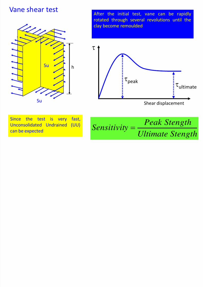
1. Vane shear test
In soft and saturated clays, where undisturbedspecimen is difficult to obtain, the undrained shearstrength is measured using a shear vane test.
A diagrammatic view of the shear vane apparatus is
shown in Fig. below. It consists of four thin metal blades welded
orthogonally (900) to a rod where the height H is twicethe diameter D. Commonly used diameters are 38, 50and 75 mm.
1.Vane shear test

7/30/2019 Lecture-1 Shear Strength of Soils
http://slidepdf.com/reader/full/lecture-1-shear-strength-of-soils 83/97
PLAN VIEW
This is one of the most versatile and widely used devices used for investigating
undrained shear strength (Su) and sensitivity of soft clays
Bore hole (diameter
= DB)
h > 3DB)
Vane
D
H
AppliedTorque, T
Vane T
Rupture
surfaceDisturbed
soil
Rate of rotation : 60 – 120 per minute
Test can be conducted at 0.5 m vertical
intervals

7/30/2019 Lecture-1 Shear Strength of Soils
http://slidepdf.com/reader/full/lecture-1-shear-strength-of-soils 84/97
Vane shear testAfter the initial test, vane can be rapidly
7/30/2019 Lecture-1 Shear Strength of Soils
http://slidepdf.com/reader/full/lecture-1-shear-strength-of-soils 85/97
Since the test is very fast,
Unconsolidated Undrained (UU)
can be expected
Su
Su
h
, p y
rotated through several revolutions until the
clay become remoulded
peakultimate
Shear displacement
StengthUltimate
StengthPeak ySensitivit
Some important facts on vane shear test

7/30/2019 Lecture-1 Shear Strength of Soils
http://slidepdf.com/reader/full/lecture-1-shear-strength-of-soils 86/97
Insertion of vane into soft clays
and silts disrupts the natural soilstructure around the vane causing
reduction of shear strength
The above reduction is
partially regained aftersome time
Cu as determined by vane
shear test may be a
function of the rate of
angular rotation of the
vane
Correction for the strength parameters obtained from

7/30/2019 Lecture-1 Shear Strength of Soils
http://slidepdf.com/reader/full/lecture-1-shear-strength-of-soils 87/97
vane shear test
Bjerrum (1974) has shown that as the plasticity of soilsincreases, su obtained by vane shear tests may give unsafe
results for foundation design. Therefore, he proposed the
following correction.
Su(design) = l Su(vane shear)
Where, l = correction factor = 1.7 – 0.54 log (PI)PI = Plasticity Index
Cont’d…

7/30/2019 Lecture-1 Shear Strength of Soils
http://slidepdf.com/reader/full/lecture-1-shear-strength-of-soils 88/97
• The maximum torque is measured by a
suitable instrument and equals to the momentof the mobilized shear stress about the central
axis of the apparatus. The undrained shear
strength is calculated from
)6 / 2 / (2 D H D
T S u
2 Static Cone Penetrometer test

7/30/2019 Lecture-1 Shear Strength of Soils
http://slidepdf.com/reader/full/lecture-1-shear-strength-of-soils 89/97
2. Static Cone Penetrometer test
Static Cone Penetrometer test

7/30/2019 Lecture-1 Shear Strength of Soils
http://slidepdf.com/reader/full/lecture-1-shear-strength-of-soils 90/97
Force required for the inner rod to push the tip (Fc) and the total
force required to push both the tip and the sleeve (Fc + Fs) will bemeasured
Point resistance (qc) = Fc/ area of the tip
Sleeve resistance (qs) = Fs/ area of the sleeve in contact with soil
Friction Ratio ( f r ) = qs / qc ×100 (%)
Various correlations have been developed to determine soil
strength parameters (c, , ect) from f r
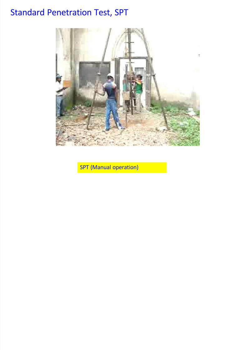
Standard Penetration Test, SPT

7/30/2019 Lecture-1 Shear Strength of Soils
http://slidepdf.com/reader/full/lecture-1-shear-strength-of-soils 91/97
SPT is the most widely used test procedure to determine the
properties of in-situ soils
63.5 kg
0.76 m
Drill rod
0.15 m
0.15 m0.15 m
Number of blows = N1
Number of blows = N2
Number of blows = N3
Standard penetration resistance (SPT N) = N2 + N3
Number of blows for the first 150 mm
penetration is disregarded due to the
disturbance likely to exist at the bottom of the
drill hole
The test can be conducted at every 1m vertical
intervals
Various correlations have been developed to determine soil
strength parameters (c, , ect) from N

7/30/2019 Lecture-1 Shear Strength of Soils
http://slidepdf.com/reader/full/lecture-1-shear-strength-of-soils 92/97
Standard Penetration Test, SPT
7/30/2019 Lecture-1 Shear Strength of Soils
http://slidepdf.com/reader/full/lecture-1-shear-strength-of-soils 93/97
SPT (Manual operation)
7/30/2019 Lecture-1 Shear Strength of Soils
http://slidepdf.com/reader/full/lecture-1-shear-strength-of-soils 94/97
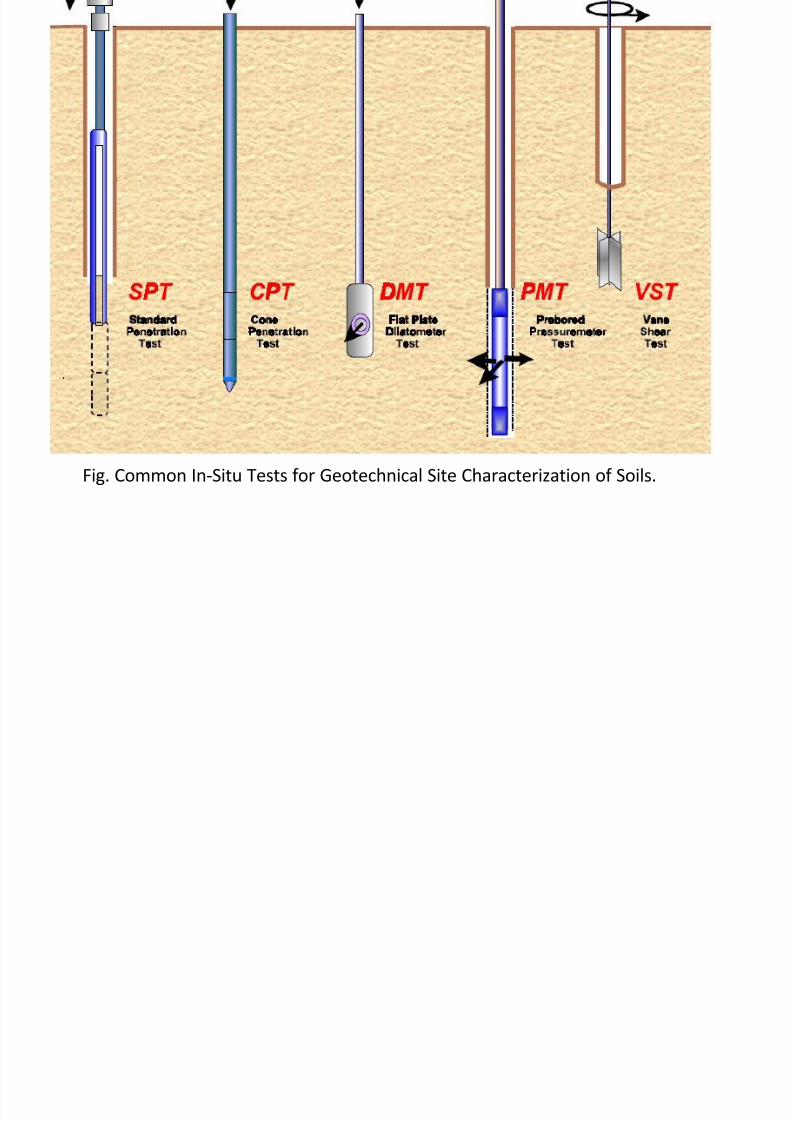
Fig. Common In-Situ Tests for Geotechnical Site Characterization of Soils.
Summary of chapter one

7/30/2019 Lecture-1 Shear Strength of Soils
http://slidepdf.com/reader/full/lecture-1-shear-strength-of-soils 95/97
Discuss shear strength parameters of soils.
What is the reason in case of soil thatgeotechnical structures such as shallow
foundation, pile foundation, retaining walls,
embankment dam and etc are failed?What is difference between positive pore water
pressure and negative pore water pressure?
Describe the methods used to determine shearstrength parameters of soils.
#2 assignment

7/30/2019 Lecture-1 Shear Strength of Soils
http://slidepdf.com/reader/full/lecture-1-shear-strength-of-soils 96/97
#2 assignment
1. Write short note on difference of laboratorytest and in-situ test for shear strength of soils,
and give your reason which is important/
better/ from both of tests method.
7/30/2019 Lecture-1 Shear Strength of Soils
http://slidepdf.com/reader/full/lecture-1-shear-strength-of-soils 97/97