lect7 - design for shear - avant-garde · pdf filedesign for shear university of wisconsin...
TRANSCRIPT
= =
Design For Shear
UNIVERSITY OF WISCONSIN STOUTCOLLEGE OF SCIENCE, TECHNOLOGY, ENGINEERING, AND MATHEMATICS
LECTURE VII
Dr. Jason E. Charalambides
Slabs Without Shear Reinforcement
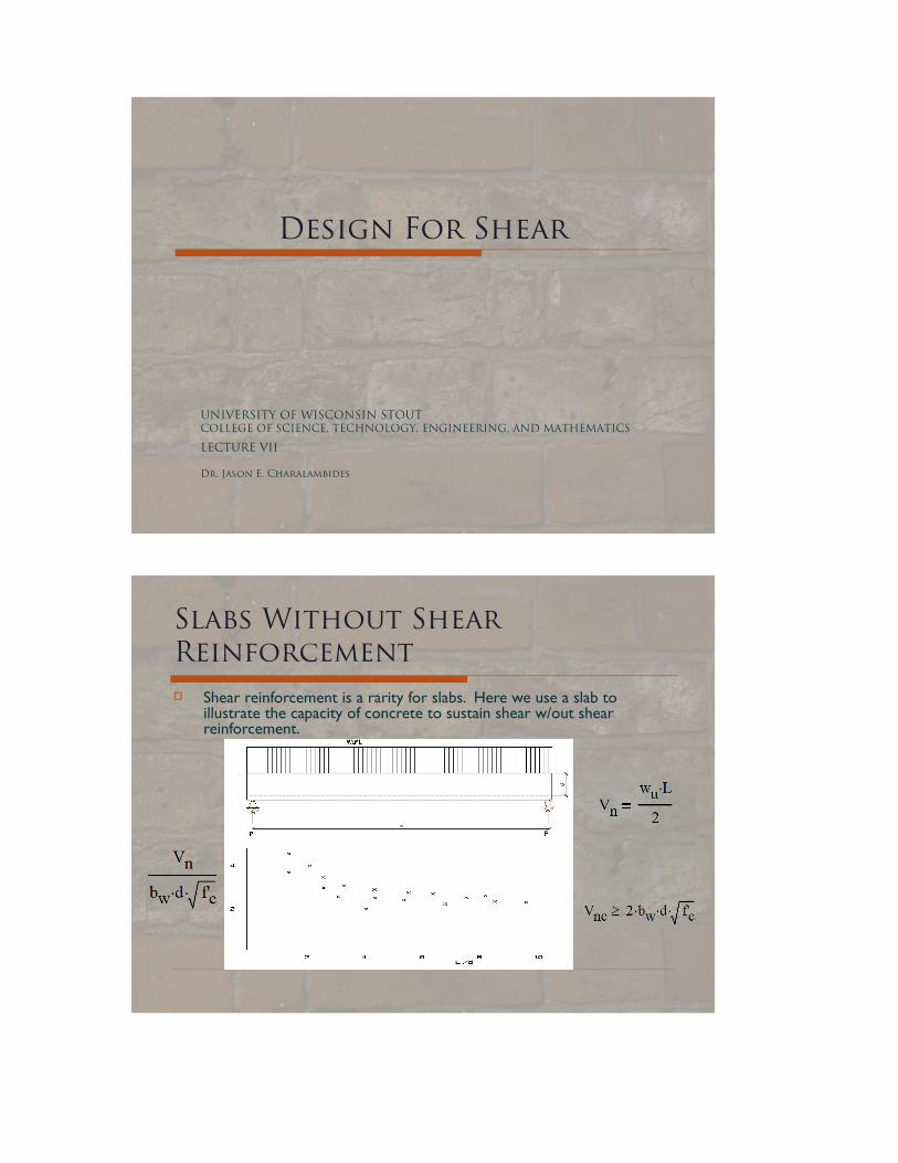
Shear reinforcement is a rarity for slabs. Here we use a slab to illustrate the capacity of concrete to sustain shear w/out shear reinforcement.

Slabs Without Shear Reinforcement
The chart represents test data from slabs reinforced for flexure only. The abscissa is the ratio L/d and the ordinates are values of the ratio between the limit shear Vn and the result of (bw*d*√f`c). The chart indicates that there is more shear capacity for the shorter rather than the longer spans of an element with same thickness and width. If spans are more than 4 to 6 times the depth of the slab, nominal shear strength of concrete can be given by the following formula:
Note: ACI318 (11.3.2.1) can yield a value gain of 5%-15% in regions near supports, but due to its relative complexity and the limited gain, it is not used frequently
Design For Shear Reinforcement When a shear failure mechanism is taken
along a crack at 45˚, the number of stirrups that will intercept the crack will be equivalent to the beam depth “d” divided by the spacing “s”. Thus the strength of stirrups as shear reinforcement becomes:
The capacity safety factor given by ACI section 9.3.2.3 is 0.75. (Appendix C2 gives safety factor 0.85). The total shear strength is the sum of the concrete shear strength and the dowel strength:

Design For Shear Reinforcement Shear reaches maximum at the points of support. If we can assume
that the support provides compression at the bottom of the beam, diagonal cracks will begin as flexural cracks (remember last lecture) at distance “d” or further from the points of support.
The actual shear force that will cause the diagonal crack will not be the shear at the face of the column, but the shear at that distance “d”.
Slabs and beams that are supported by elements deep enough (columns or deep beams) that can apply a compression force at their bottom side, may experience a crack no closer than distance “d” from the extreme fiber of that support.
For ACI, maximum design shear force is the shear applied at that distance “d”, where a 45˚ crack may lead toward the top of the beam. Stirrups need to be placed at the face of the support through the distance “d”.
Design For Shear Reinforcement
ACI requires that stirrups are used in all beams that experience shear values exceeding 0.5ΦVnc. Beams in which bw exceeds 2.5d and joists (conforming to
ACI318/8.11 definition of joist) are to be exempted from this basic design requirement for shear. In fact a 10% gain can be given to the strength of joists over the basic equation:
Design Stirrups For Shear Reinforcement
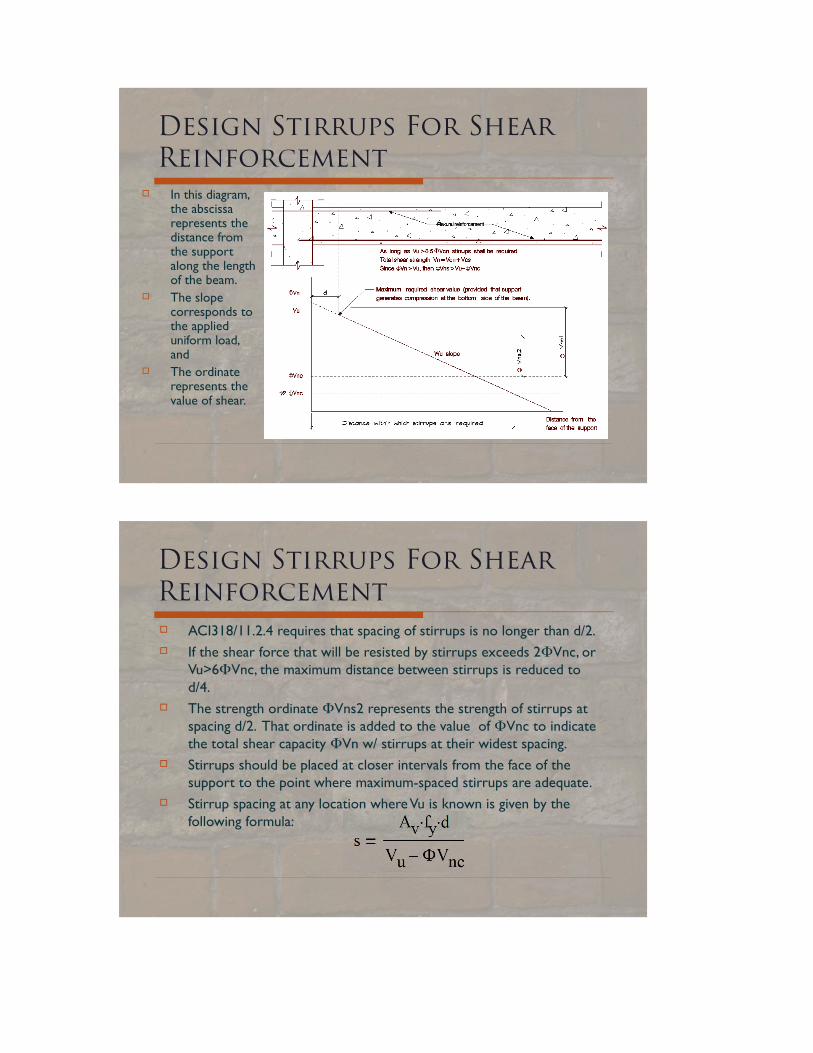
In this diagram, the abscissa represents the distance from the support along the length of the beam.
The slope corresponds to the applied uniform load, and
The ordinate represents the value of shear.
Design Stirrups For Shear Reinforcement ACI318/11.2.4 requires that spacing of stirrups is no longer than d/2. If the shear force that will be resisted by stirrups exceeds 2ΦVnc, or
Vu>6ΦVnc, the maximum distance between stirrups is reduced to d/4.
The strength ordinate ΦVns2 represents the strength of stirrups at spacing d/2. That ordinate is added to the value of ΦVnc to indicate the total shear capacity ΦVn w/ stirrups at their widest spacing.
Stirrups should be placed at closer intervals from the face of the support to the point where maximum-spaced stirrups are adequate.
Stirrup spacing at any location where Vu is known is given by the following formula:

Design Stirrups For Shear Reinforcement Let’s recall these stresses from the previous session:
Take a look at points 1 & 2. We can picture the action of the stirrups being in tension. At the same time, concrete acts as a compressive element along those diagonal lines. ACI318/11.5.6.8 limits the Vsn to 4Vcn, the stress value under which concrete diagonal struts fail in C. No additional stirrup reinforcement shall increase the shear strength after concrete struts fail.
Design Stirrups For Shear Reinforcement The designer should keep in mind the following index values of shear
strength:
Stirrups must be used whenever Vu exceeds (Φ√f`c)(bw*d)/2
Maximum spacing of stirrups is d/2 unless Vu exceeds (6Φ√f`c)(bw*d), above which maximum stirrup spacing is set to d/4
The section itself must be made larger if Vu exceeds (10Φ√f`c)(bw*d)
According to ACI318/11.5.5.3, where stirrups are required, the quantity Av/s must be greater than (.75√f`c)*(bw/fy)>50(bw/fy).
This clause that is intended to assure stirrups shall not yield after a shear crack develops as they pin together, and it may reduce the spacing “s” of stirrups to less than d/2 if beams are large or wide.

Design Stirrups For Shear Reinforcement
Deep and thin beams may not develop their potential Vcn=(2ef`c)(bw/fy).
Beams deeper than four times their length should contain horizontal shear reinforcement in addition to vertical bars.
The design of shear reinforcement requires selection of stirrup size and determination of spacing needed to resist shear. Stirrups size is related to beam size. If bw*d<450 sq. in, #3 dowels shall suffice. Dowels of #4 or #5 should be used for larger cross sectional areas.
To determine stirrups as shear reinforcement, it is recommended that a diagram is constructed. With abscissa as length and ordinates as shear strength, horizontal lines at the values of 0.5ΦVnc, ΦVnc, ΦVn, and a vertical line at distance “d” will aid in the process.
Design Stirrups For Shear Reinforcement Let’s take a look at some simple formulas that are ACI requirements, based on
what we just talked about:

In Class Example (intro):
Steel Grade is 60, f`c=4ksi, bw=20in, d=19.5", L=26`, Construct a Shear strength diagram.
In Class Example cont:
Deep Beams
The definition of “deep beams” refers to beams that have a length/depth ratio higher than 4 or they assume a significant concentrated load at a location two times the member’s depth from the support.
For deep beams shear reinforcement must incorporate horizontal as well as vertical re-bars.
Concrete compressed as a shear strut must be “confined” laterally by reinforcement with a density Avi*(sinγ)/bsi in each direction such that the sum of both densities exceeds the quantity 0.003. The diagonal angle γ is taken w/ respect to the bar (horizontal or vertical).
The compression strut area Acs has a width b and a depth that may be considered to increase at a rate equal to the distance along the strut from the center of the nodal point.
The strength of the concrete struts is 0.85*f`c*Acs. Also, CCC nodal points at intersection of 3 struts must possess the same
compression strength limit of 80% or 0.65f`cAcs. The value φ=0.75 applies for shear.
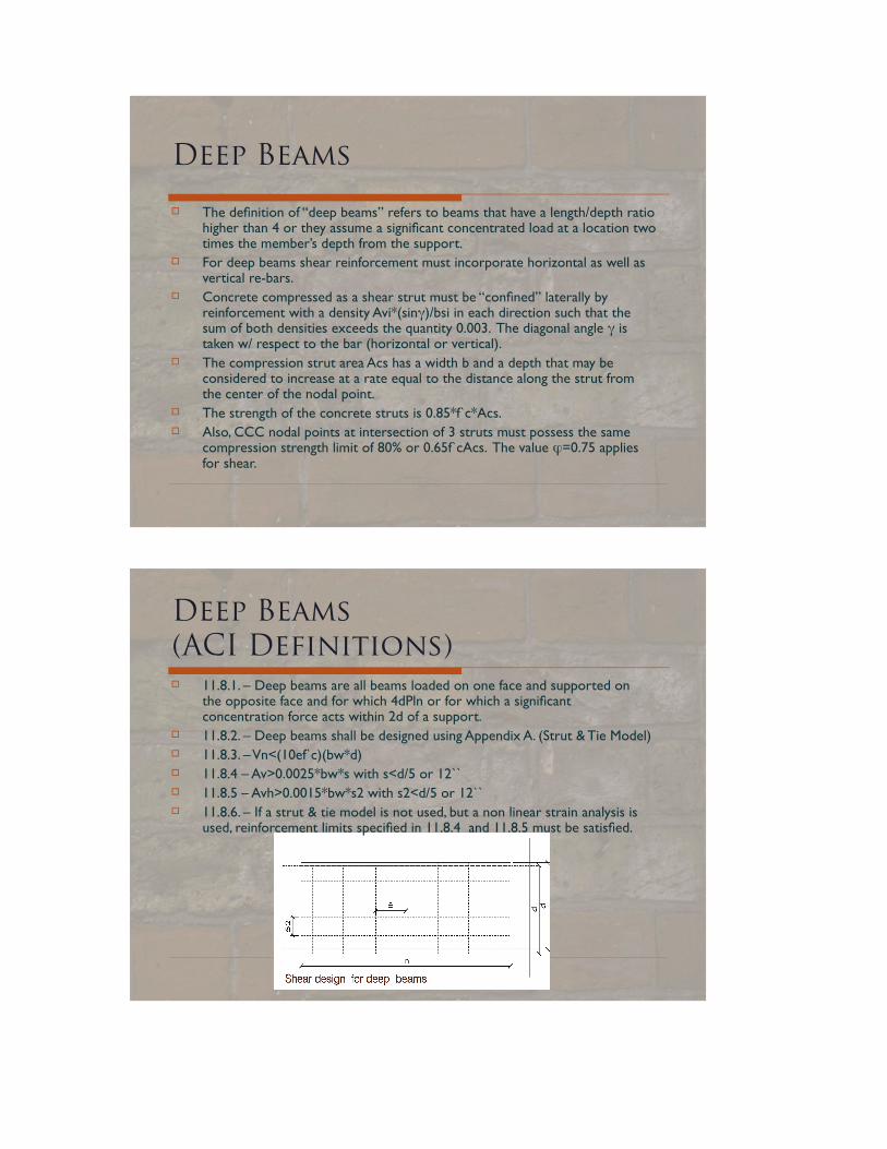
Deep Beams(ACI Definitions) 11.8.1. – Deep beams are all beams loaded on one face and supported on
the opposite face and for which 4dPln or for which a significant concentration force acts within 2d of a support.
11.8.2. – Deep beams shall be designed using Appendix A. (Strut & Tie Model) 11.8.3. – Vn<(10ef`c)(bw*d) 11.8.4 – Av>0.0025*bw*s with s<d/5 or 12`` 11.8.5 – Avh>0.0015*bw*s2 with s2<d/5 or 12`` 11.8.6. – If a strut & tie model is not used, but a non linear strain analysis is
used, reinforcement limits specified in 11.8.4 and 11.8.5 must be satisfied.

In Class Example:
In Class Example:
Corbel Design
Not covered in class.
Shear Combined With Torsion
Not covered in class.

RÉ~ÇáåÖ
Reading: Required:
Furlong Chapter 6 Recommended:
McCormac & Nelson, Chapter 8 for this week’s lectures.
^ppfdkjbkq
Assignments will be received at the beginning of class period.
Assignment 6 is due next session (not in a week for this time.)

Clarification On Textbook
Q: You state that d/2 is the maximum spacing and it becomes d/4 if our Vu is larger than 6*Φ*√f`c*(bw*d). Could you please verify this?
A: The text you quoted is correct. When stress V/ bw*d exceeds 4√fc', spacing must be less than d/2. Thus when Vu /(bw*d) exceeds Vc plus 4 Vs it exceeds 6√fc'.