lec 6 and 7 electrostatic
TRANSCRIPT

7/22/2019 LEC 6 and 7 Electrostatic
http://slidepdf.com/reader/full/lec-6-and-7-electrostatic 1/33
Electrostatic Actuation andDetection
Department of M echanical Engineer ing
Sherry Towfighian
ME521 Dynamics of MEMS

7/22/2019 LEC 6 and 7 Electrostatic
http://slidepdf.com/reader/full/lec-6-and-7-electrostatic 2/33
Mohammad Younis MEMS ModelingMohammad Younis MEMS Modeling2
Electrostatic Transduction
It is the most common actuation and sensing method in MEMS
because of its simplicity and high efficiency.
It relies on simple capacitors of parallel plate electrodes. These can
be easily fabricated using surface micromachining.
It does not require any special material, deposition of any patches,
or any external field sources. It only requires a voltage source.
Two classical MEMS devices :
-The Analog Devices accelerometers
for airbag deployments,which use capacitive detection.
-The digital mirror display DMD
for projection displays
by TI, which relies on electrostatic actuation.

7/22/2019 LEC 6 and 7 Electrostatic
http://slidepdf.com/reader/full/lec-6-and-7-electrostatic 3/33
Mohammad Younis MEMS ModelingMohammad Younis MEMS Modeling3
Features
It is characterized by very low power consumption (parallel-plate
capacitor is an open-circuit component).
Electrostatic actuation offers high energy density, high mechanical
flexibility, and well controlled force. Also, it is considered fast actuation method.
In electrostatic sensing, a physical quantity, such as acceleration,
changes the capacitance values of the parallel-plate capacitor,
which can be related to the physical quantity being measured.

7/22/2019 LEC 6 and 7 Electrostatic
http://slidepdf.com/reader/full/lec-6-and-7-electrostatic 4/33
Mohammad Younis MEMS ModelingMohammad Younis MEMS Modeling4
Disadvantages
•Its main disadvantages is the nonlinearity, especially for out-of-
plane capacitors. This limits the controlled travel range of actuators
and can result in unexpected collapse and functional failure of
sensors.
•Also, the large driving voltage for actuation applications, such as
in RF switches, is another limitation.

7/22/2019 LEC 6 and 7 Electrostatic
http://slidepdf.com/reader/full/lec-6-and-7-electrostatic 5/33
Mohammad Younis MEMS ModelingMohammad Younis MEMS Modeling5
Parallel-Plate Capacitor
The most common forms of electrostatic sensing and actuation are
based on either simple parallel-plate capacitors or comb-drive
configuration of multiple interdigitated or non-interdigitated fingers.
Parallel-plate capacitor derivations:
Assume infinite plates (negligible fringe effect).
Because of the power source, the capacitor
is charged according to
where Q is the electrical charge, C is capacitanceand is a variable representing the degree of
freedom of the moveable electrode of the capacitor.
d
V
Stationary
Moveable
( )Q C V

7/22/2019 LEC 6 and 7 Electrostatic
http://slidepdf.com/reader/full/lec-6-and-7-electrostatic 6/33
Mohammad Younis MEMS ModelingMohammad Younis MEMS Modeling 6
Parallel-Plate Derivations
The potential energy E c stored in the capacitor can be expressed as
The initial energy of the battery that is hooked-up to the capacitor
is assumed to be E 0. When connected to the capacitor, the battery provides the electrical
charge Q and an electrical potential – QV , which is negative since it
is lost from the battery. Hence the new potential energy of the
battery E b is reduced to
The total potential energy E is equal to that from the battery and the
capacitor, that is
21( )
2c E C V
20 0b E E QV E CV
2 2 2
0 0
1 1
2 2b c E E E E CV CV E CV

7/22/2019 LEC 6 and 7 Electrostatic
http://slidepdf.com/reader/full/lec-6-and-7-electrostatic 7/33Mohammad Younis MEMS ModelingMohammad Younis MEMS Modeling7
Parallel-Plate Force
The attractive force F between the two electrodes of the capacitor
can be obtained according to
For electrodes of simple geometries, an analytical expression can
be found for C .
For electrodes of complicated geometry, finite-element or
boundary-element analysis can be used to characterize the
dependence of C on the displacement . Then, curve fitting is
used to extract a simple analytical expression for that can be
used in Eq. (*) .
2( ) 1 ( ) (*)
2
E C F V
( )C
Si l ll l l l

7/22/2019 LEC 6 and 7 Electrostatic
http://slidepdf.com/reader/full/lec-6-and-7-electrostatic 8/33Mohammad Younis MEMS ModelingMohammad Younis MEMS Modeling8
Simple Parallel-Plate Rectangular
Capacitors
C ( x) above is obtained by solving
the Laplace equation of the electrostatic
potential between the two rectangular plates.
A is the overlap area between the two electrodes ( A=Lb), is the
relative permittivity of the gap space medium with respect to the free
space (equal unity in air), and is the dielectric constant in free
space, .
Substituting for C ( x)into Eq. (*) yields
Minus: Attractive force, opposite to x direction.
Fixed Moveable
b L
-
+
x
t x
( ) r o r o
A LbC x
x x
2
2 (**)
2
r o AV F
x
o
r
12 2 28.85 10 ( / )o C Nm

7/22/2019 LEC 6 and 7 Electrostatic
http://slidepdf.com/reader/full/lec-6-and-7-electrostatic 9/33Mohammad Younis MEMS ModelingMohammad Younis MEMS Modeling9
Pull in
Note from Eq. (**) that the parallel-plate electrostatic force is inherently
nonlinear in terms of the electrodes separation. Typically in MEMS, the movable electrode is a flexible structure, such as
a beam or a plate. Hence, when deflected with a distance x due to the
electrostatic force, the resorting force of the structure tends to oppose the
electrostatic force (acts as a spring). If the electrostatic force is not too
big, equilibrium between the restoring and electrostatic force is achieved.
However, if the voltage load is increased too much, then the electrostatic
force overcomes the resorting force of structure leading to its collapse,
where it hits the stationary electrode. This phenomenon is known in
electrostatic MEMS as the pull-in instability.
VDCVDC VDCVDCVDCVDCVDC VDCVDC
(a) V DC =0 (b) V DC < V pull-in (c)V DC > V pull-in

7/22/2019 LEC 6 and 7 Electrostatic
http://slidepdf.com/reader/full/lec-6-and-7-electrostatic 10/33Mohammad Younis MEMS ModelingMohammad Younis MEMS Modeling10
Electrostatic Sensing
In sensing application, pull-in is undesirable. It leads to short
circuit, stiction, and un-functionality of the sensor.
Diaphragm
Pressure
VLower electrode
Diaphragm Upper electrodeLower electrode
(a) Taken apart. (b) Assembled.
(c) Schematic.
Cantilever beamsAttachment point
(a) Taken apart. (b) Assembled.
Proof mass
(upper electrode)
VLowe electrode
motion
(c) Schematic.
Accelerometer. Pressure sensor.
(Sensata Technologies)

7/22/2019 LEC 6 and 7 Electrostatic
http://slidepdf.com/reader/full/lec-6-and-7-electrostatic 11/33Mohammad Younis MEMS ModelingMohammad Younis MEMS Modeling11
Electrostatic Actuation
Many actuators rely on pull-in to achieve reliable actuation in short
time. RF switches and micro-relays use this actuation method. RF
switches are commonly used for wireless, communications, and radar
applications. Pull-in provides fast actuation method with large stroke. Another example is the actuation of the Deformable Mirror Device
DMD or the micromirror of Texas Instruments. The micromirroir is
actuated beyond pull-in in angular motion to deflect and reflect
incident lights .
V
V
Switch “On”
Switch “Off”
Gate Drain
Micromirror
VVActuation padLanding pad

7/22/2019 LEC 6 and 7 Electrostatic
http://slidepdf.com/reader/full/lec-6-and-7-electrostatic 12/33Mohammad Younis MEMS ModelingMohammad Younis MEMS Modeling12
Pull-in Model
The above represents a model for a parallel-plate capacitor, where
the moveable electrode of mass m is a flexible structure, such as a
beam, of stiffness k , which forms the upper electrode.
k
x
m
d V DC
m
kx
2
22( )
r o AV F d x
2
2
2( )
AV F
d x
2
2 (1)
2( )
AV kx
d x
Equilibriumr o

7/22/2019 LEC 6 and 7 Electrostatic
http://slidepdf.com/reader/full/lec-6-and-7-electrostatic 13/33Mohammad Younis MEMS ModelingMohammad Younis MEMS Modeling13
Pull-in Model
Equation (1) is a cubic equation in x with three possible
solutions:
(a) One predicts x>d , and hence it is nonphysical and discarded.
(b)One represents unstable solution, meaning that practically the
structure cannot hold into it.
(c)One solution ( x<d ) that is stable, which represents the “real”
deflection of the upper electrode in response to the DC load. It
is smaller than (b).
One easy approach to explore the solutions of Eq. (1) is to
plot the right-hand and left-hand sides of the equation and
then look for their intersection.
2
2 (1)2( )
AV
kx d x

7/22/2019 LEC 6 and 7 Electrostatic
http://slidepdf.com/reader/full/lec-6-and-7-electrostatic 14/33Mohammad Younis MEMS ModelingMohammad Younis MEMS Modeling14
Pull-in Expression
Note that at V DC = V pull , x=d/3 .
0 0.5 10
0.2
0.4
0.6
0.8
1
F o r c e / ( k
d )
x/d 0 0.5 1
0
0.2
0.4
0.6
0.8
1
F o r c e
/ ( k d )
x/d
0 0.5 10
0.2
0.4
0.6
0.8
1
F o r c e / ( k d )
x/d
d/3
0 0.5 10
0.2
0.4
0.6
0.8
1
F o r c e
/ ( k d )
x/d
(a) V DC << V pull . (b) V DC < V pull .
(c) V DC = V pull . (d) V DC > V pull .
38
27 pull
kd V
A
Subst. in Eq. (1), solve for V

7/22/2019 LEC 6 and 7 Electrostatic
http://slidepdf.com/reader/full/lec-6-and-7-electrostatic 15/33Mohammad Younis MEMS ModelingMohammad Younis MEMS Modeling 15
Pull-in Plot
Another way to view the solution of Eq. (1) is to solve for V in terms
of x as One can then plot this equation for several values of x.
Of the two curves, the smaller one represents stable solutions and
the larger one represents unstable solutions. Both meet at the pull-in.
22 ( ) / ( ) DC V kx d x A
0.2 0.4 0.6 0.8 1.0
x
d
0.2
0.4
0.6
0.8
1.0
V DC
V pull
2
2 (1)2( )
AV
kx d x
T i l A t t d

7/22/2019 LEC 6 and 7 Electrostatic
http://slidepdf.com/reader/full/lec-6-and-7-electrostatic 16/33Mohammad Younis MEMS ModelingMohammad Younis MEMS Modeling 16
Torsional Actuators and
Micromirrors
Electrostatically actuated torsional micromirrors form the backbone of
the technology of video and image projections and flat-screen TV’s of
Texas Instrument (www.dlp.com).
Each mirror, also called Deformable Mirror Device DMD, representsone image pixel on the chip. The chip contains approximately two
million of these. The mirror reflects the incident light thousands of tim
per second in a digital on-off fashion.
The mirror is brought to the on position by actuating it beyond pull-in.

7/22/2019 LEC 6 and 7 Electrostatic
http://slidepdf.com/reader/full/lec-6-and-7-electrostatic 17/33Mohammad Younis MEMS ModelingMohammad Younis MEMS Modeling
17
Modeling Torsional Actuators
Electrostatic force on a small segment.
V DC
a3
x
a2
d
t
a1
dx
a1
b
w
t
a3
a2
Electrode
l
2
22( )
bV dxdF
d x
2 2
1 1
2
22( )
a a
DC e
a a
bV x M xdF dxd x
2
2
2
2 1 1
ln2
DC e
bV d ad d M
d a d a d a
Electrostatic torque

7/22/2019 LEC 6 and 7 Electrostatic
http://slidepdf.com/reader/full/lec-6-and-7-electrostatic 18/33Mohammad Younis MEMS ModelingMohammad Younis MEMS Modeling
18
Modeling Torsional Actuators
A more convenient form of the electrostatic torque can be obtained
by normalizing with respect to its maximum possible value
and defining
max 3/d a
max
;
1 2
3 3
;a a
a a
2
2 2
max
1 1 1ln
2 1 1 1 DC
e
bV M
In the special case that the electrode spans the whole length of the
actuator a1= =0 , a2 = a3 and =1. Then
2
2 2
max
ln 12 1
e
bV M

7/22/2019 LEC 6 and 7 Electrostatic
http://slidepdf.com/reader/full/lec-6-and-7-electrostatic 19/33Mohammad Younis MEMS ModelingMohammad Younis MEMS Modeling
19
Modeling Torsional Actuators
When an electrostatic torque is applied on the upper plate of the
actuator, an opposing restoring torque M mech from the torsional
springs is induced to counter this torque:
where K t is the effective torsional spring coefficient of the two
torsional springs. Thus, the actuator reaches an equilibrium state at
the tilted angle . The equation of equilibrium can be written as
Each side of Eq. (2) can be plotted for a given voltage.
Alternatively, an expression for V can be solved:
maxmech t t M K K
2
max 2 2
max
1 1 1ln (2)
2 1 1 1
DC t
bV K
3 3
max2
1 1 1ln1 1 1
t DC
K V
b

7/22/2019 LEC 6 and 7 Electrostatic
http://slidepdf.com/reader/full/lec-6-and-7-electrostatic 20/33Mohammad Younis MEMS ModelingMohammad Younis MEMS Modeling
20
Torsional Pull-in
For the special case of a full-electrode actuator, pull-in occurs at
More generally, it occurs at
The pull-in voltage can be calculated according to
For the special case of a full-electrode actuator:
0.4404
1 22.117
0.4404; /
1 0.322
pull a a
3
0.32442 0.5 1.931
3
2
0.8275(1 ) 1 0.6735t
pull
K d V
ba
3
3
2
0.90967 t pull
K d V
ba

7/22/2019 LEC 6 and 7 Electrostatic
http://slidepdf.com/reader/full/lec-6-and-7-electrostatic 21/33Mohammad Younis MEMS ModelingMohammad Younis MEMS Modeling
21
Example
Consider the torsional actuator of the parameters in the table below.
Evaluate the normalized angle for V DC
=12 V
Plot V DC versus .
Calculate V pull and analytically and compare to the plot.
K t 310 (N. m) a1 ( m ) a2 ( m ) a3 ( m ) d ( m ) b ( m )
0.0143087 430 580 600 3.42 1300
pull
V DC
a3
x
a2
d
t
a1
dx
a1
b
w
t
a3
a2
Electrode
l

7/22/2019 LEC 6 and 7 Electrostatic
http://slidepdf.com/reader/full/lec-6-and-7-electrostatic 22/33Mohammad Younis MEMS ModelingMohammad Younis MEMS Modeling
22
Example Solution
First, we plot both sides of Eq. (2) to show the intersection of the
curves and the two possible solutions. Using the command
“FindRoot” in the software Mathematica with an initial guess from
the figure gives
Using the analytical expressions gives
0.2 0.4 0.6 0.8
0.2
0.4
0.6
0.8
1.0
1.2
1.4
Torques K t max
0.2 0.4 0.6 0.8 1.0
5
10
15
20V DC V
0.075064
0.376 pull
19.5 V pull V
2
max 2 2
max
1 1 1ln (2)
2 1 1 1 DC
t
bV K

7/22/2019 LEC 6 and 7 Electrostatic
http://slidepdf.com/reader/full/lec-6-and-7-electrostatic 23/33
Mohammad Younis MEMS ModelingMohammad Younis MEMS Modeling23
Comb-Drive Devices
They are commonly used in MEMS for sensing and actuation. They have
been implemented in accelerometers, microgrippers, resonators, filters, andgeneric force actuators.
Comb-drive devices rely on two comb structures, a stationary and a
moveable one that is connected to flexible structures (springs or tethers).
The flexible structures are made to be compliant in the direction of the
desirable displacement and stiff in the orthogonal directions to limit motion
in these directions.
Each comb consists of interdigitated fingers. The stationary and moveable
fingers form parallel-plate
capacitors among each other.

7/22/2019 LEC 6 and 7 Electrostatic
http://slidepdf.com/reader/full/lec-6-and-7-electrostatic 24/33
Mohammad Younis MEMS ModelingMohammad Younis MEMS Modeling24
Comb-Drive Types
Comb-drive devices can have many configurations, such as rotary, out-of-
plane, and in-plane devices. The most common are the in-plane devices.
In-plane devices can be classified into two categories: transverse and
longitudinal. In either case, each moveable finger is sandwiched between
two fixed fingers, where portion of its surface overlap with those of the fixed
fingers. This causes capacitive and electrostatic interaction among thefingers resulting in an actuation and/or detection mechanism.
y x
z
d
l g
t
b

7/22/2019 LEC 6 and 7 Electrostatic
http://slidepdf.com/reader/full/lec-6-and-7-electrostatic 25/33
Mohammad Younis MEMS ModelingMohammad Younis MEMS Modeling25
Transverse Comb-Drive
The moveable comb moves in transverse direction to the longitudinalaxis of the fingers (along the x-axis in the figure). As seen in the
figure, the moveable finger represents an electrode for two parallel-
plate capacitors with two stationary fingers, thereby forming one
capacitor to its right and another one to its left.
y
x
z
Fixed electrode
Fixed electrode
Moveable electrode
Anchors
Tether(spring)
Tether

7/22/2019 LEC 6 and 7 Electrostatic
http://slidepdf.com/reader/full/lec-6-and-7-electrostatic 26/33
Mohammad Younis MEMS ModelingMohammad Younis MEMS Modeling26
Transverse Comb-Drive Force
If the finger moves a positive distance x (to the left), then the
capacitance of the left capacitor C left
and right capacitor C right
are
expressed as
y x
z
d
l g
t
b
( );
( );
left
right
lt C
g x
lt C
g x

7/22/2019 LEC 6 and 7 Electrostatic
http://slidepdf.com/reader/full/lec-6-and-7-electrostatic 27/33
Mohammad Younis MEMS ModelingMohammad Younis MEMS Modeling 27
Transverse Comb-Drive Force
Note that in the case of no displacement, x=0, and C left = C right .
Otherwise,
This differential capacitance can be used to sense the motion of the
moveable comb. To increase the value of the induced capacitance,
the number of comb fingers is increased.
If the capacitors are biased by a voltage V , then two electrostatic
forces will be generated on the moveable finger:
If x=0, the electrostatic forces acting on the
moveable finger cancel each other. Otherwise a
resultant force F right -F left will act on the
moveable finger.
This represents the backbone of the ADXL-50 accelerometer of Analog Devices.
2 2
2 ( )left right
lt xC C
g x
2
2
2
2
( );
2
( );
2
left
right
lt V F
g x
lt V F
g x

7/22/2019 LEC 6 and 7 Electrostatic
http://slidepdf.com/reader/full/lec-6-and-7-electrostatic 28/33
Mohammad Younis MEMS ModelingMohammad Younis MEMS Modeling28
The ADXL-50 Accelerometer of Analog Devices

7/22/2019 LEC 6 and 7 Electrostatic
http://slidepdf.com/reader/full/lec-6-and-7-electrostatic 29/33
Mohammad Younis MEMS ModelingMohammad Younis MEMS Modeling29
Longitudinal Comb-Drive
In the case of a longitudinal comb-drive, the moveable comb moves
parallel to the longitudinal axis of the fingers (along the y-axis).
V
Moveable Electrode x
y b
z
t
d Fixed
Fixed electrode
Fixed electrode
Moveable electrode
y
x z
Tether Tether
7/22/2019 LEC 6 and 7 Electrostatic
http://slidepdf.com/reader/full/lec-6-and-7-electrostatic 30/33
Mohammad Younis MEMS ModelingMohammad Younis MEMS Modeling30
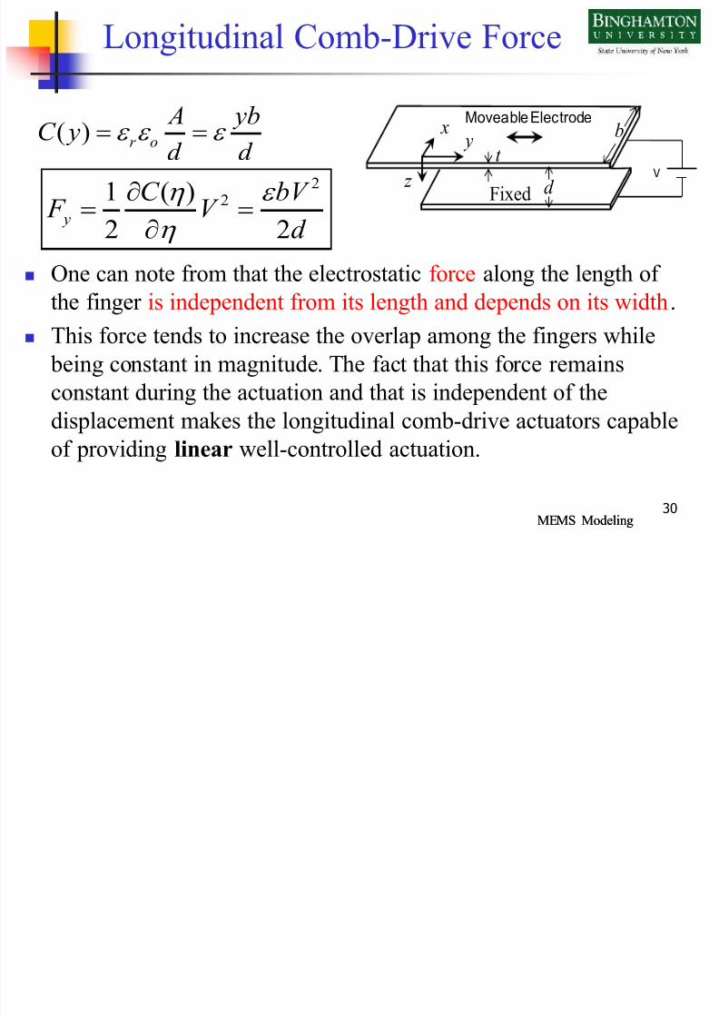
Longitudinal Comb-Drive Force
One can note from that the electrostatic force along the length of
the finger is independent from its length and depends on its width.
This force tends to increase the overlap among the fingers while
being constant in magnitude. The fact that this force remains
constant during the actuation and that is independent of the
displacement makes the longitudinal comb-drive actuators capable
of providing linear well-controlled actuation.
( ) r o A ybC yd d
V
Moveable Electrode
x y b
z
t
d Fixed2
21 ( )
2 2 y
C bV F V
d

7/22/2019 LEC 6 and 7 Electrostatic
http://slidepdf.com/reader/full/lec-6-and-7-electrostatic 31/33
Mohammad Younis MEMS ModelingMohammad Younis MEMS Modeling31
Longitudinal Array
For the case of a longitudinal moveable finger sandwiched between
two stationary fingers, there are two capacitive forces generated on
the moveable finger from the two nearby stationary electrodes with
the electrode area of each capacitor is ty and the gap width g . For n
number of moveable fingers, the total electrostatic force acting on
the moveable comb drive is
y x
z
d
l g
t
b
2 2
2
2
Tot
y
tV n tV F n
g g

7/22/2019 LEC 6 and 7 Electrostatic
http://slidepdf.com/reader/full/lec-6-and-7-electrostatic 32/33
Mohammad Younis MEMS ModelingMohammad Younis MEMS Modeling32
Example
Example: A comb-drive actuator has 10 moveable fingers with t=2 µm and g=2 µm. The stiffness of the tethers holding the moveable
comb was measured and found to be k=0.01 N/m. Calculate and plot
the deflection of the comb when actuated by a voltage load ranging
from 0-10 V .
Solution:
It is clear from that the deflection is linearly proportional to the
voltage squared and to the electrostatic force. This is unlike the case
of parallel-plate capacitive actuation, where the deflection and force
are related nonlinearly
2
n tV ky g
2 1 Tot
y
n tV y F
kg k

7/22/2019 LEC 6 and 7 Electrostatic
http://slidepdf.com/reader/full/lec-6-and-7-electrostatic 33/33
33
Example
0 2 4 6 8 100
0.1
0.2
0.3
0.4
0.5
0.6
0.7
0.8
0.9
Voltage (V)
Displacement(
m)