learning to code - with a purpose part 2 adrian oldknow … · learning to code - with a purpose...
TRANSCRIPT

Learning to code - with a purpose Part 2 Adrian Oldknow Jan 2015 [email protected]
My motivation for embarking on this voyage is for me, and I hope you as well, to gain a better understanding of the devices and systems which have been developed in our lifetime following the discoveries about semiconductors in 1948 and the subsequent development of first transistors and then Integrated Circuits (ICs = the Chip). One very familiar example is in the storage of data, where we now take for granted cheap `flash’ memory cards in our phones, cameras and computers. Each year sees more memory for less money in a smaller package. These are just one factor in how, in an incredibly short period of time, mobile phones (and similar devices) have become commonplace tools used universally. Not surprisingly, then, many of us have been left behind by the pace of such technological advances and have just a scant idea of how they work or are capable of being used to full capacity. The encouraging thing, for a patriotic Brit like me, is the extent to which the UK has contributed to such developments – and will continue to do if we can inspire the next generation to pick up the flame and run with it. Before getting back to brass tacks I will mention just a few examples of these contributions which underpin the iPhone!
Processors The Acorn Computer Ltd was founded in Cambridge in 1979 by Hermann Hauser and Chris Curry. It developed the BBC Computer in the 1980s around a commonly used microprocessor called the 6502. In order to improve performance Acorn engineers studied which operations were performed most frequently and developed their own Reduced Instruction Set Computer design for a new RISC microprocessor. This was the start of the Acorn RISC Machines which were the seeds from which ARM Holdings has become the world leader in processors for mobile devices: http://www.arm.com/.
Communication In order to send messages securely over long distances, they have to be encoded. This uses results from a branch of pure mathematics called `cryptography’. We now know about the advances made by Alan Turing and others at Bletchley Park decoding German ciphers during WWII. Less well known is the role played by Clifford Cox and colleagues at GCHQ in encoding military information in the 1970s http://www.bbc.co.uk/news/uk-england-gloucestershire-11475101. This led to the development of encrypted secure communication for mobile phones by Henry Beker at Racal – and now for secure communication over the Internet: http://www.independent.co.uk/news/business/zergo-becomes-a-leader-in-net-commerce-1191952.html.
Design Performance is not the only factor in producing a successful consumer product, such as the iPhone. It needs to look and feel good, as well as being easy to use. Since 1996 the Chief Designer at Apple has been Sir Jonathan (Jony) Ive: https://www.apple.com/uk/pr/bios/jonathan-ive.html. His father, Mike, was a DT teacher who became an HMI. Jony took an Engineering Design course before joining Apple in 1992 and designing the iconic iMac computer. The rest is history! http://www.vogue.com/1415025/apple-
design-genius-jonathan-ive/. Graphics A key part of the appeal of mobile devices, such as tablets, is their high-definition
colour display – which requires a large amount of memory and a very high-speed controller to keep working. The UK world leader in this area is called Imagination Technologies in Herts. This was set up by Hossein Yassaie and powers the graphics in the iPhone: http://www.independent.co.uk/news/people/profiles/hossein-
yassaie-meet-the-man-with-the-big-imagination-8160782.html.
I finished off the first part of this personal tour through programming with a résumé.
8. Résumé The word “coding” is often misused. Whether you write your programs in Scratch, Crumble, Robotiky, Arduino IDE, Ardublock, Javascript, C, C+, C++, C# or Python really doesn’t matter. The key skill is designing the program logic (aka `algorithm’) to solve the problem you have posed. In all but the simplest cases, this is likely to be an iterative process of `trial and improvement’. Tackling physical challenges involving `sense and response’ is very powerful way to develop your programming skills, as well as helping you to understand the way in which so many of the devices we take for granted nowadays actually work. Now we will look more into some of the extensions I am continuing to explore. Most of these, like Robotiky and Crumble, use pretty cheap UK designed products with good support.

9. Genie This is an educational project from New Wave Concepts based on their range of low cost microcontrollers with 8, 14, 20 or 28 pins: http://www.genieonline.com/. The basic starter Genie microcontroller kits cost from just £3.76 plus VAT & pp: http://www.rapidonline.com/electronic-components/geni e-8-pin-
microcontroller-system-kits-82991. You will need a special USB to stereo cable to connect your PC to a board costing £13.41: http://www.rapidonline.com/electronic-components/genie-usb-download-cable-501700. You will also need 3 AA batteries, a soldering iron, some solder, long nose pliers and probably a `helping hands’ stand such as: http://www.maplin.co.uk/p/helping-hands-with-magnifier-n30ch. You will also need to download and install the free educational version of the powerful flowchart-based language called Genie Design Studio: http://www.genieonline.com/ . Download the instruction sheets for your kit from e.g.: http://data.genieonline.com/resources/f108.pdf and the cable from: http://data.genieonline.com/resources/g110.pdf .
I have to confess it is a long while since I last did any soldering but the instructions are very clear. You just push the components, like an LED or resistor through the clearly labelled holes on the top (brown) side of the board, solder the connection on the back of the board and snip off any loose wire. You can see that we have 3 outputs – a red LED, a green LED and a buzzer. There are 2 inputs – a push button and a light-dependent resistor. The black 8 legged microcontroller plugs into a holder which you solder to the board. With the battery pack attached all you need to do is connect the board to the PC through the stereo connector you soldered to the board.

Now you can write your program in Genie Design Studio using its flowcharting interface. Start a New program and use the Gallery tab on the right to drag in the symbols such as Start, High, Low, Digital and Analogue. In my example I have made two programs which will run in parallel – impressive? The program on the left senses the state of the digital input – the button attached to the digital input G3. Double click the purple diamond for the Digital test block and enter information for the pin number and caption. Similarly double click on the blue parallelogram for the High block and set the pin and caption. If you want it to stay high for a fixed time then click the `Add wait’ box and set the time interval. Do the same for the Low block.
Now you drag wires from top, bottom and/or sides of the blocks to build the flowchart on the left. Basically this now says – “repeatedly test the press button and if it is high turn the green LED on, otherwise turn it off”. Something you could easily also write in Scratch, blocks (Crumble, Robotiky, Ardublock..) or the IDE. Now build the parallel program to control the red LED with the light-dependent resistor. I am using a small torch to control the amount of light. One of the options in the Program tab is to `calibrate a sensor’. So I can see that in the ambient light I am working in, that value read by the light sensor is currently 185. When I shine the torch on the resistor, this rises to around 240. So now I can fix the Analogue threshold. Finish off the right hand flowchart so that it says – “repeatedly test the light sensor and if it is above the threshold of 230 turn the red LED on, otherwise turn it off.” If you now run the program using the Program tab it will run both programs in parallel so you can see how the button controls the green LED while the light detector controls the red LED independently. Among the many kits and components available for use with Genie are motor packs – so you can build your own robots and program them from scratch. Using New Wave’s Circuit Wizard software you can also design and test your own circuits and boards. With the professional version of the Design Studio software you can also program using a version of Basic and switch between this and flowcharting mode. 10. PICAXE Microbot By now we have seen a number of different approaches to building the code for our sense-response devices as well as a number of different approaches to hardware design for us to experiment with. The next item on the menu is a very sophisticated system developed by Revolution Education in Bath. They have a range of microcontrollers and kits to go with them. I have chosen the PICAXE 20XC2 Microbot as a cheap entry-level ready-to-make kit. It costs £35 + VAT + pp = £48.60 from: http://www.picaxe.com/Hardware/Robot-Kits/PICAXE-20X2-Microbot/ . The kit arrives in a jiffy bag with 2-pages of outline documentation. But there is a full 50 page instruction manual on-line at: http://www.picaxe.com/docs/bot120.pdf and a video at: http://www.picaxe.com/Hardware/Robot-Kits/PICAXE-20X2-Microbot.
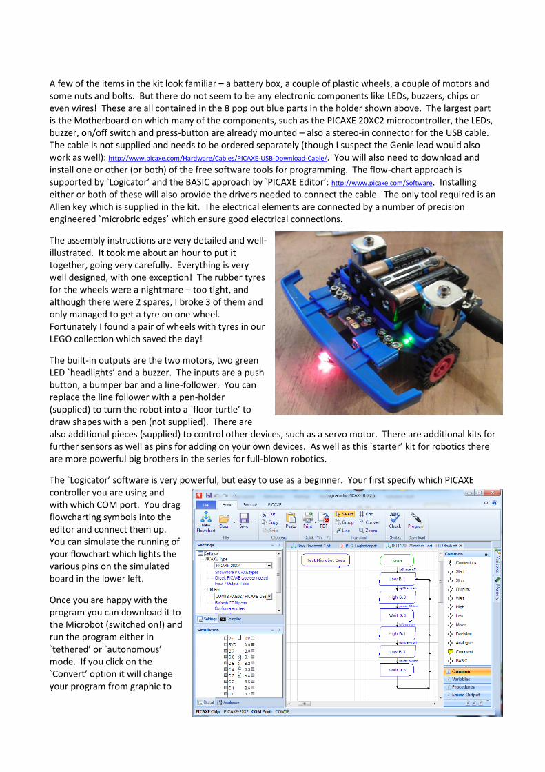
A few of the items in the kit look familiar – a battery box, a couple of plastic wheels, a couple of motors and some nuts and bolts. But there do not seem to be any electronic components like LEDs, buzzers, chips or even wires! These are all contained in the 8 pop out blue parts in the holder shown above. The largest part is the Motherboard on which many of the components, such as the PICAXE 20XC2 microcontroller, the LEDs, buzzer, on/off switch and press-button are already mounted – also a stereo-in connector for the USB cable. The cable is not supplied and needs to be ordered separately (though I suspect the Genie lead would also work as well): http://www.picaxe.com/Hardware/Cables/PICAXE-USB-Download-Cable/. You will also need to download and install one or other (or both) of the free software tools for programming. The flow-chart approach is supported by `Logicator’ and the BASIC approach by `PICAXE Editor’: http://www.picaxe.com/Software. Installing either or both of these will also provide the drivers needed to connect the cable. The only tool required is an Allen key which is supplied in the kit. The electrical elements are connected by a number of precision engineered `microbric edges’ which ensure good electrical connections.
The assembly instructions are very detailed and well-illustrated. It took me about an hour to put it together, going very carefully. Everything is very well designed, with one exception! The rubber tyres for the wheels were a nightmare – too tight, and although there were 2 spares, I broke 3 of them and only managed to get a tyre on one wheel. Fortunately I found a pair of wheels with tyres in our LEGO collection which saved the day!
The built-in outputs are the two motors, two green LED `headlights’ and a buzzer. The inputs are a push button, a bumper bar and a line-follower. You can replace the line follower with a pen-holder (supplied) to turn the robot into a `floor turtle’ to draw shapes with a pen (not supplied). There are also additional pieces (supplied) to control other devices, such as a servo motor. There are additional kits for further sensors as well as pins for adding on your own devices. As well as this `starter’ kit for robotics there are more powerful big brothers in the series for full-blown robotics.
The `Logicator’ software is very powerful, but easy to use as a beginner. Your first specify which PICAXE controller you are using and with which COM port. You drag flowcharting symbols into the editor and connect them up. You can simulate the running of your flowchart which lights the various pins on the simulated board in the lower left.
Once you are happy with the program you can download it to the Microbot (switched on!) and run the program either in `tethered’ or `autonomous’ mode. If you click on the `Convert’ option it will change your program from graphic to
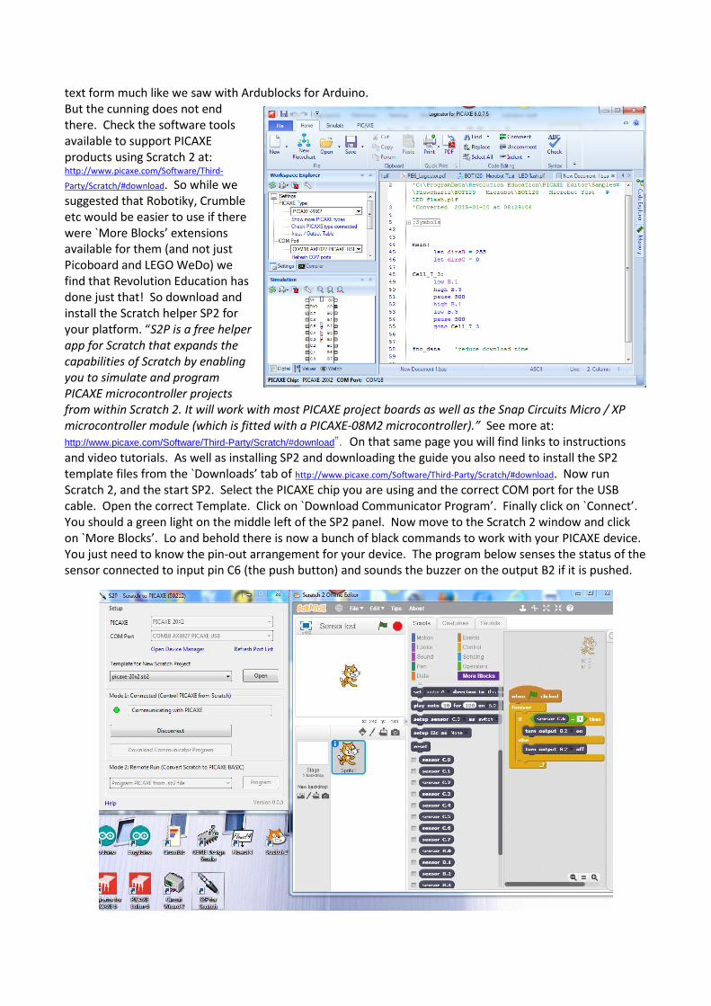
text form much like we saw with Ardublocks for Arduino. But the cunning does not end there. Check the software tools available to support PICAXE products using Scratch 2 at: http://www.picaxe.com/Software/Third-
Party/Scratch/#download. So while we suggested that Robotiky, Crumble etc would be easier to use if there were `More Blocks’ extensions available for them (and not just Picoboard and LEGO WeDo) we find that Revolution Education has done just that! So download and install the Scratch helper SP2 for your platform. “S2P is a free helper app for Scratch that expands the capabilities of Scratch by enabling you to simulate and program PICAXE microcontroller projects from within Scratch 2. It will work with most PICAXE project boards as well as the Snap Circuits Micro / XP microcontroller module (which is fitted with a PICAXE-08M2 microcontroller).” See more at: http://www.picaxe.com/Software/Third-Party/Scratch/#download”. On that same page you will find links to instructions and video tutorials. As well as installing SP2 and downloading the guide you also need to install the SP2 template files from the `Downloads’ tab of http://www.picaxe.com/Software/Third-Party/Scratch/#download. Now run Scratch 2, and the start SP2. Select the PICAXE chip you are using and the correct COM port for the USB cable. Open the correct Template. Click on `Download Communicator Program’. Finally click on `Connect’. You should a green light on the middle left of the SP2 panel. Now move to the Scratch 2 window and click on `More Blocks’. Lo and behold there is now a bunch of black commands to work with your PICAXE device. You just need to know the pin-out arrangement for your device. The program below senses the status of the sensor connected to input pin C6 (the push button) and sounds the buzzer on the output B2 if it is pushed.

There is an excelleny starter kit of sensors and outputs for £40 + VAT + p/p. This is also compatible with the BOT 120 kit: http://www.picaxe.com/Hardware/Teaching-Systems/Create-Starter-Pack/. You will need to a little light soldering.
So now we have the met probably the most sophisticated system so far, with cheap hardware, free software, extensive support plus the ability to run as hardware supported by Scratch 2 `More Blocks’ commands. Next we look at the simplest of all the systems so far designed to add physical computing application to the commonly used Python programming language (named after `Monty Python’!).
11. Micropython: For £30 I bought the minute Micro Python pyboard v1.0: https://micropython.org/ . This is a product of George Robotics in Cambridge designed by Damien George, a Cambridge don who raised the capital for the project through Kickstarter: https://www.kickstarter.com/projects/214379695/micro-python-python-for-microcontrollers. So this is an ideal tool to use to get into programming in Python for physical applications. Attach the board to your computer with a USB to micro USB mobile phone cable. The board appears as an external drive called PYBFLASH with a small memory, which can be extended by the insertion of a micro-SD memory card. You write your program in Python 3 in a text editor and save it to the drive as “main.py”. Then unplug the board, plug it back in, press the reset button and away you go! A large amount of reference material is at: http://docs.micropython.org/en/latest/quickref.html. Tutorials are at: http://docs.micropython.org/en/latest/tutorial/index.html.
The final system in this chapter is on one of the simplest systems of all.
12. Mindsets IQ4 This is a very simple and very cheap microcontroller of the Crumble variety but which does not require a computer to program it! It costs £7.14 inc VAT from Mindsets Online. Information on the board is at: http://www.mindsetsonline.co.uk/Downloads/IQ4.pdf and tutorials on its use are at: http://www.mindsetsonline.co.uk/Downloads/iq4_systems.pdf. All you need is a battery box and 3 AA batteries.

The tutorials are extremely clear as shown here. There are 6 on-board buttons. One controls the input you connect on one side of the board – such as a switch or sensor. Two control the outputs you connect on the other side of the board (or just the on-board LEDs). One button is used to select the board’s mode – RUN or PROGRAM. The other is the SAVE button to enter each line of the program. In the example here we just blink the on-board LED for Output 1. There is no visible code for the
program so it is suggested you write your own in the form of a table such as:
Again, the tutorial give a welter of suggestion for projects you can build by connecting the IQ4 to different components.
13. Résumé When I set out on this voyage I had no idea what a rich field I was stumbling across. In this episode we have just met UK designed educational products – illustrating a wide range of programming techniques from button pushes, through flowcharts to Scratch, Basic and Python. In what I hope will be the final part I will concentrate on resources designed to be used with the Raspberry Pi for physical computing, as well as taking a look at LEGO’s Mindstorms systems.