learning text part 9 specifications - · pdf filespecifications macintosh...
TRANSCRIPT

Specifications
Macintosh HD:Users:jennycarr:Desktop:extras:LT - Specifications #47E93A.doc Page 1 of 2124thApril 2007
Learning Text
Part 9
Specifications
Specifications
Macintosh HD:Users:jennycarr:Desktop:extras:LT - Specifications #47E93A.doc Page 2 of 2124thApril 2007
Contents Page
Introduction 3
Historical 3
The functions of masonry mortar 3
Design requirements 4
Strength and stability (structural requirements) 4 Weather resistance 5
Durability 5Fire resistance 6Thermal insulation 7Sound insulation 7
Methods of specifying masonry mortar 7
General 7Prescribed masonry mortars 7
Designed masonry mortars 8 Specification drafting 9
The functions of rendering mortar 10
Design requirements 10
Background 10Durability 12
Methods of specifying rendering mortar 13
Prescribed rendering mortars 13
Designed rendering mortars 14
Glossary of terms 16
Bibliography 19
Self-Assessment Questions 20
Answers to Self-Assessment Questions 21
Specifications
Macintosh HD:Users:jennycarr:Desktop:extras:LT - Specifications #47E93A.doc Page 3 of 2124thApril 2007
Introduction
This learning text considers the subject of the specification of masonry and renderingmortars. The text discusses the historical evolution of specifications and currentrequirements. Information is given on the parameters that need to be considered in thepreparation of a specification. A glossary of terminology and bibliography are included. Thefinal section of this learning text is self-assessment questions and answers.
Historical
The earliest documented use of mortar is around 4000 B.C. It is mentioned several times inthe old testament of the bible. However, it was the Romans who really developed itsstructural use. Vitrivius a military engineer who worked under Julius Caesar wrote aspecification for sand, lime and bricks to be used in masonry. He stated, “In buildings ofrubble work it is of the first importance that the sand be fit for mixing with the lime, andunalloyed with earth”. He further stated “though pit sand is excellent for mortar, it is unfitfor plastering for being such a rich quality, when added to the lime and straw, its greatstrength does not suffer it to dry without cracks”.
Historically, mortars have been specified on a volume basis, probably because they havealmost always been mixed on site by the shovelfull, for example one shovelful of cement orlime to perhaps three or six shovelfuls of sand (fine aggregate). This would be written inspecification terms as a 1 : 3 or a 1 : 6.
The term specification may be defined in relation to construction as, a document containing adetailed description of the particulars of some projected work in building, engineering orsimilar, giving the dimensions, materials, quantities etc, of the work together with directionsto be followed by the builder or constructor.
The functions of masonry mortar
Prior to specifying masonry mortar it is very important to understand how the constituentmaterials determine the fresh and hardened properties of the mortar and how the mortarcontributes to the successful performance of the masonry. Masonry mortar has a number offunctions:
• To act as an adhesive (to glue) the masonry units together,• To glue joint reinforcement and connectors to the masonry units,• To act as a spacer between masonry units,• To compensate for irregularities between masonry units,• To seal any gaps to minimise rain or wind penetration,• To have sufficient strength to suit the application,• To be durable in the particular environment.
In addition the colour of hardened masonry mortar contributes to the overall aestheticappearance of the finished construction, therefore the colour of the mortar and the method offinishing (workmanship) need to be considered when drafting the specification.
The learning text entitled “Properties of Masonry Mortar” (Learning Text 6) discusses thedesirable qualities for a masonry mortar in greater depth.
Design requirements

Specifications
Macintosh HD:Users:jennycarr:Desktop:extras:LT - Specifications #47E93A.doc Page 4 of 2124thApril 2007
Drafting a specification is a complex matter, many parameters have to be taken into account,this section of the learning text discusses a number of the factors that have to be considered inthe compilation of the specification.
The design of masonry construction is covered by BS 5628-3; clause 5 entitled “Design” liststhe factors that should be taken into account. The statement is made that “Considerationshould be given to the interaction of the whole structure, of which the masonry forms a part”.This statement highlights the importance of not considering masonry and mortar in isolationfrom the other building components. Parts 1 and 2 of BS 5628 provide further guidance forthe designer of the masonry and mortar, on the parameters to be considered in the preparationof the specification for particular construction applications and environments.
The parameters to be considered in drafting a specification for masonry include:
• Strength and stability,• Weather resistance,• Durability,• Fire resistance,• Thermal insulation,• Sound insulation.
Each of these parameters is now briefly discussed.
Strength and stability (structural requirements)
A large percentage of masonry construction is in the form of walls for houses or walls andpiers for other buildings. These together with the roof form the environmental envelope of thebuilding, the walls very frequently become the basic supporting elements.
The designer of a masonry construction is required to consider the forces acting on theelement being designed, these include:
• The thickness in relation to the height and width of the construction,• The weight of the element,• The presence of piers,• The application of concentrated loads to walls,• The application of lateral loads to walls (e.g. wind),• Movement,• The interaction with other construction elements.
Consideration of these factors enables the designer to determine the most suitable form ofconstruction and the range of materials that may be used.
Specifications
Macintosh HD:Users:jennycarr:Desktop:extras:LT - Specifications #47E93A.doc Page 5 of 2124thApril 2007
Weather resistance
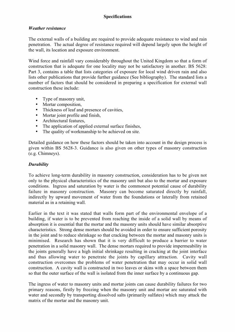
The external walls of a building are required to provide adequate resistance to wind and rainpenetration. The actual degree of resistance required will depend largely upon the height ofthe wall, its location and exposure environment.
Wind force and rainfall vary considerably throughout the United Kingdom so that a form ofconstruction that is adequate for one locality may not be satisfactory in another. BS 5628:Part 3, contains a table that lists categories of exposure for local wind driven rain and alsolists other publications that provide further guidance (See bibliography). The standard lists anumber of factors that should be considered in preparing a specification for external wallconstruction these include:
• Type of masonry unit,• Mortar composition,• Thickness of leaf and presence of cavities,• Mortar joint profile and finish,• Architectural features,• The application of applied external surface finishes,• The quality of workmanship to be achieved on site.
Detailed guidance on how these factors should be taken into account in the design process isgiven within BS 5628-3. Guidance is also given on other types of masonry construction(e.g. Chimneys).
Durability
To achieve long-term durability in masonry construction, consideration has to be given notonly to the physical characteristics of the masonry unit but also to the mortar and exposureconditions. Ingress and saturation by water is the commonest potential cause of durabilityfailure in masonry construction. Masonry can become saturated directly by rainfall,indirectly by upward movement of water from the foundations or laterally from retainedmaterial as in a retaining wall.
Earlier in the text it was stated that walls form part of the environmental envelope of abuilding, if water is to be prevented from reaching the inside of a solid wall by means ofabsorption it is essential that the mortar and the masonry units should have similar absorptivecharacteristics. Strong dense mortars should be avoided in order to ensure sufficient porosityin the joint and to reduce shrinkage so that cracking between the mortar and masonry units isminimised. Research has shown that it is very difficult to produce a barrier to waterpenetration in a solid masonry wall. The dense mortars required to provide impermeability inthe joints generally have a high initial shrinkage resulting in cracking at the joint interfaceand thus allowing water to penetrate the joints by capillary attraction. Cavity wallconstruction overcomes the problems of water penetration that may occur in solid wallconstruction. A cavity wall is constructed in two leaves or skins with a space between themso that the outer surface of the wall is isolated from the inner surface by a continuous gap.
The ingress of water to masonry units and mortar joints can cause durability failures for twoprimary reasons, firstly by freezing when the masonry unit and mortar are saturated withwater and secondly by transporting dissolved salts (primarily sulfates) which may attack thematrix of the mortar and the masonry unit.

Specifications
Macintosh HD:Users:jennycarr:Desktop:extras:LT - Specifications #47E93A.doc Page 6 of 2124thApril 2007
The architect or designer may minimise the likelihood of masonry units and mortar becomingsaturated with water by incorporating features in the design such as roof overhangs orcopings.
Most parts of the United Kingdom experience night frosts during the winter months. It isimportant to remember that low temperatures alone do not lead to the deterioration ofmasonry units and mortar. Where a combination of water saturation and low temperatures ofthe masonry units or mortar occurs, the water may be converted into ice. This change of stateresults in an increase in volume of the water of approximately 9%. The result of thetransformation of the water is that stresses may be set up which the masonry unit or mortarcannot withstand leading to spalling of the masonry unit and crumbling of the mortar. Theseverity of freeze thaw damage increases with more frequent freeze thaw cycles rather than aprolonged period of freezing.
BS 5628-3 contains an extensive table entitled “Durability of masonry in finishedconstruction”; this lists various exposure conditions, types of masonry units and appropriatemortar designations. The specification of a mortar containing an air entraining admixtureimproves the resistance of the mortar to freeze thaw deterioration.
Certain types of masonry construction are more likely to become water saturated and remainso for considerable periods of time. (e.g. Chimney stacks, retaining walls, parapets andconstruction below damp proof courses). The designer should specify appropriate materialsfor these environments.
Sulfate attack is principally caused by the reaction between sulfates in solution and thetricalcium aluminate in cement (C3A), (See Learning Text 2: Cementitious materials). Therisk of sulfate attack can be reduced by using a cement with a low C3A content or a Portlandcement (CEM I), with which pulverized fly ash or ground granulated blastfurnace slag hasbeen combined.
Some types of bricks can provide a source of sulfates, it possible to specify bricks with a lowacid soluble content, calcium sulfate bricks and concrete masonry units do not contain solublesulfates. Where masonry construction is to take place below ground level, or masonryretaining walls are to be constructed it is essential that chemical analysis be undertaken todetermine the concentration and type of sulfates present. BRE Special Digest 1 providesguidance on “Concrete in aggressive ground”, much of the information is applicable tomortar. The digest contains information on site investigations, the classification ofaggressive chemicals in the soil and the mobility of groundwater.
Fire resistance
BS 5628 provides guidance on the notional fire resistance of walls, tables list the thickness ofmasonry required for different time periods of fire resistance based on the composition of themasonry unit. (See glossary for further information on fire resistance.)
Specifications
Macintosh HD:Users:jennycarr:Desktop:extras:LT - Specifications #47E93A.doc Page 7 of 2124thApril 2007
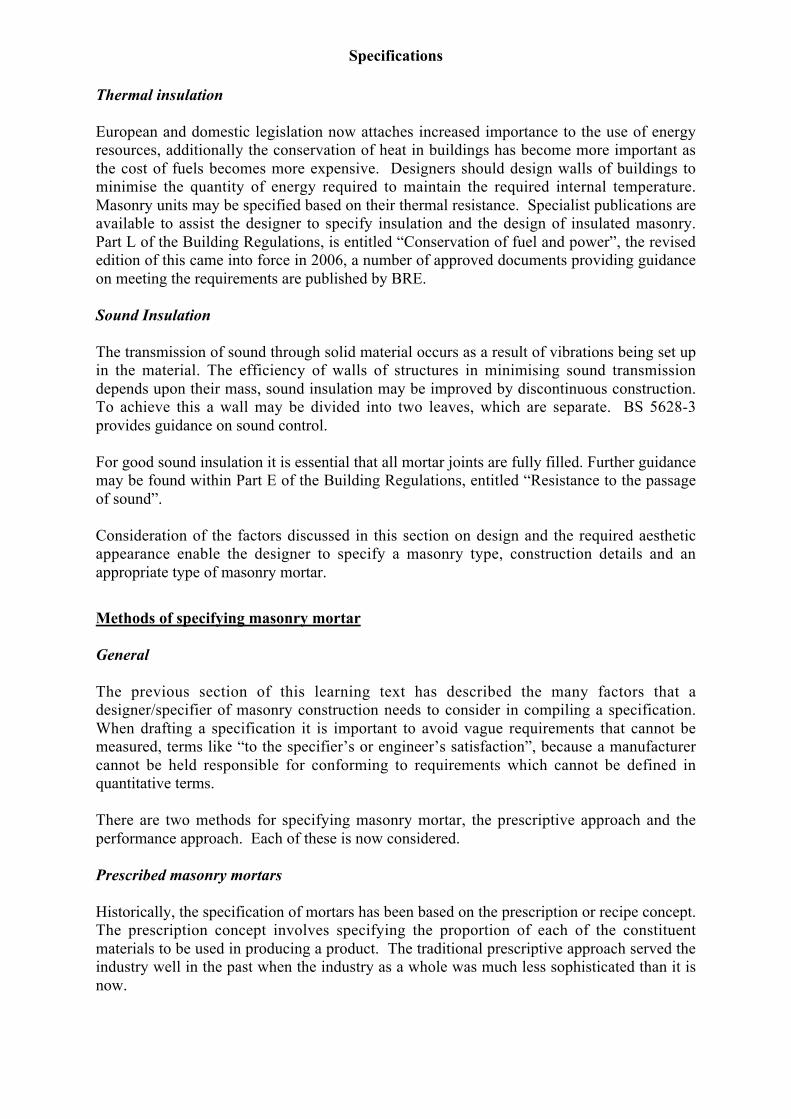
Thermal insulation
European and domestic legislation now attaches increased importance to the use of energyresources, additionally the conservation of heat in buildings has become more important asthe cost of fuels becomes more expensive. Designers should design walls of buildings tominimise the quantity of energy required to maintain the required internal temperature.Masonry units may be specified based on their thermal resistance. Specialist publications areavailable to assist the designer to specify insulation and the design of insulated masonry.Part L of the Building Regulations, is entitled “Conservation of fuel and power”, the revisededition of this came into force in 2006, a number of approved documents providing guidanceon meeting the requirements are published by BRE.
Sound Insulation
The transmission of sound through solid material occurs as a result of vibrations being set upin the material. The efficiency of walls of structures in minimising sound transmissiondepends upon their mass, sound insulation may be improved by discontinuous construction.To achieve this a wall may be divided into two leaves, which are separate. BS 5628-3provides guidance on sound control.
For good sound insulation it is essential that all mortar joints are fully filled. Further guidancemay be found within Part E of the Building Regulations, entitled “Resistance to the passageof sound”.
Consideration of the factors discussed in this section on design and the required aestheticappearance enable the designer to specify a masonry type, construction details and anappropriate type of masonry mortar.
Methods of specifying masonry mortar
General
The previous section of this learning text has described the many factors that adesigner/specifier of masonry construction needs to consider in compiling a specification.When drafting a specification it is important to avoid vague requirements that cannot bemeasured, terms like “to the specifier’s or engineer’s satisfaction”, because a manufacturercannot be held responsible for conforming to requirements which cannot be defined inquantitative terms.
There are two methods for specifying masonry mortar, the prescriptive approach and theperformance approach. Each of these is now considered.
Prescribed masonry mortars
Historically, the specification of mortars has been based on the prescription or recipe concept.The prescription concept involves specifying the proportion of each of the constituentmaterials to be used in producing a product. The traditional prescriptive approach served theindustry well in the past when the industry as a whole was much less sophisticated than it isnow.
Specifications
Macintosh HD:Users:jennycarr:Desktop:extras:LT - Specifications #47E93A.doc Page 8 of 2124thApril 2007
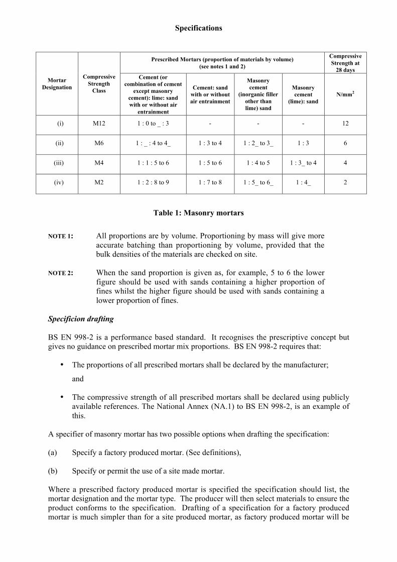
Prescriptions or recipes have been developed to encompass a range of materials properties,including those at the lower end of the range permitted by their standards. This has resulted inthe lowest common denominator being set as the material requirement. A very conservativeand often wasteful approach. This means that in practice the mix proportions have been setto allow the lowest quality fine aggregate (sand) permitted by the standard to be used, and toproduce a mortar with satisfactory properties. Clearly, for much better quality fineaggregates, the mix proportions which were set to accommodate the lower quality material,will produce a product that greatly exceeds the actual requirements. See Note 2 of Table 1.
This approach tends to inhibit the most efficient use of the constituent materials available toproduce a mortar
The prescriptive system of specifying masonry mortar adopted by British Standards manyyears ago is based on mortar designations. Mortars of different constituent materialcompositions which had approximately equivalent compressive strengths were given thesame numeric designations, the nomenclature adopted used lower case Roman numerals.Conformity with a prescription specification and the associated strength class does notprovide the specifier with a guarantee of the durability of the mortar. However, somespecifiers prefer to prescribe the mortar constituents based on their own personal experienceof the use of particular materials.
BS 5628–3 includes a table (an extract from this is reproduced as Table 1) showing thetraditional mortar designations. The compressive strength class should be regarded as thecharacteristic compressive strength that may be expected from the use of these materialswhen tested at twenty-eight days. It should be noted that compressive strength is determinedon prism specimens not cube specimens and a conversion factor needs to be applied wherecube specimens are used. The compressive strength classes listed in Table 1 do notcorrespond to the strength classes listed in BS 998-2, the values listed in Table 1 are based onlimited laboratory data for each of the designations. (These values have been included withinthe informative National annex to BS EN 998-2 (NA.1), however these are beingreconsidered to reflect experience gained from actual production since the introduction of thestandard.)
Designed masonry mortars
A specifier of a factory produced designed masonry mortar should specify one of the mortarclasses listed in Table 1 of BS EN 998-2 together with requirements for workable life.Where relevant chloride content and/or air content should also be specified. For somespecialised applications the specifier may need to specify additional requirements (e.g.density or water vapour permeability). The presence of chlorides can cause corrosion of anyembedded metal, the incorporation of an air entraining admixture increases the resistance ofthe mortar to freeze thaw attack. The producer of the mortar will use his expert knowledgeand database to select an appropriate combination of constituent materials to produce amasonry mortar with the desired characteristics. Conformity of the mortar with thespecification will be evaluated in accordance with Clause 8 of BS EN 998-2.
Where it is desired to produce a designed mortar on site, the contractor will have to undertaketrials to establish suitable combinations of materials to satisfy the requirements for theparticular applications. The specifier should include in the specification requirements,routine quality control, sampling and the evaluation of conformity of the mortar.
Specifications
Macintosh HD:Users:jennycarr:Desktop:extras:LT - Specifications #47E93A.doc Page 9 of 2124thApril 2007
Prescribed Mortars (proportion of materials by volume)(see notes 1 and 2)
CompressiveStrength at
28 days
MortarDesignation
CompressiveStrength
Class
Cement (orcombination of cement
except masonrycement): lime: sandwith or without air
entrainment
Cement: sandwith or withoutair entrainment
Masonrycement
(inorganic fillerother thanlime) sand
Masonrycement
(lime): sandN/mm2
(i) M12 1 : 0 to _ : 3 - - - 12
(ii) M6 1 : _ : 4 to 4_ 1 : 3 to 4 1 : 2_ to 3_ 1 : 3 6
(iii) M4 1 : 1 : 5 to 6 1 : 5 to 6 1 : 4 to 5 1 : 3_ to 4 4
(iv) M2 1 : 2 : 8 to 9 1 : 7 to 8 1 : 5_ to 6_ 1 : 4_ 2
Table 1: Masonry mortars
NOTE 1: All proportions are by volume. Proportioning by mass will give moreaccurate batching than proportioning by volume, provided that thebulk densities of the materials are checked on site.
NOTE 2: When the sand proportion is given as, for example, 5 to 6 the lowerfigure should be used with sands containing a higher proportion offines whilst the higher figure should be used with sands containing alower proportion of fines.
Specificion drafting
BS EN 998-2 is a performance based standard. It recognises the prescriptive concept butgives no guidance on prescribed mortar mix proportions. BS EN 998-2 requires that:
• The proportions of all prescribed mortars shall be declared by the manufacturer;
and
• The compressive strength of all prescribed mortars shall be declared using publiclyavailable references. The National Annex (NA.1) to BS EN 998-2, is an example ofthis.
A specifier of masonry mortar has two possible options when drafting the specification:
(a) Specify a factory produced mortar. (See definitions),
(b) Specify or permit the use of a site made mortar.
Where a prescribed factory produced mortar is specified the specification should list, themortar designation and the mortar type. The producer will then select materials to ensure theproduct conforms to the specification. Drafting of a specification for a factory producedmortar is much simpler than for a site produced mortar, as factory produced mortar will be
Specifications
Macintosh HD:Users:jennycarr:Desktop:extras:LT - Specifications #47E93A.doc Page 10 of 2124thApril 2007
manufactured under a production control system. This requires that procedures are in placefor the selection of constituent materials, their storage, batching and mixing. The standardBS EN 998-2 also prescribes conformity evaluation requirements for factory producedmortar.
The specification of site produced mortar requires the specifier to list all the relevant criteriathat is included within a factory production control system, clause 8 of PD 6678 providesguidance on the requirements to be included within a specification for site produced masonrymortar. Site investigations have shown that the principal reasons for inconsistencies in siteproduced mortar are the methods used to batch the constituent materials, the order of placingthese in the mixer and the duration of mixing. Therefore the specifier should prescribe howthese activities are to be undertaken during the production of site produced mortar.
A general principle of specification drafting mentioned at the start of this section is thatcharacteristics which cannot be measured should not be specified, as the assessment ofconformity would be subjective. An exception is the specification of colour andworkmanship, where this is to be specified reference panels should be constructed. It isimportant that the standard used to construct these represents that which can be achieved withnormal construction methods.
The functions of rendering mortar
The learning text on the Properties of rendering mortar (Learning text 12) states that theprincipal reasons for using a rendering mortar are to:
• Provide a barrier to prevent rain from penetrating into the background masonry,• Enhance the appearance of a plain masonry structure.
A rendering mortar is required to adhere to the background in the fresh state and maintain thisadhesion for the life of the building. The render should be resistant to frost and sulfate attack.
Design Requirements
In designing a rendering system consideration should be given to the desired appearance(Learning Text 13 discusses a number of finishes), the type of background and the functionalrequirements.
A rendering system normally consists of a minimum of two coats, however it should be notedthat specially formulated one coat systems have been developed.
Background
The background to which the render is to be applied must be assessed. If physical adhesion ofthe applied render is insufficient then an effective mechanical key is essential. Where metallathing is used adhesion is solely based on mechanical key. The background is required toadequately support and restrain the rendering, it is recommended that the background shouldnot be weaker and preferably stronger than the rendering that is to be applied. This maynecessitate the application of stronger renders on to an expanded metal lathing fixed to timberbattens which have been treated with a preservative.
The adhesion of a rendering is largely determined by the suction of the backgroundparticularly when there is not an adequate key. High and low rates of suction can impair the
Specifications
Macintosh HD:Users:jennycarr:Desktop:extras:LT - Specifications #47E93A.doc Page 11 of 2124thApril 2007
development of a satisfactory bond, suction rates can be affected significantly by the moisturecontent of the background at any particular time.
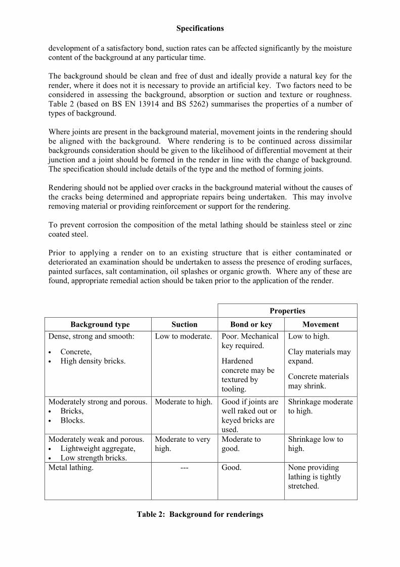
The background should be clean and free of dust and ideally provide a natural key for therender, where it does not it is necessary to provide an artificial key. Two factors need to beconsidered in assessing the background, absorption or suction and texture or roughness.Table 2 (based on BS EN 13914 and BS 5262) summarises the properties of a number oftypes of background.
Where joints are present in the background material, movement joints in the rendering shouldbe aligned with the background. Where rendering is to be continued across dissimilarbackgrounds consideration should be given to the likelihood of differential movement at theirjunction and a joint should be formed in the render in line with the change of background.The specification should include details of the type and the method of forming joints.
Rendering should not be applied over cracks in the background material without the causes ofthe cracks being determined and appropriate repairs being undertaken. This may involveremoving material or providing reinforcement or support for the rendering.
To prevent corrosion the composition of the metal lathing should be stainless steel or zinccoated steel.
Prior to applying a render on to an existing structure that is either contaminated ordeteriorated an examination should be undertaken to assess the presence of eroding surfaces,painted surfaces, salt contamination, oil splashes or organic growth. Where any of these arefound, appropriate remedial action should be taken prior to the application of the render.
Properties
Background type Suction Bond or key MovementDense, strong and smooth:
• Concrete,• High density bricks.
Low to moderate. Poor. Mechanicalkey required.
Hardenedconcrete may betextured bytooling.
Low to high.
Clay materials mayexpand.
Concrete materialsmay shrink.
Moderately strong and porous.• Bricks,• Blocks.
Moderate to high. Good if joints arewell raked out orkeyed bricks areused.
Shrinkage moderateto high.
Moderately weak and porous.• Lightweight aggregate,• Low strength bricks.
Moderate to veryhigh.
Moderate togood.
Shrinkage low tohigh.
Metal lathing. --- Good. None providinglathing is tightlystretched.
Table 2: Background for renderings

Specifications
Macintosh HD:Users:jennycarr:Desktop:extras:LT - Specifications #47E93A.doc Page 12 of 2124thApril 2007
Durability
Rendering will be affected by exposure to the combined actions of frost, wind sun and rain.The effects of these environmental factors will depend to some extent to the degree ofexposure. Learning text 13 discusses the exposure classification system. The type ofbackground, the composition of the rendering and workmanship will also influencedurability. The specification of a durable rendering system requires the specifier to considera number of parameters. These are now briefly discussed.
Rain penetration
One of the prime purposes of applying a rendering system is to minimise or eliminate rainpenetration into the background construction, attention should therefore be given tominimising cracking. Where a prescribed mortar is to be used the specifier will have to relyon his knowledge of the local constituent materials to specify a suitable mortar for theexposure conditions. The specification of a designed mortar simplifies the specificationprocess, this form of specification does not require the specifier to have local knowledge ofthe constituent materials. For severe conditions of exposure where the rendering is subject toheavy rainfall a rendering mortar with a capillary water absorption of Class W2 should bespecified. In sheltered and moderate conditions a render with a capillary water absorption ofClass WO or W1 should provide a satisfactory barrier to the ingress of rain.
Where masonry is in contact with the ground special waterproofing mortars may be required,on backgrounds that are susceptible to dampness the specification of a renovation mortar maybe appropriate.
The National Annex to BS EN 13191-1 contains guidance on exposure categories for winddriven rain and measures to increase resistance to rain penetration.
Soluble salts
Some backgrounds may contain soluble salts, these may arise from the masonry or fromrising damp. In new construction attention to detailing can minimise the occurrence of theproblem in older construction consideration should be given to the use of a renovationmortar.
Atmospheric pollution
Atmospheric pollution may result in localised surface discolouration, due to airborne dirt anddust. In selecting a rendering system the specifier should take into account the exteriorfeatures of the building.
Frost attack
Potential problems associated with frost attack can be minimised by the specification of arender incorporating an air entraining admixture.
Corrosion of metals
To minimise the risk of corrosion of metal lathing and fixings, consideration should be givento specifying stainless steel or zinc coated steel products. In extreme exposure conditions(splash zones) stainless steel products should be specified.
Specifications
Macintosh HD:Users:jennycarr:Desktop:extras:LT - Specifications #47E93A.doc Page 13 of 2124thApril 2007
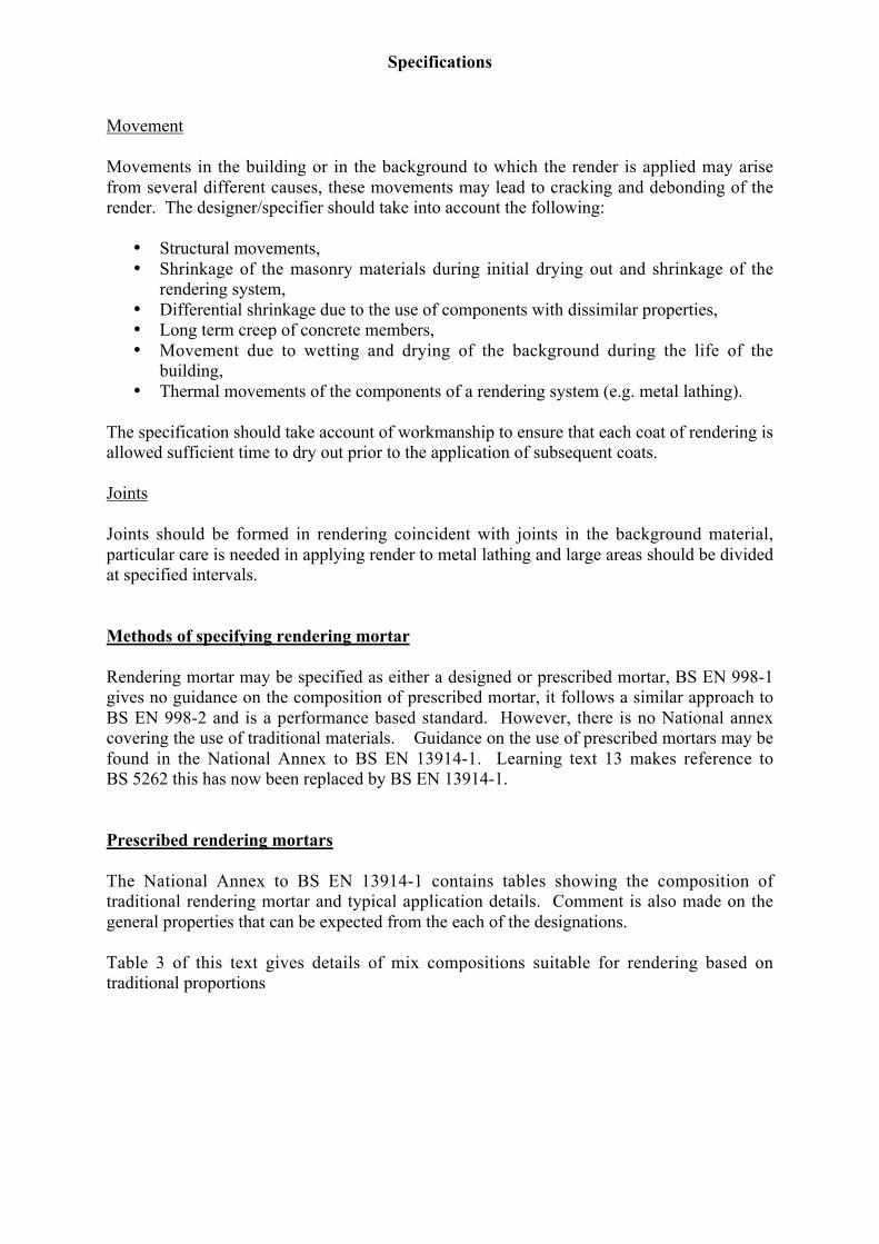
Movement
Movements in the building or in the background to which the render is applied may arisefrom several different causes, these movements may lead to cracking and debonding of therender. The designer/specifier should take into account the following:
• Structural movements,• Shrinkage of the masonry materials during initial drying out and shrinkage of the
rendering system,• Differential shrinkage due to the use of components with dissimilar properties,• Long term creep of concrete members,• Movement due to wetting and drying of the background during the life of the
building,• Thermal movements of the components of a rendering system (e.g. metal lathing).
The specification should take account of workmanship to ensure that each coat of rendering isallowed sufficient time to dry out prior to the application of subsequent coats.
Joints
Joints should be formed in rendering coincident with joints in the background material,particular care is needed in applying render to metal lathing and large areas should be dividedat specified intervals.
Methods of specifying rendering mortar
Rendering mortar may be specified as either a designed or prescribed mortar, BS EN 998-1gives no guidance on the composition of prescribed mortar, it follows a similar approach toBS EN 998-2 and is a performance based standard. However, there is no National annexcovering the use of traditional materials. Guidance on the use of prescribed mortars may befound in the National Annex to BS EN 13914-1. Learning text 13 makes reference toBS 5262 this has now been replaced by BS EN 13914-1.
Prescribed rendering mortars
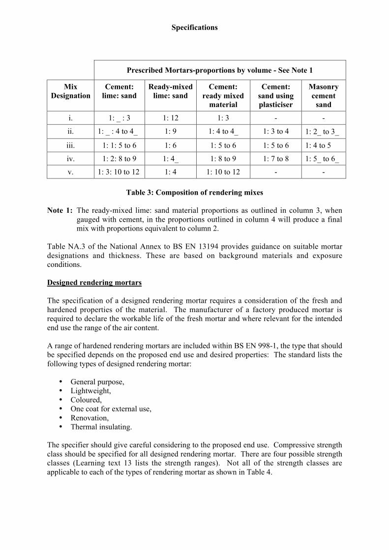
The National Annex to BS EN 13914-1 contains tables showing the composition oftraditional rendering mortar and typical application details. Comment is also made on thegeneral properties that can be expected from the each of the designations.
Table 3 of this text gives details of mix compositions suitable for rendering based ontraditional proportions
Specifications
Macintosh HD:Users:jennycarr:Desktop:extras:LT - Specifications #47E93A.doc Page 14 of 2124thApril 2007
Prescribed Mortars-proportions by volume - See Note 1
MixDesignation
Cement:lime: sand
Ready-mixedlime: sand
Cement:ready mixed
material
Cement:sand usingplasticiser
Masonrycement
sand
i. 1: _ : 3 1: 12 1: 3 - -
ii. 1: _ : 4 to 4_ 1: 9 1: 4 to 4_ 1: 3 to 4 1: 2_ to 3_
iii. 1: 1: 5 to 6 1: 6 1: 5 to 6 1: 5 to 6 1: 4 to 5
iv. 1: 2: 8 to 9 1: 4_ 1: 8 to 9 1: 7 to 8 1: 5_ to 6_
v. 1: 3: 10 to 12 1: 4 1: 10 to 12 - -
Table 3: Composition of rendering mixes
Note 1: The ready-mixed lime: sand material proportions as outlined in column 3, whengauged with cement, in the proportions outlined in column 4 will produce a finalmix with proportions equivalent to column 2.
Table NA.3 of the National Annex to BS EN 13194 provides guidance on suitable mortardesignations and thickness. These are based on background materials and exposureconditions.
Designed rendering mortars
The specification of a designed rendering mortar requires a consideration of the fresh andhardened properties of the material. The manufacturer of a factory produced mortar isrequired to declare the workable life of the fresh mortar and where relevant for the intendedend use the range of the air content.
A range of hardened rendering mortars are included within BS EN 998-1, the type that shouldbe specified depends on the proposed end use and desired properties: The standard lists thefollowing types of designed rendering mortar:
• General purpose,• Lightweight,• Coloured,• One coat for external use,• Renovation,• Thermal insulating.
The specifier should give careful considering to the proposed end use. Compressive strengthclass should be specified for all designed rendering mortar. There are four possible strengthclasses (Learning text 13 lists the strength ranges). Not all of the strength classes areapplicable to each of the types of rendering mortar as shown in Table 4.

Specifications
Macintosh HD:Users:jennycarr:Desktop:extras:LT - Specifications #47E93A.doc Page 15 of 2124thApril 2007
Type of designedrendering mortar
Compressive strengthclasses
(determined inaccordance withBS EN 1015-11)
Capillary waterabsorption
(determined inaccordance withBS EN 1015-18)
Water vapourpermeabilitycoefficient (_)determined in
accordance withBS EN 1015-19)
General purpose CS I to CS IV W O to W 2 < Declared value
Lightweight CS I to CS III W O to W 2 < Declared value
Coloured CS I to IV W O to W 2 < Declared value
One coat CS I to IV W 1 to W 2 < Declared value
Renovation CS II > 0,3 kg/m2 after24 hours < 15
Thermal insulating CS I to CS II W 1 < 15
Table 4: Hardened properties of designed rendering mortar
For each of the types of rendering mortar listed in Table 3 the manufacturer is required todeclare the dry bulk density when tested in accordance with BS EN 1015-10. Themanufacturer is also required to declare an adhesion value and fracture pattern for all typesexcept one coat rendering systems (determined in accordance with BS EN 1015-12). For onecoat systems the adhesion should be determined after the test specimens have undergone aseries of weathering cycles (BS EN 1015-21) and the water permeability on relevantsubstrates should also determined.
Where the render is to be used in external elements the capillary water absorption should bespecified in accordance with the ranges shown in Table 4, additionally for renovation rendersthe water penetration should be determined after the completion of the capillary waterabsorption test and is required to be equal to or less than 5mm. The water vapourpermeability coefficient should be determined and declared by the manufacturer, forrenovation and thermal insulating mortars specific maximum values are prescribed. Thermalconductivity may be calculated from tabulated values specific requirements are prescribed forthermal insulating rendering mortars.
Specifications
Macintosh HD:Users:jennycarr:Desktop:extras:LT - Specifications #47E93A.doc Page 16 of 2124thApril 2007
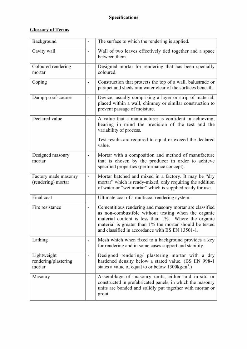
Glossary of Terms
Background - The surface to which the rendering is applied.
Cavity wall - Wall of two leaves effectively tied together and a spacebetween them.
Coloured renderingmortar
- Designed mortar for rendering that has been speciallycoloured.
Coping - Construction that protects the top of a wall, balustrade orparapet and sheds rain water clear of the surfaces beneath.
Damp-proof-course - Device, usually comprising a layer or strip of material,placed within a wall, chimney or similar construction toprevent passage of moisture.
Declared value - A value that a manufacturer is confident in achieving,bearing in mind the precision of the test and thevariability of process.
Test results are required to equal or exceed the declaredvalue.
Designed masonrymortar
- Mortar with a composition and method of manufacturethat is chosen by the producer in order to achievespecified properties (performance concept).
Factory made masonry(rendering) mortar
- Mortar batched and mixed in a factory. It may be “drymortar” which is ready-mixed, only requiring the additionof water or “wet mortar” which is supplied ready for use.
Final coat - Ultimate coat of a multicoat rendering system.
Fire resistance - Cementitious rendering and masonry mortar are classifiedas non-combustible without testing when the organicmaterial content is less than 1%. Where the organicmaterial is greater than 1% the mortar should be testedand classified in accordance with BS EN 13501-1.
Lathing - Mesh which when fixed to a background provides a keyfor rendering and in some cases support and stability.
Lightweightrendering/plasteringmortar
- Designed rendering/ plastering mortar with a dryhardened density below a stated value. (BS EN 998-1states a value of equal to or below 1300kg/m3.)
Masonry - Assemblage of masonry units, either laid in-situ orconstructed in prefabricated panels, in which the masonryunits are bonded and solidly put together with mortar orgrout.
Specifications
Macintosh HD:Users:jennycarr:Desktop:extras:LT - Specifications #47E93A.doc Page 17 of 2124thApril 2007
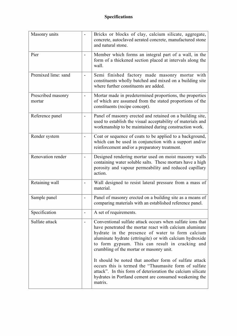
Masonry units - Bricks or blocks of clay, calcium silicate, aggregate,concrete, autoclaved aerated concrete, manufactured stoneand natural stone.
Pier - Member which forms an integral part of a wall, in theform of a thickened section placed at intervals along thewall.
Premixed lime: sand - Semi finished factory made masonry mortar withconstituents wholly batched and mixed on a building sitewhere further constituents are added.
Prescribed masonrymortar
- Mortar made in predetermined proportions, the propertiesof which are assumed from the stated proportions of theconstituents (recipe concept).
Reference panel - Panel of masonry erected and retained on a building site,used to establish the visual acceptability of materials andworkmanship to be maintained during construction work.
Render system - Coat or sequence of coats to be applied to a background,which can be used in conjunction with a support and/orreinforcement and/or a preparatory treatment.
Renovation render - Designed rendering mortar used on moist masonry wallscontaining water soluble salts. These mortars have a highporosity and vapour permeability and reduced capillaryaction.
Retaining wall - Wall designed to resist lateral pressure from a mass ofmaterial.
Sample panel - Panel of masonry erected on a building site as a means ofcomparing materials with an established reference panel.
Specification - A set of requirements.
Sulfate attack - Conventional sulfate attack occurs when sulfate ions thathave penetrated the mortar react with calcium aluminatehydrate in the presence of water to form calciumaluminate hydrate (ettringite) or with calcium hydroxideto form gypsum. This can result in cracking andcrumbling of the mortar or masonry unit.
It should be noted that another form of sulfate attackoccurs this is termed the “Thaumasite form of sulfateattack”. In this form of deterioration the calcium silicatehydrates in Portland cement are consumed weakening thematrix.

Specifications
Macintosh HD:Users:jennycarr:Desktop:extras:LT - Specifications #47E93A.doc Page 18 of 2124thApril 2007
Support - Material used to support lathing so that it is largelyindependent of the background.
Thermal insulatingmortar
- Designed mortar with specific insulating properties.
Thermal resistance - The ability of a material to resist the flow of heat.
Specifications
Macintosh HD:Users:jennycarr:Desktop:extras:LT - Specifications #47E93A.doc Page 19 of 2124thApril 2007
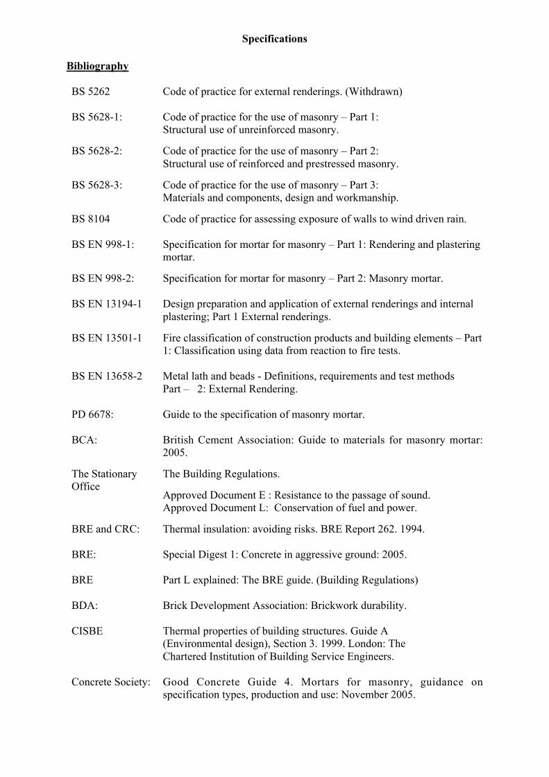
Bibliography
BS 5262 Code of practice for external renderings. (Withdrawn)
BS 5628-1: Code of practice for the use of masonry – Part 1:Structural use of unreinforced masonry.
BS 5628-2: Code of practice for the use of masonry – Part 2:Structural use of reinforced and prestressed masonry.
BS 5628-3: Code of practice for the use of masonry – Part 3:Materials and components, design and workmanship.
BS 8104 Code of practice for assessing exposure of walls to wind driven rain.
BS EN 998-1: Specification for mortar for masonry – Part 1: Rendering and plasteringmortar.
BS EN 998-2: Specification for mortar for masonry – Part 2: Masonry mortar.
BS EN 13194-1 Design preparation and application of external renderings and internalplastering; Part 1 External renderings.
BS EN 13501-1 Fire classification of construction products and building elements – Part1: Classification using data from reaction to fire tests.
BS EN 13658-2 Metal lath and beads - Definitions, requirements and test methodsPart – 2: External Rendering.
PD 6678: Guide to the specification of masonry mortar.
BCA: British Cement Association: Guide to materials for masonry mortar:2005.
The StationaryOffice
The Building Regulations.
Approved Document E : Resistance to the passage of sound.Approved Document L: Conservation of fuel and power.
BRE and CRC: Thermal insulation: avoiding risks. BRE Report 262. 1994.
BRE: Special Digest 1: Concrete in aggressive ground: 2005.
BRE Part L explained: The BRE guide. (Building Regulations)
BDA: Brick Development Association: Brickwork durability.
CISBE Thermal properties of building structures. Guide A(Environmental design), Section 3. 1999. London: TheChartered Institution of Building Service Engineers.
Concrete Society: Good Concrete Guide 4. Mortars for masonry, guidance onspecification types, production and use: November 2005.
Specifications
Macintosh HD:Users:jennycarr:Desktop:extras:LT - Specifications #47E93A.doc Page 20 of 2124thApril 2007
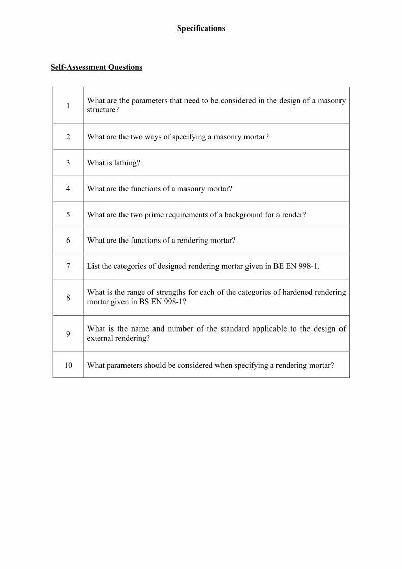
Self-Assessment Questions
1What are the parameters that need to be considered in the design of a masonrystructure?
2 What are the two ways of specifying a masonry mortar?
3 What is lathing?
4 What are the functions of a masonry mortar?
5 What are the two prime requirements of a background for a render?
6 What are the functions of a rendering mortar?
7 List the categories of designed rendering mortar given in BE EN 998-1.
8What is the range of strengths for each of the categories of hardened renderingmortar given in BS EN 998-1?
9What is the name and number of the standard applicable to the design ofexternal rendering?
10 What parameters should be considered when specifying a rendering mortar?
Specifications
Macintosh HD:Users:jennycarr:Desktop:extras:LT - Specifications #47E93A.doc Page 21 of 2124thApril 2007
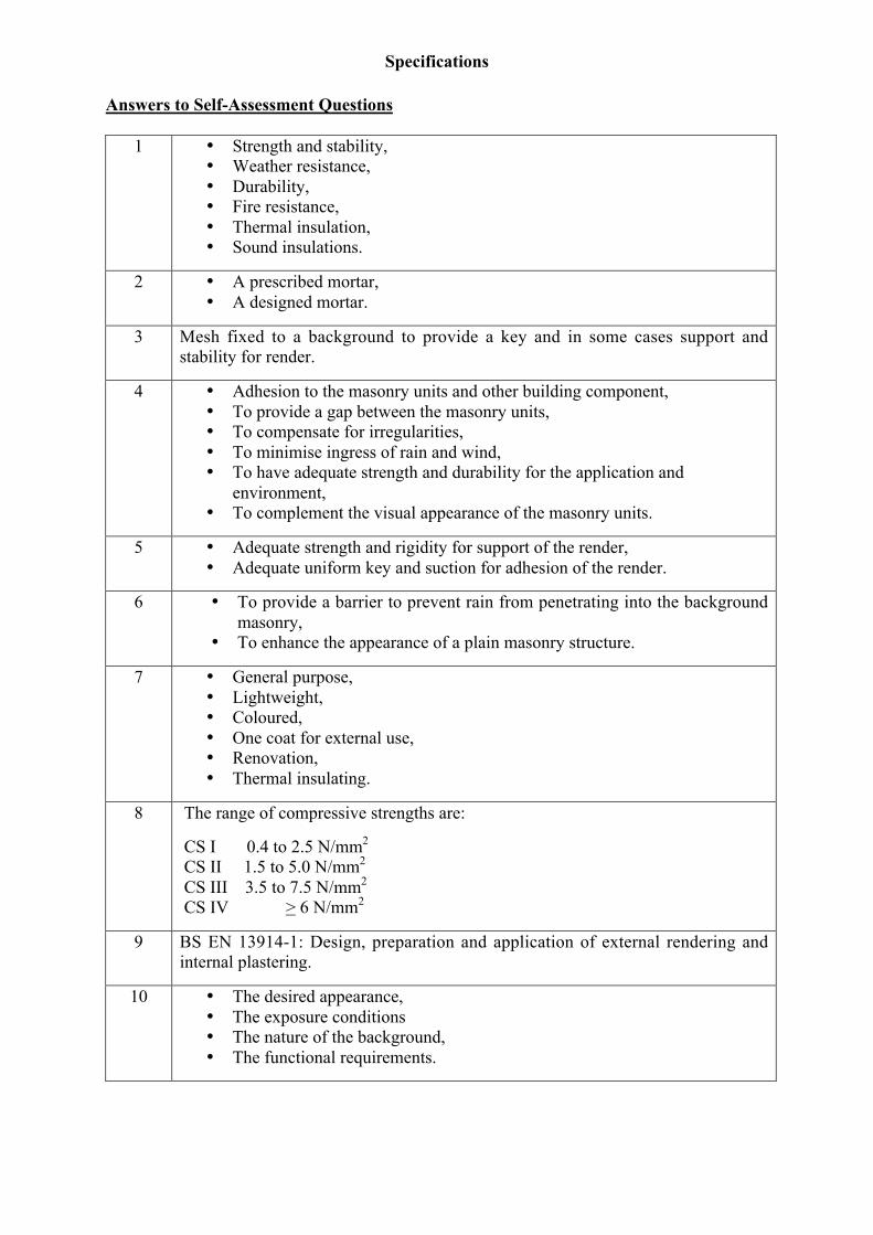
Answers to Self-Assessment Questions
1 • Strength and stability,• Weather resistance,• Durability,• Fire resistance,• Thermal insulation,• Sound insulations.
2 • A prescribed mortar,• A designed mortar.
3 Mesh fixed to a background to provide a key and in some cases support andstability for render.
4 • Adhesion to the masonry units and other building component,• To provide a gap between the masonry units,• To compensate for irregularities,• To minimise ingress of rain and wind,• To have adequate strength and durability for the application and
environment,• To complement the visual appearance of the masonry units.
5 • Adequate strength and rigidity for support of the render,• Adequate uniform key and suction for adhesion of the render.
6 • To provide a barrier to prevent rain from penetrating into the backgroundmasonry,
• To enhance the appearance of a plain masonry structure.
7 • General purpose,• Lightweight,• Coloured,• One coat for external use,• Renovation,• Thermal insulating.
8 The range of compressive strengths are:
CS I 0.4 to 2.5 N/mm2
CS II 1.5 to 5.0 N/mm2
CS III 3.5 to 7.5 N/mm2
CS IV > 6 N/mm2
9 BS EN 13914-1: Design, preparation and application of external rendering andinternal plastering.
10 • The desired appearance,• The exposure conditions• The nature of the background,• The functional requirements.