learn the basics of hrsg inspection
TRANSCRIPT

8/4/2019 Learn the Basics of HRSG Inspection
http://slidepdf.com/reader/full/learn-the-basics-of-hrsg-inspection 1/25
2 COMBINED CYCLE JOURNAL, Third Quarter 2008
SPECIAL ISSUE: OUTAGE HANDBOOK HEAT-RECOVERY STEAM GENERATORS
The global economic downturnwill impose new challenges onplant operations. It’s difficult tobelieve that you will be asked
to do more with a smaller budget,but you will. However, approaching
these new challenges with a positivemindset can yield significant ben-efits. One might be that your juniorstaff is forced to learn more aboutpower-generation processes, equip-ment, and systems, thereby increas-ing the level of expertise onsite.
An area of possible cost-cuttingat some gas-turbine-based cogen-eration and combined-cycle plantsis in heat-recovery steam generator(HRSG) inspection. Developing on-staff capability to conduct base-levelHRSG inspections saves both moneyand the need to schedule yet anotherservice organization into an alreadycomplex outage matrix.
Most plants have considerable gas-and steam-turbine expertise but manydo not have on-staff experts for HRSGsand generators. Developing HRSGknow-how begins with understandingthe types of degradation/damage thatcan occur and where to lookfor each.
To compile the check-list that follows, the editorsattended the HRSG Acad-emy conducted by HRSTInc, Eden Prairie, Minn.The engineering services
firm focuses on inspection,training, O&M, and redesignprojects for this special classof steam generators. It con-ducts two “academies” annu-ally in North America andperiodically in internationallocations. Each hosts up to50 to 60 “students,” the max-imum practical class size toassure constructive interac-tion among lecturers andattendees while allowing allan opportunity to have theirquestions answered.
The HRSG Academy may
be the best program in the industryfor teaching plant personnel the fun-damentals of heat-recovery steamgenerators. A graduate who laterbecomes his or her plant’s resident“expert” on HRSGs is likely to attend
the Academy a second time—to diginto specifics. Think of Shakespearehere: You can’t possibly understandand absorb everything in one pass, oreven two.
The segment of the academy pro-gram dealing with HRSG inspec-tion was “taught” by Lester Stanley,Scott Wambeke, and Amy Sieben,all licensed professional engineerswith a wealth of experience in HRSGdesign, inspection, and trouble-shooting. Their course covered bothonline and offline inspection. Thefirst encompassed data review tasksconducted in and around the controlroom and field tasks requiring a unitwalk-down. Offline inspection wasdivided into gas-side, exterior, anddrums. Also included was a primeron nondestructive examination(NDE) techniques and on sampling of deposits and pressure parts.
Onlineinspection
Stanley opened the online segment of
the program by stating its goals:n Identify poor operating practices.n Identify areas requiring attention
when plant operation permits anoffline inspection and/or duringthe next maintenance outage.
Data review tasksThe best place to begin your inspec-tion, the three instructors agreed, isin the control center where you haveaccess to personnel familiar with theplant’s operational idiosyncrasies aswell as to historical data. This inves-tigative work generally is done whilethe unit is operating to be sure it doesnot impact outage duration. HRSTuses a basic 10-point checklist forthe data-review task, but items maybe added and/or deleted dependingon plant design and other consider-ations.
1. Feedwater control. Threeof the many questions youshould ask operations per-sonnel are these:n Do you see large fluc-tuations in feedwater flowduring “steady-state” opera-tion?
n Does feedwater flow startand stop frequently duringstartup?n During overnight shut-downs, is there frequent“topping-off” of the drum tomaintain level?
A “yes” answer to one ormore of the questions meansthere’s risk of thermal-shockdamage—especially in thecoldest tube panel. Theseactions cause thermal-stressevents to economizers andfeedwater heaters within
the HRSG. The number and
Learn the basics of HRSG inspection
Learned at HRST Inc’s
Next session: Jan 27-29, 2009Marco Polo Beach Resort, Miami
Details at www.hrstinc.com

8/4/2019 Learn the Basics of HRSG Inspection
http://slidepdf.com/reader/full/learn-the-basics-of-hrsg-inspection 2/25
www.shawgrp.com
ENGINEERING • DESIGN • PROCUREMENT • CONSTRUCTION • COAL • GAS
GEOTHERMAL • AIR QUALITY CONTROL • POWER GENERATION SERVICES
SHAW POWER GROUP, FOSSIL DIVISION
At Shaw, we build more than state-of-the-art power plants. We also build win-win
working relationships with our clients that focus on one thing: successful project
completion. As the industry turns to natural gas for clean, reliable power, you
can turn to Shaw for on-target project execution. We deliver what you expect.
You can count on it.
Count On Powerful Relationships
4M022008D
_ _ _
8/4/2019 Learn the Basics of HRSG Inspection
http://slidepdf.com/reader/full/learn-the-basics-of-hrsg-inspection 3/25
4 COMBINED CYCLE JOURNAL, Third Quarter 2008
SPECIAL ISSUE: OUTAGE HANDBOOK HEAT-RECOVERY STEAM GENERATORS
duration of events influences howquickly tube leaks and cracking willoccur.
2. Steam drums. First thing toinvestigate is the consistency amongdrum-level transmitters, level gages,and probe indicators.
If all are not in agreement, con-
sider checking the calibration meth-od and the pressure andtemperature compensationsettings for the level trans-mitter.
Don’t overlook askingif the “agreement” amonglevel indicators differs athigh and low steam loadsand/or high and low drumlevels. Stanley said thatHRST often inspects high-pressure (HP) drums withwater-level marks that areseveral inches too high, yet
the operators say they are controllingto the OEM’s guidelines. This meansthere is disagreement between theindicated and actual drum levels.
Concern here is that if the opera-tors experience a high-drum-levelevent, they may think they’re operat-ing below the “high-high” level (HHL)but are actually above it and drumwater may be carrying-over into theHP superheater.
Wambeke mentioned, “You now seethat the value of a thorough annualinspection goes well beyond identi-fying wear and tear that requiresrepair. It enables the operationsteam to see what’s really going on inthe HRSG and suggests fine-tuningof controls and procedures to avoidincidents that can damage equip-ment unnecessarily.”
Stanley continued, “Ask if therates of pressure increase and/ordecrease during startup and shut-down exceed OEM guidelines.” If “yes,” you should be concerned aboutthe possibility of fatigue damage atmanways and thick nozzles and care-fully check those locations when theunit is out of service.
HRST engineers are seeing more
and more HRSGs with crack indica-tions on downcomer nozzle welds,supporting what many in the indus-try have been saying for years: HP-drum nozzles are high on the listof components most susceptible tocycling stresses.
Sieben added that spin coolingis hard on the HRSG too. “Mostoperations personnel don’t seem toapproach shutdowns as carefully asthey do startups,” she said, “and afast cool-down can be just as damag-ing as a fast start.”
3. Desuperheaters get a significant
amount of podium time in virtually
every HRST presentation on boilerhealth. Poor design, leaking valves,ineffective spray nozzles, a lack of instrumentation, and other factorscan wreak havoc at cogenerationand combined-cycle plants, puttingpersonnel safety at risk and causingequipment damage that should never
occur.
One of the first things to inves-tigate is spray-valve behavior. Isspray-valve position near constantat steady load or does it fluctuate— sometimes closing entirely? If yourspray valve is continually hunting— that is, opening and closing dozens of times each hour—the hot/cold cycleseventually will stress desuperheaternozzles to failure and possibly createother damage as well. Control-logicadjustments generally can rectifythis condition.
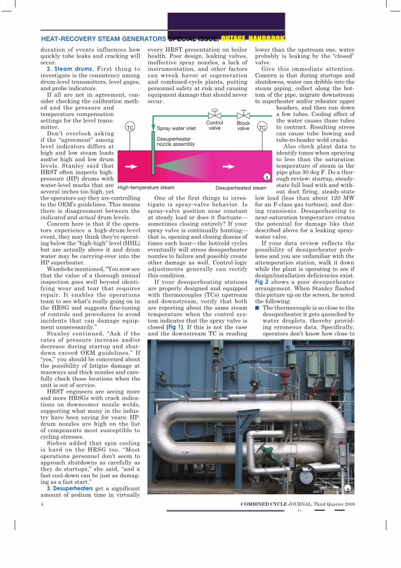
If your desuperheating stationsare properly designed and equippedwith thermocouples (TCs) upstreamand downstream, verify that bothare reporting about the same steamtemperature when the control sys-tem indicates that the spray valve isclosed (Fig 1). If this is not the caseand the downstream TC is reading
lower than the upstream one, waterprobably is leaking by the “closed”valve.
Give this immediate attention.Concern is that during startups andshutdowns, water can dribble into thesteam piping, collect along the bot-tom of the pipe, migrate downstream
to superheater and/or reheater upperheaders, and then run downa few tubes. Cooling effect of the water causes those tubesto contract. Resulting stresscan cause tube bowing andtube-to-header weld cracks.
Also check plant data toidentify times when sprayingto less than the saturationtemperature of steam in thepipe plus 30 deg F. Do a thor-ough review: startup, steady-state full load with and with-out duct firing, steady-state
low load (less than about 120 MWfor an F-class gas turbine), and dur-ing transients. Desuperheating tonear-saturation temperature createsthe potential for damage like thatdescribed above for a leaking spray-water valve.
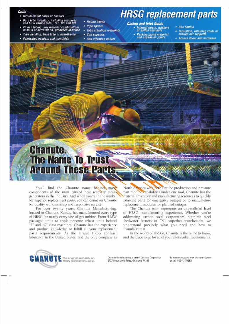
If your data review reflects thepossibility of desuperheater prob-lems and you are unfamiliar with theattemperation station, walk it downwhile the plant is operating to see if design/installation deficiencies exist.Fig 2 shows a poor desuperheaterarrangement. When Stanley flashedthis picture up on the screen, he notedthe following:n The thermocouple is so close to the
desuperheater it gets quenched bywater droplets, thereby provid-ing erroneous data. Specifically,operators don’t know how close to
Desuperheaternozzle assembly
Spray water inletControlvalve
Blockvalve
High-temperature steam Desuperheated steam
1
TC TC
Upstream elbowsThermocouple
No drain or drip leg at low point
Desuperheater
2
8/4/2019 Learn the Basics of HRSG Inspection
http://slidepdf.com/reader/full/learn-the-basics-of-hrsg-inspection 4/25
8/4/2019 Learn the Basics of HRSG Inspection
http://slidepdf.com/reader/full/learn-the-basics-of-hrsg-inspection 5/25
6 COMBINED CYCLE JOURNAL, Third Quarter 2008
SPECIAL ISSUE: OUTAGE HANDBOOK HEAT-RECOVERY STEAM GENERATORS
saturation temperature that theplant is operating. An improvedpipe location for the TC is needed.
n The desuperheater is too closeto both the upstream and down-stream pipe elbows. Problems cre-ated: Steam flow to the attempera-tor is not uniform and spray water
is not fully evaporated beforeimpinging on the downstreamelbow. Latter causes fatigue dam-age to the elbow.
n There is no drain at the low point,allowing water to pool and to cre-ate “water events” during startup.4. Stack temperature. Recall that
high stack temperature is indicativeof inefficient operation. Compare theactual readings at high and low loadsand compare to known benchmarks. A large difference between the actualand known signals a problem. Checkcommon causes—such as debris
accumulation on finned-tube surfac-es—and take corrective action.
5. Water temperature at economizeroutlet. Compare the water tempera-ture at the economizer outlet to thesaturation temperature of water inthe steam drum at the exact sametime. If the two are within a couple of degrees, Wambeke said, then waterexiting the economizer containssteam. Avoid this condition withstartups that are as short as possibleand maintain economizer feedwaterflow. Venting appropriatedly duringfilling and startup also is important.
Keep in mind that air pocketsblock water flow and once a circuitis blocked it will steam up, makingit even more difficult to “clear” dur-ing startup. If the temperature of thewater at the economizer outlet makesseveral sudden jumps upward duringstartup from a lower-than-expectedvalue, this generally means a vaporpockets are being cleared and normaloperation is being restored. However,such clearing events, similar to waterhammer, stress the economizerunnecessarily.
Stanley also suggested that youcompare an operating point to a
known benchmark. A large differenceis cause for concern. Check for steam-ing, gas-side fouling, vapor lockingfrom trapped air, gas bypass, etc, andtake corrective action.
6. Water temperature at economizerinlet. Review data to identify any inci-dences of rapid temperature change(30 deg F/min, plus or minus) whenthe unit is in operation or offline.Such rapid change is viewed as athermal shock to the economizer. Also verify that the inlet tempera-ture doesn’t drop below 120F. Lowtemperature is the cause of dewpoint
condensation and tube wastage.
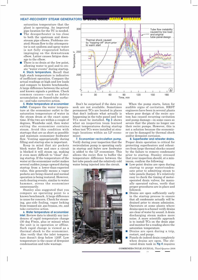
Don’t be surprised if the data youseek are not available. Sometimespermanent TCs are located in placesthat don’t indicate what actually ishappening in the tube panel and testTCs must be installed. Fig 3 showswhat an inspection team learnedabout temperatures during startupwhen test TCs were installed at stra-tegic locations within an LP econo-mizer.
7. Economizer recirculation pump. Verify during your inspection that therecirculation pump is operating earlyin startup and before new feedwateris added to the LP economizer. Thisallows the recirc flow to buffer thetemperature difference between thehot tube panels and the relatively coldwater being injected into the circuit.
When the pump starts, listen foraudible signs of cavitation. HRSTengineers have been in several plantswhere poor design of the recirc sys-tem has caused recurring cavitationand pump damage—in some cases sosevere that the plants no longer usetheir recirc pumps. However, this isnot a solution because the economiz-er can be damaged by thermal shockand/or dewpoint corrosion.
8. Superheater and reheater drains. Proper drain operation is critical forprotecting superheaters and reheat-ers from large thermal shocks causedby the failure to remove condensateprior to startup. Stanley stressedthat your inspection should, at a min-imum, confirm the following:n Low-point drains are open during
startup to purge water/conden-sate prior to admitting steam totube panels (harps). It’s relativelyeasy to check the timing of motor-operated drain valves; for manu-ally operated valves, verify thatproper procedures are in place andfollowed.
n Drains are open sufficiently early
in the startup process to ensurethat all condensate actually will bedrained prior to steam admission.Operators at some plants wheredrains open to a funnel verify drainsare clear of water by sound: A draindischarging steam makes morenoise. A more scientific approachis to install TCs on the drain pipeand monitor for a reading above thesaturation temperature.
n Drains are open during a trip,restart, and purge.
n Panels do indeed drain completelywhen drains are open. The ele-
vated drain tank in Fig 4 requires
Thermal shock causedby “topping-off” drum priorto warm start
Tube flow instabilitycaused by low loadand originaltube-panel design
0 30 60 90 120 150 180
Time, min
300
250
200
T e m p e r a t u r e ,
F
3
4

8/4/2019 Learn the Basics of HRSG Inspection
http://slidepdf.com/reader/full/learn-the-basics-of-hrsg-inspection 6/25
IT GENERATES ENOUGH POWER FOR A CITY
AND ENOUGH PROBLEMS FOR A CRISIS.
I T ’ S B E T T E R T O K N O W
It’s no secret—along with power, your turbines generate serious problems. Fortunately, our engineers have a
serious solution. It’s called VitalPointSM
—the first fluid assessment program designed exclusively for power generation
companies. With VitalPoint, you get the most advanced condition monitoring tools in the industry. If there’s a problem
that threatens your equipment or an opportunity to extend your oil’s lifespan, our diagnostics will find it. To learn
more, simply call 800-655-4473 and ask for a VitalPoint specialist. VitalPoint—cleaner energy, from the inside out.
LOS ANGELES, CA | CHICAGO, IL | LOUISV ILLE, K Y | ATLANTA, GA | HOUSTON, TX | MONTERREY, MEXICO | TOKYO, JAPAN
ADVANCED FLUID ASSESSMENT
SM
8/4/2019 Learn the Basics of HRSG Inspection
http://slidepdf.com/reader/full/learn-the-basics-of-hrsg-inspection 7/25
8 COMBINED CYCLE JOURNAL, Third Quarter 2008
SPECIAL ISSUE: OUTAGE HANDBOOK HEAT-RECOVERY STEAM GENERATORS
sufficient pressure in the drainsystem to push condensate up intothe vessel. Drain tanks located ina pit are better because they allowgravity draining.
Also check to see that HP, IP,and LP drains are not combined ina common collection pipe upstream
of the blowdown tank. Reason: Flowthrough the HP drains could forcewater back into the IP or LP systemif all the drains are open at the sametime. Guidelines for proper drainsystem design can be found in the“HRSG Users Handbook,” publishedby the HRSG User’s Group (details atwww.hrsgusers.org).
9. Selective catalytic reduction sys-tem. Compare historical ammoniaconsumption and outlet NOx read-ings. Rapid changes to NOx emis-sions or ammonia flow may iden-tify catalyst plugging or poisoning or
ammonia supply issues. Catalyst canbe plugged by insulation released byway of transition-duct failure; ammo-nia injection nozzles can be pluggedby contaminants in the reagent or byrust in lances; in oil-fired turbines,unburned fuel sprayed on catalystduring failed start attempts canignite later and sinter the catalyst.
10. Gas-side backpressure. Doesoverall HRSG backpressure comparewith OEM predictions? If not, whatsections have more backpressurethan predicted? If you can determinewhere backpressure is high, thenthe boiler inspection can investigatemore carefully during the next out-age. Gas-side cleaning of finned-tubesections is one solution. More proac-tive inlet-duct liner and insulationmaintenance may be another if foul-ing by insulation fibers is to blame.
Online field tasksSome key inspection tasks onlycan be done while the HRSG isoperating—identification of casinghotspots, for example. Here are fivethings Wambeke suggested that youshould be sure to accomplish during
your online walk-down:1. Check the supplementary firing
system. Look through all view portsto determine flame health and duct-burner condition. Bullet points belowprovide some guidance for this activ-ity based on HRST’s experience.n A flame length in excess of 12 ft
for an F-class HRSG is too long.Reason: Long flames, typicallycaused by low exhaust flow and/orpoor distribution of exhaust flowacross the burner, can “lick” tubesin the first panel and cause local-ized overheating.
n
A bushy flame is desirable—that
is, unless it is angled upwardor downward, which indicates aproblem with exhaust flow to thatportion of the burner.
n A bright yellow flame is good; dullorange indicates too little exhaustflow.
n Monitor CEMS data as supple-
mental firing is initiated and shutoff. Noticeable step changes inNOx and CO levels may indicate aburner problem.
n Check the integrity of burner ele-ments and baffles. If breakageoccurs, there is the possibility of damage to firing-duct walls andfloors and to downstream tubebundles.2. Watch for deflection of superheater
and reheater floor pipe penetrationsduring startup and shutdown. Tempera-ture differentials across superheaterand reheater tube bundles can cause
the panels to bow, exacerbatingdrain-line lateral movement. Drainsthat collide with the floor liner orcasing often suffer stress-inducedcracking.
Stainless-steel bellows have dif-ficulty moving laterally, while fabricseals in high-temperature locationstypically stiffen-up. The extra motioncreated by panel bowing often causesbellows to crack and tear. On fabricseals, bands pull lose and the fabrickinks. Latter creates small holes
and leaks that propagate into fabricblowouts.
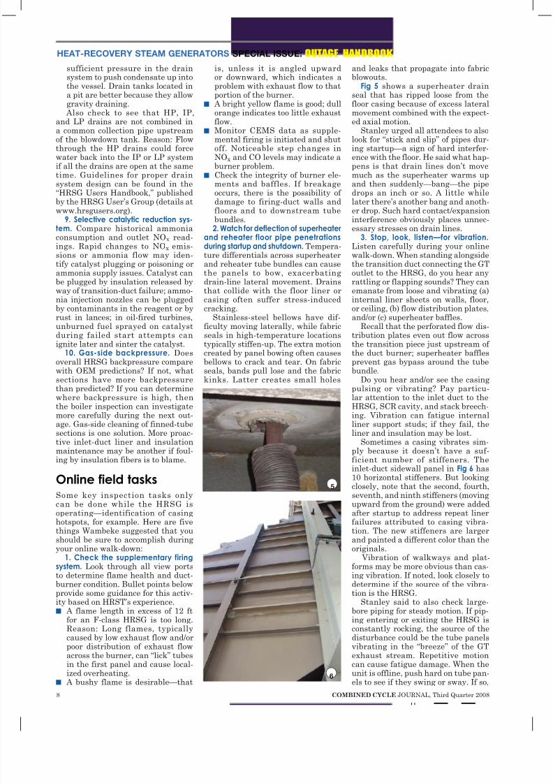
Fig 5 shows a superheater drainseal that has ripped loose from thefloor casing because of excess lateralmovement combined with the expect-ed axial motion.
Stanley urged all attendees to also
look for “stick and slip” of pipes dur-ing startup—a sign of hard interfer-ence with the floor. He said what hap-pens is that drain lines don’t movemuch as the superheater warms upand then suddenly—bang—the pipedrops an inch or so. A little whilelater there’s another bang and anoth-er drop. Such hard contact/expansioninterference obviously places unnec-essary stresses on drain lines.
3. Stop, look, listen—for vibration. Listen carefully during your onlinewalk-down. When standing alongsidethe transition duct connecting the GT
outlet to the HRSG, do you hear anyrattling or flapping sounds? They canemanate from loose and vibrating (a)internal liner sheets on walls, floor,or ceiling, (b) flow distribution plates,and/or (c) superheater baffles.
Recall that the perforated flow dis-tribution plates even out flow acrossthe transition piece just upstream of the duct burner; superheater bafflesprevent gas bypass around the tubebundle.
Do you hear and/or see the casingpulsing or vibrating? Pay particu-lar attention to the inlet duct to theHRSG, SCR cavity, and stack breech-ing. Vibration can fatigue internalliner support studs; if they fail, theliner and insulation may be lost.
Sometimes a casing vibrates sim-ply because it doesn’t have a suf-ficient number of stiffeners. Theinlet-duct sidewall panel in Fig 6 has10 horizontal stiffeners. But lookingclosely, note that the second, fourth,seventh, and ninth stiffeners (movingupward from the ground) were addedafter startup to address repeat linerfailures attributed to casing vibra-tion. The new stiffeners are largerand painted a different color than the
originals. Vibration of walkways and plat-
forms may be more obvious than cas-ing vibration. If noted, look closely todetermine if the source of the vibra-tion is the HRSG.
Stanley said to also check large-bore piping for steady motion. If pip-ing entering or exiting the HRSG isconstantly rocking, the source of thedisturbance could be the tube panelsvibrating in the “breeze” of the GTexhaust stream. Repetitive motioncan cause fatigue damage. When theunit is offline, push hard on tube pan-
els to see if they swing or sway. If so,
5
6

8/4/2019 Learn the Basics of HRSG Inspection
http://slidepdf.com/reader/full/learn-the-basics-of-hrsg-inspection 8/25
8/4/2019 Learn the Basics of HRSG Inspection
http://slidepdf.com/reader/full/learn-the-basics-of-hrsg-inspection 9/25
10 COMBINED CYCLE JOURNAL, Third Quarter 2008
SPECIAL ISSUE: OUTAGE HANDBOOK HEAT-RECOVERY STEAM GENERATORS
install better tube-panel restraintsand guides.
In some cases, sophisticated analy-sis is needed to determine the rootcause of vibration. A noise signa-ture often can help in this regard.Occasionally, vortex shedding inthe tube bundles can create acous-tic resonance problems. These maybe noticed near the HRSG and/or innearby buildings. Comparing calcu-lated and measured shedding fre-quencies can give clues.
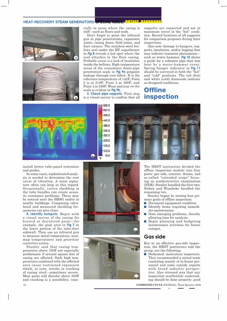
4. Identify hotspots. Begin witha visual survey of the casing forburned or discolored paint—for
example, the pink area in Fig 7 atthe lower portion of the inlet-ductsidewall. Then use an infrared gunto measure metal temperature; next,map temperatures and prioritizecorrective action.
Stanley said that casing tem-peratures above 350F are especiallyproblematic if several square feet of casing are affected. Such high tem-peratures combined with the affectedarea cause restrained expansionwhich, in turn, results in crackingof casing steel—sometimes severe.Most paint will discolor above 350F
and cracking is a possibility, espe-
cially in areas where the casing isstiff—such as floors and roofs.
Don’t forget to point the infraredgun at pipe penetrations, expansion joints, casing doors, field joints, andduct corners. The stainless-steel bel-lows seal under the HP superheaterin Fig 8 reveals a hot spot where the
seal attaches to the floor casing.Probable cause is a lack of insulationinside the bellows. High-temperatureareas of the economizer drain-pipepenetration seals in Fig 9a pinpointleakage through torn fabric. R is thereference temperature of 142F; Point2 is at 519F, Point 3 at 390F, andPoint 4 at 589F. Wear and tear on theseals is evident in Fig 9b.
5. Check pipe supports. First stepis a visual survey to confirm that all
supports are connected and not atmaximum travel in the “hot” condi-tion. Record locations of all supportsfor comparison purposes during laterinspections.
Also note damage to hangers, sup-ports, insulation, and/or lagging thatmay indicate transient phenomena—
such as water hammer. Fig 10 showsa guide for a reheater pipe that wasbent by a water-hammer event.Spring hanger indicator in Fig 11 should be surveyed in both the “hot”and “cold” positions. The red (hot)and white (cold) diamonds indicateas-designed conditions.
Offlineinspection
The HRST instructors divided theoffline inspection module into fourparts: gas side, exterior, drums, andso-called “extended scope” focus-ing on nondestructive examination(NDE). Stanley handled the first two;Sieben and Wambeke handled theremaining two.
Stanley began by stating four pri-mary goals of offline inspection:n Document equipment condition.n Identify items requiring immedi-
ate maintenance.n Note emerging problems, thereby
allowing time for analysis.n Begin planning and budgeting
maintenance activities for futureoutages.
Gas sideKey to an effective gas-side inspec-tion, the HRST instructors told thegroup, are the following:n Dedicated, meticulous inspectors.
They recommended a mixed teamconsisting mainly of in-house per-sonnel and some outside expertswith broad industry perspec-tive. Also stressed was that anyinspection worthwhile undertak-
ing should be done properly; good
7
8
9a 9b
10
11
8/4/2019 Learn the Basics of HRSG Inspection
http://slidepdf.com/reader/full/learn-the-basics-of-hrsg-inspection 10/25
ALLIED POWER GROUP PUTS SALES AND SERVICE IN SYNCHRONICITY.
alliedpg.com U N I T E D F O R P E R F O R M A N C E .
Product names, logos, brands, and other trademarks mentioned herein are the property of their respective trademark holders. These trademark holders are not
affiliated with Allied Power Group, nor do they sponsor or endorse any of the products, services or methods supplied or used by Allied Power Group.
ALLIED POWER GROUP IS YOUR ONE TRUSTED SOURCE FOR FAST REPAIRS AND HIGH-QUALITY REPLACEMENT PARTS. WE HAVE ONE OF
THE LARGEST GE AND WESTINGHOUSE INVENTORIES IN THE WORLD AND CAN PROVIDE FAST, HIGH QUALITY REPAIRS FOR IGT COMPONENTS SUCH
AS HOT GAS PATH AND COMBUSTION COMPONENTS FOR MAJOR OEMS. WITH FLEXIBLE OPTIONS LIKE EXCHANGE AND LOANER PROGRAMS,
CONSIGNMENT, SALES AND LEASE, INVENTORY MANAGEMENT AND POOLING, ALLIED POWER GROUP IS YOUR ONE-STOP SHOP. BEST OF ALL, WE
PROVIDE AN UNMATCHED LEVEL OF SERVICE WHEREVER AND WHENEVER YOU NEED IT TO KEEP YOUR BUSINESS RUNNING.
1 5 0 0 5 M i n t z L a n e, H o u s t o n, T X 7 70 1 4 1 . 8 8 8 . 8 3 0 . 3 5 3 5

8/4/2019 Learn the Basics of HRSG Inspection
http://slidepdf.com/reader/full/learn-the-basics-of-hrsg-inspection 11/25
12 COMBINED CYCLE JOURNAL, Third Quarter 2008
SPECIAL ISSUE: OUTAGE HANDBOOK HEAT-RECOVERY STEAM GENERATORS
inspections, Stanley continued,take days, not hours.
n A detailed record of observationsand other facts. Take plenty of pho-tos and measurements; describeobservations in detail using a digi-tal recorder and transcribing/edit-ing your voice notes. Critical mea-
surements might include materialthickness in areas experiencingFAC (flow accelerated corrosion)attack, length of any cracks iden-tified, distances across any cracksfound, etc.
n Organize facts logically. Linkevery fact to a specific locationin the HRSG. Editor’s note: Per-haps this goal can be facilitatedthrough use of software custom-ized for your specific boilers. Tolearn more, access www.combined-cyclejournal.com/archives.html,click 3Q/2007, click “Knowledge
retention: New software tools helpimprove plant reliability, reducemaintenance cost” on issue cover.
Your ultimate goal should be toprovide a comprehensive follow-up checklist with detailed notesso someone else can conduct nextyear’s inspection having the sameknowledge you possess—that is, topick up where you left off withoutmissing a beat.
n Recommend a follow-up NDE pro-gram for areas where problems aresuspected. This might include oneor more of the following: borescopeexamination, ultrasonic (UT) sur-veys, dye-penetrant (PT) testing,
magnetic-particle (MT) examina-tion, hardness testing (particu-larly where P91/T91 materials areused), etc.For inspection purposes, Stanley seg-
ments the HRSG into three areas:n Access lanes—including inlet
duct, firing duct, SCR, between
tube bundles, and stack.n Crawl spaces under and above
tube headers.n Exterior—including roof casing,
floor casing, walls. Your inspection should go beyond
what HRST would do under itsstandard HRSG contract. Engageother experts to examine your steamvalves, safety valves, silencers,instrumentation, piping to/from theHRSG, etc.
Inlet-duct checklist. Inspect theliner system for loose plates, spinningwashers, exposed insulation, and
failed studs. Fig 12 is typical of whatyou might find. Here studs failed andwashers were liberated leaving linerplates with minimal support. Once
a liner plate moves and a gap is cre-ated between it and adjacent plates,insulation can be sucked into the flowstream. This creates a hot spot in thetransition duct skin and allows liber-ated insulation to blind a portion of the SCR catalyst.
Be aware that problems often are
experienced with flow distributionplates. Also, check harps for corro-sion, warped tubes, and vibrationwear from tubes contacting—that is,banging into or rubbing against— each other when the unit is in ser-vice. Baffles and tube ties shouldbe inspected for vibration damage,wear, expansion interferences, andweld cracks.
Figs 13, 14 show failed tube-fin tabwelds that caused “rattling.” Somefailed tabs rub directly on tubes. Although no gouges were identifiedin this case, if condition is left uncor-
rected, tube wear will continue (tube-tie components are harder than thetube material). Such wear often isworst at lower elevations, which isconvenient because they are easier toaccess for inspection. Note that theinlet-duct superheater panel in Fig 15 is missing center baffles.
Firing-duct checklist has five focalpoints for your inspection:n Liner system. Inspect the same
way you did for the inlet duct.n Duct burner. Look for sag in ele-
ments or baffles, nozzle plugging,and coke buildup; verify thatburner “wing” condition is satis-factory.12
Studs broken;washers missing
13 14 15
16 17

8/4/2019 Learn the Basics of HRSG Inspection
http://slidepdf.com/reader/full/learn-the-basics-of-hrsg-inspection 12/25
Visit us at POWER-GEN International, Booth #2112.
O f f i c e s i n : N ort h A m e r i c a • La t i n A m e r i c a • E u rope • A s i a
I I I I
REMOTE
EtaPRO™
IT I G E ICE
“ The system allows us to respond quickly to changes in component
performance, before they impact plant heat rate.” — Chung Liu, Massachusetts Municipal Wholesale Electric Company
www.etaproefficiency.com
800.803.6737
EtaPRO ™ Performance Monitoring and Optimization System saves money while reducing
emissions. With 600+ generating units worldwide, General Physics Corporation’s real-time
monitoring helps plants achieve a
and typically provides a 100% ROI in less than 12 months. From installation to operation,
our power plant experts partner with you and respond quickly whenever you need them.
Put our experience to work for you.
Energy
1% or better heat rate improvement
Visit us at HRSG, Booth 716
8/4/2019 Learn the Basics of HRSG Inspection
http://slidepdf.com/reader/full/learn-the-basics-of-hrsg-inspection 13/25
14 COMBINED CYCLE JOURNAL, Third Quarter 2008
SPECIAL ISSUE: OUTAGE HANDBOOK HEAT-RECOVERY STEAM GENERATORS
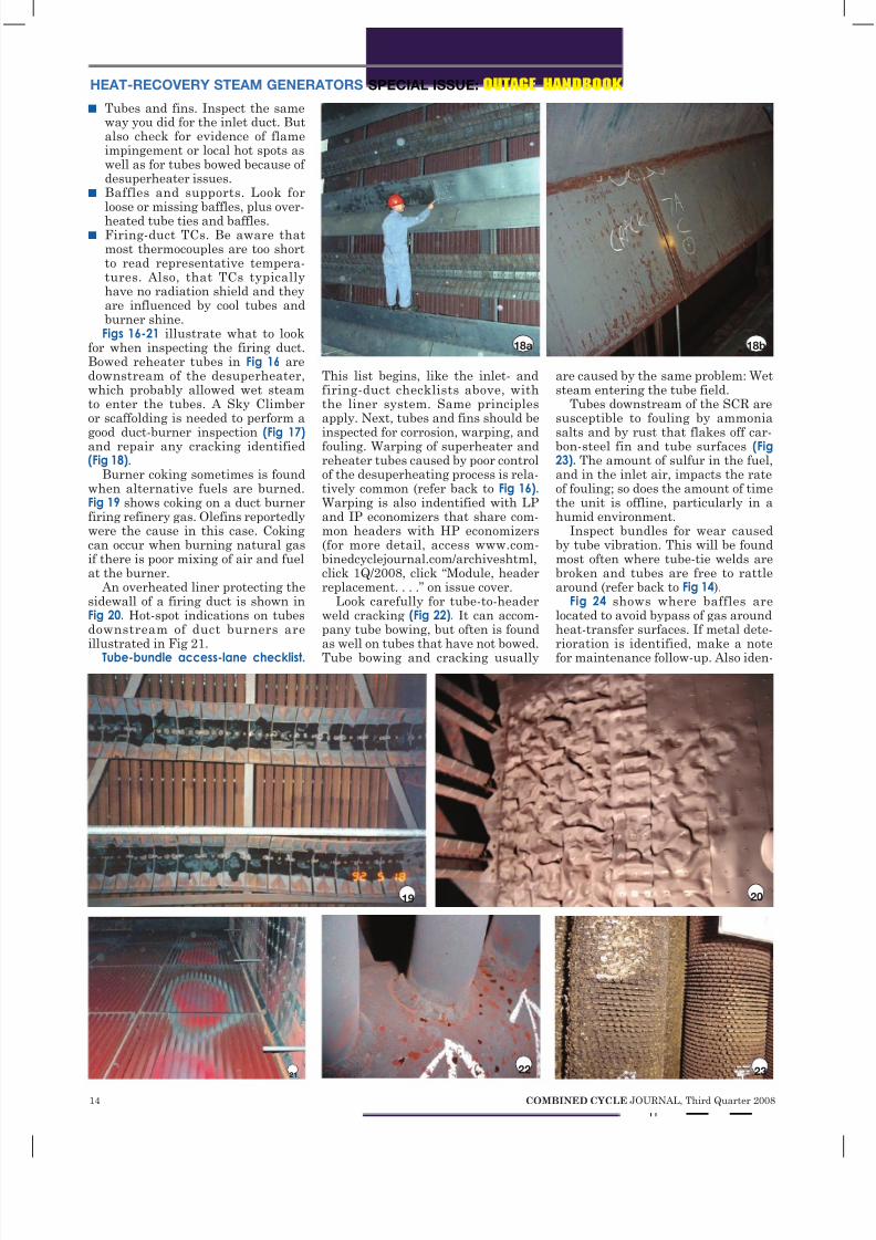
n Tubes and fins. Inspect the sameway you did for the inlet duct. Butalso check for evidence of flameimpingement or local hot spots aswell as for tubes bowed because of desuperheater issues.
n Baffles and supports. Look forloose or missing baffles, plus over-
heated tube ties and baffles.n Firing-duct TCs. Be aware that
most thermocouples are too shortto read representative tempera-tures. Also, that TCs typicallyhave no radiation shield and theyare influenced by cool tubes andburner shine.Figs 16-21 illustrate what to look
for when inspecting the firing duct.Bowed reheater tubes in Fig 16 aredownstream of the desuperheater,which probably allowed wet steamto enter the tubes. A Sky Climberor scaffolding is needed to perform a
good duct-burner inspection (Fig 17) and repair any cracking identified(Fig 18).
Burner coking sometimes is foundwhen alternative fuels are burned.Fig 19 shows coking on a duct burnerfiring refinery gas. Olefins reportedlywere the cause in this case. Cokingcan occur when burning natural gasif there is poor mixing of air and fuelat the burner.
An overheated liner protecting thesidewall of a firing duct is shown inFig 20. Hot-spot indications on tubesdownstream of duct burners areillustrated in Fig 21.
Tube-bundle access-lane checklist.
This list begins, like the inlet- andfiring-duct checklists above, withthe liner system. Same principlesapply. Next, tubes and fins should be
inspected for corrosion, warping, andfouling. Warping of superheater andreheater tubes caused by poor controlof the desuperheating process is rela-tively common (refer back to Fig 16). Warping is also indentified with LPand IP economizers that share com-mon headers with HP economizers(for more detail, access www.com-binedcyclejournal.com/archiveshtml,click 1Q/2008, click “Module, headerreplacement. . . .” on issue cover.
Look carefully for tube-to-headerweld cracking (Fig 22). It can accom-pany tube bowing, but often is foundas well on tubes that have not bowed.Tube bowing and cracking usually
are caused by the same problem: Wetsteam entering the tube field.
Tubes downstream of the SCR aresusceptible to fouling by ammonia
salts and by rust that flakes off car-bon-steel fin and tube surfaces (Fig23). The amount of sulfur in the fuel,and in the inlet air, impacts the rateof fouling; so does the amount of timethe unit is offline, particularly in ahumid environment.
Inspect bundles for wear causedby tube vibration. This will be foundmost often where tube-tie welds arebroken and tubes are free to rattlearound (refer back to Fig 14).
Fig 24 shows where baffles arelocated to avoid bypass of gas aroundheat-transfer surfaces. If metal dete-rioration is identified, make a notefor maintenance follow-up. Also iden-
18a 18b
19 20
2122 23

8/4/2019 Learn the Basics of HRSG Inspection
http://slidepdf.com/reader/full/learn-the-basics-of-hrsg-inspection 14/25
8/4/2019 Learn the Basics of HRSG Inspection
http://slidepdf.com/reader/full/learn-the-basics-of-hrsg-inspection 15/25
16 COMBINED CYCLE JOURNAL, Third Quarter 2008
SPECIAL ISSUE: OUTAGE HANDBOOK HEAT-RECOVERY STEAM GENERATORS
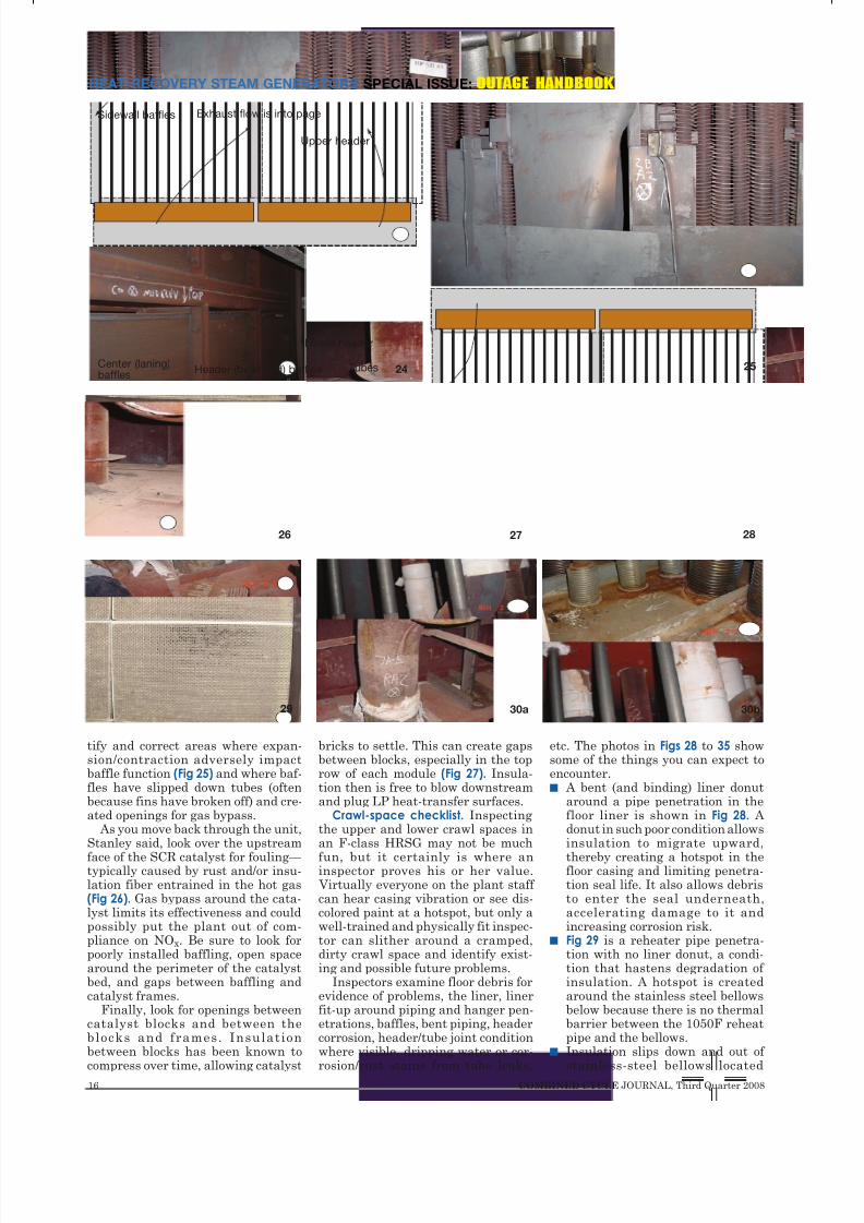
tify and correct areas where expan-sion/contraction adversely impactbaffle function (Fig 25) and where baf-fles have slipped down tubes (oftenbecause fins have broken off) and cre-ated openings for gas bypass.
As you move back through the unit,Stanley said, look over the upstream
face of the SCR catalyst for fouling— typically caused by rust and/or insu-lation fiber entrained in the hot gas(Fig 26). Gas bypass around the cata-lyst limits its effectiveness and couldpossibly put the plant out of com-pliance on NOx. Be sure to look forpoorly installed baffling, open spacearound the perimeter of the catalystbed, and gaps between baffling andcatalyst frames.
Finally, look for openings betweencatalyst blocks and between theblocks and frames. Insulationbetween blocks has been known to
compress over time, allowing catalyst
bricks to settle. This can create gapsbetween blocks, especially in the toprow of each module (Fig 27). Insula-tion then is free to blow downstreamand plug LP heat-transfer surfaces.
Crawl-space checklist. Inspectingthe upper and lower crawl spaces inan F-class HRSG may not be much
fun, but it certainly is where aninspector proves his or her value. Virtually everyone on the plant staff can hear casing vibration or see dis-colored paint at a hotspot, but only awell-trained and physically fit inspec-tor can slither around a cramped,dirty crawl space and identify exist-ing and possible future problems.
Inspectors examine floor debris forevidence of problems, the liner, linerfit-up around piping and hanger pen-etrations, baffles, bent piping, headercorrosion, header/tube joint conditionwhere visible, dripping water or cor-
rosion/rust stains from tube leaks,
etc. The photos in Figs 28 to 35 showsome of the things you can expect toencounter.n A bent (and binding) liner donut
around a pipe penetration in thefloor liner is shown in Fig 28. A donut in such poor condition allowsinsulation to migrate upward,
thereby creating a hotspot in thefloor casing and limiting penetra-tion seal life. It also allows debristo enter the seal underneath,accelerating damage to it andincreasing corrosion risk.
n Fig 29 is a reheater pipe penetra-tion with no liner donut, a condi-tion that hastens degradation of insulation. A hotspot is createdaround the stainless steel bellowsbelow because there is no thermalbarrier between the 1050F reheatpipe and the bellows.
n Insulation slips down and out of
stainless-steel bellows located
Exhaust flow is into pageSidewall baffles
Center (laning)baffles
TubesHeader (bulkhead) baffles
Lower header
Upper header
24 25
26 27 28
29 30b30a

8/4/2019 Learn the Basics of HRSG Inspection
http://slidepdf.com/reader/full/learn-the-basics-of-hrsg-inspection 16/25
COMBINED CYCLE JOURNAL, Third Quarter 2008 17

8/4/2019 Learn the Basics of HRSG Inspection
http://slidepdf.com/reader/full/learn-the-basics-of-hrsg-inspection 17/25
18 COMBINED CYCLE JOURNAL, Third Quarter 2008
SPECIAL ISSUE: OUTAGE HANDBOOK HEAT-RECOVERY STEAM GENERATORS
above roof casing because no linerdonut is present (Fig 30a). Roof-topphoto reveals casing rust and bluetint to bellows indicative of opera-tional hotspots (Fig 30b).
n Drain pipes under HP superheat-ers and reheaters are notoriousfor developing stress cracks— especially at the drain pipe-to- jumper weld (Fig 31a). Inspector’sfinger points to what he believesis a crack (Fig 31b), later confirmedwith dye-penetrant test.
n Debris accumulation on roof allowsrainwater to pool (Fig 32a), leadingto corrosion problems inside theHRSG. The result of long periodsoffline and water leakage is shownin (Fig 32b).
n Poor condition of drain line serv-
ing an LP economizer was found
during an inspection of the lowercrawl space below this HRSG(Fig 33a). HRST engineers recom-mended removing the stainless-steel bellows expansion joint
around this drain, which had lostabout 25% of its wall thickness infive years of service (Fig 33B).
n Gas bypass: Rust is swept away inregion of high gas velocity down-stream of the small square darkopening in Fig 34.
n Oversize gaps, which proper bafflingshould prevent, may avoid interfer-ence problems but they adverselyimpact performance (Fig 35).
Exterior inspectionBy this point in the session, attendees
were catching on to what they should
be looking for when inspecting anHRSG. The checklist presented forthis module had a familiar ring:n Casing hotspots and cracking.n Piping penetration seals.n Access-door condition.n Pipe hangers.n Expansion joints at the round-to-
square transition and between theHRSG and stack.
n HRSG foundations.Of course, this isn’t all you should
be inspecting on the exterior of yourHRSG. Time limitations in the class-room and space limitations in themagazine militate against coveringeverything. When developing aninspection program customized toyour plant, don’t forget such thingsas burner hardware, valves, safetyvalves and silencers, drum instru-mentation, ammonia vaporizer,ammonia injection grid and associ-
ated piping and nozzles, etc.Once again, photos taken during
inspections conducted by HRST engi-neers give you a good sense of what’simportant:n Fig 36 shows hotspot on access door
and adjacent casing caused byleaking door seal and/or problemswith the internal insulation pil-low.
n Rust that accumulates in a fabricseal impedes its ability to flex andeventually the material splits (Fig37). Liner donuts that are main-tained in good condition help pre-vent rust from dropping into theseal.
n Cracked stainless-steel bellowsin Fig 38 is a casualty of excessivedrain movement as discussed ear-
31a 31b
32a 32b
33a 33b
34
Opening
35
Gap
36
37

8/4/2019 Learn the Basics of HRSG Inspection
http://slidepdf.com/reader/full/learn-the-basics-of-hrsg-inspection 18/25
GE Energy
Worldwide serviceis in your reach.
GE Energy’s aeroderivative services
arelocated where youneed them—
anywhere in the world. Our service
centers arepositionedaroundthe globe,
ready to provide a full array of services
for industrial andmarine customers.
We also have an established network
of international field service teams who
can deliver the technological expertise
you expect from GE right to your site.No matter where you are, the aero
energy service team is there to help you
reach your goal.
Visit us at ge.com/energy
and findout more.
Service capabilities include contractual service agreements, engine and module exchange programs, spare parts,
modules and engines, repair and overhaul capability and engineering services both in the field and from the factory.
8/4/2019 Learn the Basics of HRSG Inspection
http://slidepdf.com/reader/full/learn-the-basics-of-hrsg-inspection 19/25
20 COMBINED CYCLE JOURNAL, Third Quarter 2008
SPECIAL ISSUE: OUTAGE HANDBOOK HEAT-RECOVERY STEAM GENERATORS
lier. Mechanical seals are an alter-native to fabric seals and bellows.
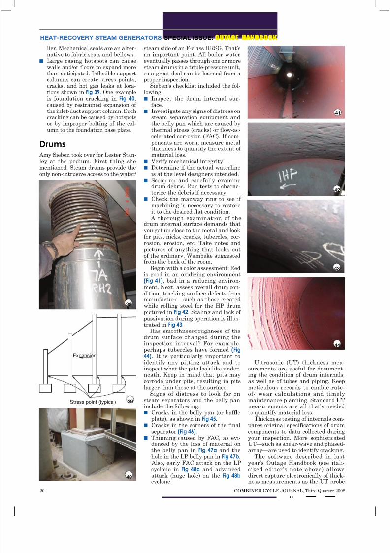
n Large casing hotspots can causewalls and/or floors to expand morethan anticipated. Inflexible supportcolumns can create stress points,cracks, and hot gas leaks at loca-tions shown in Fig 39. One example
is foundation cracking in Fig 40,caused by restrained expansion of the inlet-duct support column. Suchcracking can be caused by hotspotsor by improper bolting of the col-umn to the foundation base plate.
Drums Amy Sieben took over for Lester Stan-ley at the podium. First thing shementioned: Steam drums provide theonly non-intrusive access to the water/
steam side of an F-class HRSG. That’san important point. All boiler watereventually passes through one or moresteam drums in a triple-pressure unit,so a great deal can be learned from aproper inspection.
Sieben’s checklist included the fol-lowing:n Inspect the drum internal sur-
face.n Investigate any signs of distress on
steam separation equipment andthe belly pan which are caused bythermal stress (cracks) or flow-ac-celerated corrosion (FAC). If com-ponents are worn, measure metalthickness to quantify the extent of material loss.
n Verify mechanical integrity.n Determine if the actual waterline
is at the level designers intended.n Scoop-up and carefully examine
drum debris. Run tests to charac-
terize the debris if necessary.n Check the manway ring to see if
machining is necessary to restoreit to the desired flat condition.
A thorough examination of thedrum internal surface demands thatyou get up close to the metal and lookfor pits, nicks, cracks, tubercles, cor-rosion, erosion, etc. Take notes andpictures of anything that looks outof the ordinary, Wambeke suggestedfrom the back of the room.
Begin with a color assessment: Redis good in an oxidizing environment(Fig 41), bad in a reducing environ-ment. Next, assess overall drum con-dition, tracking surface defects frommanufacture—such as those createdwhile rolling steel for the HP drumpictured in Fig 42. Scaling and lack of passivation during operation is illus-trated in Fig 43.
Has smoothness/roughness of thedrum surface changed during theinspection interval? For example,perhaps tubercles have formed (Fig44). It is particularly important toidentify any pitting attack and toinspect what the pits look like under-neath. Keep in mind that pits maycorrode under pits, resulting in pits
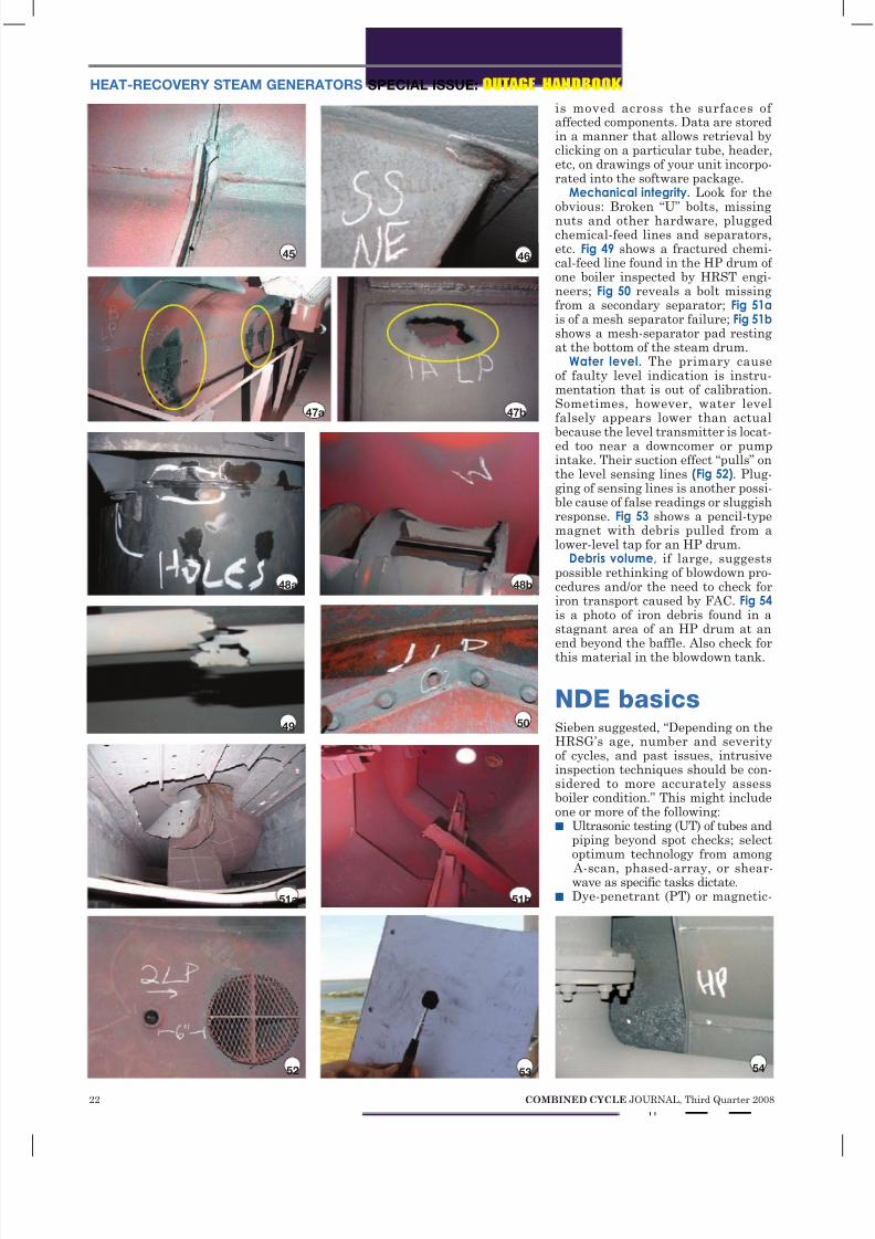
larger than those at the surface.Signs of distress to look for on
steam separators and the belly paninclude the following:n Cracks in the belly pan (or baffle
plate), as shown in Fig 45.n Cracks in the corners of the final
separator (Fig 46).n Thinning caused by FAC, as evi-
denced by the loss of material onthe belly pan in Fig 47a and thehole in the LP belly pan in Fig 47b. Also, early FAC attack on the LPcyclone in Fig 48a and advancedattack (huge hole) on the Fig 48b
cyclone.
Ultrasonic (UT) thickness mea-surements are useful for document-ing the condition of drum internals,as well as of tubes and piping. Keep
meticulous records to enable rate-of- wear calculations and timelymaintenance planning. Standard UTmeasurements are all that’s neededto quantify material loss.
Thickness testing of internals com-pares original specifications of drumcomponents to data collected duringyour inspection. More sophisticatedUT—such as shear-wave and phased-array—are used to identify cracking.
The software described in lastyear’s Outage Handbook (see itali-cized editor’s note above) allowsdirect capture electronically of thick-
ness measurements as the UT probe
38
Stress point (typical)
Expansion
39
40
41
42
43
44

8/4/2019 Learn the Basics of HRSG Inspection
http://slidepdf.com/reader/full/learn-the-basics-of-hrsg-inspection 20/25
FILTRATION
Turbine Lube Oil & EHC Solutions
Fluid Contamination Under Control with . . .
Innovative Filtration Products, Support and SolutionsMake Hy-Pro a part of your lube team and arm yourself with tools and
industry expertise to maximize reliability from your hydraulic & Lube assets.
Hy-Pro will help you develop and implement strategies to achieve and
maintain target fluid cleanliness levels and extend useful fluid life.
www.hyprofiltration.comFishers, Indiana USA. +1.317.849.3535
When gas turbines fall casualty to unit trips and fail-to-start
conditions, lube oil varnish is the usual suspect . . .
So how do you solve the problem? Electrostatic oil cleaners and depth filter
systems alone yield little or no long term success. While your unit is on-line and
the oil is warm, the majority of varnish-causing contaminants are in solution
and cannot be removed by electrostatic or depth filtration systems.
Hy-Pro has the solution to make varnish vanish . . .
And it doesn’t require electrostatic oil cleaning! Patent-pending Ion Charge
Bonding technology removes varnish-causing contaminants while they are
still in solution whether your turbine is on-line or standing by. Hy-Pro’s
soluble varnish removal system is the proven solution to restore and
maintain the health of your turbine oil!
Achieve & Maintain Target Varnish
Potential Numbers in Days not Months!
Dedicated Off-Line
Gearbox Filtration Duplex Filter, auto
kleen upgrade Vacuum Dehydration &
Turbine Oil Coalescence EHC & Lube Oil Filter
Element Upgrades.
Non-spark & static
dissipating elements.
before after
8/4/2019 Learn the Basics of HRSG Inspection
http://slidepdf.com/reader/full/learn-the-basics-of-hrsg-inspection 21/25
22 COMBINED CYCLE JOURNAL, Third Quarter 2008
SPECIAL ISSUE: OUTAGE HANDBOOK HEAT-RECOVERY STEAM GENERATORS
is moved across the surfaces of affected components. Data are storedin a manner that allows retrieval byclicking on a particular tube, header,etc, on drawings of your unit incorpo-rated into the software package.
Mechanical integrity. Look for theobvious: Broken “U” bolts, missing
nuts and other hardware, pluggedchemical-feed lines and separators,etc. Fig 49 shows a fractured chemi-cal-feed line found in the HP drum of one boiler inspected by HRST engi-neers; Fig 50 reveals a bolt missingfrom a secondary separator; Fig 51a is of a mesh separator failure; Fig 51b shows a mesh-separator pad restingat the bottom of the steam drum.
Water level. The primary causeof faulty level indication is instru-mentation that is out of calibration.Sometimes, however, water levelfalsely appears lower than actual
because the level transmitter is locat-ed too near a downcomer or pumpintake. Their suction effect “pulls” onthe level sensing lines (Fig 52). Plug-ging of sensing lines is another possi-ble cause of false readings or sluggishresponse. Fig 53 shows a pencil-typemagnet with debris pulled from alower-level tap for an HP drum.
Debris volume, if large, suggestspossible rethinking of blowdown pro-cedures and/or the need to check foriron transport caused by FAC. Fig 54 is a photo of iron debris found in astagnant area of an HP drum at anend beyond the baffle. Also check forthis material in the blowdown tank.
NDE basicsSieben suggested, “Depending on theHRSG’s age, number and severityof cycles, and past issues, intrusiveinspection techniques should be con-sidered to more accurately assessboiler condition.” This might includeone or more of the following:n Ultrasonic testing (UT) of tubes and
piping beyond spot checks; selectoptimum technology from among
A-scan, phased-array, or shear-wave as specific tasks dictate.
n Dye-penetrant (PT) or magnetic-
45 46
47a 47b
48a 48b
49 50
51a 51b
52 53 54

8/4/2019 Learn the Basics of HRSG Inspection
http://slidepdf.com/reader/full/learn-the-basics-of-hrsg-inspection 22/25
Wood Group Gas Turbine Services:
Ì Covers the world – where you work, we work
Ì Gives you OEM-equivalent MRO, cost-effectively
Ì Knows ongoing customer satisfaction is the real
meaning of “service”
Ì Delivers on its promises from beginning to end
We are centered on solving your rotating equipmentchallenges – and make sure your world keeps on turning.
Our solutions revolve
around a single point: You.
www.woodgroup.com/gts Ì [email protected]
8/4/2019 Learn the Basics of HRSG Inspection
http://slidepdf.com/reader/full/learn-the-basics-of-hrsg-inspection 23/25
24 COMBINED CYCLE JOURNAL, Third Quarter 2008
SPECIAL ISSUE: OUTAGE HANDBOOK HEAT-RECOVERY STEAM GENERATORS
55
particle (MT) testing of suspectareas.
n Removal and inspection of desu-perheaters.
n Borescope examination.n Sampling and analysis of pres-
sure-part materials.Ultrasonic testing. Recall how UT
works: An ultrasound transducerconnected to a diagnostic machine ispassed over the object being inspect-ed. The transducer typically is sepa-rated from the test object by a cou-plant. Reflection off the back wallor imperfection records thewall thickness or depth of the discontunity.
A-scan UT typically isselected for thickness test-ing, especially where FAC orexternal corrosion has beenidentified. It’s easy to use, fast,and accurate. Sieben offered an
inspection plan that’s easy tocustomize for your HRSGs. Shestressed that inspections shouldbe prioritized based on risk.n Examine LP evaporator circuits
(plus IP circuits up to 400-psigsaturated) and HP, IP, and LPeconomizer tubes that operatebetween 280F and 340F, the tem-perature range that exacerbatesFAC attack. Wall thinning gener-ally is experienced first after tubebends near the upper headers.
However, the risk of two-phaseFAC is just slightly higher thansingle-phase FAC, so the lower-header inlets may be more conve-nient to check. To access the tube-bend area, remove header bafflesas necessary.
n Check pipe elbows (jumpers) atthe apex of the elbow; and straightruns downstream of control valvesand orifice plates, especially wheretemperatures are more than 280Fand less than 340F.
n Examine headers on HRSGs with“stick-through” welds on the head-ers directly across from the tubeinlet. To review basics of tube-to-header joints, access www.com-
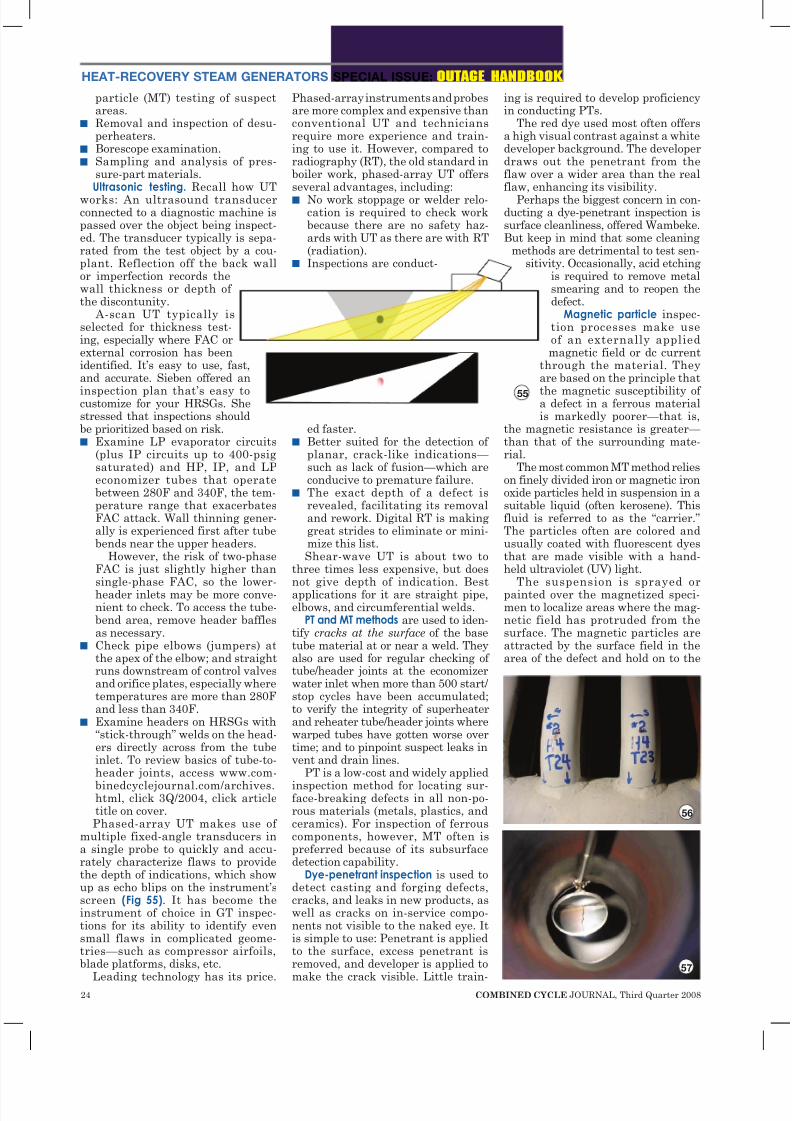
binedcyclejournal.com/archives.html, click 3Q/2004, click articletitle on cover.Phased-array UT makes use of
multiple fixed-angle transducers ina single probe to quickly and accu-rately characterize flaws to providethe depth of indications, which showup as echo blips on the instrument’sscreen (Fig 55). It has become theinstrument of choice in GT inspec-tions for its ability to identify evensmall flaws in complicated geome-tries—such as compressor airfoils,blade platforms, disks, etc.
Leading technology has its price.
Phased-array instruments and probesare more complex and expensive thanconventional UT and techniciansrequire more experience and train-ing to use it. However, compared toradiography (RT), the old standard inboiler work, phased-array UT offersseveral advantages, including:n No work stoppage or welder relo-
cation is required to check workbecause there are no safety haz-ards with UT as there are with RT(radiation).
n Inspections are conduct-
ed faster.n Better suited for the detection of
planar, crack-like indications— such as lack of fusion—which areconducive to premature failure.
n The exact depth of a defect isrevealed, facilitating its removaland rework. Digital RT is makinggreat strides to eliminate or mini-mize this list.Shear-wave UT is about two to
three times less expensive, but doesnot give depth of indication. Bestapplications for it are straight pipe,elbows, and circumferential welds.
PT and MT methods are used to iden-tify cracks at the surface of the basetube material at or near a weld. Theyalso are used for regular checking of tube/header joints at the economizerwater inlet when more than 500 start/stop cycles have been accumulated;to verify the integrity of superheaterand reheater tube/header joints wherewarped tubes have gotten worse overtime; and to pinpoint suspect leaks invent and drain lines.
PT is a low-cost and widely applied
inspection method for locating sur-face-breaking defects in all non-po-rous materials (metals, plastics, andceramics). For inspection of ferrouscomponents, however, MT often ispreferred because of its subsurfacedetection capability.
Dye-penetrant inspection is used todetect casting and forging defects,cracks, and leaks in new products, aswell as cracks on in-service compo-nents not visible to the naked eye. Itis simple to use: Penetrant is appliedto the surface, excess penetrant isremoved, and developer is applied to
make the crack visible. Little train-
ing is required to develop proficiencyin conducting PTs.
The red dye used most often offersa high visual contrast against a whitedeveloper background. The developerdraws out the penetrant from theflaw over a wider area than the realflaw, enhancing its visibility.
Perhaps the biggest concern in con-ducting a dye-penetrant inspection issurface cleanliness, offered Wambeke.But keep in mind that some cleaning
methods are detrimental to test sen-sitivity. Occasionally, acid etching
is required to remove metalsmearing and to reopen thedefect.
Magnetic particle inspec-tion processes make useof an externally appliedmagnetic field or dc current
through the material. Theyare based on the principle that
the magnetic susceptibility of a defect in a ferrous materialis markedly poorer—that is,
the magnetic resistance is greater— than that of the surrounding mate-rial.
The most common MT method relieson finely divided iron or magnetic ironoxide particles held in suspension in asuitable liquid (often kerosene). Thisfluid is referred to as the “carrier.”The particles often are colored andusually coated with fluorescent dyesthat are made visible with a hand-held ultraviolet (UV) light.
The suspension is sprayed orpainted over the magnetized speci-men to localize areas where the mag-netic field has protruded from thesurface. The magnetic particles areattracted by the surface field in thearea of the defect and hold on to the
56
57

8/4/2019 Learn the Basics of HRSG Inspection
http://slidepdf.com/reader/full/learn-the-basics-of-hrsg-inspection 24/25
8/4/2019 Learn the Basics of HRSG Inspection
http://slidepdf.com/reader/full/learn-the-basics-of-hrsg-inspection 25/25
edges of the defect and define it by abuild-up of particles.
MT is used to inspect machinedparts before they are placed in serviceand also to inspect parts in service forfatigue cracking (Fig 56). The testingmethod is easy to apply and takes lesstime than UT and PT, but it does not
work well with complex geometries.Attemperators in cycling service
should be inspected annually. Lookfor cracking or distress on the desu-perheater assembly; check nozzlesfor plugging; confirm liner integrity(see liner crack in Fig 57), and theabsence of pitting/wear at the down-stream elbow. If data suggest over-spray, inspect piping for cracks.
Borescope inspections commonlyassociated with GTs, steam turbines,and generators also find applicationin some sections of HRSGs. The mostlikely areas of use include the fol-
lowing:n Economizer, cold end, when pit-
ting or cracking of the tube inter-nal surface is of concern becauseof cyclic stresses and/or water-quality issues.
n Economizer, hot end, if damageor deposits are suspected fromwater-quality excursions in con- junction with excessive steaming.
n HP evaporator, hot end, if water-chemistry excursions make inter-nal deposits a risk or iron levelsare above 1 ppm.
n LP evaporator tube rows mostsusceptible to FAC damage basedon a circulation analysis or failurehistory.
n First tube bundle of the super-heater downstream of the steamdrum, if deposits from carryoverare suspected because of a steam-separator failure.Tube samples are taken to charac-
terize both hard scales that form inLP boilers and magnetite and copperdeposits in HP boilers. Such depositsreduce heat transfer and efficiencyand make the HRSG more suscepti-ble to overheating and tube failures.
Tubes are sampled only whenavailable NDE methods are not ableto meet expectations. Tube sampling
is difficult, expensive, and has obvi-ous inherent risks.
Laboratory analysis will suggestcorrections to water chemistry andoperating procedures and the mostefficient method for removing depos-its. Base metal analysis will adviseon the condition of boiler tubes andwhether expectations of service lifemust be revised downward. ccj