lci reprint 1 - vf servis and function of the megadrive-lci control system 5 sequential control this...
TRANSCRIPT

MEGADRIVE-LCILarge adjustable-speed
synchronous motor drives
Power range 2000… 80000 kW
Large adjustable speed AC drives designed to raise your profitability
2
Substantial savings of energy and maintenance costs Smoother running results in – higher productivity – longer plant life
Processes and industries– power plants– chemicals and petrochemicals– building materials– metals– mining– research and development – water and sewage treatment– marine and offshore– oil and gas– pulp and paper
Emissions• Electric drives avoid emissions.
(a significant advantage in today’s world)• Noise reduced to the minimum possible.
Better process control• greater accuracy• smooth control at low flow rates• wider range of control• faster response with greater stability• reduced production waste and higher
quality• set-points quickly reached and therefore
shorter production times• renowned reliability and adaptability
Soft starting• less mechanical stress on motor and
driven plant• minimum repercussions on the supply
system• reduced temperature rise while the motor
is accelerating• no need of pony motors and clutches• starting of very large motors and
generators
Typical applicationsSpeed control and soft starting of– fans and pumps– high-speed compressors– reciprocating compressors– wind tunnel blowers– blast furnace blowers– rolling mills– extruders– marine propulsion systems– test bays
You would be surprised how many industrial processes can be improved by using adjust-able speed electric motors. The larger the process and the higher the performance demands, the greater the benefits from electronic speed control. The energy savings alone in a drive of a few megawatts can offset the cost of the speed control system in just months or a few years.
Reasons for using MEGADRIVE-LCI
Efficiency• Compressors, fans and pumps run at
their optimum operating point.• Substantial energy savings
Reliability• Mechanical flow control devices as
potential source of failures are eliminated.• «Softer» control reduces wear on motor
and driven plant.
Maintenance• Less stress and wear reduces the
maintenance requirement.• Mean time to repair typically <1 hour

MEGADRIVE-LCI system
3
RectifierThe rectifier is of the controlled line-commutated type similar to those used for DC drives. The rectifier or supply converter in conjunction with the reactor in the DC link circuit form a fully controllable DC current source.
DC link reactorThe reactor in the DC link circuit smoothes the DC current and limits the rate of current rise in the DC link circuit in the event of a fault.
InverterThyristors in the inverter electronically switch the DC current such as to produce a three-phase AC system of variable frequency and voltage for supplying the motor. The design of the inverter is basically the same as that of the rectifier with the exception that the inverter phase currents are commutated by the motor voltage. An inverter of this type is referred to as a load-commutated inverter (LCI). At very low speeds (0…5% of rated speed), the motor voltage is too low to guarantee reliable commutation and pulse mode commutation has to be employed.
ExcitationThe excitation of the synchronous machine can be of the brushless or slipring type. It provides the field current over the entire speed range and at standstill.
Control systemThe main purpose of the control system is to generate the firing impulses for the thyristors in the rectifier and inverter at the right instants to maintain the desired voltage and frequency across the motor. Since the drive system is self-controlled, it cannot fall out-of-step. The principal applied is that of a four-quadrant drive which permits driving and braking in both directions. Voltage, current and speed are regulated by closed-loop control.
12-pulse circuitTo minimise both the harmonic influence of the drive on the supply system and the ripple on the motor torque, rectifier and inverter normally operate in a 12-pulse mode. This technique eliminates harmonics of the series 5th, 7th, 17th and 19th etc. A synchronous motor for this kind of operation is equipped with two sets of windings electrically displaced by 30°. Similarly, the supply transformer also has two secondary windings shifted by 30°.
The diagram to the right shows a simplified 6-pulse circuit a) and alternative 12-pulse circuits b), c) and d). The best one to use for a particular application is largely determined by the power and voltage ratings of the drive.
The main components of an adjustable speed drive are shown in the diagram to the right.Although the transformer and the motor are designed for operation in conjunction with a converter, they do not differ essentially from normal versions. The following explanation is therefore confined to the components of the frequency converter and its operation.

World-wide referencesABB has installed more than 150 MEGADRIVE-LCI units with a total power of 1140 MW for applications in power plants, the oil, gas and chemical industries, in water pumping stations and in test bays. For the most part, they are driving compressors, blowers, pumps and extruders efficiently and reliably under extremely adverse ambient conditions (corrosive atmospheres) or inhazardous areas (oil platforms etc.). The largest drives supplied up to the present were for a hydroelectric power plant in the PR of China (pump rated at 60 MW) and for the Troll project in Norway, where five com-pressor drives each with a rating of 41 MW and a maximum speed of 3750 rpm are
Power and speed range
4
The permissible relationships between power and maximum speed for MEGADRIVE-LCI. The maximum speed is primarily determined by the design of the motor, i.e. by the physical forces to which the rotor is subjected.
installed to transport natural gas. Another noteworthy project was for a converter-fed high-speed synchronous motor (14 MW at 6,400 rpm) to replace a steam turbine driving a five-stage compressor in an ethylene production plant in Italy.Over 50 of the units supplied for driving boiler feed pumps in electricity power plants and operate in the high-speed range up to 6000 rpm. They have ratings between 3 MW and 15 MW.These together with approximately 360 LCI.ST units supplied for soft start of synchronous machines, make ABB a leading supplier of this kind of drive technology.
Technical dataTypical power range: 2…80 MWSpeed control range: (0)…10…100 %Motor frequency: 0…125 Hz
The maximum speed is a function of the number of poles, e.g. two-pole machines have a maximum speed of 7500 rpm.

Design and function of the MEGADRIVE-LCI
control system
5
Sequential controlThis part of the control system generates the signals in the correct sequence for starting up and shutting down the drive. The functions are performed in several stages and include intermediate checks for ensuring that start-up, respectively shut-down is proceeding normally and also emergency shut-down routines which are executed in the event of a fault on the drive.
StructureAs can be seen from the block diagrambelow, the control system is divided into three parts for:
• interface modules• programmable controller• standard modules
The interface modules facilitate the exchange of data with other drive components, remote control from a control room and communication with a higher level control system.
The programmable controller part includes the torque and speed controllers, complex protection functions, the sequential control for the starting up and shutting down routines as well as the emergency trip, drive supervision and general diagnostic functions. All these tasks are performed by a high-speed programmable controller which has been specifically designed for large converter fed AC drives. It provides a high degree of flexibility and being programmable is easily adapted to accommodate different drive applications.
The standard modules includes the gate control units for the thyristors and hard-wired protection devices which duplicate and serve as back-ups for the protection functions performed by the digital control part.
The functions of the control system are grouped as follows:
• sequential control• closed-loop control• communication and interfaces• protection, supervision and diagnostics
6
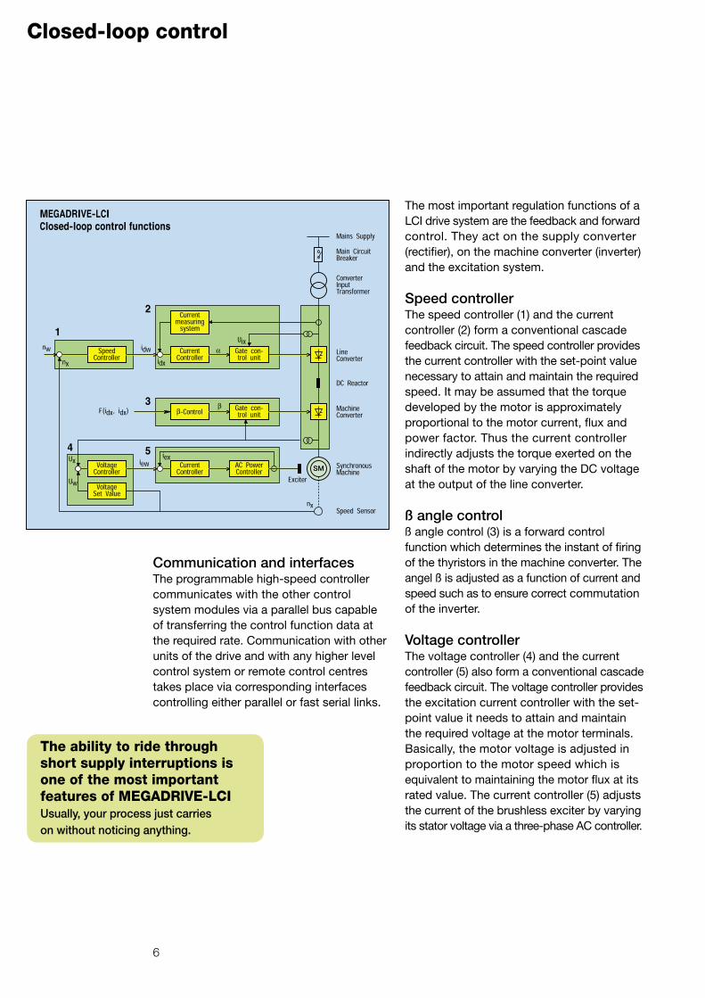
Closed-loop control
The most important regulation functions of a LCI drive system are the feedback and forward control. They act on the supply converter (rectifier), on the machine converter (inverter) and the excitation system.
Speed controller The speed controller (1) and the current controller (2) form a conventional cascade feedback circuit. The speed controller provides the current controller with the set-point value necessary to attain and maintain the required speed. It may be assumed that the torque developed by the motor is approximately proportional to the motor current, flux and power factor. Thus the current controller indirectly adjusts the torque exerted on the shaft of the motor by varying the DC voltage at the output of the line converter.
ß angle controlß angle control (3) is a forward control function which determines the instant of firing of the thyristors in the machine converter. The angel ß is adjusted as a function of current and speed such as to ensure correct commutation of the inverter.
Voltage controller The voltage controller (4) and the current controller (5) also form a conventional cascade feedback circuit. The voltage controller provides the excitation current controller with the set-point value it needs to attain and maintain the required voltage at the motor terminals. Basically, the motor voltage is adjusted in proportion to the motor speed which is equivalent to maintaining the motor flux at its rated value. The current controller (5) adjusts the current of the brushless exciter by varying its stator voltage via a three-phase AC controller.
Communication and interfacesThe programmable high-speed controller communicates with the other control system modules via a parallel bus capable of transferring the control function data at the required rate. Communication with other units of the drive and with any higher level control system or remote control centres takes place via corresponding interfaces controlling either parallel or fast serial links.
The ability to ride through short supply interruptions is one of the most important features of MEGADRIVE-LCIUsually, your process just carries on without noticing anything.

7
The protection and supervisory functions ensure that the mechanical and thermal operating limits of the drive are not exceeded. They are implemented in the application program running on the micro-processor of the programmable high-speed controller and their signals are evaluated by the diagnostic system. The most important protection functions (overcurrent and overspeed) are also duplicated by hard-wired devices acting as a back-up for the software protection functions. Trips and alarms are transmitted to the relevant devices to shut down or, should it become necessary, trip the drive completely. Faults are displayed in plain language on the control panel in the door of the control cubicle and on any remote control panel with clear indication of the first fault.Numerous protective and supervisory functions are available. The following are the minimum included with the standard MEGADRIVE-LCI.
Motor:Overvoltage, undervoltage, stalled rotor, winding and bearing temperatures, over-
Protection and diagnostics
speed and set speed deviation.
Converter:Supply over and undervoltage, overcurrent, ground fault, failure of auxiliaries, cooling water temperature, level, flow and conductivity, respec-tively air flow in the case of air-cooled units, and excitation and control system failure.
Supply transformer:Oil temperature and level and Buchholz in the case of oil-immersed types, respectively winding temperature in the case of dry types.
Also components are conservatively rated and more than adequate safety margins are allowed.Where appropriate, functions are physically isolated from each other in the interest of greater reliability.
A special design feature of MEGADRIVE-LCI is its ability to ride through brief supply interruptions so that in most cases they pass unnoticed by the process. Should the drive fail in spite of all these precautions, fault location and corrective action are made easy by the failure indication system which points to the precise component. Attention has also been paid to the simple replacement of all components,units and assemblies. For example, a thyristor can be replaced without having to interrupt the cooling water circuit. All the measures incorporated should achieve repair times of just minutes and an MTBF of more than 4 years.
Reliability is a must!Reliability and availability are of the utmost importance in power plants and industrial processes. As a leading supplier of drive systems, ABB achieves the highest reliability by ensuring that it complies with the quality standards and procedures specified in ISO 9001. Tests are performed at various stages during production in addition to the extensive final tests (heat run, combined, and burn-in tests are conducted on request). Redundancy of crucial components (e.g. cooling pump or fan and essential parts of the control system) can be provided which enormously increases reliability and availability while enabling maintenance intervals to be extended to 4 years and more.

Applications
8
Compressor hallwith 3 reciprocating compressors equipped with MEGADRIVE-LCI in a natural gas pumping station
Boiler feed pumpsin a thermal power plant driven by MEGADRIVE-LCI
Continuous rating : 10 MW, 500 … 5222 rpm
Short-time rating: 13 MW, 5700 rpm
Shaft output per drive: 4.7 MW
Speed range: 0 … 375 rpm

Applications
Wire block drivewith MEGADRIVE-LCI
9
Polyethylene extruder drivewith MEGADRIVE-LCI
Continuous rating : 5.5 MW
Torque: 44.3 kNm
Speed range: 120 … 1185 rpm
Continuous rating: 5 MW
Speed range: 900 … 1500 rpm

Converter design and cooling
10
Part of a water-cooled thyristor stack
Compact and modularThe main components of a converter are:
• thyristor stacks with thyristor heat sinks • snubber circuits• gate control units with either magnetic or
optical fibre transmis-sion of the control impulses• semiconductor supervision devices• reactors• current and voltage transformers• fans in the case of air cooling• cooling unit with heat exchanger and pumps in the case of water cooling• control and protection equipment• excitation system
• local control panel
Both the power and control sections of the converter are constructed as modular units. For powers up to 22 MW, all the modules are mounted on a common base frame and fully
metal clad and are shipped as a single unit.Converters for higher ratings are broken down into suitable units for shipment.
The standard DIN enclosure protection class is IP30 for water-cooled converters and for air-cooled converters.Special enclosures and proofing are available to comply with higher protection classes.
The advantages of modular construction are:
• compactness and robustness• fast erection on site• adaptability to the customer’s needs• ease of maintenance• simple replacement of components• easy to handle and ship
High voltage for high powerAt the lower end of the power range, a single thyristor per branch is usually sufficient. Higher powers are generally achieved by connecting thyristors in series to divide the voltage rather than in parallel to share the current. The series connection of thyristors or thyristor bridges (e.g. for 12-pulse operation) has thus become standard practice for converters with voltage ratings up to 7 kV.Special designs are available up to 20 kV.
A high basic insulation level inside the cubicles minimises the risk of short-circuits.
The advantages of a high system voltage are:
• reduced losses because the higher power is achieved with less current
• better cost/benefit ratio for the motor• cheaper cables with lower cable losses• fuses can be avoided.
Water-cooled MEGADRIVE-LCIRated power: 5 MW

Efficient cooling means higher reliability
Air-cooling• Open-circuit:
Fans force the cooling air through the thyristor heat sinks.
This method is suitable in plants with clean air conditions.
• Closed-circuit:The cooling air circulates in a closed circuit inside the converter cubicles. The air in the closed cooling circuit is cooled by an air-to-air or air-to-water heat exchanger.This method is necessary in plants with dusty and/or aggressive atmospheres.
The advantages of air cooling are:
• simplicity• overload capability for short duty cycles• permits converters to be installed where
cooling water is not available.
Water-coolingDeionised water flows in a closed-circuit through the thyristor heat sinks and around the snubber circuit resistors and is cooled by either a water-to-water or water-to-air heat exchanger. This method is necessary for high-power applications and in plants with dusty and/or aggressive atmospheres. Circulation pump, monitoring devices for flow, temperature and conductivity are part of the converter assembly. No cooling water pipes have to be disconnected or drained in order to replace a thyristor.
The advantages of water cooling are:
• space-saving layout• losses easily conveyed from control room• higher ambient temperature permissible• less noise• fully enclosed cubicle with protection
class up to IP55 (protection against dust and splash water) for noise reduction and severe ambient conditions available
Air-cooled MEGADRIVE-LCI driving a boiler feed pump in a nuclear power plant
Rated power: 3.4 MW
Operating mode: 12/12-pulse
11
Walk-in enclosureFor outdoor erection, the converter complete with auxiliaries, switchgear, reactors and air-conditioning plant can be installed in a fully sealed enclosure which can be supplied for varying severities of ambient conditions. All components are wired and the system tested at the works prior to delivery which considerably reduces the time required for erection and commissioning on site.
Water-cooled MEGADRIVE-LCI driving a natural gas compressor
Rated power: 41 MW
Operating mode: 12/12-pulse
Walk-in outdoor enclosurefor two MEGADRIVE – LCI’s driving boiler feed pumps in a power plant

High-speed synchronous motor drives
The maximum possible speed of a directly connected two-pole synchronous motor on a 50 or 60 Hz system is 3000, respectively 3600 rpm.Higher speeds can be obtained from a two-pole motor by inserting a frequency converter in the motor supply which applies frequencies higher than the power system frequency to it. The maximum speed possible for a synchronous motor in this kind of arrangement varies with power rating, but cannot exceed about 7500 rpm due to the constraints of the rotor and exciter design (see diagram on page 4).
High-speed synchronous motor driving a boiler feed pump in a power plant
Continuous rating: 10 MW
Speed range: 500 … 5222 rpm
Short-time rating: 13 MW at 5700 rpm
12
High-speed drive referencesSince the first high-speed synchronous motors with LCI frequency converters went into service at the beginning of the 80’s, ABB has installed more than 60 with a total power of about 700 MW. They are used mainly for driving boiler feed pumps in power plants and large compressors in gas and chemicals and in various kinds of test bays. The individual power ratings range from 2.5 MW up to41.5 MW and they operate at speeds up to 6500 rpm. Drives for applications in hazardous areas have been constructed to meet the corresponding standards and have been certified by authorities following extensive testing at the works. In all cases, the performance of these high-speed drives has been excellent and they are operating to the full satisfaction of the users.
Proven converter designThe LCI converter used to supply a variable voltage and frequency to a high-speed synchronous motor is basically the same as those already described for operation at normal speeds. The only difference is the higher output frequency which can be as high as 125 Hz. Both supply and machine converters usually operate in a 12-pulse mode and most are equipped with water-cooled thyristors.
High-speed drive applications• compressors for drives in gas and
chemicals• boiler feed pumps in power plants• drives for test bays
Advantages• no gears and therefore higher reliability
and availability• reduced length of shaft train• much improved drive efficiency• low maintenance costs

Motor design
Extreme left: high-speed EEx «p» synchronous motor designed for driving a five-stage compressor in a chemical plant producing ethylene
Rated power: 13 MW
Speed range: 5700 … 6400 rpm
In general, the mechanical and electrical design of a high-speed synchronous motor corresponds to that of a standard ABB air-cooled turboalternator slightly modified for supply by a converter.Established methods and the experience gained over many years can thus be directly applied. There are two sets of stator windings shifted by 30° to eliminate the 6th and the 18th torque harmonics. The cylindrical rotor is a forged monoblock in which equally spaced slots for the rotor coils are machined around the circumference. The electrically conducting slot wedges and the interconnecting retaining rings form the damper winding. The retaining rings are made of a high tensile strength non-magnetic steel alloy and oppose the centrifugal forces acting on the rotor end coils. The exciter rotor and the diode wheel are shrunk onto the end of the shaft projecting from the motor bearing and are supported by a third bearing. This ensures that a critical whirling speed cannot occur within the normal operating speed range. Two axial flow fans provide self-ventilation and the air is cooled by an air-to-water heat exchanger.
13
Rotor of a high-speed synchronous motor with the exciter and rotating diodes on the left
High-speed synchronous motor
Rated power: 10 MWRated speed: 6000 rpm

MEGADRIVE-LCI.ST Starter for synchronous machines
14
Main features• starting current limited to the rated
machine current or less• provides facility for braking the machine• sequential starting of several machines
possible with a single soft starter• microprocessor control system
OperationThe synchronous machine is started with a variable frequency by the converter in the same way as a converter-fed variable speed motor (see MEGADRIVE - LCI). At rated speed, the machine is automatically synchronised to the power system and the circuit-breaker for direct connection to the supply is closed. The motor is excited from standstill.
Typical applicationsStarting of• gas turbines• synchronous compensators• refiner motors• motor/generators in pump storage
power plants• large compressors and blowers for: chemical processes
wind tunnelsblast furnaces
ReferencesWorld-wide, ABB has installed more than 360 solid-state converters as starters with ratings between 1 MW and 60 MW. These are in use in a variety of applications and the technique has proved highly reliable for over 20 years.
Starting a large synchronous machine on-line can prove problematical either because of the inrush current or because of the thermal stress at hot spots on the rotor surface while running up. These problems can be overcome with the aid of solid-state «soft» starting equipment which for this reason is being used in an increasing number of applications. Technical data
Typical power range: 2 … 80 MWMaximum speed: 3600 rpm (+5 %)Output frequency: 0…60 Hz (+5 %)
Gas turbine starting converter Type LCI.ST 3.8
Rated power: 3.8 MW

MEGADRIVE-LCI.ST
15
Features and optionsThe converter circuit is chosen to suit the particular application and requirements.
• 12-pulse supply and machine converters minimise distortion of the supply voltage and heating losses in the rotor due to harmonics
• matching transformer at the converter output
• changeover switchgear
Optional redundant components:
• (n+1) thyristors per arm of a thyristor bridge
• separate exciter converter for starting• Cooling ancillaries:
Air-cooling: redundant fansWater cooling: redundant pump Left: Solid-state starter with
12-pulse converters and matching transformer at the output
Right: Solid-state starter with 6-pulse converters for the rated motor voltage
MEGADRIVE-LCI.STSolid-state frequency converter for starting motor/generator sets in pump storage power plants
Rated power: 24 MW
16
Engineering a MEGADRIVE-LCI-system
• reliability and availability• control• overall efficiency• total cost
An optimum drive system can only be achieved if there is close cooperation between the machine and converter design engineers and this is given top priority at ABB. The motor design must take due account of the losses resulting from the harmonic content in current and voltage and the pulsating torque. The torsional forces exerted on the shaft train are analysed by computer to ensure proper mechanical performance.
It is not sufficient to just consider the motor and the converter when deciding on a suitable voltage level. Overall efficiency, the switchgear and other characteristics of the specific plant have to be included as well. An understanding of the user’s application, national standards and the prevailing ambient conditions on site is also essential to engineer a fully satisfying drive system.
A MEGADRIVEsystem – thetotal solution
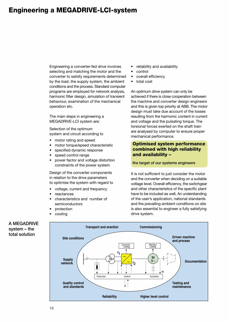
Engineering a converter-fed drive involves selecting and matching the motor and the converter to satisfy requirements determined by the load, the supply system, the ambient conditions and the process. Standard computer programs are employed for network analysis, harmonic filter design, simulation of transient behaviour, examination of the mechanical operation etc.
The main steps in engineering a MEGADRIVE-LCI system are:
Selection of the optimum system and circuit according to
• motor rating and speed• motor torque/speed characteristic• specified dynamic response• speed control range• power factor and voltage distortion
constraints of the power system
Design of the converter components in relation to the drive parameters to optimise the system with regard to
• voltage, current and frequency• reactances• characteristics and number of
semiconductors• protection• cooling
Optimised system performance combined with high reliability and availability –
the target of our systems engineers

17
Standard converter types Motor design criteria
Standard versions 1)
Smallest size Largest size2)
Air-cooled Water-cooled Air-cooled Water-cooled Type designation E0806-211N4 W1212-091N4 A1212-171N4 W2 x 06-573N4 Input voltage [V] 2100 2 x 940 2x1750 2 x 5710 No. of thyristors in series 1 1 1 3 AC current [A] 775 1880 1410 1610 Frequency (up to) [Hz] 60 60 60 60 Motor power [kW] 2100 4660 6330 23520
Design criteria for large converter-fed AC motorsIn order to guarantee the specified output and reliable operation of a large adjustable speed AC motor designed for supply by a converter, ABB pays special attention to the following:
• The motor cooling system remains fully effective throughout the specified range of speeds at the specified load.
• Full account is taken of the additional losses resulting from the harmonic content in voltage and current.
• The motor insulation is suitable to with-stand the voltage waveforms including surges and du/dt phenomena which may occur in practice.
• Motor and converter voltages are chosen such that overall drive efficiency and cable costs are an optimum.
• The motor reactances are matched to converter operation.
Synchronous motor 9 MW, 1500 rpm
• Where any doubt exists, a torsional analysis of the shaft train is recommended.
• The excitation system is designed to excite the machine at any speed and at standstill.
• Noise levels which are not necessarily the same as an equivalent conventional AC motor are checked in relation to the customer’s specification.
• The motor protection and supervision functions are suitable for converter operation.
1) Data for specified conditions regarding
• power supply
• cooling
• overload
• without redundancy
• suitable voltage and commutation reactance of the
motor
2) Higher power ratings on request

18
MEGADRIVE-LCI under test
Routine testing of a frequency converter.
Back-to-back testing of two high-speed (6000 rpm) 10 MW MEGADRIVE-LCI drives at ABB’s motor works at Birr in Switzerland. The associated converter cubicles and supply transformers can be seen behind the two motors.
Combined testsFor newly developed systems or at the customer's request, the frequency converter is tested in combination with a motor at the works to verify its performance and that it conforms to the design data.
Large units are tested «back-to-back» (see picture above), i.e. one converter/motor combination drives a similar combination in a generation mode. ABB has adequate facilities to perform all these tests.
Load testsMajor components, sub-systems or the complete drive are tested on load to verify power or current output at rated and overload operating points under defined cooling conditions. If desired these tests can also verify the
efficiency of the item concerned (segregated loss method).
Special and performance testsAt the customer’s request, special tests on the complete drive system can be carried out to check the noise level, short-circuit capability, electromagnetic compatibility (EMC) etc.
Routine testsEvery component or sub-system of a drive is tested as part of the normal production process. They are carried out in accordance with international standards (e.g. IEC) and ABB quality assurance procedures (ISO 9001).
Every component of a drive is subjected to thorough testing to verify that quality standards and customer requirements are fully met. Routine tests and functional tests form an integral part of the scope of supply of a MEGADRIVE system. Where additional tests such as load tests, combined tests or special tests are considered necessary, they should be agreed as early as possible.
19
At your service…ABB after-sales
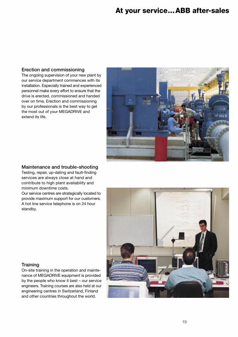
Erection and commissioningThe ongoing supervision of your new plant by our service department commences with its installation. Especially trained and experienced personnel make every effort to ensure that the drive is erected, commissioned and handed over on time. Erection and commissioning by our professionals is the best way to get the most out of your MEGADRIVE and extend its life.
Maintenance and trouble-shootingTesting, repair, up-dating and fault-finding services are always close at hand and contribute to high plant availability and minimum downtime costs. Our service centres are strategically located to provide maximum support for our customers. A hot line service telephone is on 24 hour standby.
TrainingOn-site training in the operation and mainte-nance of MEGADRIVE equipment is provided by the people who know it best – our service engineers. Training courses are also held at our engineering centres in Switzerland, Finland and other countries throughout the world.

ABB Switzerland LtdMedium Voltage DrivesCH-5300 Turgi / Switzerland
Tel +41 (0)58 589 27 95Fax +41 (0)58 589 29 84Email [email protected] www.abb.com/motors&drives
MEGADRIVE-LCI – Scope of Supply
Request information on other adjustable speed drives and further information on the MEGADRIVE series from your local ABB company or agent.
• Erection assistance *
• Commissioning *
• Mechanical analysis of the shaft train *
• Combined/load testing *
• Personnel training *
• Computer simulations *
• Maintenance contract *
• Motor with exciter
• Frequency converter
• Control, protection and supervision systems
• Supply transformer and reactors
• Cables *
• Harmonic filters *
• Power factor correction devices *
* optional
3B H
T 49
0 11
2 R
0001
Prin
ted
in S
witz
erla
nd (
1203
-100
0-0)