lc)i - defense technical information · pdf filelc)i f1. vcte mar 141~991 d japzowed ......
TRANSCRIPT

LC)I
F1. VCTEMAR 141~991
D
jApzowed toi 0= rpoes"
91 3 08 3
THE UNITED STATES NATIONAL
TECHNICAL INFORMATION SERVICE
IS AUTHORISED TO
REPRODUCE AND SELL THIS REPORT
Analytical Calculations ofFatigue Loading of Submarine Hulls
LM. Robertson
MRL Technical ReportMRL-TR-90-26
Abstract
Fatigue is a potential failure mode of submarine pressvre hulls. Australia's new Type 471submarines will be constructed from a new high strength steel. The higher design loadingsmade possible by the higher strength make fatigue an even more significant consideration
than in other designs. The stress analysis of submarine pressure hulls under hydrostaticloading is reviewed. The main emphasis is on analytical methods of calculation as opposedto numerical (e.g. finite element) methods, and on the calculation of the fatigue loadingrather than the calculation of buckling pressure. Because of the emphasis on fatigue, stress
concentrations, residual stresses and the interaction between residual and applied stressesare considered.
Accesion ForNTIS c[pA&Il( Dnic IA3
R Avail an,: ur
MATERIALS RESEARCH LABORATORY

Published by
DSTO Materials Research Laboratory
Cordite Avenue, MaribyrnongVictoria 3032, Australia
Telephone: (03) 319 3887Fax: (03) 318 4536
© Commonwealth of Australia 1990AR No. 006-326
APPROVED FOR PUBLIC RELEASE

Author
Ian Robertson
Dr Ian Robertson graduated BMet (Hons) from theUniversity of Newcastle in 1979, and was awarded a PhD in
Metallurgical Engineering from the University of Illinois in
1983. ie joined MRL in 1988, where his main interestshave been magnetic properties offerromagnetic materials,' and fatigue of welded structures. le has broad experiencein ferrous and non-ferrous metallurgy, and moderntechniques for materials characterization.
Contents
1. INTRODUCTION 7
2. CURRENT RELEVANCE 11
3. SIMPLE STRUCTURES 11
4. YIELDING, BUCKLING AND SUBMARINE DESIGN 12
5. ELASTIC STRESS ANALYSIS OF SUBMARINE HULLS 175.1 Introduction 175.2 Illustrative Example 175.3 Symbols 205.4 Uniformly Framed Cylinders 225.5 Computer Program for Uniformly Framed Cylinders 235.6 Stress Concentrations due to Axisymmetric Structure 23
5.6.1 Cylinder-Hemisphere Junction 265.6.2 Flat Plate End Closure 325.6.3 Bulkhead or Heavy Stiffening Ring 375.6.4 Other Junctions 38
5.7 Non-Uniform Framing and More Complex Geometries 415.8 Hull Attachments and Penetrations 42
5.8.1 Holes in Plates and Cylindrical Shells 455.8.2 Local Loads Applied to Cylindrical Shells 48
5.9 Residual Stresses 495.9.1 Residual Stresses due to Cold Bending of Plates 49
5.9.2 Residual Stresses due to Welding 525.10 Shape Imperfections 555.11 Stress Concentrations 56
6. FATIGUE 57
7. CONCLUSION 58
8. REFERENCES 59
APPENDIX I - Von Sanden and Gunther (IgnoringEnd Pressure) 65
APPENDIX 2 - Von Sanden and Gunther (IncludingEnd Pressure) 67

APPENDIX 3 - Viterbo 68
APPENDIX 4 - Salerno and Pulos 69
APPENDIX 5 - Wilson's Asymptotic Method 71
APPENDIX 6 - Wilson's Fourier Series Method 73
APPENDIX 7 - Stress Concentration due to Bulkheador Heavy Frame 74
Analytical Calculation ofFatigue Loading of Submarine Hulls
1. Introduction
The following introductory remarks are based on reviews of the subject by Wenk (1961),Kendrick (1985) and Bushnell (1985). Submarine pressure hulls are the world's largestpressure vessels. The major design loading is the external hydrostatic pressure at depth, but asubmarine hull is also subject to hydrodynamic stresses, and possibly to stresses arising fromenemy attack. The stress analysis of the hulls is a well-developed science because it isimportant to produce a hull of minimum weight in order to retain sufficient buoyancy forpropulsion systems, weapons and sensors. Accurate stress analysis results in precisiondesign and the confidcnt use of safety factors of the order of 1.5 or less. Accuracy in strengthprediction has been confirmed by tests to destruction of small and large scale models, and bystrain gauging of submarines.
A submarine pressure hull typically consists of a cylindrical centre section closed at theends with spherical or torispherical caps. Some examples are shown in Figure 1. The capsare usually convex, but may be concave (as viewed from outside the submarine) or even flatas in many Kockums designs. The cross section may be tapered towards the ends by theinsertion of conical sections. More general shapes are also possible, including figure-of-eightor even triple-hulled cross sections, or more fish-shaped single hull configurations. A recentItalian design consists of numerous toroids welded together (Compton-Hall, 1989).
The challenge for stress analysts is to calculate the extent of stress concentiation attransitions (e.g. between the end caps and remainder of the hull, cone-cylinder transitions), athull penetrations, and at other structural discontinuities such as bulkhead locations.

I S ,-
(a) German Type XXJ U-boat
(b) British Oberon class
(c) Frernch Daphnec lass
Fi~'urc 1: Examples of SISK submarine hull desig~ns (fromn Friedman, 1984; lanes. 1989)
8

(d) Cros-sections of Dutch Dolfljn class
77,4
(e) Swedish Sjoormcn class (Kockums design)
()Germnan Typc 209
Figure 1 (continued)
9

(g) Dutch Zwaardvis class
Moloc P Figur- 1 (c~ ontooinued)-rcop.Z
A IM0r-Ro
2. Current Relevance
This review is concerned with the stress analysis of Australia's new Type 471 sut-marines fortile purpose of assessing susceptibility to fatigue and corrosion fatigue. The pressure hull ofthe Type 471 is being constructed from a new, high strength, quenched-and-tempered steei.The susceptibility of steels to corrosion fatigut. generally increases as their strength increases,only partly because the higher strength allows design for higher stresses (de Hart, 1969:Thomson and Christopher, 1973). In addition, a submarine can expect a fatigue loading ofthe order of 104 cycles during its lifetime due to diving to depth. This puts it in the re,ime oflow cycle or medium cycle fatigue, where increased yield strength may decrease the S-Nfatigue life (Stout and Pense, 1965). Therefore the Type 471 is potentially much moresusceptible to fatigue and corrosion fatigue than the Oberon.
In this context, stress analysis is not required for calculation of collapse depth orbuckling mode. With the Type 471 design al-eady established, the requirement is forcalculation of stresses in the hull as a function of depth down to about two thirds of collapsedepth (assuming a safety factor of 1.5). WNthin this range an elastic stress analysis issufficient to obtain tle necessary data for fatigue and corrosion fatigue analysis. Thecombination of the expected mission profile and service life of the Type 471 submarinetogether with the elastic stress analysis, allows a fatigue loading spectrum to be predicted.
In this report the emphasis is on analytical solutions involving hand or simple computercalculations. This provides a qualitative picture of the overall behaviour and providescalibration points for more sophisticated computer stress analysis. Axisymmetric stressanalysis has become a routine process using codes such as ASSSAI and BOSOR4 (Robertsand Smith, 1988).
3. Simple Structures
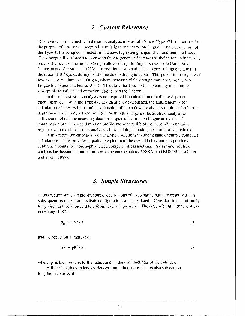
In this section some simple structures, idealisations of a submarine hull, are examniied. Insubsequent sections more realistic configurations are considered. Consider first an infinitelylong, circular tube subjected to uniform external pressure. The circumferential (hoop) stressis (Young, 1989):
c(T = -pR/h (1)
and the reduction in radius is:
AR = pR2 /Eh (2)
where p is the pressure, R the radius and h the wall thickness of the cylinder.A finite-length cylinder experiences similar hoop stress but is also subject to a
longitudinal stress of:
il

CV = G 0 /2 = -pR/2h (3)
due to pressure on the end closures. The basic stress state of a submarine hull is thicrefore
one of biaxial compression with the longitudinal stress half that in the circumferential
direction. Stress concentrations in a real hull c:.r, modify this significantly in local regions
and even result in regions of tensile stress.The reduction in radius for the finite length cylinder is:
AR = pR2 (I -v/2)/Eh (4)
Minimum-weight-design of a hull necessitates the use of a stiffened cylinder rather than a
simple shell. Because of the large circumferential stress component, the stiffeners are in theform of circumferential rings welded to either the inside or the outside of the hull plating.The stiffening rings (or "frames") usually have a T cross section. Under pressure the shelltends to bend inward between the stiffeners forming a concertina shape. Bending stresses areintroduced, and the stresses are no longer uniform through the thickness of the plating as theare in the case of a simple tube. The schematic geometry is shown in Figure 2.
4. Yielding, Buckling and Submarine Design
Failure of a pressure hull at great depth may be due to yielding of the hull steel, or due tosome form of buckling. The design determines which mode of failure actually takes place.The four primary modes of failure to be considered (Wenk, 1961; Kendrick, 1985) are:
(i) Yielding of the shell between the rings, characterised by an axi-symmetricconcenina-shaped pleat. This is also the elastic deformation mode prior to collapse.Yielding and other failure modes are illustrated in Figure 3.
ii) Inter-stiffener buckling ("local instability", "shell buckling") in which lobes developbetween the rings. The rings are at nodes of the buckling mode, and there is usually alarge number of lobes.
(iii) Stiffener tripping ("local stiffener instability") in which a ring fails by buckling.
(iv) General instability ("overall collapse") in which rings and shell tail simuhaneouslyfrom one end of the stiffened cylinder to the other, with two to five circumferentiallobes. In practice, general instability is probably precipitated by initial yielding or
stiffcner tripping.
12

Fiiure 2: Sche'natic diagramnshowing deflection of a rnl -stiffened cylinder under
hdostatic pressure tojorin a concertina shape.
Lobes Neat
BukIn YIedn
Overall~C_:: ntrsIne Stfee
loain. hor, ik olunsfal y yelin, sohulstht h shellsadclsl
spce sifcnrsOSver coun and-s hi shf wit wi e spaed Stifr fail by
bucklin~g. i he dimensions of the stiffeners determine whether shell buckling is local (heavy
13

stiffeners) or overall (light stiffeners), or whcthcr tripping occurs (very light stiffeners or
those with thin webs).To illustrate the general principles of buckling, consider a simple column. A
slender column under axial compression remains straight up to a critical load, Pcr' wherebuckling may occur. Below Pcr the column is in stable equilibrium. Above Pr twoequilibrium positions are possible (one straight, the other buckled). Even a smallperturbation can cause the transition from straight to buckled configuration. This is knownas bifurcation buckling.
For a pin-ended column the critical buckling load is (Popov, 1978):
Pcr = t EIx / L2 (5)
where E is Young's modulus, Ix is the moment of inertia and L the length of the column.The corresponding critical compressive stress in the column is:
acr = Pcr / A = it 2E/x 2 (6)
where A is cross section and X the slenderness ratio, I / L2A.
Above the critical load or stress, the buckled mode
w = w, sin (rtz/L) (7)
becomes possible in addition to the straight column (axisymmetric) mode w = 0, where w isthe sideways deflection and z the coordinate in the axial direction.
If 0 cr exceeds the yield stress of the material, oy , then yielding occurs rather thanbuckling. As yielding occurs and work hardening begins, the effective stiffness is the tangentmodulus Et rather than the elastic modulus E. Therefore bifurcation buckling may occur atthe point of yielding or after some plastic deformation. These ideas are summarised inFigure 4 (from Wenk, 1961). Parameters analogous to acr and X for stiffened cylindricalshells are identified and test results compared with equations analogous to equation (6).
True bifurcation buckling occurs only in unrealistic, ideal situations where the bucklingdeformation mode is orthogonal to the elastic deflection mode (i.e. buckling mode amplitudeequals zero regardless of the extent of elastic deflection; Bushnell, 1985). In practice,geometrical imperfections and/or loading eccentricity are present, so that the buckling modedevelops continuously from the initial irregularities as load is increased. Non-linear,elastic-plastic collapse (under rising load) or geometrical "snap-through" (under falling load)are the only buckling modes observed. Increasing eccentricity or initial imperfectionamplitude decreases the buckling load as shown in Figure 5.
14

YietdingPlastic Instability
Elastic Instability
U
II .•1 /X
Slenderness X=: 2RLfIh 5//E
Figure 4: Experimental data points showing the effect of slenderness ratio , on the failure
mnode and collapse pressure Pc for ring-stiffened cylinders. Elastic buckling occurs for
X > 1.2 (from Wenk, 1961).
is

(a) Radial tieletin of tn itnperject cylinder on increasing pressure Jtoif 0 to SO1 psi.
Ordinary Buckling Snap ThroughBuckling
e 0 Euter 31,V L).d
e0-
Throu~
Displacement Displacement
(b) Schematic load-displacement curves for ordinary buckling (column) and snap through(spherical shell).
Figqure.5: Efltce of geomnetrical itrnperjections (or eccentricitv e) on the lbuckling oJcylinder, colunin and sphere (ftoin Wenk, /96/).
16

The calculation of the critical pressure (or collapse depth) is a primary concern during
the design of a submarine hull. The usual approach is to consider each possible failure modeseparately. It is possible to predict p,, more accurately for some modes than for others, sodifferent safety factors are applied for the different modes (for example, overall collapse ismore sensitive to imperfections than other modes). The usual procedure (Kendrick, 1985) isto proportion the shell plating thickness and stiffener dimensions so that collapse at pressures
in excess of the design pressure would occur by inter-stiffener collapse (with a safety factor of1.5). Premature failure by overall collapse or local stiffener instability are avoided by
applying safety factors of 2 and 4 respectively. Part of the reason for applying differentsafety factors is to avoid interaction between different failure modes.
In this report buckling is not a major concern. Rather the interest is in stress analysis atexternal pressures encountered in normal service, well below the critical buckling pressure.However, considerations of buckling largely determine the submarine design, and thereforeindirectly affect the stresses and fatigue loading encountered in normal service.
5. Elastic Stress Analysis of Submarine Hulls
5.1 Introduction
Much of the literature on the stress analysis of ring-stiffened cylinders, and other idealisationsof submarine pressure hulls, is concerned with the prediction of buckling pressure.. Thecalculation of elastic stresses in the hull is a much simpler task.
The early work was carried out by von Sanden and Gunther (1920) and von Mises (1929)in Germany at the time of World War I. This was extended after the war by variousresearchers at the David Taylor Model Basin, as reviewed by Wenk (1961). More recentreviews are those of Kendrick (1970, 1985) and Bushnell (1985).
Work prior to about 1955 emphasises analytical solution procedures and is restricted to
fairly simple (but not trivial) geometries. A wide variety of general and more specific
computer programs is now available for the stress analysis of structures including pressurevessels. The codes dealing with axisymmetric structures are most applicable to the stress
analysis of submarine hulls.
5.2 Illustrative Example
In order to gain a qualitative picture of hull stresses, consider the "typical" structure shown in
Figure 6. The stress distributions at various locations obtained using NCRE's PEGASUScomputer code (Kendrick, 1964) are shown in Figure 7. Away from stress concentrationsother than uniformly spaced stiffeners, the general features of the stress distribution in the
cylindrical sections are:
17

3AT 45 28 AT 45"
I" 53'
300 I.RAD. 1
M06 1. RA. 212" 1. DIA. 31e" 1. 0A. U"IRD
R=1064-2+ 53
450
II 13 15 40 42
Figuire 6: Example of a typical submarine pressure hull (Kendrick, 1964).
-100 Zvi OE
so - /5----0--
40 20 FR.I1. 20 FR.2. 20 FR. 3.DISTANCE ALONG GENERATOR -INS.
(a) Stresses near domne-cylinder junction
FigureT7 Stresses in the hull plating for the structure shown in Figure 6.
Longitudinal Outer surface- Inner surface
Circumferential---------- Outer surface-- - - Inner surface
18

200
5 6 7 8
F R. 5. 20 FR.6 20 F R.7. 20 \FR. 20 FR. 9.DISTANCE ALONG GENERATOR-INS.
(b) Stresses near cone-cylinder junction.
so 7YTL2 I..
_ /9
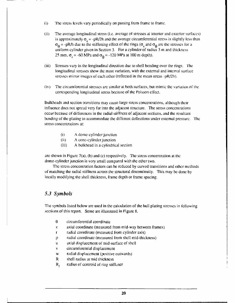
(i) The stress levels vary periodically on passing from frame to frame.
(ii) The average longitudinal stress (i.e. average of stresses at interior and exterior surfaces)is approximately oy = -pR/2h and the average circumferential stress is slightly less thanGo = -pR/h due to the stiffening effect of the rings (o, and o 0 are the stresses for auniform cylinder given in Section 3. For a cylinder of radius 3 m and thickness25 mm, o = -60 MPa and a 0 = -120 MPa at 100 m depth).
(iii) Stresses vary in the longitudinal direction due to shell bending over the rings. Thelongitudinal stresses show the most variation, with the external and internal surfacestresses mirror images of each other (reflected in the mean stress -pR/2h).
(iv) The circumferential stresses are similar at both surfaces, but mimic the variation of thecorresponding longitudinal stress because of the Poisson effect.
Bulkheads and section transitions may cause large stress concentrations, although theirinfluence does not spread very far into the adjacent structure. The stress concentrationsoccur because of differences in the radial stiffness of adjacent sections, and the resultantbending of the plating to accommodate the different deflections under external pressure. Thestress concentrations at:
(i) A dome-cylinder junction(ii) A cone-cylinder junction(iii) A bulkhead in a cylindrical section
are shown in Figure 7(a), (b) and (c) respectively. The stress concentration at thedome-cylinder junction is very small compared with the other two.
The stress concentration factors can be reduced by curved transitions and other methodsof matching the radial stiffness across the structural discontinuity. This may be done bylocally modifying the shell thickness, frame depth or frame spacing.
5.3 Symbols
The symbols listed below are used in the calculation of the hull plating stresses in followingsections of this report. Some are illustrated in Figure 8.
0 circumferential coordinatez axial coordinate (measured from mid-way between frames)r radial coordinate (measured from cylinder axis)p radial coordinate (measured from shell mid-thickness)u axial displacement of mid-surface of shellv circumferential displacementw radial displacement (positive outwards)R shell radius at mid thicknessR radius of centroid of ring stiffener
20

h shell thicknessLf ring stiffener spacingb ring faying flange widthL unsupported length of shell (L = Lf - b)Af cross sectional area of ring stiffenerp hydrostatic pressure (positive if external)E Young's modulus of shell and ringsV Poisson's ratio of shell and rings0 stressE strainM bending momentQ radial shear forceN membrane force (stress resultants)I h3 /[12 (1 -v 2)]D flexural rigidity of shell (D = El)If moment of inertia of ring stiffenerc fourth root of 3(1 - v2) / (hR)2
K frame rigidity constant (total load on ring per unit radial deflection perunit circumferential length)
LfL
w
R r0
Figure 8: Symbols used to describe the geometry of uniformly-framed, ring-stiffenedcylinders.
21
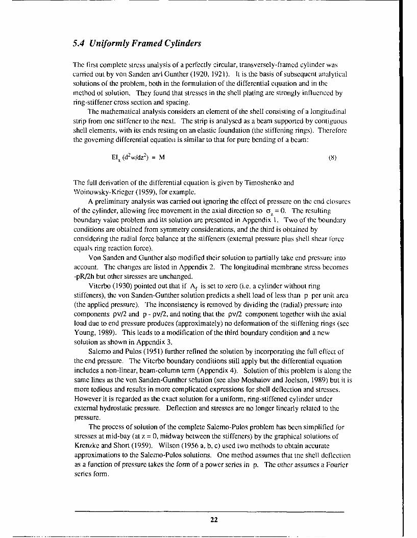
5.4 Uniformly Framed Cylinders
The first complete stress analysis of a perfectly circular, transversely-framed cylinder wascarried out by von Sanden anl Gunther (1920, 1921). It is the basis of subsequent analyticalsolutions of the problem, both in the formulation of the differential equation and in themethod of solution. They found that stresses in the shell plating are strongly influenced byring-stiffener cross section and spacing.
The mathematical analysis considers an element of the shell consisting of a longitudinalstrip from one stiffener to the next. The strip is analysed as a beam supported by contiguousshell elements, with its ends resting on an elastic foundation (the stiffening rings). Thereforethe governing differential equation is similar to that for pure bending of a beam:
Elx (d2w/dz2 ) = M (8)
The full derivation of the differential equation is given by Timoshenko andWoinowsky-Krieger (1959), for example.
A preliminary analysis was carried out ignoring the effect of pressure on the end closuresof the cylinder, allowing free movement in the axial direction so 0 z = 0. The resultingboundary value problem and its solution are presented in Appendix 1. Two of the boundaryconditions are obtained from symmetry considerations, and the third is obtained byconsidering the radial force balance at the stiffeners (external pressure plus shell shear forceequals ring reaction force).
Von Sanden and Gunther also modified their solution to partially take end pressure intoaccount. The changes are listed in Appendix 2. The longitudinal membrane stress becomes-pR/2h but other stresses are unchanged.
Viterbo (1930) pointed out that if Af is set to zero (i.e. a cylinder without ringstiffeners), the von Sanden-Gunther solution predicts a shell load of less than p per unit area(the applied pressure). The inconsistency is removed by dividing the (radial) pressure intocomponents pv/2 and p - pv/2, and noting that the pv/2 component together with the axialload due to end pressure produces (approximately) no deformation of the stiffening rings (seeYoung, 1989). This leads to a modification of the third boundary condition and a newsolution as shown in Appendix 3.
Salerno and Pulos (1951) further refined the solution by incorporating the full effect ofthe end pressure. The Viterbo boundary conditions still apply but the differential equationincludes a non-linear, beam-column term (Appendix 4). Solution of this problem is along thesame lines as the von Sanden-Gunther solution (see also Moshaiov and Joelson, 1989) but it ismore tedious and results in more complicated expressions for shell deflection and stresses.However it is regarded as the exact solution for a uniform, ring-stiffened cylinder underexternal hydrostatic pressure. Deflection and stresses are no longer linearly related to thepressure.
The process of solution of the complete Salerno-Pulos problem has been simplified forstresses at mid-bay (at z = 0, midway between the stiffeners) by the graphical solutions ofKrenzke and Short (1959). Wilson (1956 a, b, c) used two methods to obtain accurateapproximations to the Salerno-Pulos solutions. One method assumes that tne shell deflectionas a function of pressure takes the form of a power series in p. The other assumes a Fourierseries form.
22

The power series (asymptotic) solution is described in Appendix 5. For various testcases studied by Wilson, the asymptotic solution is within 5% of the Salerno-Pulos solution.It is regarded as satisfactory provided the linear term pw1 is much larger than the correctionterm p2w2 (where the total deflection is w = pw, + p2w2).
The Fourier series method (Appendix 6) allows another small refinement to thegoverning differential equation. In practice, only the first few terms in the Fourier series arerequired to obtain an accurate approximation to the full Salemo-Pulos solution. Wilson alsoused slightly modified expressions for the frame rigidity constant, K, and the shell stresses.The stress equations are based on simple elasticity equations for plane stress such as:
ax = E(c -vE )/(1-v 2) (9)
Wilson also considered the effects of factors such as out-of-circularity on shell stresses.These effects are considered in Section 5.10.
5.5 Computer Program for Uniformly Framed Cylinders
A computer program has been written at MRL to implement the:
(i) Von Sanden and Gunther(ii) Viterbo(iii) Wilson power series(iv) Wilson Fourier series
solutions for stresses in the shell of a uniformly framed cylinder subject to external pressure.Shell displacement and curvature, and longitudinal and circumferential stresses in the shell atmid-thickness and both surfaces are calculated (shell buckling is not considered).
5.6 Stress Concentrations due to Axisymmetric Structure
To this point only uniformly-framed cylinders have been analysed. In this section,consideration is given to some departures from uniform framing such as bulkheads, heavystiffeners, transitions (e.g. cylinder-cone junctions) and junction of a cylinder with endclosures.
The analysis is based on that presented by Gill (1970) for infinite cylinders subject toedge loading. For asymmetric loading of a shell element of length dz and width r dO thestress resultants are as shown in Figure 9 and the equilibrium equations are as follows:
23

r (a Nja z) + (a NOP 0) + rpz = 0
(a N0 0) + r(a N0/,3 z)- QO +rPO = 0
(a Q0/a 0) + r(a QJo z) + No - rp,=
Ol(10)
(a M0/10) +r(3Mzo/a z)- rQ 0 0
r(a Ma z) + (a Me,!a)-rQ,, = 0
rN, -rNoz +M 0 z = 0
8 +a dz dz
aUz
oz
Z"
N.99
d8
dz-d
Figure 9: Stress resultants for asymmetric loading of an element dz x r dO of a cylindricalshell.
24

If the loading is axially symmetric (e.g. hydrostatic pressure), p0 = 0 andN,0 = N0 z = M, 0 = Q0 = 0 so the equations reduce to:
(dNdz) + p, = 0
r (dQ,/dz) + NO - rpr = 0
(dM,/dz) - Q, = 0
For linear elastic material, and considering only shear (Q,) and moment (M) edge loading (at
z = const.), the following simplifications apply:
Pr = P, = ()Nz = ()
N/ 0
(12)No = Ehw/r
M/= D(d 2w/dz2)
Substituting into the equilibrium equations (11) gives:
El (d4 w/dz4)+Ehw/R 2 = 0 (13)
This is the differential equation for a circular cylinder subjected to rotationally symmetric
edge loading. It is equivalent to the initial Van Sanden and Gunther analysis with p = 0(Appendix 1). The general solution is as in Appendix I with p = 0, or equivalently, and more
conveniently in this case, is:
w = exp (az.) 1kI cos (az) + k, sin (az)l(14)
+ exp (-scz) [k3 cos (az) + k4 sin (z.)]
Consider a semi-infinite cylinder subjected to symmetric edge loadings M and Qat z = 0(Figure 10). Because the effect of the edge loading must decay with increasing z, the
coefficients k, and k, arc zero. The coefficients k3 and k4 are determined by the boundaryconditions at the free edge (z = 0).
Due to the exponcntial te-rm, the radial deflection w is significant only for aXz < 7E. For a5 m diameter steel pressure vessel with walls 25 mm thick, this condition is equivalk,..t to z <0.71 m (this distance is of the order of the spacing of submarine hull ring stiffeners). Thus the
effects of the edge loading are significant only in one bay.This is an important simplification in the analysis of hull stresses. A stress
concentration such as a bulkhead or heavy stiffener imposts radially symmetric loads on the
edge of the adjacent hull cylinder. The resulting deflections will usually only be significant
in the hull plating between the stress concentration and the nearest stiffening ring. Ilowever,
25

if two stress concentration points are located closer together than ir/ct, then the exp(az) termin equation (14) cannot be deleted and the interference between the two must be considered.
Q0 Deflected slape
Original undeflected
R wall of cylinder
t z
Figure 10: Edge loadings Q. and Mo on a cylindrical shell produce deflection w. and slopetan (0.) (from Gill, 1970).
Table 1 (Gill, 1970) shows solutions of equation (14) for various boundary conditions (edgeloadings). In the case of a submarine hull, the deflections due to hydrostatic pressure must beadded to obtain the complete solution. This process is described for various types of stressconcentrator in the following sections.
5.6.1 Cylinder-Hemisphere Junction
A well-studied situation giving rise to a stress concentration is the closure of a cylinder with ahemispherical cap. In the case of equal shell thicknesses, the stresses and radialdisplacements of simple cylindrical and spherical shells due to external pressure are:
26

Cl 0 0
0 ' C&I C4 0 J
0 0 0 0 0 0 0
0-. a) 0 o 0 0
-~ 3
3q 0~ 0' 2
0u 0
00
d~ '6 C
(.41
.10 x
I 27

Cylinder: ( 0 = -pR/h (1)
a,= -pR/2h (3)
W= - pR' (2- v) / 2Eh (4)
Sphere: 0= a V = -pR/2h (15)
81= - pR2 (1 - v) / 2Eh (16)
The deflections are not equal, so equal and opposite shear forces and bending moments mustexist at a junction between cylinder and hemisphere in order to maintain continuity. Theedge loading solutions for a cylinder shown in Table I and similar results for a sphere shownin Table 2 allow the shear force Qo and bending moment Mo to be obtained by equating thedisplacements wo and 80 and slopes dw/dz and tan(O) on either side of the junction. Theprocedure for calculating the total stress in the cylindrical and hemispherical shell involvessuperposition of the membrane and edge bending solutions, and is known as "discontinuityanalysis" (Cloud, 1970).
Gill (1970) gives details of the calculations. Referring to Figure 11 and Tables I and 2(noting 13 = t/2 in this case), the edge displacements and slopes due to edge forces Q. and M.are:
Cylinder: w( = 2Q. (.R2 / Eh + 2M. 0a2R2 / Eh (17)
00= -2Qo o2R2 /Eh - 4Mo 0 R2 / Eh (18)
Sphere: o = 2Mo ( 2R2 /Eh - 2Q. (xR2 /Eh (19)
00 = 4M o o3R 2 /Eh - 2Q. ox2R2 /Eh (20)
Matching the deflections and slopes across the discontinuity due to the combination ofhydrostatic pressure with the edge loadings therefore requires:
wl + w ° = 81 + ° (21)
00 = -2Qo ct2R2/Eh - 4M &3R2/Eh = 4M o &3R2/Eh - 2Qo c2R2/Eh(22)
These allow Mo and Q. to be obtained:
M= 0 (23)
Qo = P/ 8o (24)
28

Table 2 Edge Bending Solutions for a Spherical Shell (0 > 30')
Geometry
,-e ve6 +ve-
e1. M.4' M.
Stress Resultant
QOA exp(-c±RW~) sin(aRW4 + y) A exp (-otR,4) sin(oaRWi + y
No 0 ; '2(R A cxp(-aRW~) sin(oaRW~+y-n/1) + q2oLR A exp(-aLRW4) sin(aRy~y-n/4)
%A +(If'i2oz) A exp(-uLR0I) sin(ciRW~+y-ici/4) -(1/' 2a) A exp(-aRV) sin(aRWt+y+7/4)
Rotation
O (2a 2R2/Eh) A exp(-otRw~) cos(oLRxv+y) (2a 2R2IEh) A exp(-axRxI) cos(aRy+y)
Constants for Boundary Conditions*
.M.only A = 2ciM 0, Y=O A =-2oLMO Y=O
Q0 only A=rv2Q 0 sin13 y=-it/4 A=4 2Q~sin13 y=-nt/4
Edge Rotation
o0 (4a3R2/Eh)M 0 + (2a2 R2-hQ sin 13 -4( 3R2/Eh'M, - (aR/hQ i
Edge Deflection
SO (2a2RI/Fh)M 0 sin 13 + (2osR2 /Eh)Q 0 sin2 13 (2a2R/Eh)M 0 sin 13 + (2LR2 /Eh)Q, sin2 13
* The values of A and y are found for MO and Q0 applied separately and added beforesubstituting into the expressions for the stress resultants and rotation.
29

6, w,
R R
(a) '
80 Q.
(b)
Figure 11: Deflections and slopes at a hemisphere-cylinder junction (a) due to pressure and(b) due to edge loadings Qo and Mo.
The total deflections, due to Q0 (obtained from Tables 1 and 2) combined with those due to
hydrostatic pressure are:
w + wI = (pR2/4Eh) exp(-az) cos(ctz) - pR 2 (2-v) / 2Eh (25)
8 + 81 = -(pR 2/4Eh) exp(-RaWi) cos(Raty) cos(xy) - pR2 (l-v) / 2Eh (26)
Knowing the deflections, the stresses can now be calculated as in Appendices 1 to 6. Resultsare shown in Figure 12 (Gill, 1970). Note that the bending of the sphere and cylinder nearthe junction increases the longitudinal/meridional stress from -pR/2h to about -1.3 pR/2h atone surface (and reduces it to -0.7 pR/2h at the other). The hemisphere is stiffer than thecylinder in the radial direction, so the radial deflection of the cylinder is reduced at thejunction. This leads to reduced circumferential stress at that point for the cylinder (andincreased stress for the sphere). Bending has a relatively small effect on the circumferentialstress.
30

tres pRh 0.75
Meridional stress 0-25- Longitudinal stress
Sphere Cylinder
ot R* 31 01o 3 ot z
th tRCircumferential stress@*47R _
Sphere - -CylinderI I__ _I_ _I____ ___ ___
Figure 12: Stresses at the junction of hemispherical and cylindrical shells under externalhydrostatic pressure (from Gill, 1970. See also Figure 7).
--- - -------- Inner surface
Outer surface
31
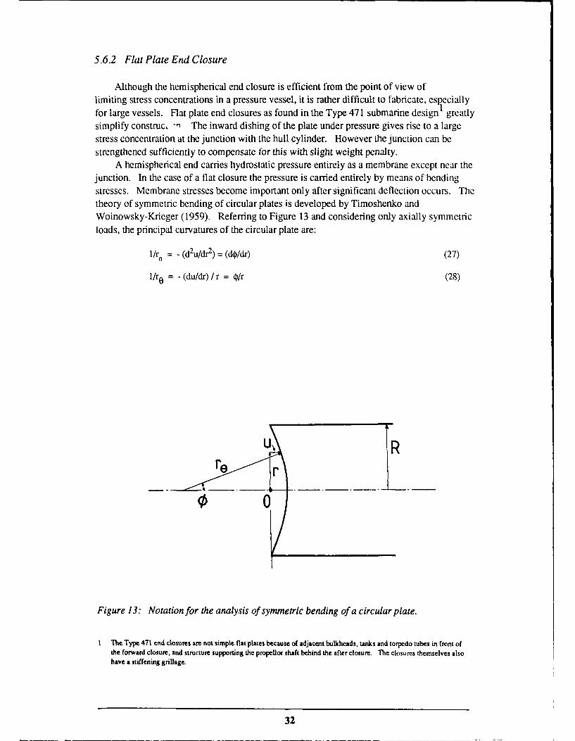
5.6.2 Flat Plate End Closure
Although the hemispherical end closure is efficient from the point of view oflimiting stress concentrations in a pressure vessel, it is rather difficult to fabricate, especiallyfor large vessels. Flat plate end closures as found in the Type 471 submarine design greatlysimplify construc - The inward dishing of the plate under pressure gives rise to a largestress concentration at the junction with the hull cylinder. However the junction can bestrengthened sufficiently to compensate for this with slight weight penalty.
A hemispherical end carries hydrostatic pressure entirely as a membrane except near thejunction. In the case of a flat closure the pressure is carried entirely by means of bendingstresses. Membrane stresses become important only after significant deflection occurs. Thetheory of symmetric bending of circular plates is developed by Timoshenko andWoinowsky-Krieger (1959). Referring to Figure 13 and considering only axially symmetricloads, the principal curvatures of the circular plate are:
l/r, = - (d u/dr 2) = (do/dr) (27)
1/r. = - (du/dr) / r = O/r (28)
0 0
Figure 13: Notation for the analysis of symmetric bending of a circular plate.
1 The Type 471 end closures are not simple flat plates because of adjacent bulkheads, tanks and torpedo tubes in front ofthe forward closure, and structure supporting the propellor shaft behind the after closure. The closures themselves alsohave a stiffening grillage.
32

The moments (per unit length in the plane of the plate) are:
M r = D (l/r n + v/r0) = D [(do/dr) + vo/r] (29)
M0 = D (v/r + 1/r0) = D [v (do/dr) + 0/r] (30)
Considering the torque on a small element of the plate about a tangential axis due to thesemoments and the axially symmetric shear force Q (per unit length), the equilibrium conditionis:
M r + (dM/dr)r - M 0 + Qr = 0 (31)
(d3u/dr3) + (d2u/dr 2) / r - (du/dr) / r2 = Q/D (32)
In the case of hydrostatic pressure loading, Q = pr/2 and the solution of the differentialequation is:
u = pr/64D + clr2/4 + c2 log(r) + c3 (33)
where the constants c1, c2 and c3 are determined by the boundary conditions. Taking u = 0at the circumference of the plate (r = R) and noting the symmetry requirement (du/dr) = 0 atr = 0 we have:
c2 = 0 (34)
c 3 = -(pR4 / 64D + ClR 2 / 4) (35)
u = p(r4 - R4) / 64D + cl(r 2 - R2 ) /4 (36)
For a plate loaded with pressure alone, Mr = 0 at r = R (free edge) and:
u = (p/64D) (R2 - r2) [R2 (5+v)/(l +v)-r 2] (37)
For a plate loaded with a radial edge bending moment Mr = M, (at r = R) in addition to thepressure:
u = (p/64D) (R2 -r2) [R (5 + v) / (I + v)- r21 + M0(R 2 - r2) / 2D(1 + v) (38)
The discontinuity stresses for a flat plate closure of a cylinder can now be calculated in thesame way as for a hemispherical cap by equating deflections and slopes across the junction.The forces required to maintain continuity are shown in Figure 14 (Cloud, 1970). Theresponse to pressure and edge moment have already been considered. The shear force F atthe edge of the plate is required to balance the pressure load (F = pR/2) and is independent ofthe deflection at the junction. For plates of practical proportions, the effect of the in-plane
33

force Q. can be neglected (the plate is effectively rigid and does not deflect radially, wp 0).However F and Q. must still be considered as far as the cylinder is concerned.
wQ 0 E
. F Mo i Pl
P
Figure 14: Discontinuity analysis of the junction between a cylindrical shell and a flat plate
end closure under external hydrostatic pressure. Forces F and Q., and moment M. act at the
junction.
Using equations (4), (17) and (18) for the slopes and deflections of the cylinder, and theresults above for the plate, the continuity conditions at the junction are:
wp = 0 = WO + w1 = 2QoOxR2/Eh + 2Moat2R2/Eh - pR 2(2 - v) / 2Eh (39)
(Note here that the term involving v takes the end force F on the cylinder into account.)
Op = (du/dr)r=_R = 0. = (dw/dz),,=0 (40)
pR3/8D (I + v) + MoR/D (I + v) = -2Qoa2R2/Eh - 4Mo a3R2/Eh (41)
34

Solving for M. and Q. assuming E and v are the same for the cylinder and the plate:
M ° - p [R3at3 H3 + (2 - v)(1 + v)] /4a 2 (1 + v + 2RaH 3) (42)
Q. p [R3CC3H
3 + 2 (2 - v)(l + v + RcxH 3)] / 4c(l + v + 2RcH 3) (43)
where H is the cylinder:plate thickness ratio (h/hp) and ax refers to cylinder dimensions.The deflections in the plate can now be obtained using equation (38), and the stresses arefound as follows (Timoshenko and Woinowsky-Krieger, 1959):
Cr = 12cMr / h3 = Ec[(d2 u/dr2) + v(du/dr) / r] (44)
( O = 12cM 0 / h3 Ec[v(d2u/dr 2) + (du/dr) / r] (45)
where c is the distance from the mid-thickness of the plate and ranges from -hp/2 to hr,/2.The cylinder deflections and stresses due to the edge forces Q0 and Mo combined with the
hydrostatic pressure are as shown below.
w = 2aR2 exp (-az) [Q0 cos(cxz) + aM° (cos ccz - sin (zx)] / Eh
- pR2 (2- v) / 2Eh (46)
d2w/dz 2 = 4a3 R2 exp (-axz) [Q0 sin(az) + aM0 (cos (z + sin axz)] / Eh (47)
z= - pR/2h - Ep [vw/R 2 + (d2w/dz2)] / (1 - v2) (48)
CF= Ew/R - vpR/2h - Ep [w/R 2 + V (d2w/dz2)] / (1 - v2) (49)
The deflections and stresses are illustrated in Figure 15. The flat plate closure causes a largestress concentration in the cylindrical shell adjacent to the junction because of the bendinginduced by the moment M.. A lighter end plate deflects more under pressure, imposes alarger Mo on the cylinder, and results in larger stresses in the cylinder. The stresses in the
end plate itself are small in comparison to those in the cylinder. A more detailed treatment ofthis problem is given by Watts and Lang (1982). Uddin (1987) considers the case of largedeformations. Harvey (1985) considers grillage and ring reinforcement of the flat plate.
From the point of view of fatigue, it can be seen that the flat plate closure not onlycauses a stress concentration. It also causes the stresses near the outer surface of thecylindrical shell to become tensile near the junction. In fatigue, only tensile stresses are
damaging (compressive applied stresses may also be damaging in the presence of tensileresidual stresses).
A simple flat plate end closure must be very thick compared with a hemispherical end
closure (or be reinforced). An alternative would be to thicken the cylindrical shell platingnear the junction, in order to reduce the bending stresses.
35

Stress x pR2z
hc
r0 0.5 \ 2 4+ 6 8 otz
O-z
r/o,
-2Plate -- Cylinder
(a) Circumferential (a) and radial/longitudinal (Y,/ a) stresses for plate thickness 500 mm.
Inner surface-------- Outer surface
0 2 4 6 8
R u
0.5
PR l' /-12)Ehc
0 r
(b) Deflections of cylinder (w) and plate (u).
plate 200 mm thickplate500 mm thick
Figure 15: Stresses and deflections for a cylindrical shell (radius 3 m, thickness 25 mm) withaflat plate end closure (thickness 200 mm or 500 mm) subjected to external hydrostaticpressure.
36

5.6.3 Bulkhead or Heavy Stiffening Ring
The stress concentration due to a bulkhead or heavy stiffening ring may also be obtained byapplying the edge loading formulas in Table 1. Considering an isolated stiffening ring in aninfinite cylindrical shell, symmetry requires 00 = 0 (Figure 10) at the location of the stiffener.This situation is covered by Case 3 in Table I (and also in Table 29 of Young, 1989).
The edge force, Q., of interest here is the difference between the reaction force of anormal stiffening ring, and the reaction force of the bulkhead or heavy stiffening ring. Thestress concentration due to the bulkhead or heavy stiffener can then be obtained bysuperposition with the solution for the uniformly framed cylinder.
The outward shear force per unit circumferential length, Q., applied to the hull plating bya standard stiffening ring is:
Q = - Kz=0 (50)
(The symbol o) refers to deflection of a cylinder without a bulkhead and the symbol w tothat of a cylinder with a bulkhead). In this case the coordinate origin has been shifted to thelocation of the stiffening ring to simplify the algebra (in Appendices I to 6 the stiffeners areat ± L/2). Thus 03z=O is the deflection at the stiffening ring (positive outwards). Thecorresponding force due to a bulkhead or heavy frame is:
Q1 = - KH ((0=0 + W.) (51)
where the symbols are defined as shown in Figure 16. wo is defined in this way to becompatible with Table 1. Quantities, w, co and wo are all positive in the outward direction, sow and (o are typically negative for external hydrostatic loading.
Cylinder Cylinder + Bulkhead
U.F.C. U.F.C. + Bulkhead
Figure 16: Deflections of a simple cylindrical shell and a uniformly framed cylinder with
and without a bulkhead.
37
The required ede force is therefore:Qo = Q-Q
= (K-K H) , - KI W (52)
From Table 1 we have another expression for Qo:
Q0 = Eh wo / R2c (53)
which allows the following solution for wo:
w° = (K - KH) 0=0 / (KH + Eh/R 2at) (54)
Again using Table 1 for the deflection of the stiffener due to the bulkhead or heavy stiffener,the total deflection is:
w = (j + R2ct (K- Ktl) O)= exp(-cwz) [cos(az) + sin(az)] / (R2aKit + Eh) (55)
where co is the deflection of the uniformly framed cylinder (or of the simple cylinder in thecase K = 0).
For the case of a perfectly rigid bulkhead (i.e. KH = 00, COz=O = 0 and w° = -(o) the hullplating displacement is:
w = c0- (0z= o exp(-az) [cos(czz) + sin(o.)] (56)
At the other extreme the bulkhead has the same stiffness as a normal stiffening ring (K,, = K)and w = co. Cases intermediate between these extremes are considered in Appendix 7.
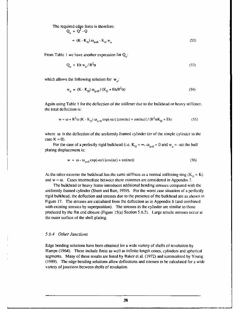
The bulkhead or heavy frame introduces additional bending stresses compared with theuniformly framed cylinder (Short and Bart, 1959). For the worst case situation of a perfectlyrigid bulkhead, the deflection and stresses due to the presence of the bulkhead are as shown inFigure 17. The stresses are calculated from the deflection as in Appendix 6 (and combinedwith existing stresses by superposition). The stresses in the cylinder are similar to thoseproduced by the flat end closure (Figure 15(a) Section 5.6.2). Large tensile stresses occur atthe outer surface of the shell plating.
5.6.4 Other Junctions
Edge bending solutions have been obtained for a wide variety of shells of revolution byHampe (1964). These include finite as well as infinite length cones, cylinders and sphericalsegments. Many of these results are listed by Baker et al. (1972) and summarized by Young(1989). The edge bending solutions allow deflections and stresses to be calculated for a widevariety of junctions between shells of revolution.
38

~pR (1-Y/2)
E h
1Stress 0(6 z
x pR 0"
h - 0"6
-2
Figure 17: Deflection and stresses for a cylindrical shell (radius 3 m, thickness 25 mm)adjacent to a rigid bulkhead.
Stresses at inner surface------ -Stresses at outer surface
See also Figures 7 and 15.
Only one further junction will be considered here; the junction between cylindrical shells ofunequal thickness. Proceeding as in Section 5.6.1, the deflection at the jur ztion (seeFigure 18) is.
wi + wo = 81 + 80 = w.- pR2 (2 - v) /2Eh 2
= 80 - pR2 (2 - v) /2Eh, (57)
0- 2R 21 2 M0 / EhI - 2R 2 tQ. / Eh, (58)
39

w ° =-2Rat 22M ° / Eh2 + 2R 2 t2Qo / Eh2 (59)
00 = -4R20al3 M,/Eh - 2R 2 a 12Qo /Eh I (60)
- 4R 22
3 M0 / Eh 2 - 2R2a2 2Q. / Eh 2
______44Oh, h2
R
Figure 18: Moment M. and shear force Q. required to maintain continuity of deflection andslope at the junction of two cylindrical shells of radius R.
Solving the pair of equations (57) and (60) gives:
p(h I - h2) (2- v) ( 12h2 -a2 2hl )
0 4(a 12h2 - 22h1) 2 - 8(ot23h, + al 3h2)(X1h2 + cz2hl)
Q0 = 2Mo (a 23 hI + a1
3h2) / (cX12h2 - C2 2hl)
(62)
Again following the same procedure as in Section 5.6.1, the deflections and stresses arecalculated from MO and Q.. Results for a particular case are shown in Figure 19. It shouldbe noted that shell theory does not take into account the stress concentration at the junctiondue to the geometrical change of section. Shell theory assumes uniform distribution of themembrane stress and linear variation of the bending stress through the thickness. The changeof section leads to non-uniform distribution near the junction (see Section 5.11).
40

DeflechondL Z Z cA i ) 2Z
pR 2(1-22)
hEh2
Stress
-6 -4 -2 2 4 6
-pR/2h,
-- - - -pR/2h2 - ' r' O'
. -pR/ h,
pR/h2"-
Figure 19: Deflections and stresses near the junction of cylindrical shells of thicknessh, = 50 mm and h2 = 35 mm (R = 5 m, v = 0.3) as calculated from shell theory.
Inner surface of shell-- Outer surface of shell
5.7 Non-Uniform Framing and More Complex Geometries
Analytical solutions for submarine hull stresses are effectively limited to the simple uniformlyframed cylinder (Section 5.4) and to relatively simple stress concentrators such as thoseconsidered in Section 5.6. Compared with the boundary value problem for theuniformly-framed cylinder, non-uniform framing adds to the number and complexity ofboundary conditions to be satisfied. Analysing cylinders of non-uniform thickness, cones,domes, toroids and combinations of these forms is more difficult again because the governingdifferential equations are also more complex.
41
Kendrick (1964) lists the differential equations for a general axisymmetric shell. Similarequations from Gill (1970) have been presented in Section 5.6 and other forms may be foundin the numerous textbooks on the subject (e.g. Gibson, 1980; Kraus, 1967; Timoshenko andWoinowsky-Krieger, 1959; FIigge, 1960; Baker et al., 1972; Novuzhilov, 1959). Whileanalytic solutions are available for special cases of interest (e.g. Young, 1989), computersolutions are much more general.
Axisymmetric stress analysis is much simpler than the general three dimensionalproblem, and computer codes have been written to capitalize on this simplicity. Theprograms available and their capabilities have been briefly reviewed by Bushnell (1974). Hissummary diagram is shown as Figure 20. A comprehensive review of the field is Bushnell(1985). In addition to static stress analysis, vibration and buckling of axisymmetric shells areencompassed by the programs. The effects of axisymmetric shape imperfections and residualstresses can also be investigated.
For dealing with parts of a submarine structure which are not axisymmetric, programsare available for general elastic-plastic shell analysis. Two of the better known ones areSTAGS (Almroth et al., 1980) and ASAS (Atkins, 1982). General purpose finite elementcodes such as NASTRAN and ABAQUS have also been applied to solving design problems.Brebbia (1985) has surveyed a large number of finite element and boundary elementpackages. Their capabilities are summarized in Figure 21. These programs requireconsiderable preparation and computing time. For this reason they are only applied to theanalysis of structural details after the overall structure has been considered using anaxisymmetric model.
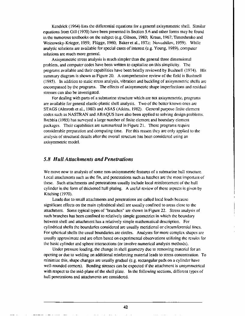
5.8 Hull Attachments and Penetrations
We move now to analysis of some non-axisymmetric features of a submarine hull structure.Local attachments such as the fin, and penetrations such as hatches are the most important ofthese. Such attachments and penetrations usually include local reinforcement of the hullcylinder in the form of thickened hull plating. A useful review of these aspects is given byKitching (1970).
Loads due to small attachments and penetrations are called local loads becausesignificant effects on the main cylindrical shell are usually confined to areas close to theattachment. Some typical types of "branches" are shown in Figure 22. Stress analysis ofsuch branches has been confined to relatively simple geometries in which the boundarybetween shell and attachment has a relatively simple mathematical description. Forcylindrical shells the boundaries considered are usually meridional or circumferential lines.For spherical shells the usual boundaries are circles. Analyses for more complex shapes areusually approximate and are often based on experimental observations utilizing the results forthe basic cylinder and sphere intersections (or involve numerical analysis methods).
Under pressure loading, the change in shell geometry due to removing material for anopening or due to welding on additional reinforcing material leads to stress concentration. Tominimize this, shape changes are usually gradual (e.g. rectangular pads on a cylinder havewell-rounded comers). Bending stresses can be expected if the attachment is unsymmetricalwith respect to the mid-plane of the shell plate. In the following sections, different types ofhull penetrations and attachments are considered.
42

a Ia -~o~Xa I
a~LA ~ I 0 -->aL, CIN
-~ LA 4 -OnZ - S C-a 4 - o-J a
4
I- -- -LA LA LA LA LAX a.~ aa a4LA O~ oa Oa
0 LA LA LA
LA a ~- ao a
4a~ CO~- >a
LA 0 -~ 0 04 4
-~ ~LA ~~LA ax-s a
cia OrCa On0
4LAX LAa~J
4 LAi.J
0
00 044,- OLAa LAWta mrOLA
mLA ~z444 a~ a~Z 2LAX LA~ LA-aC00 044
0 -~_____ _____ _____ C
Oi
aLA 04 -
Za-~.O a~aLA~ .. ic 0LA O,.aOar ~Z0~o 40LA LAXW&LAO aW4-a Ia LAa OO
44.~4 044~-4 LJ4
4 4,L~LAa4 W4LALALA LA~ LA
C
4- .,
0 a0 1
- LAa
4 >LAO-~ i.J04 -
ci0.
1~LA EO X 04 i- (.4
LA LA 4 ~ L.4 ~waLA 4
LA XLA LA
i-i CLA LA a I LA - t.)-4 a o~ LAaz OO~ ec't
- Ok) LAn-a4
LA0
o 1~.a LAX 044,- 0
LA-,
00 ~LALALA 4
-a
4 -~
aLA 0 LA0
LA4~4
Wi 4
- 0 t 4-
Jo -~ a£ 0-~ Li S * - * I-- *~0 Li -
- cE = EZ ~O C 0 C~5 '5- -ES~ - at S - - 0DLALA SLALA LALA p-LA LAta 1k) O.-L~ (N
~ - BJfl4)flJ4~ ~o A4ixi~dwoJ ~UiS28JJUI I..
43

Ln
. . .. . ..
C.
-o to
24
09 C
84 -o
. . . ._
~ 2C2 1220a 00
44

Figure 22: Typical types of shell branches.
5.8.1 Holes in Plates and Cylindrical Shells
Analytical solutions are available for the stress concentrations around holes in flat platesunder tension or bending, and also for simple cylindrical shells under external pressureloading. Peterson (1974) lists a variety of analytical and experimental results in graphicalform. Consider first the case of an elliptical hole in a thin, flat plate of infinite extent. Theclassic solution obtained by Inglis is described in some detail by Durelli (1981).
The uniform stresses 0 z and a are applied to an infinite sheet containing an ellipticalhole with semi-axes a and b as shown in Figure 23(a). The stresses at the edge of the holeobtained by Inglis are
CF = T=O
((z + y) sinh (2% ) + ( Fz- y)[cos(2) -exp(2a) cos 2(o- P)]- (=y+ ~ o [o(p (63)
cosh (2h) - cos (21)
where ct and P arc elliptical coordinates such that oX = a ° is constant at the edge of thehole so 0 a represents the stress perpendicular to the edge of the hole and a the stress tangentto the hole. At the ends of the major axis (for 0 = 0) z = a, y = 0, [ =0 and the tangentialstress is
45

al = cY (I + 2a/b)- a (64)
At the ends of the minor axis (0 = 0)
crp = cz (1 + 2b/a) - ay (65)
For the uniaxial stress case (az = 0) the stress concentration factor at the end of the major axisis
Kt = I + 2 a (66)
where p = b2/a is the radius of curvature at the end of the major axis.In the case of cylindrical bending (as opposed to biaxial loading above) with the
geometry shown in Figure 23(b), Savin (1961) provides the following solution. Themoments at the edge of the hole are
M =0r
My = M [1 + 2(1 + v)(1 - m)(m - cos 2y) / (3 + v)(m 2 - 2m cos 2y+ 1)] (67)
where r and y are polar coordinates and m = (a-b)/(a+b). The maximum moment occurs aty= ± r/2 and the minimum at yI = 0, it. The stress corresponding to the moment is
a = 12pM Y/h3 (68)
where p is the distance from the midplane of the plate in the thickness direction.The stress concentration factor for a circular hole in a cylindrical shell is higher than for
a hole in a flat plate. The Lurd solution described in Savin's (1961) compendium isapplicable to a hole in a capped, simple cylindrical shell subjected to pressure p, provided theradius of the hole r is small relative to the shell radius R and thickness h
r2 << Rh (69)
The hole is subjected to uniform biaxial stress (y = pR/2h and (Y = pR/h as described inSection 3. The tangential stress at the edge of the hole is
= (pR/h) (3/2 + cos(2y) + ntr2 -3(1 - v2) [4 + 5 cos(2y)] / 8Rh} (70)
where y is the polar angular coordinate (Figure 23b). The maximum stress occurs at y = 0.The stress concentration factor is
Kt = 5/2 +91rr 2 3(! -v2)/8Rh (71)
46

Ay
a.
y
M M
b
b.
Figure 23: Geometries of elliptical holes discussed in Section 5.8.1.
47

compared with 5/2 for a circular hole in a flat plate. For the particular case R = 3 m,h = 25 mm, r = 250 mm and v = 0.3, the SCF is 7.4 (this barely satisfies the conditionr2 << Rh). For r = 50 mm the SCF is 2.7.
Eringen et al. (1965) criticize the Lurd solution on the grounds of inappropriate boundaryconditions. They present results in graphical form for a thin, circular cylindrical, elastic shellwith a circular hole, subjected to various loadings. The effect of pressure acting as a shearloading on the edge of the hole is taken into account.
In the case of a submarine pressure hull, the stress around hull penetrations is reduced bythe addition of stiffening pads. The hull stiffening rings also reduce the circumferentialstress to below pR/h (also introduce bending moments) but are not expected to have a largeeffect on the stress concentration factor.
5.8.2 Local Loads Applied to Cylindrical Shells
Local loads have generally been considered in the form of line loads, area loads, or loadsapplied via nozzles or other local attachments. Summaries are given by Kitching (1970) andKraus (1967) for the case of local loading of cylindrical shells. Only geometrically simplecases are amenable to analytical calculations.
Hoff and co-workers (Hoff, 1954; Hoff et al. 1954) obtained analytical results formoments and radial loads applied along axial lines or circumferential arcs. Expressions forthe shell deflections u, v and w are obtained (containing eight arbitrary constants) whichautomatically satisfy the Donnell cylindrical shell equations. The expressions have the form
w = cos(nz/R){exp(-a1 0) [A, cos(3 10) + A2 sin(3 10)] + exp(-a 20)[A3 cos( 20) + A4 sin(J320)]
+ exp(al0)[A 5 cos(3 10) + A6 sin(010)] + exp(ct 20)[A7 cos( 20) + A8 sin(3 20)] } (72)
Since the deflection must decay with distance from the line load, only the negativeexponentials are retained. The four remaining constants Al to A4 are determined by theboundary conditions. The stresses and stress resultants are readily calculated once thedeflections are found. Different types of line load distributions can be handled using Fourierseries methods. The approach is analogous to that used to obtain edge loading solutions inSection 5.6.
Kitching also aummarizes the analysis of loads applied over rectangular areas of acylindrical shell. This can be done by direct integration of the effects of line loads, or can bedone more directly using Bijlaard's (1955a) procedure (see also Bijlaard, 1954, 1955b,1959a). The British Standard BS 1515 : Pt 1 : 1965 (as amended) Appendix A containsnumerous graphs allowing calculation of stresses in cylindrical and spherical shells adjacentto moments and radial loads applied to rectangular areas, axial lines and circumferential arcs.Some other relevant documents are Findlay and Timmins (1987) which gives a brief reviewof the development of the field, British Standard BS 5500 Appendix G, and Bedri et al.(1983). Tooth and Motashar (1989) consider the case of radial loading via a rigid rectangularattachment rather than the usual uniformly distributed loading. This method of loadingcauses stress concentration at the edges of the attachment.
The third major class of local loadings which have been studied consists of loadingsapplied over more circular areas of the cylinder surface. This type of loading is important in
48

the case of intersecting cylinders (such as pressure vessel nozzles, or hatches in submarinehulls). There is a large volume of literature. Graphical results for various types of loading
applicable to cylindrical nozzles in cylindrical pressure vessels are presented byMershon et al. (1984). Gill et al. (1970) give a brief overview of the theory for branches inspherical and cylindrical pressure vessels. Teixeira et al. (1981) present a simplified method
for calculating stresses due to loadings on branches in cylindrical vessels. Decock (1973)and Spence and Carlson (1967) consider fatigue assessment. Leckie and Penny (1963) andBijlaard (1959b) consider branches in spherical vessels.
Superposition of stresses due to external pressure and those due to branches is notconservative (it is for internal pressure). This difficulty can be overcome using anapproximate method described by Bijlaard (1955a).
5.9 Residual Stresses
The majority of fatigue and toughness problems associated with high strength steel submarinehulls are limited to welds and associated heat affected zones (Roberts and Smith, 1988). The
driving force for fatigue in these locations is the distribution of tensile residual/restraintstresses caused by welding (Kilpatrick, 1986) and the stress concentrating effect of the weldprofile itself. Without these stresses, the cyclic compressive stresses due to hydrostaticloading would be largely non-damaging. Another significant source of residual stress is theprocess of cold rolling the hull plate and stiffening rings to the required curvature. These
sources are considered in Sections 5.9.1 and 5.9.2 respectively.In addition to the fatigue problem, residual stresses are important from the point of view
of shell buckling. A brief review is given by Bushnell (1985, p. 192). Kendrick (1985)points out that residual stresses can have a large effect on collapse pressure if initial shapeimperfections are small, but have a lesser effect when the shape imperfections are greater (i.e.
the two effects are not additive).It is a relatively simple matter to calculate the residual stresses due to cold bending of
plate. Calculation of welding stresses is more difficult, but has been attempted for simple
geometries using a variety of numerical modelling techniques (see for example Masubuchi,1980; Jones et al., 1977; Bushnell, 1985). Only a simple analysis applicable to the fatigueproblem is attempted here.
5.9.1 Residual Stresses due to Cold Bending of Plates
Consider the simple case of an elastic-perfectly plastic plate which is initially bent to radiusof curvature R0 and then springs back to radius R. Assuming linear strain distributionthrough the thickness, the strain and stress when bent to radius Ro are
0 = p/Ro (73)
ao = 3Ep/Ro for p5 <aR 0 /EY ay for p > crR /E (74)
49

where p is the distance from the mid-plane of the plate, G3y is its yield stress and E itsYoung's modulus.
Ignoring Bauschinger effect and assuming elastic springback, the correspondingquantities when the plate returns to radius R are
C0 = p/R (75)
(O = Ep/R forp a R, /E (76)I y o
1 y -Ep (I/Ro - l/R) forp>oyRo/E
Equation (76) describes the residual stress distribution. It has a characteristic zig-zag shapeas shown in Figure 24.
z
---
h
Figure 24: Characteristic residual stress distribution through the thickness h of anelastic-plastic plate after cold bending to a curved shape.
50

The radius of curvature Ro which must be applied to the plate in order to achieve finalradius R can be found from the condition that the bending moment must be zero in the finalstate
M = 0 = 2 t Ep2/Rdp (77)
0
h/2
+ 2 J arp-Ep2 (l/R- I/R)dp
oyR/E
where h is the plate thickness. After a little algebra we obtain
R° = R (4- 3Q2 + Q3 ) /Q3 (78)
where Q is the parameter Eh/oyR o. The quantities defining the zig-zag residual stressdistribution (Figure 24) are
al/ay = RJR = (4- 3Q2 + Q3) / Q3 (79)
a2/ay = (4-Q2)/ 2Q2 (80)
z/h = 2/Q (81)
Kendrick (1970) shows values of these three quantities plotted against the parameter
F = Eh/ayR = RoQ/R = (4- 3Q2 + Q 3) / Q2 (82)
This is reproduced as Figure 25. In the case of submarine hulls, F has a typical value of 3,and the circumferential residual stress peaks due to cold bending are about half the yieldstress. The outer surface is in compression and the inner surface in tension.
More sophisticated calculations of the residual stress distribution have been made byincorporating various work hardening rules in place of the simple elastic-perfectly plasticmodel considered above (e.g. Shama, 1970). However, the elastic-plastic model is quitegood for submarine hull steels, and larger error is likely to accrue from lack of preciseknowledge of the yield strength of the particular plate than from neglect of work hardening(or the Bauschinger effect).
51

10
0 -8 0 1 /\-Y
08 \
0-6
0-40..
0.2 --'----- -
Z/h
0 I I
0 2 4 6 8Eh /Roy
Figure 25: Effect of the dimensionless parameter EhIRGY on the three parameters definingthe residual stress distribution (Figure 24) of a plate after cold bending to a curved shape.
5.9.2 Residual Stresses due to Welding
Welding residual stresses arise primarily from the shrinkage of the weld metal and HAZ oncooling from high temperature. The resulting stress levels depend heavily on the restraintimposed on this shrinkage by the remainder of the structure. For high strength steels typicalof those used to construct submarine hulls, a temperature change of 200-300 K is sufficientfor the shrinkage stress to reach the yield stress if thermal movement is fully restrained. Theresidual stress has short range and long range components due to non-uniform plastic strainsnear the weld and external restraint respectively (Lidbury, 1984). The short range stresses canbe considered to be confined to distances within a few plate thicknesses of the weld. Heavysection weldments are normally expected to have residual stress close to the yield stress in thelongitudinal direction throughout the fusion zone, and for a significant portion of the jointthickness in the transverse direction. The residual stress in the through thickness direction ismuch lower due to lack of restraint.
Short range residual stresses are difficult to treat analytically. However, the long rangerestraint stresses are more tractable. In the case of submarine hulls, circumferential seam andtee-butt welds have received the most attention.
52

Faulkner (1977) considers two main weld shrinkage actions in the tee butt welds betweenthe stiffening rings and hull plate illustrated in Figure 26:
(i) Longitudinal (along the weld) shrinkage giving rise to a region of residual stress oftensile yield stress magnitude in the circumferential direction. This region core,;prises awidth 2 qh of the plating and depth Tlh (or 0.75 rlh according to Smith and Kirkwood,1977) of the stiffener web adjacent to the weld. The parameter 71 varies in magnitudedepending on the welding conditions, and the yield stress and thickness of the membersjoined. Faulkner quotes a value of 1.5 for a ring stiffened structure. Smith andKirkwood quote 2-4 for small cylinders with frames attached by continuous,single-pass welds, and T1 << 2 for submarine hulls and multi-pass welds. The tensileresidual stress near the weld is balanced by an approximately uniform compressivestress o%, (in the circumferential direction) distributed over the remainder of the crosssection.
(ii) Transverse (across the weld) shrinkage applies a longitudinal bending moment to theplating and causes concertina-like distortion. The additional circumferential stressOP in the shell is balanced by stress of. in the ring stiffener.
Although the longitudinal shrinkage would cause reduced shell diameter at the ring stiffenerlocations, the bending moment caused by the transverse shrinkage acts in the oppositedirection. The net effect is that the rings stand out (for internal framing) as shown inFigure 26. The shell bends inwards between the rings to form the concertina distortionobserved in practice.
• .. '.-. Original - ".. "'.":"""".'" outer :" " " :
64 o..: h
R~f
Figure 26: Residual stresses and distortions of a ring stiffened cylinder due tocircumferential tee butt welds (from Faulkner, 1977).
53

The circumferential stress aP, necessary to balance the yield tension block due tolongitudinal weld shrinkage is easily calculated as
=P01 = - 271h cy / (L - 2T1h) (83)
where L is the spacing between ring stiffeners and h is the plate thickness.Turning to the transverse shrinkage, practical experience with submarines and offshore
structures (Faulkner, 1977) indicates that the amplitude of the concertina distortion istypically
8 = h/10 (84)p
Assuming a sinusoidal distortion pattern
8 = 5o - 8p sin (itz/L) (85)
where z is taken to be zero at the location of the stiffening ring and 8. is yet to be found(see Figure 26), the induced circumferential stresses in the plate and in the frame arerespectively
(P02 E8/R (86)
W0= E 0 / Rf (87)
At equilibrium the loads in the stiffener and plating must balance each other, allowing 5, tobe determined as follows
L2
o0 E8oAf/Rf+2 1 Eh [8 - p sin(7rz/L)]/Rdz
0
6, =26 /r (I + AfR/RfhL) (88)
The circumferential stresses in the plate and frame due to both longitudinal and transverseweld shrinkage are therefore
8)PO = y for O < <lqh
-2hO'y / (L-2rlh) + (Eh/1OR)12/7t (I + A/hL) - sin(z/L)lfor rh <z < L/2 (89)
G f = Eh/5itRf (I + A/hL) (90)
54

where A is the modified frame area AfR/Rf. ThL result reproduces the expressions given byFaulkner. For an internally stiffened cylinder, the stiffener is in tension and the plating is intension near the frame and in compression near mid-bay as a result of the across-the-weldshrinkage. The peak compressive stress in the plating is of the order of o/5 (as measured ona submarine hull during construction). This occurs at mid-bay.
Faulkner's analysis is concerned mainly with the collapse strength of ring stiffenedcylinders. From the fatigue viewpoint, the longitudinal stresses acting across the weld aremore significant because cracking is most likely to initiate at weld bead toes. The bendingmoment (and hence stresses) can be calculated from the curvature of the plating.
The distortions arising from welding and other effects such as misaligments areimportant not only because of the accompanying residual stresses. These shapeimperfections also modify the response of the structure to externally applied loadings such ashydrostatic pressure. Buckling pressure can be greatly reduced by the presence of shapeimperfections.
5.10 Shape Imperfections
Shape imperfections can be broadly classified into two groups: diffuse imperfections such asout-of-roundness and concertina distortion, and localised imperfections such as misfit ormisalignment between adjacent welded plates or hull sub-units. The latter group are betterdescribed as stress concentrations and are considered in Section 5.11. Generally speaking,both groups of shape imperfection introduce additional bending stresses which would not bepresent in a geometrically perfect cylindrical or spherical shell.
It is usual to consider the diffuse shape imperfections as having two components. Thevariation in shape in the circumferential direction is known as out-of-roundness. Thevariation in shape in the longitudinal direction of a cylindrical shell is known as theaxisymmetric shape imperfection (an example being concertina distortion due to the weldedjoints between hull plating and ring stiffeners). Both have been examined in some detailbecause of the strong influence they can have on the collapse pressure.
Out-of-roundness shape imperfections reduce collapse pressure in the same way thateccentric loading of a column reduces its buckling load (Wenk, 1961; Kendrick, 1985). Thedegree of strength reduction depends on the amplitude and wavelength of the imperfection,and also on the level of residual stresses. Imperfections are particularly damaging if theymatch one of the buckling modes of the cylinder. Tolerances on out-of-roundness aretherefore restricted to half the plate thickness or less (Wenk, 1961).
The concertina distortion due to welding has already been considered in Section 5.9.2.The initial distortion, combined with the axial load due to pressure on the end closures of acylindrical shell, again acts to introduce additional bending stresses as for an imperfect oreccentrically loaded column. In the case of internal stiffening rings, collapse pressure isreduced compared with the case of external rings, where the initial distortion is outwardsbetween the rings (in the opposite direction to the displacement under pressure loading).
Fourier series methods are the usual approach to calculating the additional stresses due toshape imperfections. The initial imperfection can be expressed in the form (Kendrick, 1964):
55

00 00
W 0 E E Cmn cos(nO) sin(m7z/L) (91)m=1 n=l
The deflections and stresses in the shell due to hydrostatic pressure can then be calculated.The results consist of a term representing the behaviour of a perfect shell, and an additionalterm due to the imperfection. Wilson (1956b) obtained results in a similar form consideringjust the axisymmetric concertina distortion. Before calculations of this type can be carriedout, it is necessary to know the actual form of the shape imperfections.
5.11 Stress Concentrations
Almost all of the discussion in previous sections has been concerned with stress analysiswithin the framework of thin shell theory. Some of the basic assumptions of this theory arcthat the thickness of the shell is small relative to the radius of curvature, and that stresses andstrains in the through thickness direction are small enough to be ignored. While the theoryworks well in describing the general behaviour of a structure, it does not allow accuratecalculation of stresses at small scale structural details where the geometry changes rapidly onthe length scale given by the thickness of the shell. However it is at just such structuraldetails that fatigue cracking is likely to initiate because of stress concentration effects (e.g.changes of plating thickness, welds). These higher order stress concentration factors can becalculated if not too high (< 10) using a general finite element analysis program to model thestructural detail. A shell theory calculation is used to obtain the forces and moments actingon the detail at a distance of several shell thicknesses away from the detail (Kendrick, 1970).
The numerical approach to calculating higher order stress concentrations is beyond thescope of this review. However, a large body of information on stress concentrations has beendeveloped by calculation, numerical methods and experimental methods. Compilations suchas Peterson (1974) provide easy access to much of this information. Some relevant casesconsidered by Peterson are:
(i) Weld profiles (pages 94, 95)(ii) Change of thickness of cylindrical pressure vessel wall (page 97)(iii) Holes of various geometries in plate under a biaxial stress state (Chapter 4)(iv) Reinforced holes (Chapter 4)
Additional results for stress concentration factors at various types of weld are given byGurney (1975, 1979a, 1979b).
It is notoriously difficult to predict fatigue behaviour theoretically, because of thedifficulty of analysing stresses/strains at structural details. (Further difficulties arise inobtaining reliable load histories, and in taking into account load sequence effects andenvironmental interactions). The experimental approach is still widely used. Research onoffshore tubular structures has generated a large amount of information available in the openliterature. Results for submarine hulls are more restricted. One of the difficulties with theexperimental approach is that models must be of large scale in order to reproduce realisticwelding residual/restraint stresses.
56
6. Fatigue
Most of the information available on the fatigue of submarine hulls derives from the UKfatigue program carried out at ARE, Dunfermline (e.g. Kilpatrick, 1986). As a submarinehull is subjected to fluctuating compressive stresses, fatigue problems would not initially beexpected. However, when the compressive applied stresses are superimposed on tensileresidual welding stresses, at least part of the cycle is tensile and therefore damaging from afatigue viewpoint.
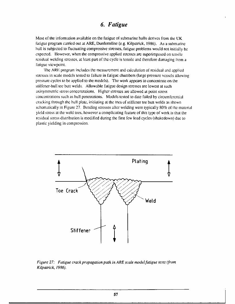
The ARE program includes the measurement and calculation of residual and appliedstresses in scale models tested to failure in fatigue chambers (large pressure vessels allowingpressure cycles to be applied to the models). The work appears to concentrate on thestiffener-hull tee butt welds. Allowable fatigue design stresses are lowest at suchaxisymmetric stress concentrations. Higher stresses are allowed at point stressconcentrations such as hull penetrations. Models tested to date failed by circumferentialcracking through the hull plate, initiating at the toes of stiffener tee butt welds as shownschematically in Figure 27. Bending stresses after welding were typically 80% of the materialyield stress at the weld toes, however a complicating feature of this type of work is that theresidual stress distribution is modified during the first few load cycles (shakedown) due toplastic yielding in compression.
Plating
Stiffener
Figure 27: Fatigue crack propagation path in ARE scale model fatigue tests (fromKilpatrick, 1986).
57
Fatigue of welded structures in general is reviewed in great detail by Gurney (1979a).
The following discussion is largely derived from that work. Consider a residual stress
distribution and a superimposed cyclic applied stress distribution. If the yield stress is notreached, then the total stress is simply the sum of the two components. If the yield stress isreached then plastic deformation occurs, and that part of the structure is subsequentlysubjected to a stress cycle which ranges from the yield stress downwards, regardless of thestress ratio of the applied stress. In many cases the residual stresses alone are of yield stressmagnitude so this condition is quite common.
As an example, consider a tensile residual stress of yield stress magnitude (or = O) witha cyclic applied stress ranging from -o2 to +01. The stress range is (o1 + 02) and the totalstress varies between Oy and oy - (o1 + 02). The fatigue behaviour is dependent only on thestress range and is independent of (applied) mean stress. Compressive applied stresses are
just as damaging as tensile stresses.Ignoring residual stress redistribution, and considering the zero-compression loading
applicable to a submarine hull (o in the discussion above), the total stress ranges from ordown to Or - O2. If 02 is less than or then the stress remains tensile throughout the cycle. If02 is greater than or then the total stress is compressive for part of the cycle, the damagingpart of the cycle is the stress range or to zero, and fatigue life should be independent of o2(unless a2 is sufficiently large to cause yielding in compression). It is clear that the fatigueassessment of a submarine hull design must encompass both tensile residual stresses and the(usually compressive) applied stresses.
7. Conclusion
Analytical solutions are available for a large number of shell structures with relatively simplegeometries (usually axisymmetric) typical of those found in submarines and other pressurevessels. They give a good picture of the general stress distribution due to geometricallysimple load distributions such as hydrostatic pressure. However, analytic solutions are notadequate for obtaining stresses at many structural details where fatigue cracking is likely toinitiate. For these details the analytical methods must be augmented by experimentalmethods or numerical computer calculations. A further difficulty in predicting fatiguebehaviour is the accurate calculation or measurement of residual stresses built into thestructuie during fabrication. Future work should address these questions.
2 One exception to this statement is when yielding in one area occurs in compression, resulting in the reduction of thebalancing residual tensile stress in an adjacent area. Fatigue crack tip plasticity also modifies the local residual stressdistribution.
58

8. References
Almroth, B.O., Brogan, F.A. and Stanley, G.M. (1980). Structural analysis of general
shells; user instructions for STAGSC- 1. California: Lockheed Palo Alto Research
Laboratory.
Atkins Research and Development Ltd (1982). ASASINL user manual. Surrey: Epsom)
Baker, E.H., Kovalevsky, L. and Rish, F.L. (1972). Structural analysis of shells. NewYork: McGraw Hill.
Bedri, R., McLeish, R.D. and Gill, S.S. (1983). Some observations on the calculation ofstresses due to local loads on cylindrical shells using BS 5500: Appendix G.International Journal of Pressure Vessels and Piping. 13, 227-25 1.
Bijlaard, P.P. (1954). Stresses from radial loads and external moments in cylindricalpressure vessels. Welding Journal Research Supplement, 33 (12), 615-623s.
Brebbia, C.A. (1985). Finite element systems - a handbook, 3rd edn. Berlin:Springer-Verlag.
Bushnell, D. (1974). Stress stability and vibration of complex, branched shells ofrevolution. Computers and Structures, 4, 399-435.
Bushnell, D. (1985). Computerized buckling analysis of shells. Dordrecht: Martinus
Nijhoff.
Bijlaard, P.P. (1955a). Stress from local loadings in cylindrical pressure vessels. Journal of
Applied Mechanics, 77 (6), 805.
Bijlaard, P.P. (1955b). Stresses from radial loads and external moments in cylindricalpressure vessels. Welding Journal Research Supplement, 34 (12), 608-617s.
Bijlaard, P.P. (1959a). Additional data on stresses in cylindrical shells under local loading.Welding Research Council Bulletin # 50.
Bijlaard, P.P. (1959b). Stresses in a spherical vessel from radial loads acting on a pipe.
Stresses in a spherical vessel from external moments acting on a pipe. Influence of areinforcing pad on the stresses in a spherical vessel under local loading. WeldingResearch Council Bulletin # 49.
Cloud, R.L. (1970). Pressure vessel ends. In, S.S. Gill (ed.) The stress analysis of pressure
vessels and pressure vessel components, pp. 167-218. Oxford: Pergamon.
Compton-Hall, R. (1989). The incredible shrinking submarine. New Scientist, 1 April 1989.
59

Decock, J. (1973). Determination of stress concentration factors and fatigue assessment offlush and extruded nozzles in welded pressure vessels. In 2nd InternationalConference on Pressure Vessel Technology, p. 821-834.
de Hart, R.C. (1969). External pressure structures. In, J.J. Myers, C.H. Holm andR.F. McAllister (eds.) Handbook of ocean and underwater engineering. New York:McGraw-Hill.
Durelli, A.J. (1981). Stress concentrations. In, G.C. Sih (ed.) Experimental evaluation ofstress concentration and intensity factors. The Hague: Martinus Nijhoff.
Eringen, A.C., Naghdi, A.K. and Thiel, C.C. (1965). State of stress in a circular cylindricalshell with a circular hole. WRC Bulletin # 102.
Faulkner, D. (1977). Effects of residual stresses on the ductile strength of plane weldedgrillages and of ring stiffened cylinders. Journal of Strain Analysis, 12 (2), 130-139.
Findlay, G.E. and Timmins, W. (1987). Local radial loads on cylinders: BS 5500Predictions v Experimental results. International Journal of Pressure Vessels andPiping, 27 (1), 33-48.
Flugge, W. (1960). Stresses in shells. Berlin: Springer-Verlag.
Friedman, N. (1984). Submarine design and development. Annapolis, Maryland: NavalInstitute Press.
Gibson, J.E. (1980). Thin shells - computing and theory. Oxford: Pergamon.
Gill, S.S. (1970). Basic principles. In, S.S. Gill (ed.) The stress analysis ofpressure vesselsandPV components, pp. 7-71. Oxford: Pergamon.
Gill, S.S., Leckie, F.A. and Penny, R.K. (1970). Pressure vessel branches. ibid pp. 73-116.
Gumey, T.R. (1975). Finite element analyses of some joints with the welds transverse to thedirection of stress (Research Report E/62/75). Cambridge: The Welding Institute.
Gurney, T.R. (1979a). Fatigue of welded structures, 2nd edn. Cambridge: CambridgeUniversity Press.
Gumey, T.R. (1979b). Stress intensity factors for cracks at the toes of transverse butt welds(Research Report 88/1979). Cambridge: The Welding Institute.
Hampe, E. (1964). Statik rotationssymmetrischerflachentragwerke. Berlin: VEB Verlagfdir Bauwesen.
Harvey, J.F. (1985). Theory and design ofpressure vessels. New York: Van NostrandReinhold.
60

Hoff, N.J. (1954). Boundary valve problems of the thin-walled circular cylinder Journal ofApplied Mechanics, 21, 343-350.
Hoff, N.J., Kempner, J. and Pohle, F.V. (1954). Line load applied along generators ofthin-walled circular cylindrical shells of finite length. Quarterly of AppliedMathematics, 11, 411-426.
Jane's (1989). Italy's small submarine aimed at export market. Jane's Defence Weekly,25 March 1989, p. 505.
Jones, R.F., Armen, H. and Fong, J.T. (1977). Numerical modeling of manufacturingprocesses. Winter Annual Meeting of ASME.
Kendrick, S. (1964). Structural design of submarine pressure vessels (U) (ReportNCRE-R483) (Unclassified report). Dunfermline, Fife: Naval Construction ResearchEstablishment.
Kendrick, S. (1970). Externally pressurized vessels. In, S.S. Gill (ed.) The stress analysisof pressure vessels and PV components, pp. 405-507. Oxford: Pergamon.
Kendrick, S. (1985). Ring-stiffened cylinders under external pressure. In, R. Narayanan(ed.) Shell structures - stability and strength, pp. 57-95. London: Elsevier AppliedScience.
Kilpatrick, I.M. (1986). The fatigue characteristics of submarine structures subjected toexternal pressure cycling. In Advances in marine structures, ARE, Dunfermline, May1986. London: Elsevier Applied Science.
Kitching, R. (1970). Local loading and local attachments. In, S.S. Gill (ed.) The stressanalysis of pressure vessels and PV components, pp. 221-265. Oxford: Pergamon.
Kraus, H. (1967). Thin elastic shells. New York: Wiley.
Krenzke, M.A. and Short, R.D. (1959). Graphical method for determining maximum stressesin ring-stiffened cylinders under external hydrostatic pressure (Report DTMB-R 1348).David Taylor Model Basin.
Leckie, F.A. and Penny, R.K. (1963). Stress concentration factors for the stresses at nozzleintersections in pressure vessels. WRC Bulletin # 90.
Lidbury, D.P.G. (1984). The significance of residual stresses in relation to the integrity ofLWR pressure vessels. International Journal of Pressure Vessels and Piping, 17 (4),197-328.
Masubuchi, K. (1980). Analysis of welded structures. Oxford: Pergamon.
61
Moshaiov, A. and Joelson, E.R. (1989). Theory and application of a bi-metal ring stiffenedcylinder under external pressure. Journal of Ship Research, 33 (4), 291-297.
Mershon, J.L., Mokhtarian, K., Ranjan, G.V. and Rodabaugh, E.C. (1984). Local stresses incylindrical shells due to external loadings on nozzles. WRC Bulletin 297.
Novozhilov, V.V. (1959). The theory of shells. Groningen: Noordhoff.
Peterson, R.E. (1974). Stress concentration factors. New York: Wiley.
Popov, E.P. (1978). Mechanics of materials, 2nd ed. Englewood Cliffs, NJ: Prentice-Hall.
Roberts, M.L. and Smith, C.S. (1988). Design of submarine structures. In, 1988 UnderseaDefence Technology Conference, London, Oct. 26-28, 1988, pp. 217-225. TunbridgeWells: Microwave Exhibitions and Publishers.
Salerno, V.L. and Puos, J.G. (1951). Stress distribution in a circular cylindrical shell underhydrostatic pressure supported by equally spaced circular ring frames (Report 171-A).Brooklyn: Poly. Inst.
Savin, G.N. (1961). Concentration of stress around holes (Translation). Oxford:Pergamon.
Shama, M.A. (1970). Cold forming residual stresses and their effect on the accuracy ofpost-forming operations. European Shipbuilding, 2, 23-26.
Short, R.D. and Bart, R. (1959). Analysis for determining stresses in stiffened cylindricalshells near structural discontinuities (Report DTMB-R1065). David Taylor ModelBasin.
Smith, C.S. 90 "'v ,,d W. (1977). lnflucnce of initial deformations and residual stresseson inelastic flexural buckling of stiffened plates and shells. In, P.J. Dowling,J.E. Harding and P.A. Frieze (eds.), Steel plated structures, pp. 838-863. London:Crosby Lockwood Staples.
Sokolnikoff, I.S. (1956). Mathematical theory of elasticity, 2nd ed. New York:McGraw-Hill.
Spence, J. and Carlson, W.B. (1967). A study of nozzles in pressure vessels under pressurefatigue loading. Proceedings of the Institute of Mechanical Engineers, 182 (31),657-684.
Stout, R.D. and Pense, A.W. (1965). Effect of composition and microstructure on the lowcycle fatigue strength of structural steels. Transactions of the ASME Journal of BasicEngineering, 87 (2), 269-274.
62

Teixeira, M.A., McLeish, R.D. and Gill, S.S. (1981). A simplified approach to calculatingstresses due to radial luads and moments applied to branches in cylindrical pressurevessels. Journal of Strain Analysis, 16 (4), 217-226.
Thompson, A.D.E. and Christopher, P.R. (1973). How materials properties affect the designof submersible structures. In, The Relevance of Fracture Toughness to the Design andReliability of Military Equipment (Symposium), The Welding Institute, Cambridge,England, June 11-13, 1973 (TTCP document).
Tooth, A.S. and Motashar, F.A. (1989). Radial loading of a cylindrical vessel through arectangular rigid attachment. International Journal of Pressure Vessels and Piping,37, 345-363.
Timoshenko, S.P. and Woinowsky-Krieger, S. (1959). Theory of plates and shells, 2nd ed.New York: McGraw-Hill.
Uddin, Md. W. (1987). Large deformation analysis of plate-end pressure vessels.International Journal of Pressure Vessels and Piping, 29, 46-65.
Viterbo, F. (1930). Sul problema della robustezza di cilindri cavi rinfortzati transversalmentesotto-posti da ogni parte a pressione esterna. L'Ingegnere IV, 446-456, 531-540 (alsoBu-Ships Translation 354, 1949).
von Mises, R. (1929). Der kritische aussendruck zylindrischer rohre. Stodola Festschrift,Zurich, pp. 418-430.
von Sanden, K. and Gunther, K. (1920). Uber das festigkeitsproblem quersteifterhohlzylinder unter allseitig gleichmissigem aussendrUck. Weerft und Reederei, 1 (8,9, 10). (Also DTMB Translation 38, 1952).
von Sanden, K. and Gunther, K. (1921). Weerft undReederei, 2 (17).
Watts, G.W. and Lang, H.A. (1952). The stresses in a pressure vessel with a flat headclosure. Transactions of the ASME, 74, 1083-1091.
Wcnk, E. (1961). Pressure vessel analysis of submarine hulls. Welding Journal, 40 (6),272s-288s.
Wilson, L.B. (1956a). The deformation under uniform pressure of a circular cylindricalshell supported by equally spaced circular ring frames. Part I -Asymptotic method(Report NCRE-R 337A). Dunfermline, Fife: Naval Construction ResearchEstablishment.
Wilson, L.B. (1956b). Part 2 - Fourier series method (Report NCRL-R 337B).Dunfermline, Fife: Naval Construction Research Establishment.
63

Wilson, L.B. (1956c). Part 3 - General discussion (Report NCRE-R 337C). Dunfermline,Fife: Naval Construction Research Establishment.
Young, W.G. (1989). Roark's formulasfor stress and strain, 6th ed. New York:McGraw-Hill.
64

Appendix 1
Von Sanden and Gunther (Ignoring End Pressure)
Differential Equation:
ElI(d 4w/dZ4) + Ehw/R 2 =-p3
Boundary Conditions:
w(Z) =w(Z)
dwldz =0 at z L/2
2E1 (d 3w/d/ ) - pb = Kw
Particular Solution of DE: w -pR2 / Eh
General Solution of DE:
w A sinh(ctz) sin(caz) + Bsinh(ctz) cos(ctz) + C cosh(caz) sin(az)
+ D cosh(wz) cos(cvz) - pR 2 / Eh
Solution of Boundary Value Problem:
w = - (pR2/Eh) [I + 2aX(KR 2 - bEh)(A sinh(caz) sin(ctz) - A +cosh(az) cos(az))]
d 2W/dZ2 - (pR2)/Eh) [4a&(KR 2 - bEh)(A +sinh(ciz) sin(az) + A cosh(az) cos(az))]
A+ = (sinh(aLI2) cos(aL/2) + cosh(aL/2) sin(aL/2)I /H-
A- = [sinh(axL/2) cos(axL/2) - cosh(aL/2) sin(cxL/2)] H
H = R 2Kat (sinh(cxL) + sin(ctL)lI + 2Eh [cosh(caL) - cos(aL)]
65

Frame Rigidity Constant:
K =E(Af +bh) / R
Stresses:
a m EE ~w/Rmembrane(Y '= Ec0m=E/
Ob = -[p/(-v2)](
bendingGob = a b
(p ranges from -h/'2 at the inner surface to +h/2 at the outer surface)
66

Appendix 2
Von Sanden and Gunther (Including End Pressure)
DE: El (d 4W/dZ4 ) + Ehw/R2 -- p(l _ V/2)
BCs: w(-z) =w(Z)
dw/dz =0 at z =L/2
2E1 (d'wldz3) -pb - Kw
Particular Solution of DE: w =-R p 2 (1 - v/2) / Eh
General Solution of DE:
w =A sinh(QZ.) sin(axz) + B sinh(Qxz) cos(Qxz) + C cosh(az) sin(cv.)+ D cosh(az.) cos(az) - pR 2 / (1 - v/2)
Solution of BVP:
w = - (pR 2/Eh) [(I - v/2) + 2ax(KR 2 - bEh)(A sinh(az) sin(czz) - A 4cosh(QZ) cos(az))l
d 2W/di3 = - (pR 2 fEh)[4&x (KR 2 - bEh)(A+ sinh(cz) sin(axz) + A cosh(cxz) cos(az))I
Stresses:
cr' = -pR/2hmembrane
CFOM = Ew/R+vazm
aYZb = - [Ep /(I1- v 2)1 (d2W/dZ2 )bending
(T0 b 7(F
67

Appendix 3
Viterbo
DE: El (d4w/dz4 ) + Ehw/R 2 =- p(l - v/2)
BCs: w(-z) = w(z)dw/dz = 0 at z = L/22EI (d3w/dz3 ) - pb (I - v/2) = Kw S
Particular Solution of DE: w = - pR 2 (1 - v/2) / Eh
General Solution of DE:
As for Von Sanden and Gunther (Including end pressure)
Solution of BVP:
w = - [pR2 (1 - v/2)/Eh][1 + 2aKR2 - bEh)(A sinh(az) sin(az) - A+cosh(az) cos(az))]
d2w/dz2 = - IpR 2(1 - v/2)/Eh)[4ot3 (KR 2 - bEh)(A+sinh(zz) sin(c,) + A cosh(oz) cos(cxz))]
Frame Rigidity Constant: K = E (Af + bh) / R2
Stresses:tzm = -pR/2h
CFO M = Ew / R + vczm
azb = - [Ep / (1 - v2 )] (d2 w/dz2)
G0 b = Vz b
1i8

Appendix 4
Salerno and Pulos
DE: El (d4w/dz4) + (pR/2) (d2w/dz2) + Ehw/R 2 = - p(l - v/2)
BGs: w(-z) = w(z)dw/dz = 0 at z L/22El (d3w/d. 3) - pb(l - v/2) = Kw
Particular Solution of DE: w =- pR 2 (1 - v/2) / Eh
General Solution of DE:
w = a exp( lz) + b exp(X2z) + c exp(X3z) + d exp(X4 z)- pR2(l - v/2) / Eh
with X, the roots of
4 + (pR/2EI) X2 + (hw/R 21) = 0
giving X = + 2 P/P* p+- -(/I*) 1]}12
where p* = 2hE/R 3oX2 = 2h 2E/R 2 "3(1 - v2)
= critical pressure for axisymmetric elastic buckling of an unstiffened cylinder underuniform axial pressure.
As X,1 - 2 {2 [- p/p* + (p/p*)2 1]11/2
and 1 =2 4 = {22 [ P/P*- (p/p,) 2 - 1,12
the general solution reduces to:
w = Asinh(X.z) + B cosh(X.z) + C sinh(k 3 z) + D cosh(. 3 z)- pR (1 - v/2) / Eh
d2w/dz 2 = A, 12 sinh(kqz) + B, 1
2 cosh(kz) + CX32 sinh(X.3 z) + DX3
2 cosh(X3z)
69

Solution of BVP:
A C C=0
D =-B [XI sinh (X IL/2)J / [),3 sinh (X3L/2)]
B p(l - v/2) (KR2 - bEh) X3 sinh (),3L/2)
Eh [G1X.- sinh (X3L/2) - G3 X, sinh (?,,L/2)]
where =i 2E I X'sinh (XiL/2) - K cosh (XiL/2)
Stresses:
at m = -pR/2h
CY0 = Ew/R+var zm
UZb = - [Ep /(1-v)]Id 2w/dZ2
70

Appendix 5
Wilson's Asymptotic Method
DE: El (d4 w/dz4 ) + (pR/2) (d2 w/dz2) + Ehw / R2 - p(l - v/2)
BCs: w(-z) = w(z)dw/dz = 0 at z = L/22EI (d3w/dz 3) - pb(1 - v/2) = Kw
Assumed Form of Solution:
W = pw I + p 2 w 2
Resulting Pair of BVPs for w1 and w2:
El (d4W /dz 4) + Ehw I / R2 = - (1 -v/2)
w1 (-z) = w1(z)
dw1/dz = 0 at z = L/2
2El (d3W /dz 3) - b(l - v/2) = Kw 1
El (d4w2/dz 4) + Ehw 2 / R2 = - (R/2) (d2 Wl/dZ2 )
W2 (-Z) = W2 (z)
dw 2/dz = 0 at z = L/2
2EI (d3 Wz/d3 = Kw 2
Solutions of BVPs:
w = pw1 is the linear, Viterbo solution.
W. = C1 sinh(az) sin(oz) + C2 cosh(az) cos(az) + C3z sinh(coz) cos(az)+ C4z cosh(ctz) sin(o.z)
C1, C2, C3 and C4 are determined from the boundary conditions. Fairly
complicated expressions result, as shown by Wilson (1956a).
71
Frame Rigidity Constant (K): As for Wilson's Fourier Series Method.
Stresses: As for Wilson's Fourier Series Method.
72

Appendix 6
Wilson's Fourier Series Method
DE: El (d4w/dz4) + (vEI/R 2 + pR/2) d2 w/dz2 + Ehw / R 2 - p(l - v/2)
BCs: w(-z) = w(z)dw/dz = 0 , at z = L/22El (d3w/dz3) - pb(1 - v/2) = Kw
Assumed Form of Solution:
00
w(z) = W(o) + (2/7t) I W(n) cos (27nz/L)n=1
(n) = w(27tz/L) cos(27Tnz/L) dz
0
Fourier coefficients
Solution of BVP: See Wilson (1956b).
Stresses:
m = - pR / 2h membrane
GOm = Ew / R + vyzm
rzb = - Ep [vw/R2 + (d2w/dz2)] / (1 - v2) bending
(Y b = - Ep [w/R 2 + V (d2w/dz2 )] / (1 - V2)
(p ranges from -h/2 at the inner surface to +h/2 at the outer surface of the shell),
Frame Rigidity Constant:
K = E(Af/Rf + bh/R 2) + 3E(I /Rf 4 + bh3/12R 4) * E(A/Rf2 + bh/R 2)
73

Appendix 7
Stress Concentration due to Bulkhead or Heavy Frame
Calculation of the hull plating deflection using equation (55) in Section 5.6.3 requiresknowledge of the rigidity constant KH for the heavy frame. The special cases Ku1 = K (thenormal ring stiffener rigidity constant) and K,, = 00 (perfectly rigid bulkhead) have beendiscussed in Section 5.6.3. Expressions presented here allow KH to be calculated ftrintermediate cases. The deflection can then be calculated using equation (55) and thestresses using expressions in Appendix 6.
The assumption is made that the additional deflection due to the heavy frame is the samefor a uniformly framed cylinder as for an infinite cylindrical shell. This is a reasonableassumption for typical submarine hull deflections and frame spacings.
For the case of frames only moderately more rigid than the normal frames, Wilson's(1956c) expressions for K in Appendix 6 may be used.
Wilson (1956c) also gives an expression for deep frames (depth > 0.2 x shell radius):
Ktl = Eb (tf + h) / R 2 + ER12 / R [(I + v)p - (I _ v)*R12]
where tf and additional parameters are defined in Figure A7-1 and:
;: RI 2 R22 [Eh w ± (I - v) R2 ] / S
S +R 2 [Eh w T (I + v) R2 f/ S
Xf = Ehff/a 2
S = hR 12 [Eh w -;- (I + v) R2XfI - hwR 2
2 [Eh, ± (1 - v) R2X.l
The upper and lower signs refer to external and internal frames respectively.For a bulkhead idealized as a flat circular plate of thickness t and radius R, Sokolnikoff
(1956) shows that the radial deflection and stresses due to uniform radial pressure p on thecircumference are:
wr = -p(l+v)(1-2v)r/E
Or = ( 0 = -p
Therefore the rigidity constant is:
KII = tE/R(I +v)(l - 2v)
74
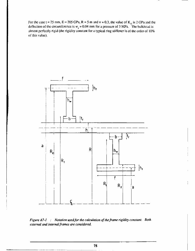
For the case t = 25 mm, E = 205 GPa, R = 5 m and v = 0.3, the value of K1 is 2 GPa and thedeflection of the circumference is wr = 0.04 mm for a pressure of 3 MPa. The bulkhead isalmost perfectly rigid (the rigidity constant for a typical ring stiffener is of the order of 10%of this value).
f
F--- ---- h,
b It
aR2 R ,,,
l- . .. l - -: -t hf
RI RZ a
Figure A7-1 Notation used for the calculation of the frame rigidity constant. Bothexternal and internalframes are considered.
75

SECURITY CLASSIFICATION OF THIS PAGE UNCLASSIFIED
DOCUMENT CONTROL DATA SHEET
REPORT NO. AR NO. REPORT SECURITY CLASSIFICATION
MRL-TR-90-26 AR-006-326 Unclassified
TITLE
Analytical Calculations of Fatigue Loading of Submarine Hulls
AUTI OR(S) CORPORATE A UTI IORDSTO Materials Research Laboratory
I.M. Robertson PO Box 50Ascot Vale Victoria 3032
REPORT DATE TASK NO. SPONSOR
November, 1990 NAV 88/152 DNA
FII.E NO. REFERENCES PAGES
G6/4/8-3901 73 76
CIASSIICATION/LIMITATION REVIEW DATE CLASSIFICATION/RELEASF, AUT IORITY
Chief, Materials Division
SECONDARY DISTRIBUI1ON
Approved for public release
ANNOUNCEMENT
Announcement of this report is unlimited
KIYWORDS
Stress Weld
Stress Concentration Ring Stiffened Cylinder
SUBJECT GROUPS
ABSIRACT
Fatigue is a potential failure mode of submarine pressure hulls. Australia's new Type 471 submarines will be constructedfrom a new high strength steel. The higher design loadings made possible by the higher strength make fatigue an evenmore significant consideration than in other designs. The stress analysis of submarine pressure !, Ils under hydrostaticloading is reviewed. The main emphasis is on analytical methods of calculation as opposed to numerical (e.g. finiteelement) methods, and on the calculation of the fatigue loading rather than the calculation of buckling pressure. Becauseof the emphasis on fatigue, stress concentrations, residual stresses and the interaction between residual and appliedstresses are considered.
SECURITY CLASSIFICATION OF TI[IS PAGE
UNCLASSIFIED