lcd solenoid design reinforced conductor r&d magnet services ild workshop, lal/paris, may 22-25,...
TRANSCRIPT

LCD Solenoid DesignReinforced Conductor R&D
Magnet ServicesILD Workshop, LAL/Paris, May 22-25, 2011
Andrea Gaddi & Benoit CuréPhysics Dept. - CERN

Page 2May 22-25, A. Gaddi & B. Curé, Physics Dept. CERN
LCD Solenoid, Conductor R&D, Magnet Services
CLIC_Detector central solenoids main parameters.

Page 3May 22-25, A. Gaddi & B. Curé, Physics Dept. CERN
LCD Solenoid, Conductor R&D, Magnet Services
CLIC_SiD Simulated Magnetic Field.
The field map displays the magnetic flux densityvector sum in Tesla.
The model is made using the ANSYS magnetic vector potential formulation with the nodal-based method.Infinite boundaries are used.
The model is axis-symmetric. Taking into account the median transversal plan symmetry , only ¼ is modeled.
The iron yoke filling factor is 100%. The iron properties are taken from CMS iron measurements.The field is 5T at IP.
Nota bene:CLIC_SiD has been studied first because is the most challenging one. This study represents therefore a proof-of-principle for the CLIC_ILD case.
Page 4May 22-25, A. Gaddi & B. Curé, Physics Dept. CERN
LCD Solenoid, Conductor R&D, Magnet Services
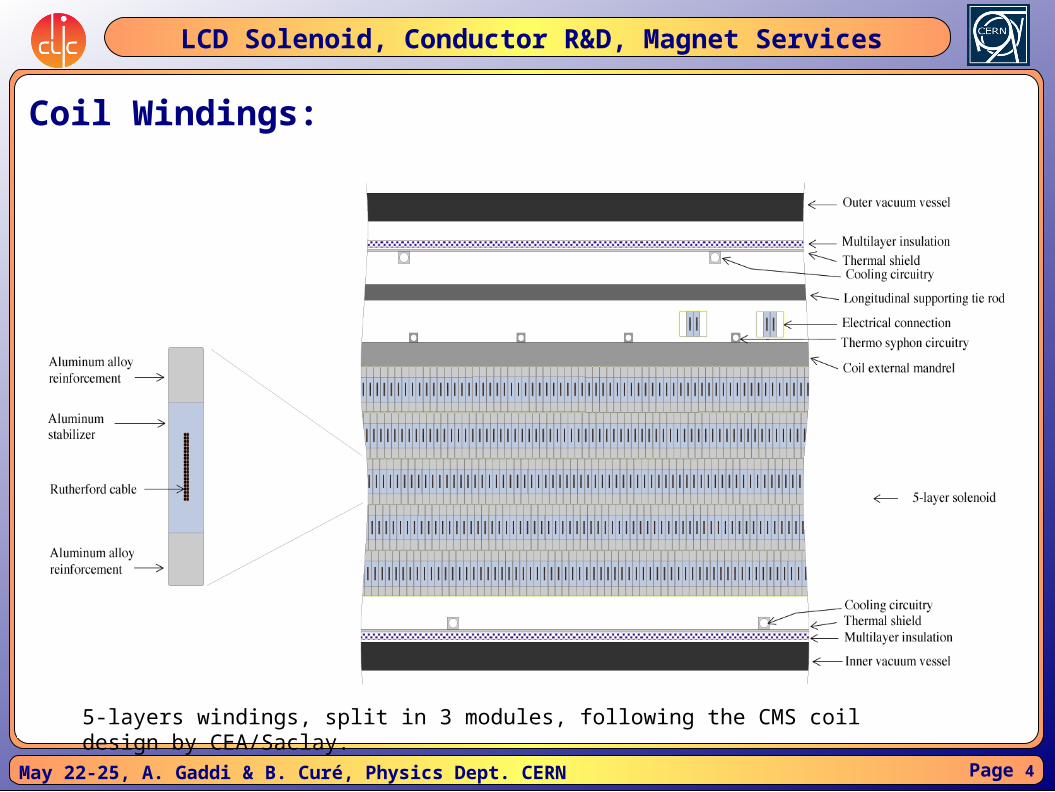
Coil Windings:
5-layers windings, split in 3 modules, following the CMS coil design by CEA/Saclay.
Page 5May 22-25, A. Gaddi & B. Curé, Physics Dept. CERN
LCD Solenoid, Conductor R&D, Magnet Services
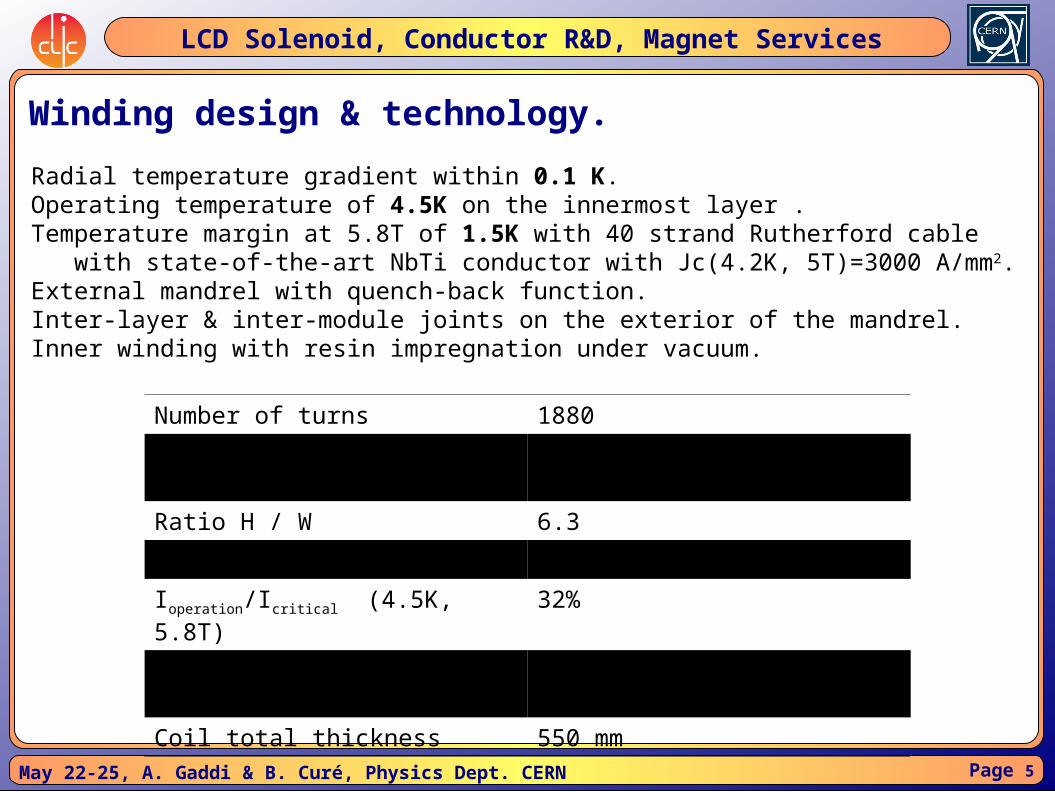
Winding design & technology.
Number of turns 1880
Conductor dimensions H x W 97.4A mm x 15.6 mm
Ratio H / W 6.3
Conductor unit length 2.7 km
Ioperation/Icritical (4.5K, 5.8T) 32%
External cylinder thickness 50 mm
Coil total thickness 550 mm
Radial temperature gradient within 0.1 K.Operating temperature of 4.5K on the innermost layer .Temperature margin at 5.8T of 1.5K with 40 strand Rutherford cable with state-of-the-art NbTi conductor with Jc(4.2K, 5T)=3000 A/mm2.External mandrel with quench-back function.Inter-layer & inter-module joints on the exterior of the mandrel.Inner winding with resin impregnation under vacuum.

Page 6May 22-25, A. Gaddi & B. Curé, Physics Dept. CERN
LCD Solenoid, Conductor R&D, Magnet Services
Superconductor options.

Page 7May 22-25, A. Gaddi & B. Curé, Physics Dept. CERN
LCD Solenoid, Conductor R&D, Magnet Services
Anti-solenoid study.

Page 8May 22-25, A. Gaddi & B. Curé, Physics Dept. CERN
LCD Solenoid, Conductor R&D, Magnet Services
Anti-solenoid study.
Courtesy A. Bartalesi

Page 9May 22-25, A. Gaddi & B. Curé, Physics Dept. CERN
LCD Solenoid, Conductor R&D, Magnet Services
Magnet Services & push-pull scenario.
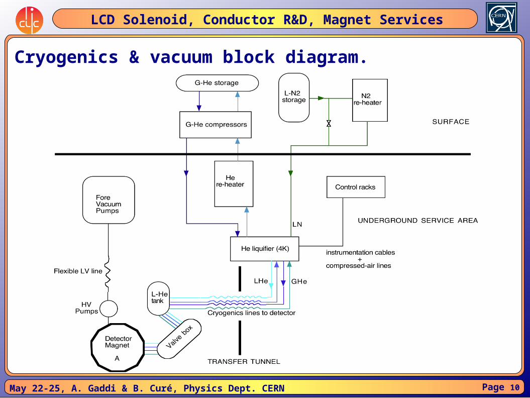
The two most challenging magnet services are the cryogenics & vacuumsystem and the powering & protection one. The He liquifier is an heavy and delicate components that cannot move with the detector, neither sit too close, due to the magnetic stray field. Its ideal location is the side service cavern, along with the fore vacuum pumps, that are noisy in terms of vibration and need easy access for maintenance.
The power supply, and its associated breakers, is also a huge and heavy component whose location is better chosen in the service cavern. On the contrary, the dump resistors protecting the coil, should stay as close as possible to the magnet, but consideration on the total energy (> 1GJ) dissipated in the cavern may lead to move them away from the detector.
Page 10May 22-25, A. Gaddi & B. Curé, Physics Dept. CERN
LCD Solenoid, Conductor R&D, Magnet Services
Cryogenics & vacuum block diagram.

Page 11May 22-25, A. Gaddi & B. Curé, Physics Dept. CERN
LCD Solenoid, Conductor R&D, Magnet Services
Magnet powering block diagram / different options.

Page 12May 22-25, A. Gaddi & B. Curé, Physics Dept. CERN
LCD Solenoid, Conductor R&D, Magnet Services
Drawing by N. Siegrist

Page 13May 22-25, A. Gaddi & B. Curé, Physics Dept. CERN
LCD Solenoid, Conductor R&D, Magnet Services
Flexible cryo & vacuum lines.
The detector solenoid has to stay cold during the push-pull period, i.e. liquidHelium has to be guaranteed via flexible transfer lines. Vacuum inside thecoil cryostat could be kept by simple cryo-pumping during push-pull, but a flexiblerough vacuum line is necessary anyhow.
CMS has 30m long rigid cryo transfer line, vacuum insulated+ 50m long rigid 230mm primary vacuum line (10-3 mbar)Not applicable to push-pull.
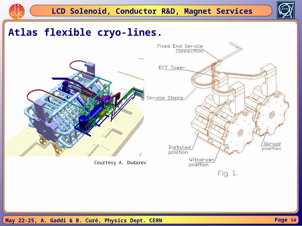
Flexible cryolines have been successfully installed to cool Atlas Endcap ToroidsLHe lines diameter 58mmOuter shielding 110mmVacuum envelope 143mm
SiD foresees a flexible cryoline 160mm, vacuum insulated
Page 14May 22-25, A. Gaddi & B. Curé, Physics Dept. CERN
LCD Solenoid, Conductor R&D, Magnet Services
Atlas flexible cryo-lines.
Courtesy A. Dudarev

Page 15May 22-25, A. Gaddi & B. Curé, Physics Dept. CERN
LCD Solenoid, Conductor R&D, Magnet Services
Atlas flexible service-lines.
Courtesy A. Dudarev

Page 16May 22-25, A. Gaddi & B. Curé, Physics Dept. CERN
LCD Solenoid, Conductor R&D, Magnet Services
Flexible HTS bus-bars.
Despite the fact that during push-pull, the detector magnet is obviously off,a permanent connection of the solenoid power supply to the coil current leadswould save precious time and avoid risks associated with manipulation.This line shall be able to carry 20kA in a self-field of about 0.6T, over a lengthof some 60m. A flexible resistive line would take too much space in the cavernand have a significant voltage drop V (in addition to the power dissipated P=VxI).
CERN is actually developing the design of a semi-flexible, vacuum insulated,HTS (MgB2) line for the LHC upgrade.The characteristics of this powering line are the following: Nominal current: 110kA at 20K and 0.8T Maximum current: 130kA at 20K and 0.8T Cooling: GHe, from 5 to 20K Length: 100m Vacuum envelope: 90mm Minimum bending radius: 1.5m

Page 17May 22-25, A. Gaddi & B. Curé, Physics Dept. CERN
LCD Solenoid, Conductor R&D, Magnet Services
Proposal for powering lines : flexible HTS bus-bars.Prototypes of the multi-cables HTS powering line (courtesy A. Ballarino)

Page 18May 22-25, A. Gaddi & B. Curé, Physics Dept. CERN
LCD Solenoid, Conductor R&D, Magnet Services
Proposal for dump-system : compact water-cooled resistors.
Total stored magnetic energy ≈ 2.50 GJEnergy extracted by dumping system ≈ 1.25 GJSolenoid reference current (I) ≈ 20 kASolenoid inductance (L= 2E/I2) ≈ 12.5 HDump resistance (R) ≈ 30 mDischarge voltage ≈ 300 V wrt groundPeak discharge power (Ppeak=I2R) ≈ 12 MWDischarge time constant (t=L/R) ≈ 416 s

Page 19May 22-25, A. Gaddi & B. Curé, Physics Dept. CERN
LCD Solenoid, Conductor R&D, Magnet Services
Simulation done by F. Ramos

Page 20May 22-25, A. Gaddi & B. Curé, Physics Dept. CERN
LCD Solenoid, Conductor R&D, Magnet Services
Stray field considerations. Requirement for the magnetic field outside of detector is an important factor
which defines the amount of iron in the detector (or degree of compensation for endcap hybrid-design).
Effects of any field outside of detectors on the beam shall be corrected, and the requirements should come from human safety factor, from the limit of field map distortion due to off-beamline detector and from effects on cavern equipment.
From personnel safety considerations, field on any external surface of the detector shall be less than 200mT, while the field in non-restricted area (including near the off-beamline detector) shall be less than 10mT.
The magnetic field effect from the off-beamline detector onto the on-beamline detector must limit distortion of magnetic field map of the latter, anywhere inside its tracking volume.
The design criteria assumed for LCD Magnets is to have less than 5mT magnetic field induction at 15m distance from the detector axis.
Page 21May 22-25, A. Gaddi & B. Curé, Physics Dept. CERN
LCD Solenoid, Conductor R&D, Magnet Services
Conclusion & work-plan for the future. Further studies on coil winding, thermosyphon flow, quench protection. We can
run the same study for CLIC_ILD and eventually adapt drawings and tables to make this work compatible with ILC_DBD.
Conductor R&D: trial extrusion & cold working of a large cross-section conductor, with Ni doped stabilizer (CERN/KEK collaboration). Measurements of mechanical & electrical characteristics at room and liquid He temperature (CERN/KEK/INFN).
Coil instrumentation: development of optical fiber based temperature, strain & B-field sensors, to be embedded into the coil windings.
Anti-solenoid: further study on current optimization and possibly construction of a short length prototype.
The effects of the stray-field will be carefully looked. Any effort to limit the stray-field via an optimized yoke design and/or the use of tunable coils on the yoke endcaps will be pursued.

Page 22May 22-25, A. Gaddi & B. Curé, Physics Dept. CERN
LCD Solenoid, Conductor R&D, Magnet Services
Conclusion & work-plan for the future. The push-pull scenario leads to an integrated design of detector infrastructures.
Integration of magnet services with cavern layout requires a close collaboration with the civil engineering group.
A compromise between on-board services and a remote “service block” has to be found, making use of cable-chains that assure permanent connections with the service block, allowing a smooth movement of the detector during the push-pull operation.
Cryogenics and vacuum flexible lines have been already successfully used at Atlas. Need to be adapted to CLIC detector magnet. An existing R&D program for a HTS powering line for LHC upgrade could give good indications for a 20kA HTS line cooled with GHe between 5 and 20K, to be employed for detector magnet power-lines.
The problem of a compact on-board dump-system could be solved with a water-cooled resistor-bench. A 1/10 scale prototype could be useful to validate our simulations.