lcd-dmd installation and usage instructions sega … sega 192x64.pdf · lcd-dmd installation and...
TRANSCRIPT
LCD-DMD
Installation and Usage InstructionsSega Large Screen
V0.1 July 2014
Copyright 2014 Dr Pinball
ImportantPlease check Appendix A for details of machines that are compatible with LCD-DMD. It is important to note that LCD-DMD has not been tested on all of these machines – it is the responsibility of the user to make a final decision about the suitability of this system for use on a particular pinball machine.
The user installs LCD-DMD entirely at their own risk – Dr Pinball cannot accept responsibility for damage or other problems caused by this system or its use.
The installation instructions are given purely as a guide. The user must exercise caution when performing the installation.

Installation
Step 1 - Preparation
Switch off the pinball machine and remove the plug from the wall outlet.
Remove the backbox translite glass. Remove the speaker panel and place onto the pinball machine – use magnets or blutac on the side rails to stop the speaker panel from slipping.
You may also need to open the backbox light door to gain access to the cabling inside.
Step 2 – Remove the DMD plasma display
Figure 1 shows the DMD controller board. Remove the data ribbon cable and power connector from the board. Also remove the display ribbon cable from the DMD screen. These cables are marked in the figure.
Figure 1 – DMD Controller, remove marked cables
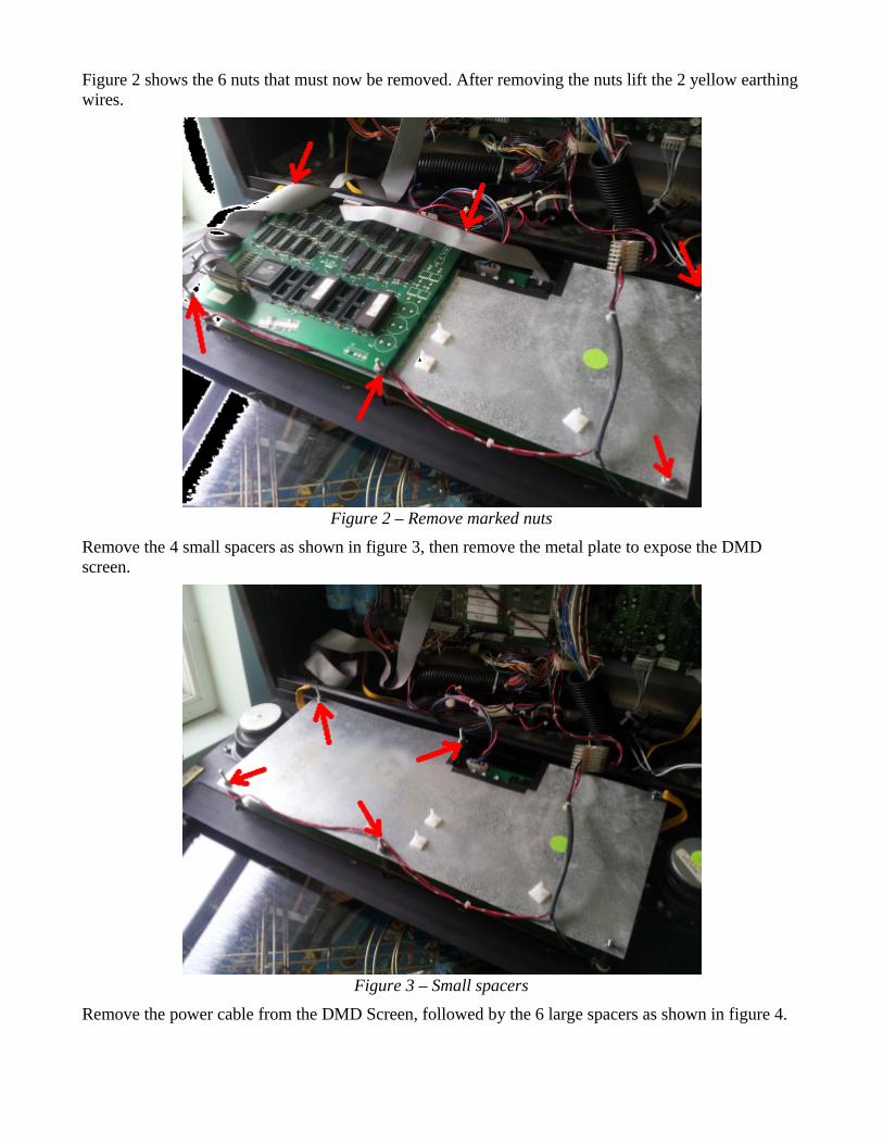
Figure 2 shows the 6 nuts that must now be removed. After removing the nuts lift the 2 yellow earthing wires.
Figure 2 – Remove marked nuts
Remove the 4 small spacers as shown in figure 3, then remove the metal plate to expose the DMD screen.
Figure 3 – Small spacers
Remove the power cable from the DMD Screen, followed by the 6 large spacers as shown in figure 4.

Figure 4 – Power cable and large spacers
Now carefully lift the DMD Screen away from the speaker panel.
Step 3 – Prepare the speaker panel
It is necessary to remove the centre top mounting post as shown in figure 5.
Figure 5 – Centre top mounting post
First, remove the translite mounting strip from the speaker panel. Start by removing the staples that hold the mounting strip in place, as shown in figure 6. Use a small flat bladed screw driver to pries the
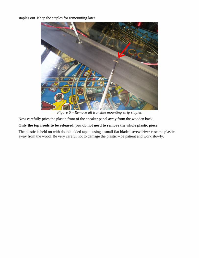
staples out. Keep the staples for remounting later.
Figure 6 – Remove all translite mounting strip staples
Now carefully pries the plastic front of the speaker panel away from the wooden back.
Only the top needs to be released, you do not need to remove the whole plastic piece.
The plastic is held on with double-sided tape – using a small flat bladed screwdriver ease the plastic away from the wood. Be very careful not to damage the plastic – be patient and work slowly.
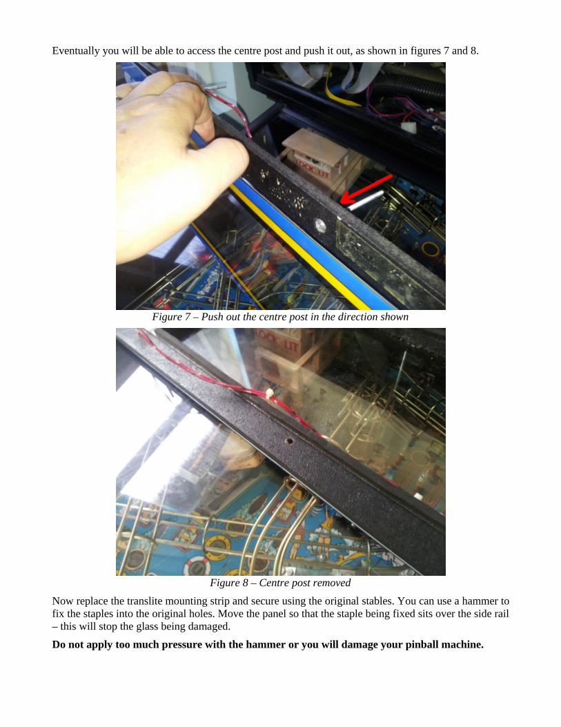
Eventually you will be able to access the centre post and push it out, as shown in figures 7 and 8.
Figure 7 – Push out the centre post in the direction shown
Figure 8 – Centre post removed
Now replace the translite mounting strip and secure using the original stables. You can use a hammer to fix the staples into the original holes. Move the panel so that the staple being fixed sits over the side rail – this will stop the glass being damaged.
Do not apply too much pressure with the hammer or you will damage your pinball machine.

Figure 9 – Locate the staple over the side rail when using the hammer
At this point you may wish to clean the plastic window before installing the LCD-DMD.
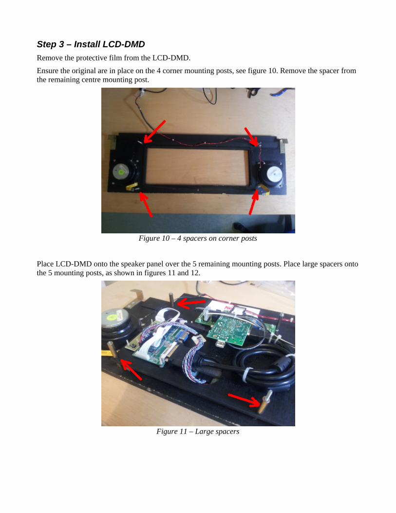
Step 3 – Install LCD-DMD
Remove the protective film from the LCD-DMD.
Ensure the original are in place on the 4 corner mounting posts, see figure 10. Remove the spacer from the remaining centre mounting post.
Figure 10 – 4 spacers on corner posts
Place LCD-DMD onto the speaker panel over the 5 remaining mounting posts. Place large spacers onto the 5 mounting posts, as shown in figures 11 and 12.
Figure 11 – Large spacers
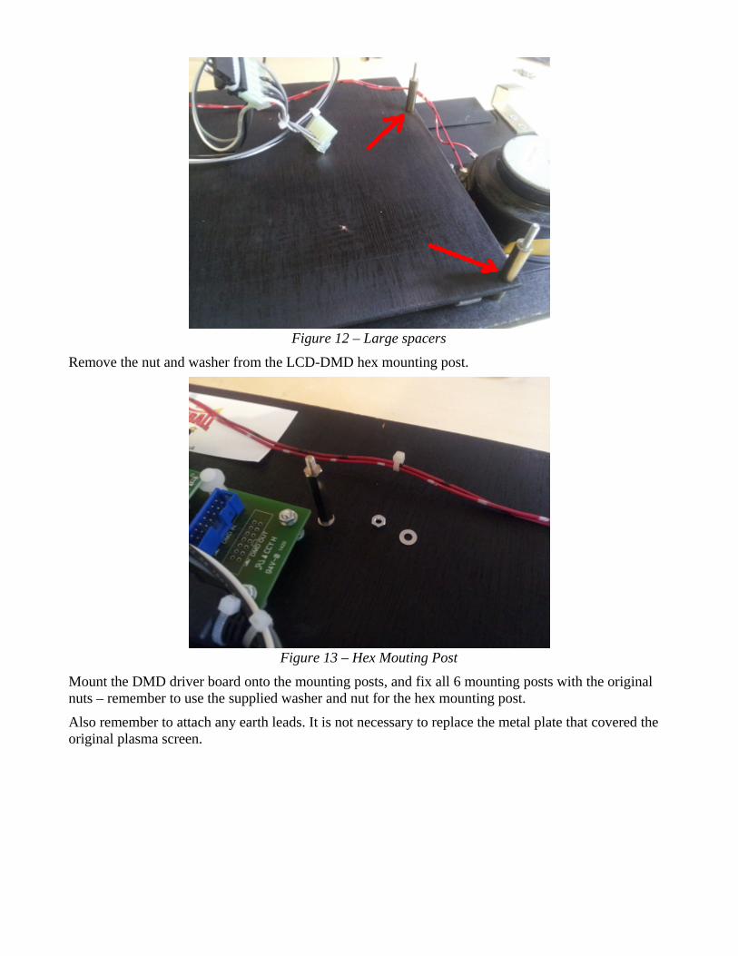
Figure 12 – Large spacers
Remove the nut and washer from the LCD-DMD hex mounting post.
Figure 13 – Hex Mouting Post
Mount the DMD driver board onto the mounting posts, and fix all 6 mounting posts with the original nuts – remember to use the supplied washer and nut for the hex mounting post.
Also remember to attach any earth leads. It is not necessary to replace the metal plate that covered the original plasma screen.
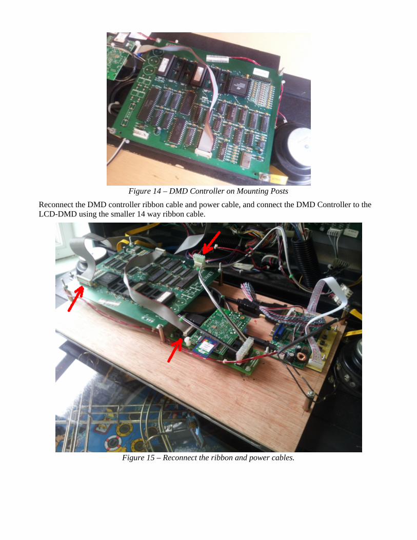
Figure 14 – DMD Controller on Mounting Posts
Reconnect the DMD controller ribbon cable and power cable, and connect the DMD Controller to the LCD-DMD using the smaller 14 way ribbon cable.
Figure 15 – Reconnect the ribbon and power cables.
Step 5 – Connect Power Cable
The power cable plugs are keyed to ensure correct orientation. It is important the key is correctly located when connecting plug to socket. Failure to correctly connect the plug may result in damage to your pinball machine.
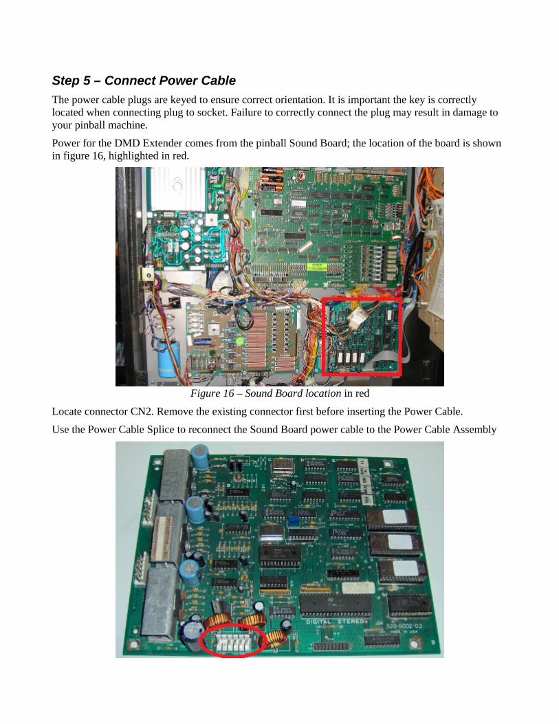
Power for the DMD Extender comes from the pinball Sound Board; the location of the board is shown in figure 16, highlighted in red.
Figure 16 – Sound Board location in red
Locate connector CN2. Remove the existing connector first before inserting the Power Cable.
Use the Power Cable Splice to reconnect the Sound Board power cable to the Power Cable Assembly
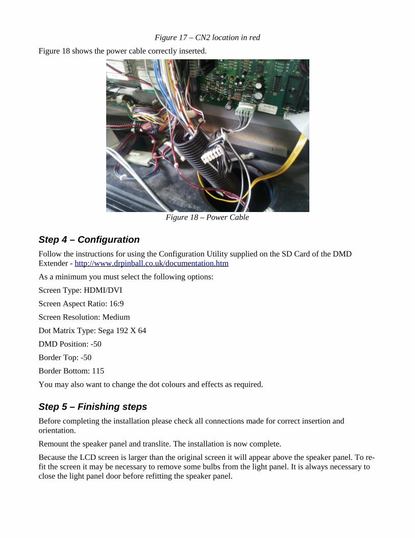
Figure 17 – CN2 location in red
Figure 18 shows the power cable correctly inserted.
Figure 18 – Power Cable
Step 4 – Configuration
Follow the instructions for using the Configuration Utility supplied on the SD Card of the DMD Extender - http://www.drpinball.co.uk/documentation.htm
As a minimum you must select the following options:
Screen Type: HDMI/DVI
Screen Aspect Ratio: 16:9
Screen Resolution: Medium
Dot Matrix Type: Sega 192 X 64
DMD Position: -50
Border Top: -50
Border Bottom: 115
You may also want to change the dot colours and effects as required.
Step 5 – Finishing steps
Before completing the installation please check all connections made for correct insertion and orientation.
Remount the speaker panel and translite. The installation is now complete.
Because the LCD screen is larger than the original screen it will appear above the speaker panel. To re-fit the screen it may be necessary to remove some bulbs from the light panel. It is always necessary to close the light panel door before refitting the speaker panel.
Appendix AThis appendix gives details of machines that are compatible with the LCd-DMD. It is important to note that LCD-DMD has not been tested on all of these machines – it is the responsibility of the user to make a final decision about the suitability of this system for use on a particular pinball machine.
The user installs LCD-DMD entirely at their own risk – Dr Pinball can accept no responsibility for damage or other problems caused by this system.
If your machine is not listed below please contact us at [email protected].
Maverick
Mary Shelley's Frankenstein
Baywatch
Batman Forever