lc and quartz oscillators -...
TRANSCRIPT

Universität Karlsruhe (TH) Research University•founded 1825in der Helmholtz - Gemeinschaft
Forschungszentrum Karlsruhe
by Manfred Thumm and Werner Wiesbeck
LC and Quartz Oscillators
Institut für Hochfrequenztechnik
und ElektronikIHE
2
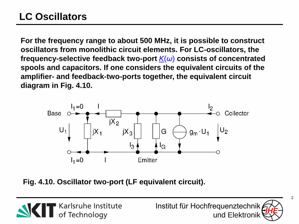
For the frequency range to about 500 MHz, it is possible to construct
oscillators from monolithic circuit elements. For LC-oscillators, the
frequency-selective feedback two-port K(ω) consists of concentrated
spools and capacitors. If one considers the equivalent circuits of the
amplifier- and feedback-two-ports together, the equivalent circuit
diagram in Fig. 4.10.
Fig. 4.10. Oscillator two-port (LF equivalent circuit).
LC Oscillators
Institut für Hochfrequenztechnik
und ElektronikIHE
3
If positive inductances and capacitances are assumed (XL = ωL, XC = -1/ωC),
then the following applies for the reactive elements X1, X2, and X3:
(G+gm)X1 + GX2 = 0, thus |X2| > |X1| since G, gm are positive and real.
Further analysis reveals a further equation: X1 + X2 + X3 = 0. In summary, the
following results apply:
X1 and X2 must be of opposite reactance type, and the reactance type of X2
must be that of X1 + X2.
X3 and the series combination of X1 and X2 are of opposite reactance type,
i.e. the reactance type of X3 is the same as that of X1.
In the course of time empirical and theoretical developments led to the circuit
variations shown in Fig. 4.11. Fig. 4.12 summarises the basic circuits for the
oscillator types described in Fig. 4.11.
Classification of LC Oscillators (I)

Institut für Hochfrequenztechnik
und ElektronikIHE
4
Fig. 4.11.
Systematics of LC-oscillators
(different combinations of the
dummy impedances X1, X2,
and X3, ).
Classific. of LC Oscillators (II)

Institut für Hochfrequenztechnik
und ElektronikIHE
5
Fig. 4.12.
LC-oscillators
from Fig. 4.11.
In three basic
circuits.
Classification of LC Oscillators (III)
Institut für Hochfrequenztechnik
und ElektronikIHE
6
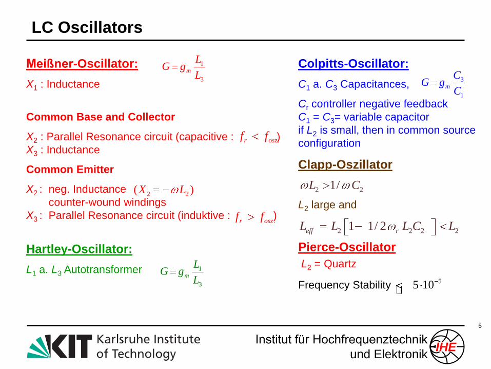
Colpitts-Oscillator:
C1 a. C3 Capacitances,
Cr controller negative feedback
C1 = C3= variable capacitor
if L2 is small, then in common source
configuration
Clapp-Oszillator
L2 large and
Pierce-Oscillator
L2 = Quartz
Frequency Stability
Meißner-Oscillator:
X1 : Inductance
Common Base and Collector
X2 : Parallel Resonance circuit (capacitive : )
X3 : Inductance
Common Emitter
X2 : neg. Inductance
counter-wound windings
X3 : Parallel Resonance circuit (induktive : )
Hartley-Oscillator:
L1 a. L3 Autotransformer
.r oszf f
.r oszf f
1
3
m
LG g
L
2 2( )X L
3
1
m
CG g
C
2 21/L C
2 2 2 21 1/ 2eff rL L L C L
55 10
1
3
m
LG g
L
LC Oscillators
Institut für Hochfrequenztechnik
und ElektronikIHE
7
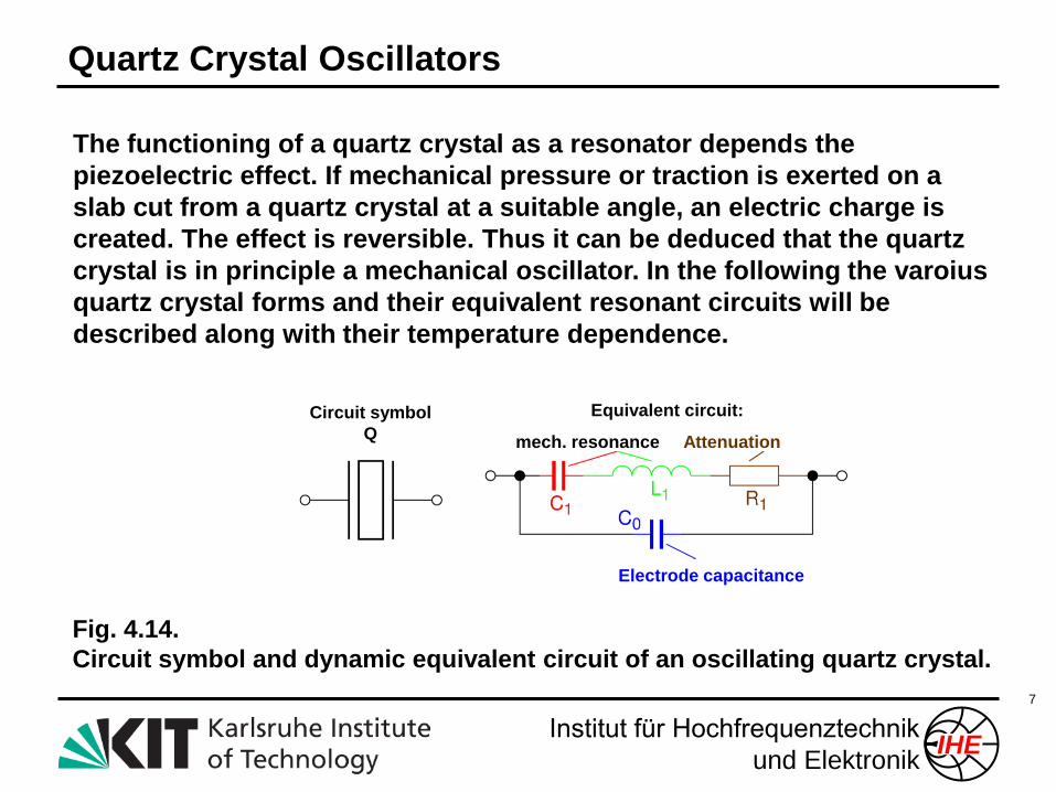
The functioning of a quartz crystal as a resonator depends the
piezoelectric effect. If mechanical pressure or traction is exerted on a
slab cut from a quartz crystal at a suitable angle, an electric charge is
created. The effect is reversible. Thus it can be deduced that the quartz
crystal is in principle a mechanical oscillator. In the following the varoius
quartz crystal forms and their equivalent resonant circuits will be
described along with their temperature dependence.
Fig. 4.14.
Circuit symbol and dynamic equivalent circuit of an oscillating quartz crystal.
Circuit symbol
Q
Equivalent circuit:
mech. resonance Attenuation
Electrode capacitance
Quartz Crystal Oscillators

Institut für Hochfrequenztechnik
und ElektronikIHE
8
z
yx
F
F
Si
O
+
+
-
-
a) no force b) longitutinal force (d33) c) transversal force (d31)
Quartz Crystal (three Si4+ -, six O2- -Ions):
Piezoelectric Effect
Institut für Hochfrequenztechnik
und ElektronikIHE
9
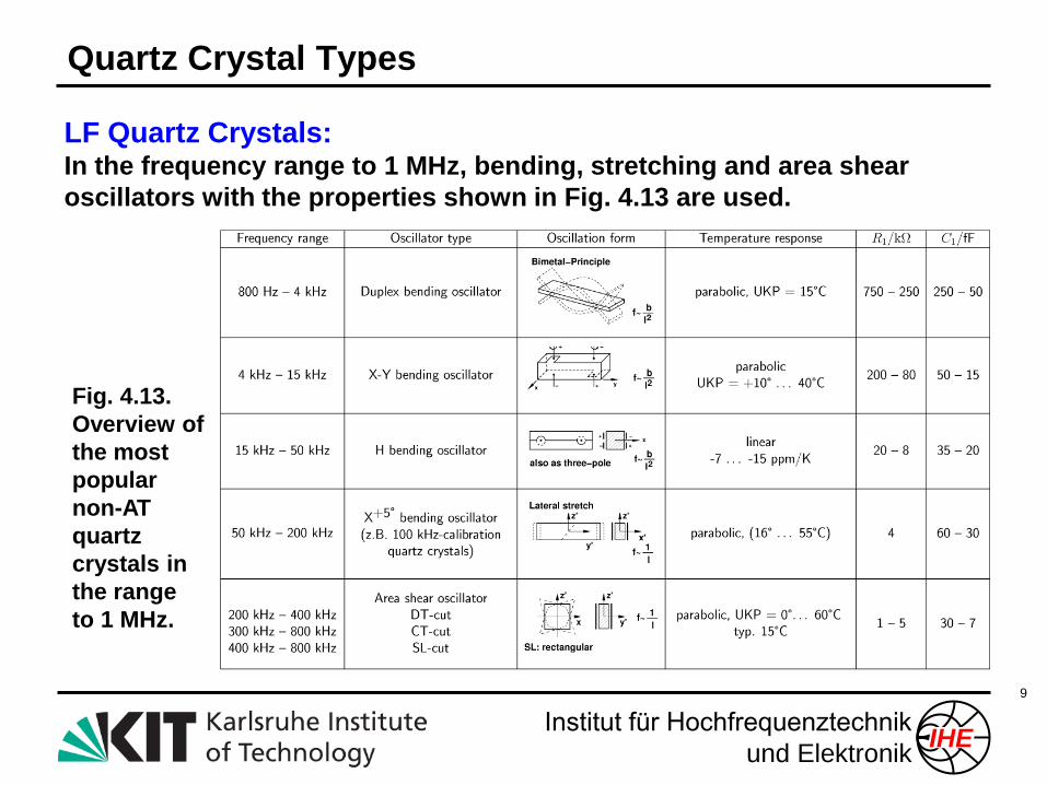
LF Quartz Crystals:In the frequency range to 1 MHz, bending, stretching and area shear
oscillators with the properties shown in Fig. 4.13 are used.
Fig. 4.13.
Overview of
the most
popular
non-AT
quartz
crystals in
the range
to 1 MHz.
Quartz Crystal Types
Institut für Hochfrequenztechnik
und ElektronikIHE
10
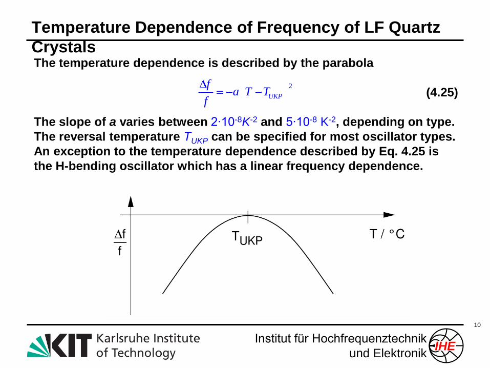
The temperature dependence is described by the parabola
(4.25)
The slope of a varies between 2∙10-8K-2 and 5∙10-8 K-2, depending on type.
The reversal temperature TUKP can be specified for most oscillator types.
An exception to the temperature dependence described by Eq. 4.25 is
the H-bending oscillator which has a linear frequency dependence.
2
UKP
fa T T
f
Temperature Dependence of Frequency of LF Quartz
Crystals
Institut für Hochfrequenztechnik
und ElektronikIHE
11
At high frequencies quartz crystals with an AT cut are utilised. AT quartz
crystals are thickness shear quartz resonators with a fundamental
frequency range of between about 750 kHz and 25 MHz. The dependence
of the relative frequency change on the temperature can be well
approximated by a cubic parabola
(4.26)
where a1 = 84∙10-9 Δθ K-1, where Δθ is in radian minutes, and a3 = 10-10 K-3.
Δθ is the deviation from the so-called zero angle. It is the cutting angle Δθ
for which the turning tangent in the temperature dependence (curve (1) in
Fig. 4.15) is horizontal. TINV is the temperature at the turning point. Fig.
4.15 qualtitatively shows the relative frequency change for two different
cutting angles as a function of temperature.
Modern micromechnical etching techniques (inverted mesa) allow the
manufacturing of AT fundamental tone quartz oscillators with resonant
frequencies to 250 MHz.
3
1 3INV INV
fa T T a T T
f
AT Fundamental Tone Oscillator (I)

Institut für Hochfrequenztechnik
und ElektronikIHE
12
Fig. 4.15.
Relative frequency
change of AT quartz
crystals (qualitative) with
different cutting angles
relative to the
crystallographic axes.
Table 4.1. Substitute data of AT fundamental tone quartz crystals.
AT Fundamental Tone Oscillator (II)
Institut für Hochfrequenztechnik
und ElektronikIHE
13
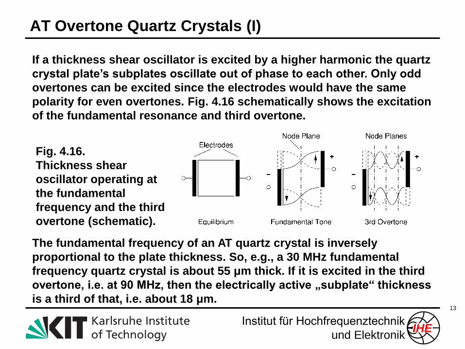
If a thickness shear oscillator is excited by a higher harmonic the quartz
crystal plate’s subplates oscillate out of phase to each other. Only odd
overtones can be excited since the electrodes would have the same
polarity for even overtones. Fig. 4.16 schematically shows the excitation
of the fundamental resonance and third overtone.
Fig. 4.16.
Thickness shear
oscillator operating at
the fundamental
frequency and the third
overtone (schematic).
The fundamental frequency of an AT quartz crystal is inversely
proportional to the plate thickness. So, e.g., a 30 MHz fundamental
frequency quartz crystal is about 55 μm thick. If it is excited in the third
overtone, i.e. at 90 MHz, then the electrically active „subplate“ thickness
is a third of that, i.e. about 18 μm.
AT Overtone Quartz Crystals (I)
Institut für Hochfrequenztechnik
und ElektronikIHE
14
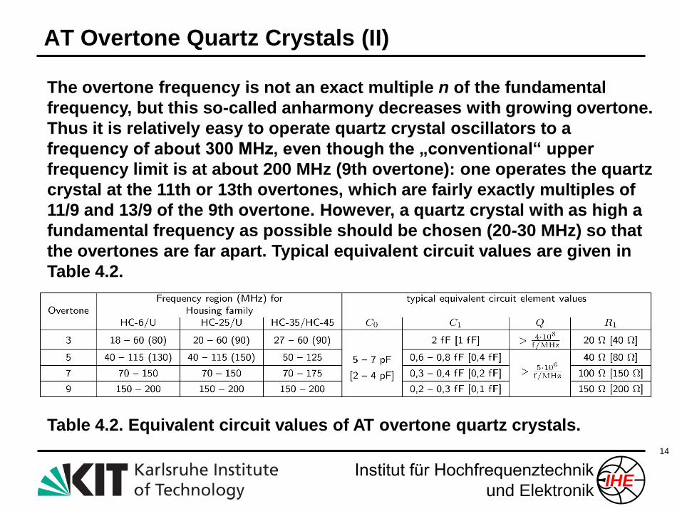
The overtone frequency is not an exact multiple n of the fundamental
frequency, but this so-called anharmony decreases with growing overtone.
Thus it is relatively easy to operate quartz crystal oscillators to a
frequency of about 300 MHz, even though the „conventional“ upper
frequency limit is at about 200 MHz (9th overtone): one operates the quartz
crystal at the 11th or 13th overtones, which are fairly exactly multiples of
11/9 and 13/9 of the 9th overtone. However, a quartz crystal with as high a
fundamental frequency as possible should be chosen (20-30 MHz) so that
the overtones are far apart. Typical equivalent circuit values are given in
Table 4.2.
Table 4.2. Equivalent circuit values of AT overtone quartz crystals.
AT Overtone Quartz Crystals (II)
Institut für Hochfrequenztechnik
und ElektronikIHE
15
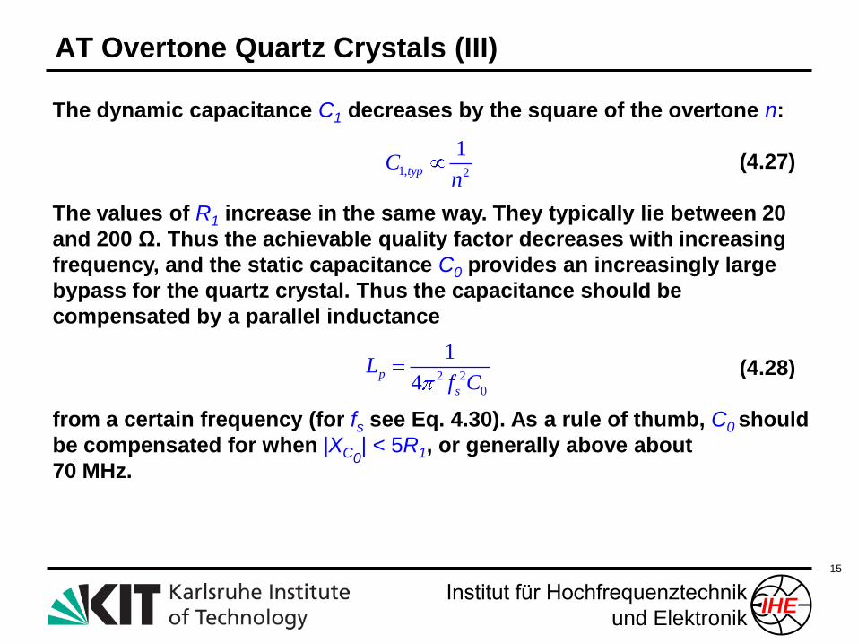
The dynamic capacitance C1 decreases by the square of the overtone n:
(4.27)
The values of R1 increase in the same way. They typically lie between 20
and 200 Ω. Thus the achievable quality factor decreases with increasing
frequency, and the static capacitance C0 provides an increasingly large
bypass for the quartz crystal. Thus the capacitance should be
compensated by a parallel inductance
(4.28)
from a certain frequency (for fs see Eq. 4.30). As a rule of thumb, C0 should
be compensated for when |XC0| < 5R1, or generally above about
70 MHz.
1, 2
1typC
n
2 2
0
1
4p
s
Lf C
AT Overtone Quartz Crystals (III)