lbr iiwa - cobotware · 6 / 81 issued: 23.05.2016 version: spez lbr iiwa v7 lbr iiwa manipulator...
TRANSCRIPT
Robots
LBR iiwa
LBR iiwa 7 R800, LBR iiwa 14 R820
Specification
KUKA Roboter GmbH
Issued: 23.05.2016
Version: Spez LBR iiwa V7
LBR iiwa
LBR iiwa
2 / 81 Issued: 23.05.2016 Version: Spez LBR iiwa V7
© Copyright 2016
KUKA Laboratories GmbH
Zugspitzstraße 140
D-86165 Augsburg
Germany
This documentation or excerpts therefrom may not be reproduced or disclosed to third parties without the express permission of the KUKA Laboratories GmbH.
Other functions not described in this documentation may be operable in the controller. The user has no claims to these functions, however, in the case of a replacement or service work.
We have checked the content of this documentation for conformity with the hardware and software described. Nevertheless, discrepancies cannot be precluded, for which reason we are not able to guarantee total conformity. The information in this documentation is checked on a regular basis, how-ever, and necessary corrections will be incorporated in the subsequent edition.
Subject to technical alterations without an effect on the function.
Translation of the original documentation
KIM-PS5-DOC
Publication: Pub Spez LBR iiwa en
Book structure: Spez LBR iiwa V4.1
Version: Spez LBR iiwa V7
3 / 81Issued: 23.05.2016 Version: Spez LBR iiwa V7
Contents
1 Introduction .................................................................................................. 5
1.1 Industrial robot documentation ................................................................................... 5
1.2 Representation of warnings and notes ...................................................................... 5
1.3 Terms used ................................................................................................................ 5
2 Purpose ........................................................................................................ 7
2.1 Target group .............................................................................................................. 7
2.2 Intended use .............................................................................................................. 7
3 Product description ..................................................................................... 9
3.1 Overview of the robot system .................................................................................... 9
3.2 Description of the LBR iiwa ........................................................................................ 9
4 Technical data .............................................................................................. 11
4.1 Technical data, overview ........................................................................................... 11
4.2 Technical data, LBR iiwa 7 R800 ............................................................................... 11
4.2.1 Basic data, LBR iiwa 7 R800 ................................................................................ 11
4.2.2 Axis data, LBR iiwa 7 R800 .................................................................................. 12
4.2.3 Payloads, LBR iiwa 7 R800 .................................................................................. 13
4.2.4 Foundation data, LBR iiwa 7 R800 ....................................................................... 15
4.3 Technical data, LBR iiwa 14 R820 ............................................................................. 17
4.3.1 Basic data, LBR iiwa 14 R820 .............................................................................. 17
4.3.2 Axis data, LBR iiwa 14 R820 ................................................................................ 17
4.3.3 Payloads, LBR iiwa 14 R820 ................................................................................ 19
4.3.4 Foundation data, LBR iiwa 14 R820 ..................................................................... 21
4.4 Plates and labels ........................................................................................................ 22
4.5 Stopping distances and times .................................................................................... 23
4.5.1 General information .............................................................................................. 23
4.5.2 Terms used ........................................................................................................... 24
4.5.3 Stopping distances and stopping times for LBR iiwa 7 R800 ............................... 26
4.5.3.1 Stopping distances and stopping times for STOP 0, axis 1 to axis 4 .............. 26
4.5.3.2 Stopping distances and stopping times for STOP 1, axis 1 ............................. 27
4.5.3.3 Stopping distances and stopping times for STOP 1, axis 2 ............................. 29
4.5.3.4 Stopping distances and stopping times for STOP 1, axis 3 ............................. 31
4.5.3.5 Stopping distances and stopping times for STOP 1, axis 4 ............................. 33
4.5.4 Stopping distances and stopping times for LBR iiwa 14 R820 ............................. 34
4.5.4.1 Stopping distances and stopping times for STOP 0, axis 1 to axis 4 .............. 35
4.5.4.2 Stopping distances and stopping times for STOP 1, axis 1 ............................. 36
4.5.4.3 Stopping distances and stopping times for STOP 1, axis 2 ............................. 38
4.5.4.4 Stopping distances and stopping times for STOP 1, axis 3 ............................. 40
4.5.4.5 Stopping distances and stopping times for STOP 1, axis 4 ............................. 42
5 Safety ............................................................................................................ 45
5.1 Legal framework ........................................................................................................ 45
5.1.1 Liability .................................................................................................................. 45
5.1.2 Intended use of the industrial robot ...................................................................... 45
5.1.3 EC declaration of conformity and declaration of incorporation ............................. 46
5.2 Safety functions ......................................................................................................... 46
Contents
4 / 81 Issued: 23.05.2016 Version: Spez LBR iiwa V7
LBR iiwa
5.2.1 Terms used .......................................................................................................... 47
5.2.2 Personnel ............................................................................................................. 48
5.2.3 Workspace, safety zone and danger zone ........................................................... 49
5.2.4 Safety-oriented functions ...................................................................................... 50
5.2.4.1 EMERGENCY STOP device ........................................................................... 51
5.2.4.2 Enabling device ............................................................................................... 51
5.2.4.3 “Operator safety” signal ................................................................................... 52
5.2.4.4 External EMERGENCY STOP device ............................................................. 52
5.2.4.5 External safety stop 1 (path-maintaining) ....................................................... 52
5.2.4.6 External enabling device ................................................................................. 53
5.2.4.7 External safe operational stop ......................................................................... 53
5.2.5 Triggers for safety-oriented stop reactions ........................................................... 53
5.2.6 Non-safety-oriented functions ............................................................................... 54
5.2.6.1 Mode selection ................................................................................................ 54
5.2.6.2 Software limit switches .................................................................................... 55
5.3 Additional protective equipment ................................................................................ 56
5.3.1 Jog mode .............................................................................................................. 56
5.3.2 Labeling on the industrial robot ............................................................................ 56
5.3.3 External safeguards ............................................................................................. 56
5.4 Safety measures ........................................................................................................ 57
5.4.1 General safety measures ..................................................................................... 57
5.4.2 Transportation ...................................................................................................... 58
5.4.3 Start-up and recommissioning .............................................................................. 58
5.4.4 Manual mode ........................................................................................................ 60
5.4.5 Automatic mode ................................................................................................... 61
5.4.6 Maintenance and repair ........................................................................................ 61
5.4.7 Decommissioning, storage and disposal .............................................................. 62
5.4.8 Safety measures for “single point of control” ........................................................ 62
5.5 Applied norms and directives .................................................................................... 63
6 Planning ........................................................................................................ 65
6.1 Mounting variant ........................................................................................................ 65
6.1.1 Machine frame mounting with centering ............................................................... 65
6.2 Connecting cables and interfaces ............................................................................. 66
7 Transportation ............................................................................................. 69
7.1 Transportation ........................................................................................................... 69
7.1.1 Transportation with transport packaging .............................................................. 69
7.1.2 Transportation with transport box (optional) ......................................................... 70
8 KUKA Service ............................................................................................... 71
8.1 Requesting support ................................................................................................... 71
8.2 KUKA Customer Support ........................................................................................... 71
Index ............................................................................................................. 79
5 / 81Issued: 23.05.2016 Version: Spez LBR iiwa V7
1 Introduction
1 Introduction
1.1 Industrial robot documentation
The industrial robot documentation consists of the following parts:
Documentation for the manipulator
Documentation for the robot controller
Operating and programming instructions for the System Software
Instructions for options and accessories
Parts catalog on storage medium
Each of these sets of instructions is a separate document.
1.2 Representation of warnings and notes
Safety These warnings are relevant to safety and must be observed.
This warning draws attention to procedures which serve to prevent or remedy emergencies or malfunctions:
Notices These notices serve to make your work easier or contain references to further information.
1.3 Terms used
t
t
These warnings mean that it is certain or highly probable that death or severe injuries will occur, if no precautions
are taken.
These warnings mean that death or severe injuries may occur, if no precautions are taken.
These warnings mean that minor injuries may occur, if no precautions are taken.
These warnings mean that damage to property may oc-cur, if no precautions are taken.
These warnings contain references to safety-relevant information or general safety measures. These warnings do not refer to individual hazards or individual pre-
cautionary measures.
Procedures marked with this warning must be followed exactly.
Tip to make your work easier or reference to further information.
Term Description
LBR iiwa Lightweight robot intelligent industrial work assistant

6 / 81 Issued: 23.05.2016 Version: Spez LBR iiwa V7
LBR iiwa
Manipulator The robot arm and the associated electrical installations
KCP
smartPAD
The KCP (KUKA Control Panel) teach pendant has all the operator control and display functions required for operating and programming the industrial robot.
The KCP variant for the KUKA Sunrise Cabinet is called KUKA smartPAD. The general term “KCP”, however, is generally used in this docu-mentation.
Term Description
7 / 81Issued: 23.05.2016 Version: Spez LBR iiwa V7
2 Purpose
2 Purpose
2.1 Target group
This documentation is aimed at users with the following knowledge and skills:
Advanced knowledge of mechanical engineering
Advanced knowledge of electrical and electronic systems
Knowledge of the robot controller system
2.2 Intended use
Use The industrial robot is intended for handling tools and fixtures, or for process-ing or transferring components or products. Use is only permitted under the specified environmental conditions.
Misuse Any use or application deviating from the intended use is deemed to be imper-missible misuse; examples of such misuse include:
Transportation of persons and animals
Use as a climbing aid
Operation outside the permissible operating parameters
Use in potentially explosive environments
Outdoor operation
Leaning on the robot arm
Underground operation
2
s
For optimal use of our products, we recommend that our customers take part in a course of training at KUKA College. Information about the training program can be found at www.kuka.com or can be ob-
tained directly from our subsidiaries.
Changing the structure of the manipulator, e.g. by drilling holes, etc., can result in damage to the components. This
is considered improper use and leads to loss of guarantee and liability enti-tlements.

8 / 81 Issued: 23.05.2016 Version: Spez LBR iiwa V7
LBR iiwa
9 / 81Issued: 23.05.2016 Version: Spez LBR iiwa V7
3 Product description
3 Product description
3.1 Overview of the robot system
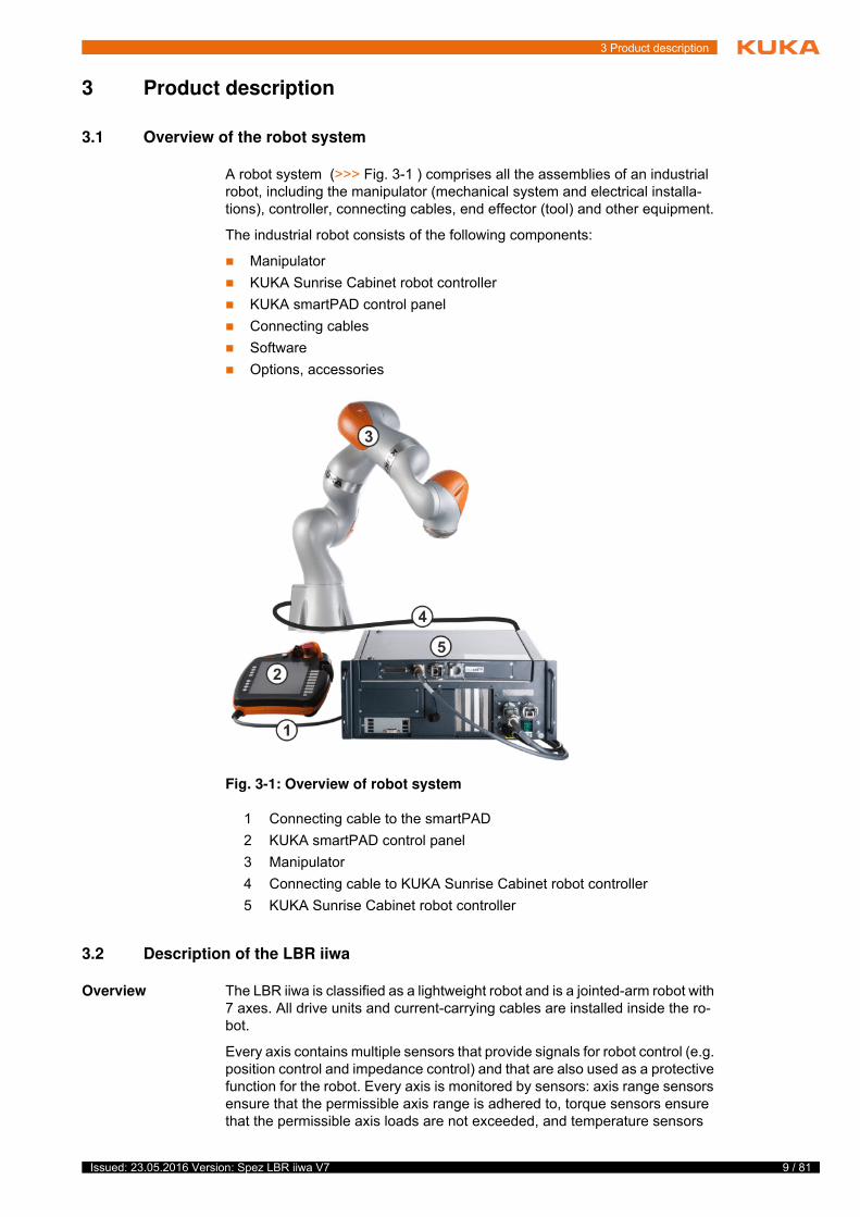
A robot system (>>> Fig. 3-1 ) comprises all the assemblies of an industrial robot, including the manipulator (mechanical system and electrical installa-tions), controller, connecting cables, end effector (tool) and other equipment.
The industrial robot consists of the following components:
Manipulator
KUKA Sunrise Cabinet robot controller
KUKA smartPAD control panel
Connecting cables
Software
Options, accessories
3.2 Description of the LBR iiwa
Overview The LBR iiwa is classified as a lightweight robot and is a jointed-arm robot with 7 axes. All drive units and current-carrying cables are installed inside the ro-bot.
Every axis contains multiple sensors that provide signals for robot control (e.g. position control and impedance control) and that are also used as a protective function for the robot. Every axis is monitored by sensors: axis range sensors ensure that the permissible axis range is adhered to, torque sensors ensure that the permissible axis loads are not exceeded, and temperature sensors
t
s
Fig. 3-1: Overview of robot system
1 Connecting cable to the smartPAD
2 KUKA smartPAD control panel
3 Manipulator
4 Connecting cable to KUKA Sunrise Cabinet robot controller
5 KUKA Sunrise Cabinet robot controller
10 / 81 Issued: 23.05.2016 Version: Spez LBR iiwa V7
LBR iiwa
monitor the thermal limit values of the electronics. In the case of an unfavor-able combination of permanently high demand on robot power and external temperature influences, the LBR is protected by this temperature monitoring which switches it off if the thermal limit values are exceeded. Following a cool-ing time, the LBR can be restarted with no need for additional measures. Tech-nical Support is available to answer any questions.
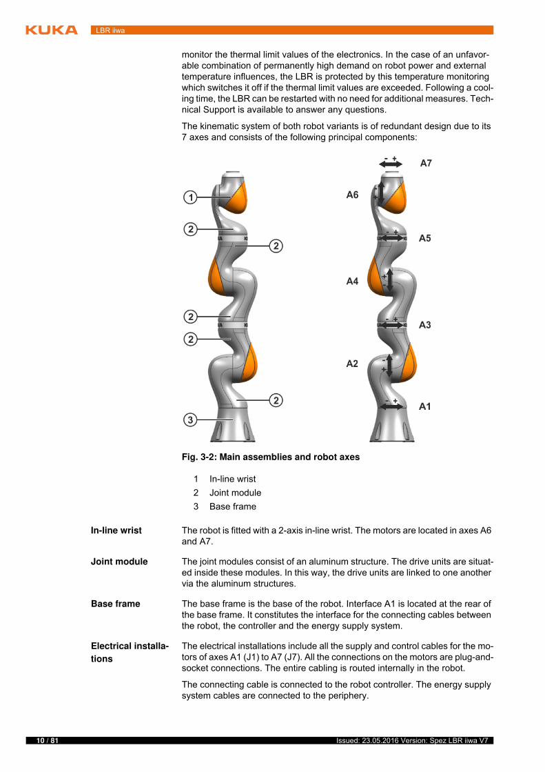
The kinematic system of both robot variants is of redundant design due to its 7 axes and consists of the following principal components:
In-line wrist The robot is fitted with a 2-axis in-line wrist. The motors are located in axes A6 and A7.
Joint module The joint modules consist of an aluminum structure. The drive units are situat-ed inside these modules. In this way, the drive units are linked to one another via the aluminum structures.
Base frame The base frame is the base of the robot. Interface A1 is located at the rear of the base frame. It constitutes the interface for the connecting cables between the robot, the controller and the energy supply system.
Electrical installa-
tions
The electrical installations include all the supply and control cables for the mo-tors of axes A1 (J1) to A7 (J7). All the connections on the motors are plug-and-socket connections. The entire cabling is routed internally in the robot.
The connecting cable is connected to the robot controller. The energy supply system cables are connected to the periphery.
Fig. 3-2: Main assemblies and robot axes
1 In-line wrist
2 Joint module
3 Base frame
11 / 81Issued: 23.05.2016 Version: Spez LBR iiwa V7
4 Technical data
4 Technical data
4.1 Technical data, overview
The technical data for the individual robot types can be found in the following sections:
4.2 Technical data, LBR iiwa 7 R800
4.2.1 Basic data, LBR iiwa 7 R800
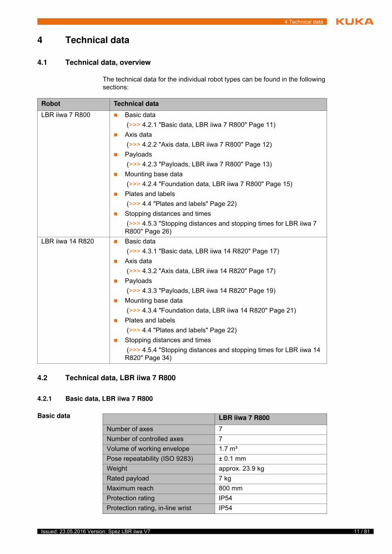
Basic data
4
T
t
Robot Technical data
LBR iiwa 7 R800 Basic data
(>>> 4.2.1 "Basic data, LBR iiwa 7 R800" Page 11)
Axis data
(>>> 4.2.2 "Axis data, LBR iiwa 7 R800" Page 12)
Payloads
(>>> 4.2.3 "Payloads, LBR iiwa 7 R800" Page 13)
Mounting base data
(>>> 4.2.4 "Foundation data, LBR iiwa 7 R800" Page 15)
Plates and labels
(>>> 4.4 "Plates and labels" Page 22)
Stopping distances and times
(>>> 4.5.3 "Stopping distances and stopping times for LBR iiwa 7 R800" Page 26)
LBR iiwa 14 R820 Basic data
(>>> 4.3.1 "Basic data, LBR iiwa 14 R820" Page 17)
Axis data
(>>> 4.3.2 "Axis data, LBR iiwa 14 R820" Page 17)
Payloads
(>>> 4.3.3 "Payloads, LBR iiwa 14 R820" Page 19)
Mounting base data
(>>> 4.3.4 "Foundation data, LBR iiwa 14 R820" Page 21)
Plates and labels
(>>> 4.4 "Plates and labels" Page 22)
Stopping distances and times
(>>> 4.5.4 "Stopping distances and stopping times for LBR iiwa 14 R820" Page 34)
LBR iiwa 7 R800
Number of axes 7
Number of controlled axes 7
Volume of working envelope 1.7 m³
Pose repeatability (ISO 9283) ± 0.1 mm
Weight approx. 23.9 kg
Rated payload 7 kg
Maximum reach 800 mm
Protection rating IP54
Protection rating, in-line wrist IP54
12 / 81 Issued: 23.05.2016 Version: Spez LBR iiwa V7
LBR iiwa
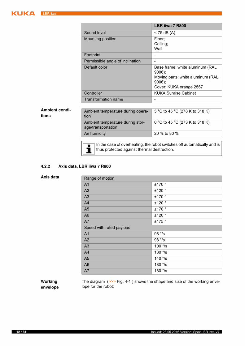
Ambient condi-
tions
4.2.2 Axis data, LBR iiwa 7 R800
Axis data
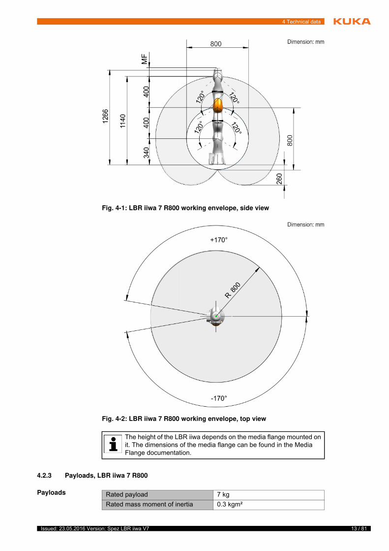
Working
envelope
The diagram (>>> Fig. 4-1 ) shows the shape and size of the working enve-lope for the robot:
Sound level < 75 dB (A)
Mounting position Floor;Ceiling;Wall
Footprint -
Permissible angle of inclination -
Default color Base frame: white aluminum (RAL 9006);Moving parts: white aluminum (RAL 9006);Cover: KUKA orange 2567
Controller KUKA Sunrise Cabinet
Transformation name -
LBR iiwa 7 R800
Ambient temperature during opera-tion
5 °C to 45 °C (278 K to 318 K)
Ambient temperature during stor-age/transportation
0 °C to 45 °C (273 K to 318 K)
Air humidity 20 % to 80 %
In the case of overheating, the robot switches off automatically and is thus protected against thermal destruction.
Range of motion
A1 ±170 °
A2 ±120 °
A3 ±170 °
A4 ±120 °
A5 ±170 °
A6 ±120 °
A7 ±175 °
Speed with rated payload
A1 98 °/s
A2 98 °/s
A3 100 °/s
A4 130 °/s
A5 140 °/s
A6 180 °/s
A7 180 °/s
13 / 81Issued: 23.05.2016 Version: Spez LBR iiwa V7
4 Technical data
4.2.3 Payloads, LBR iiwa 7 R800
Payloads
Fig. 4-1: LBR iiwa 7 R800 working envelope, side view
Fig. 4-2: LBR iiwa 7 R800 working envelope, top view
The height of the LBR iiwa depends on the media flange mounted on it. The dimensions of the media flange can be found in the Media Flange documentation.
Rated payload 7 kg
Rated mass moment of inertia 0.3 kgm²
14 / 81 Issued: 23.05.2016 Version: Spez LBR iiwa V7
LBR iiwa
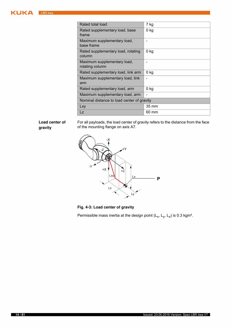
Load center of
gravity
For all payloads, the load center of gravity refers to the distance from the face of the mounting flange on axis A7.
Permissible mass inertia at the design point (Lx, Ly, Lz) is 0.3 kgm².
Rated total load 7 kg
Rated supplementary load, base frame
0 kg
Maximum supplementary load, base frame
-
Rated supplementary load, rotating column
0 kg
Maximum supplementary load, rotating column
-
Rated supplementary load, link arm 0 kg
Maximum supplementary load, link arm
-
Rated supplementary load, arm 0 kg
Maximum supplementary load, arm -
Nominal distance to load center of gravity
Lxy 35 mm
Lz 60 mm
Fig. 4-3: Load center of gravity
15 / 81Issued: 23.05.2016 Version: Spez LBR iiwa V7
4 Technical data
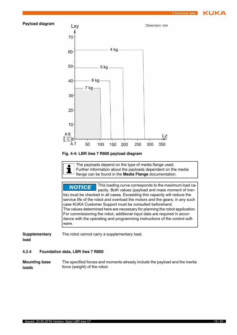
Payload diagram
Supplementary
load
The robot cannot carry a supplementary load.
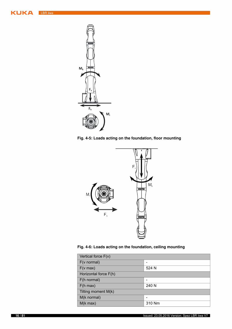
4.2.4 Foundation data, LBR iiwa 7 R800
Mounting base
loads
The specified forces and moments already include the payload and the inertia force (weight) of the robot.
Fig. 4-4: LBR iiwa 7 R800 payload diagram
The payloads depend on the type of media flange used.Further information about the payloads dependent on the media flange can be found in the Media Flange documentation.
This loading curve corresponds to the maximum load ca-pacity. Both values (payload and mass moment of iner-
tia) must be checked in all cases. Exceeding this capacity will reduce the service life of the robot and overload the motors and the gears; in any such case KUKA Customer Support must be consulted beforehand.The values determined here are necessary for planning the robot application. For commissioning the robot, additional input data are required in accor-dance with the operating and programming instructions of the control soft-ware.
16 / 81 Issued: 23.05.2016 Version: Spez LBR iiwa V7
LBR iiwa
Fig. 4-5: Loads acting on the foundation, floor mounting
Fig. 4-6: Loads acting on the foundation, ceiling mounting
Vertical force F(v)
F(v normal) -
F(v max) 524 N
Horizontal force F(h)
F(h normal) -
F(h max) 240 N
Tilting moment M(k)
M(k normal) -
M(k max) 310 Nm
17 / 81Issued: 23.05.2016 Version: Spez LBR iiwa V7
4 Technical data
4.3 Technical data, LBR iiwa 14 R820
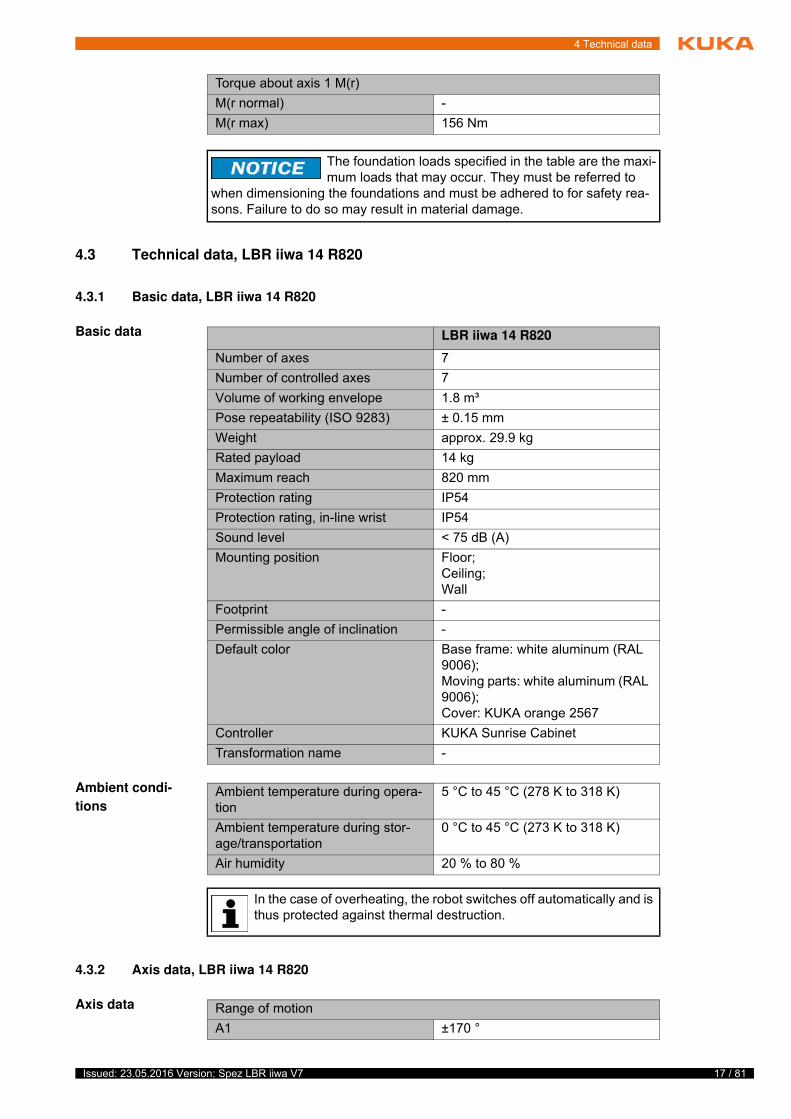
4.3.1 Basic data, LBR iiwa 14 R820
Basic data
Ambient condi-
tions
4.3.2 Axis data, LBR iiwa 14 R820
Axis data
Torque about axis 1 M(r)
M(r normal) -
M(r max) 156 Nm
The foundation loads specified in the table are the maxi-mum loads that may occur. They must be referred to
when dimensioning the foundations and must be adhered to for safety rea-sons. Failure to do so may result in material damage.
LBR iiwa 14 R820
Number of axes 7
Number of controlled axes 7
Volume of working envelope 1.8 m³
Pose repeatability (ISO 9283) ± 0.15 mm
Weight approx. 29.9 kg
Rated payload 14 kg
Maximum reach 820 mm
Protection rating IP54
Protection rating, in-line wrist IP54
Sound level < 75 dB (A)
Mounting position Floor;Ceiling;Wall
Footprint -
Permissible angle of inclination -
Default color Base frame: white aluminum (RAL 9006);Moving parts: white aluminum (RAL 9006);Cover: KUKA orange 2567
Controller KUKA Sunrise Cabinet
Transformation name -
Ambient temperature during opera-tion
5 °C to 45 °C (278 K to 318 K)
Ambient temperature during stor-age/transportation
0 °C to 45 °C (273 K to 318 K)
Air humidity 20 % to 80 %
In the case of overheating, the robot switches off automatically and is thus protected against thermal destruction.
Range of motion
A1 ±170 °
18 / 81 Issued: 23.05.2016 Version: Spez LBR iiwa V7
LBR iiwa
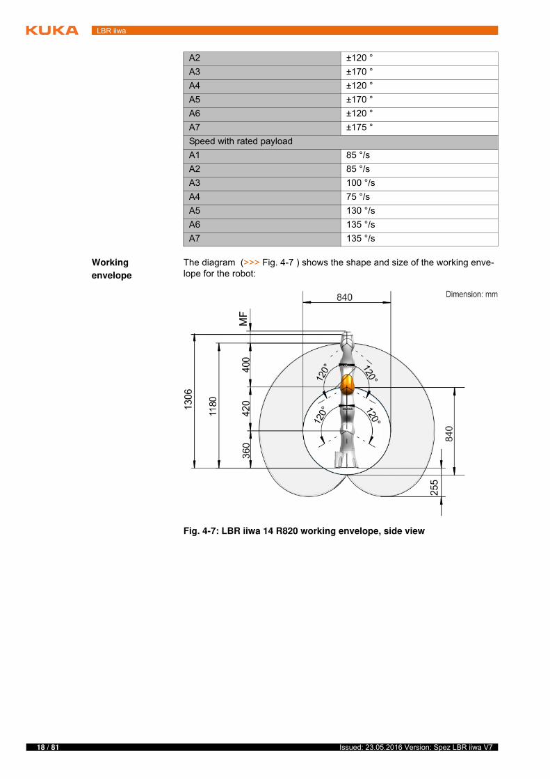
Working
envelope
The diagram (>>> Fig. 4-7 ) shows the shape and size of the working enve-lope for the robot:
A2 ±120 °
A3 ±170 °
A4 ±120 °
A5 ±170 °
A6 ±120 °
A7 ±175 °
Speed with rated payload
A1 85 °/s
A2 85 °/s
A3 100 °/s
A4 75 °/s
A5 130 °/s
A6 135 °/s
A7 135 °/s
Fig. 4-7: LBR iiwa 14 R820 working envelope, side view
19 / 81Issued: 23.05.2016 Version: Spez LBR iiwa V7
4 Technical data
4.3.3 Payloads, LBR iiwa 14 R820
Payloads
Load center of
gravity
For all payloads, the load center of gravity refers to the distance from the face of the mounting flange on axis A7.
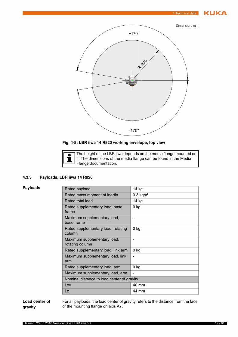
Fig. 4-8: LBR iiwa 14 R820 working envelope, top view
The height of the LBR iiwa depends on the media flange mounted on it. The dimensions of the media flange can be found in the Media Flange documentation.
Rated payload 14 kg
Rated mass moment of inertia 0.3 kgm²
Rated total load 14 kg
Rated supplementary load, base frame
0 kg
Maximum supplementary load, base frame
-
Rated supplementary load, rotating column
0 kg
Maximum supplementary load, rotating column
-
Rated supplementary load, link arm 0 kg
Maximum supplementary load, link arm
-
Rated supplementary load, arm 0 kg
Maximum supplementary load, arm -
Nominal distance to load center of gravity
Lxy 40 mm
Lz 44 mm
20 / 81 Issued: 23.05.2016 Version: Spez LBR iiwa V7
LBR iiwa
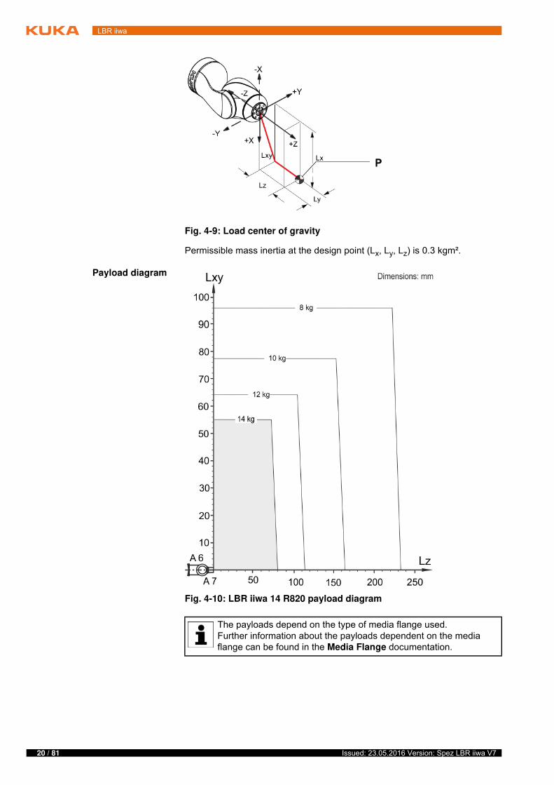
Permissible mass inertia at the design point (Lx, Ly, Lz) is 0.3 kgm².
Payload diagram
Fig. 4-9: Load center of gravity
Fig. 4-10: LBR iiwa 14 R820 payload diagram
The payloads depend on the type of media flange used.Further information about the payloads dependent on the media flange can be found in the Media Flange documentation.
21 / 81Issued: 23.05.2016 Version: Spez LBR iiwa V7
4 Technical data
Supplementary
load
The robot cannot carry a supplementary load.
4.3.4 Foundation data, LBR iiwa 14 R820
Mounting base
loads
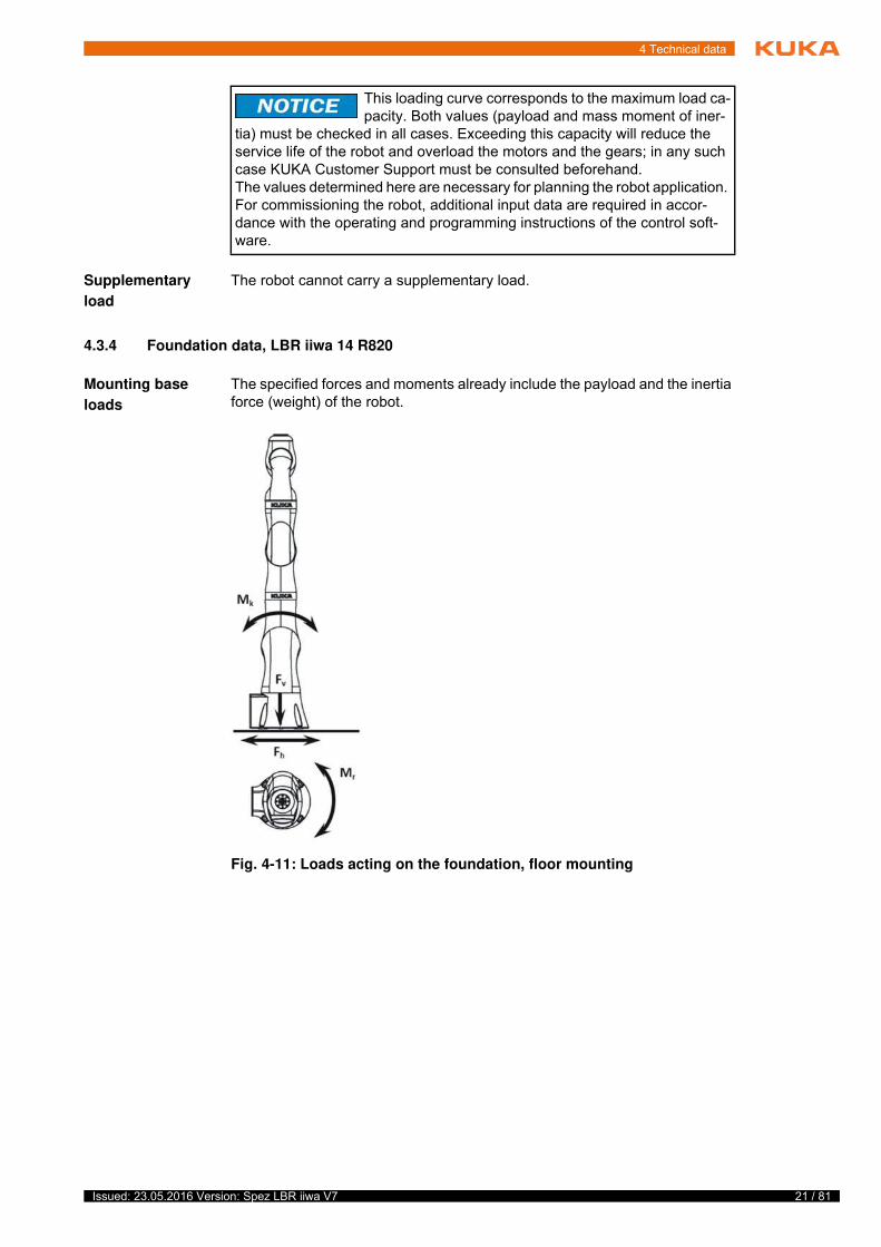
The specified forces and moments already include the payload and the inertia force (weight) of the robot.
This loading curve corresponds to the maximum load ca-pacity. Both values (payload and mass moment of iner-
tia) must be checked in all cases. Exceeding this capacity will reduce the service life of the robot and overload the motors and the gears; in any such case KUKA Customer Support must be consulted beforehand.The values determined here are necessary for planning the robot application. For commissioning the robot, additional input data are required in accor-dance with the operating and programming instructions of the control soft-ware.
Fig. 4-11: Loads acting on the foundation, floor mounting
22 / 81 Issued: 23.05.2016 Version: Spez LBR iiwa V7
LBR iiwa
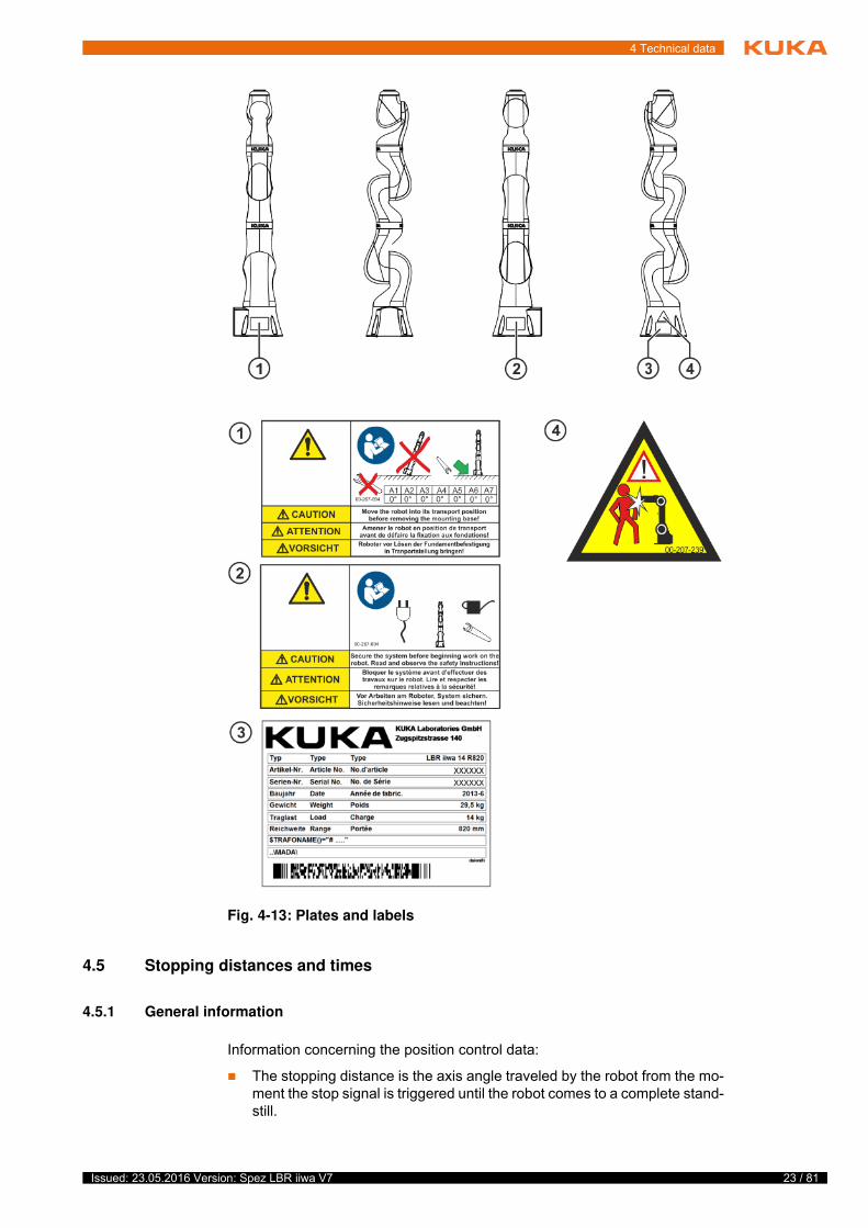
4.4 Plates and labels
Identification
plate
The following plates and labels are attached to the robot. They must not be re-moved or rendered illegible. Illegible plates and labels must be replaced.
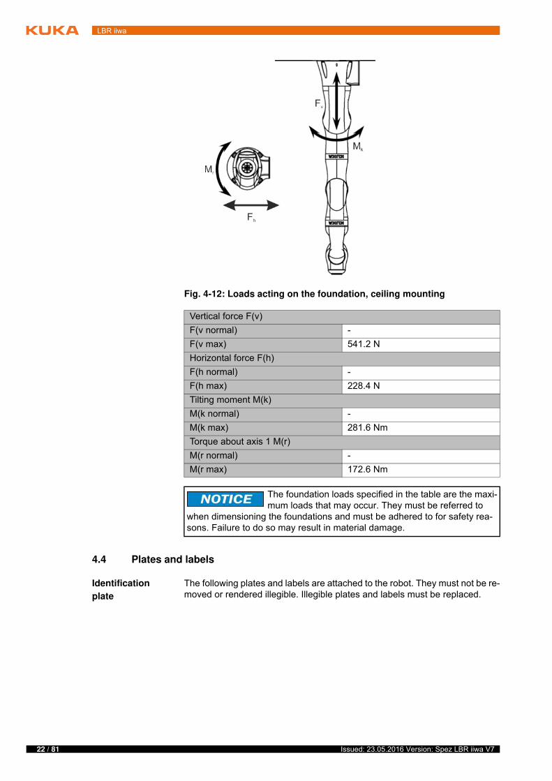
Fig. 4-12: Loads acting on the foundation, ceiling mounting
Vertical force F(v)
F(v normal) -
F(v max) 541.2 N
Horizontal force F(h)
F(h normal) -
F(h max) 228.4 N
Tilting moment M(k)
M(k normal) -
M(k max) 281.6 Nm
Torque about axis 1 M(r)
M(r normal) -
M(r max) 172.6 Nm
The foundation loads specified in the table are the maxi-mum loads that may occur. They must be referred to
when dimensioning the foundations and must be adhered to for safety rea-sons. Failure to do so may result in material damage.
23 / 81Issued: 23.05.2016 Version: Spez LBR iiwa V7
4 Technical data
4.5 Stopping distances and times
4.5.1 General information
Information concerning the position control data:
The stopping distance is the axis angle traveled by the robot from the mo-ment the stop signal is triggered until the robot comes to a complete stand-still.
Fig. 4-13: Plates and labels
24 / 81 Issued: 23.05.2016 Version: Spez LBR iiwa V7
LBR iiwa
The stopping time is the time that elapses from the moment the stop signal is triggered until the robot comes to a complete standstill.
The data are given for axes A1, A2, A3 and A4. These axes are the axes with the greatest deflection.
The data apply to single-axis motions. Superposed axis motions can result in longer stopping distances.
As reference, PTP motions with position control have been used without further parameterization (e.g. robot.move(ptp(Zielpose)) ).
Stopping distances and stopping times in accordance with DIN EN ISO 10218-1, Annex B.
Stop categories:
Stop category 0 » STOP 0
Stop category 1 » STOP 1 (path-maintaining)
according to IEC 60204-1
The values specified are guide values determined by means of tests and simulation. They are average values which conform to the requirements of DIN EN ISO 10218-1. The actual stopping distances and stopping times may differ due to internal and external influences on the braking torque. It is therefore advisable to determine the exact stopping distances and stop-ping times under the real conditions of the actual robot application.
Measuring technique
The stopping distances were measured using the robot-internal measur-ing technique with rated payloads.
The wear on the brakes varies depending on the operating mode, robot application and the number of STOP 0 stops triggered. It is therefore ad-visable to check the stopping distance at least once a year.
The stopping distances and stopping times can be determined, for example, by using safety monitoring to trigger axis-specific or Cartesian workspace monitoring of the safety stop that is to be checked and evaluating the corre-sponding measured data from the trace (by means of DataRecorder).
4.5.2 Terms used
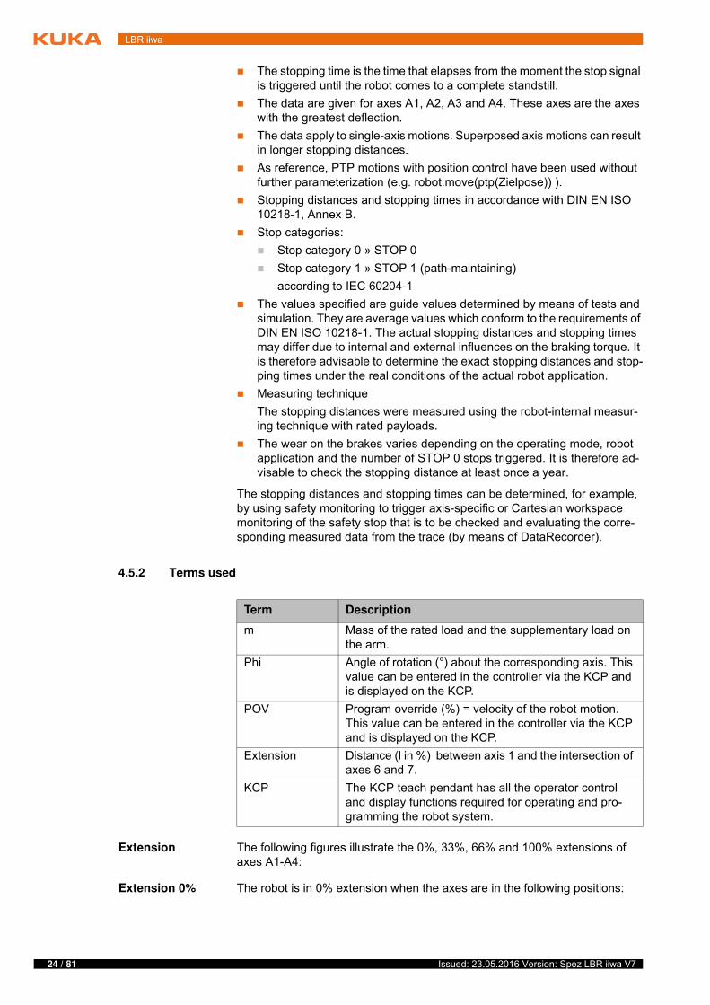
Extension The following figures illustrate the 0%, 33%, 66% and 100% extensions of axes A1-A4:
Extension 0% The robot is in 0% extension when the axes are in the following positions:
Term Description
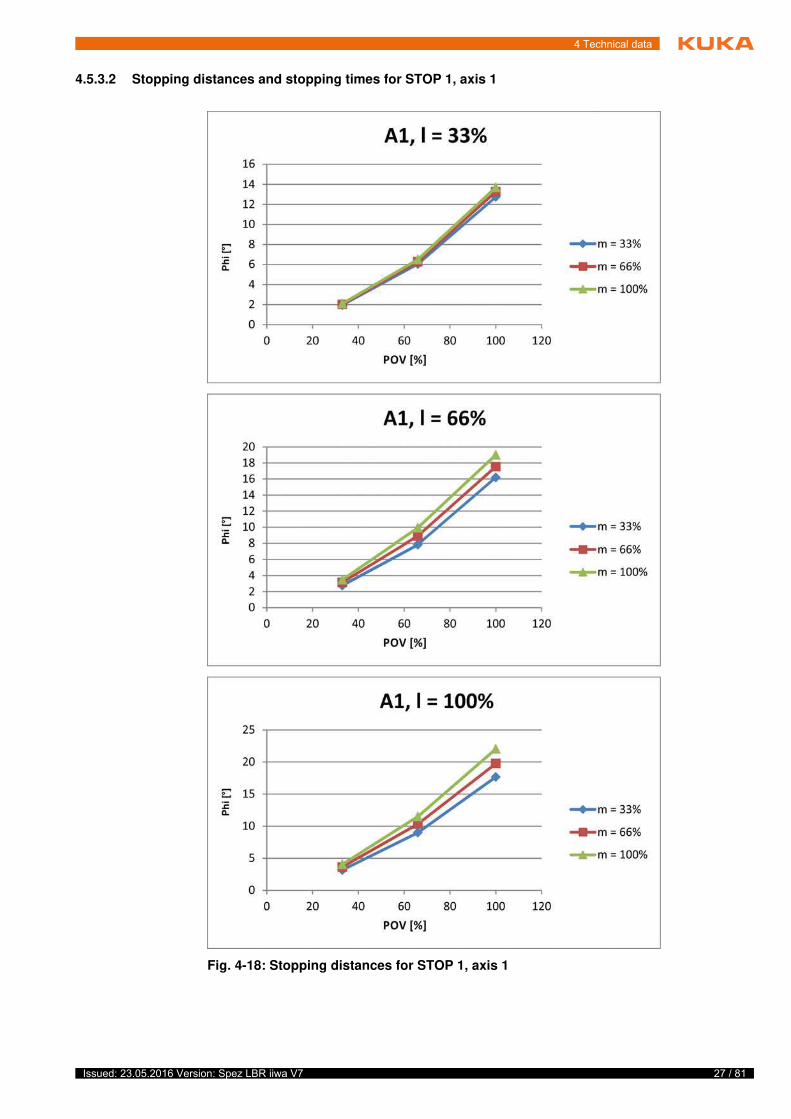
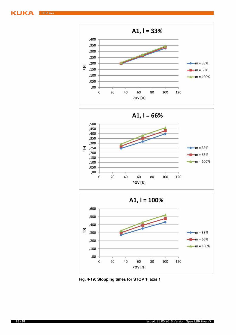
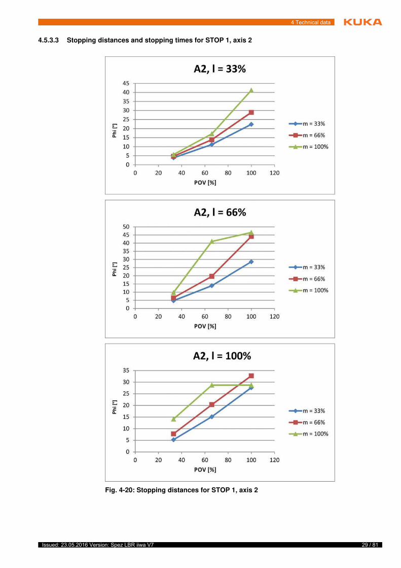
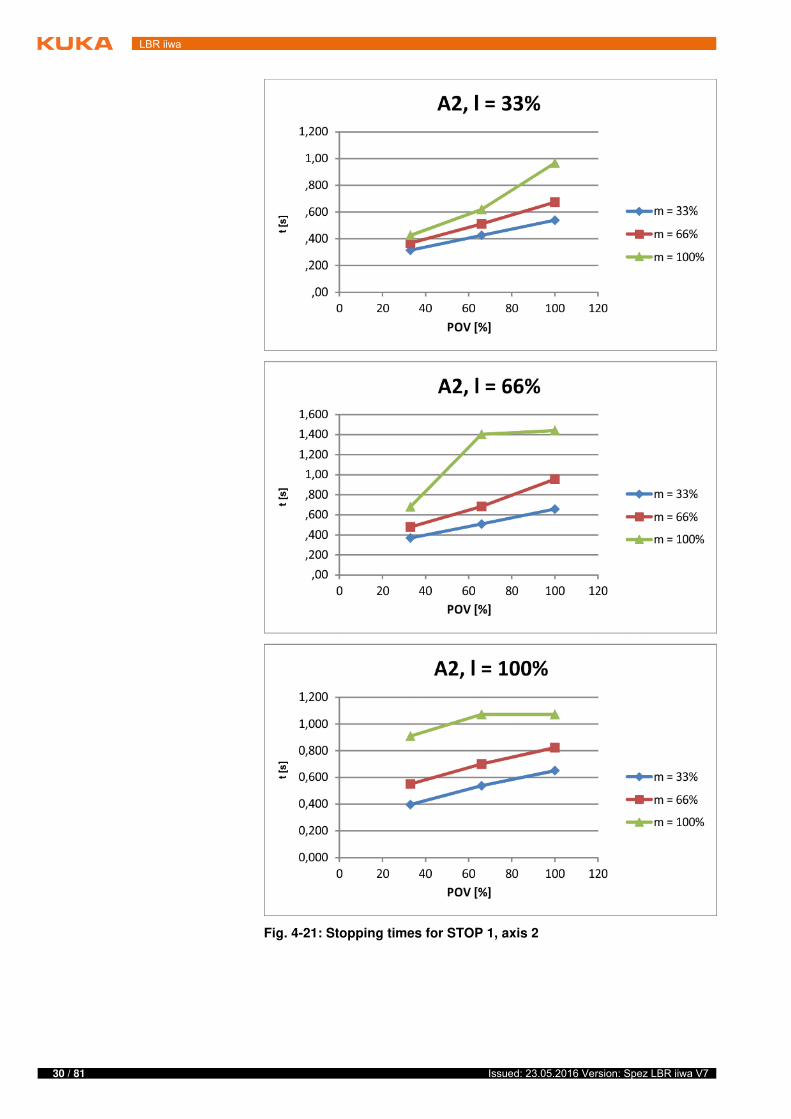
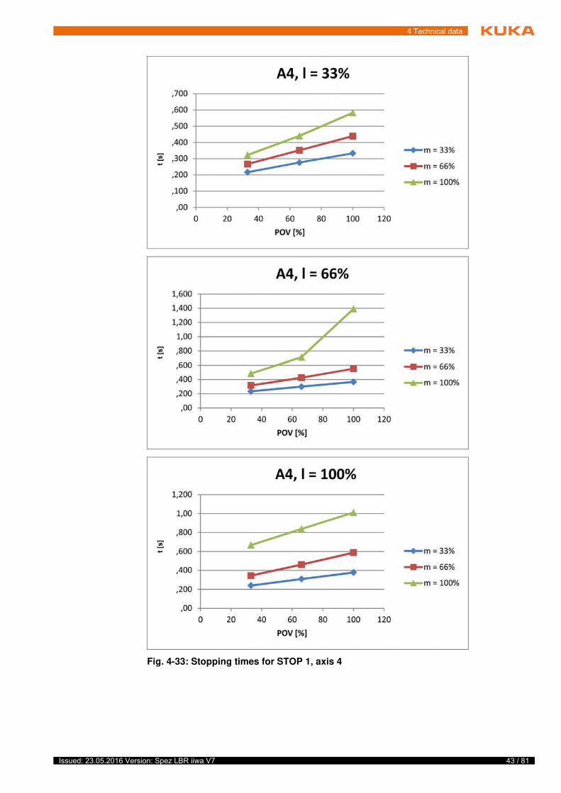
m Mass of the rated load and the supplementary load on the arm.
Phi Angle of rotation (°) about the corresponding axis. This value can be entered in the controller via the KCP and is displayed on the KCP.
POV Program override (%) = velocity of the robot motion. This value can be entered in the controller via the KCP and is displayed on the KCP.
Extension Distance (l in %) between axis 1 and the intersection of axes 6 and 7.
KCP The KCP teach pendant has all the operator control and display functions required for operating and pro-gramming the robot system.
25 / 81Issued: 23.05.2016 Version: Spez LBR iiwa V7
4 Technical data
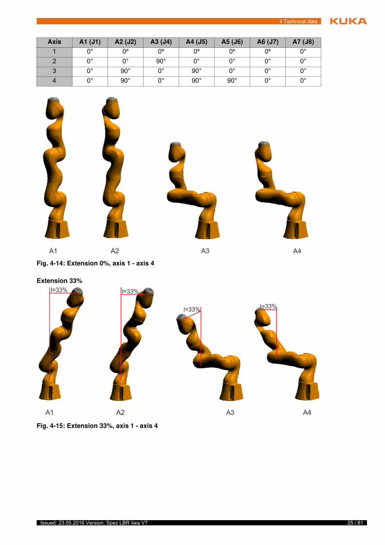
Extension 33%
Axis A1 (J1) A2 (J2) A3 (J4) A4 (J5) A5 (J6) A6 (J7) A7 (J8)
1 0° 0º 0º 0º 0º 0º 0°
2 0° 0° 90° 0° 0° 0° 0°
3 0° 90° 0° 90° 0° 0° 0°
4 0° 90° 0° 90° 90° 0° 0°
Fig. 4-14: Extension 0%, axis 1 - axis 4
Fig. 4-15: Extension 33%, axis 1 - axis 4
26 / 81 Issued: 23.05.2016 Version: Spez LBR iiwa V7
LBR iiwa
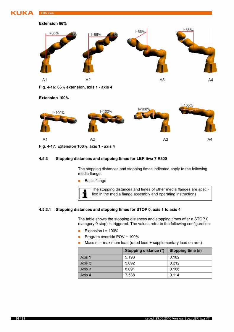
Extension 66%
Extension 100%
4.5.3 Stopping distances and stopping times for LBR iiwa 7 R800
The stopping distances and stopping times indicated apply to the following media flange:
Basic flange
4.5.3.1 Stopping distances and stopping times for STOP 0, axis 1 to axis 4
The table shows the stopping distances and stopping times after a STOP 0 (category 0 stop) is triggered. The values refer to the following configuration:
Extension l = 100%
Program override POV = 100%
Mass m = maximum load (rated load + supplementary load on arm)
Fig. 4-16: 66% extension, axis 1 - axis 4
Fig. 4-17: Extension 100%, axis 1 - axis 4
The stopping distances and times of other media flanges are speci-fied in the media flange assembly and operating instructions.
Stopping distance (°) Stopping time (s)
Axis 1 5.193 0.182
Axis 2 5.092 0.212
Axis 3 8.091 0.166
Axis 4 7.538 0.114
27 / 81Issued: 23.05.2016 Version: Spez LBR iiwa V7
4 Technical data
4.5.3.2 Stopping distances and stopping times for STOP 1, axis 1
Fig. 4-18: Stopping distances for STOP 1, axis 1
28 / 81 Issued: 23.05.2016 Version: Spez LBR iiwa V7
LBR iiwa
Fig. 4-19: Stopping times for STOP 1, axis 1
29 / 81Issued: 23.05.2016 Version: Spez LBR iiwa V7
4 Technical data
4.5.3.3 Stopping distances and stopping times for STOP 1, axis 2
Fig. 4-20: Stopping distances for STOP 1, axis 2
30 / 81 Issued: 23.05.2016 Version: Spez LBR iiwa V7
LBR iiwa
Fig. 4-21: Stopping times for STOP 1, axis 2
31 / 81Issued: 23.05.2016 Version: Spez LBR iiwa V7
4 Technical data
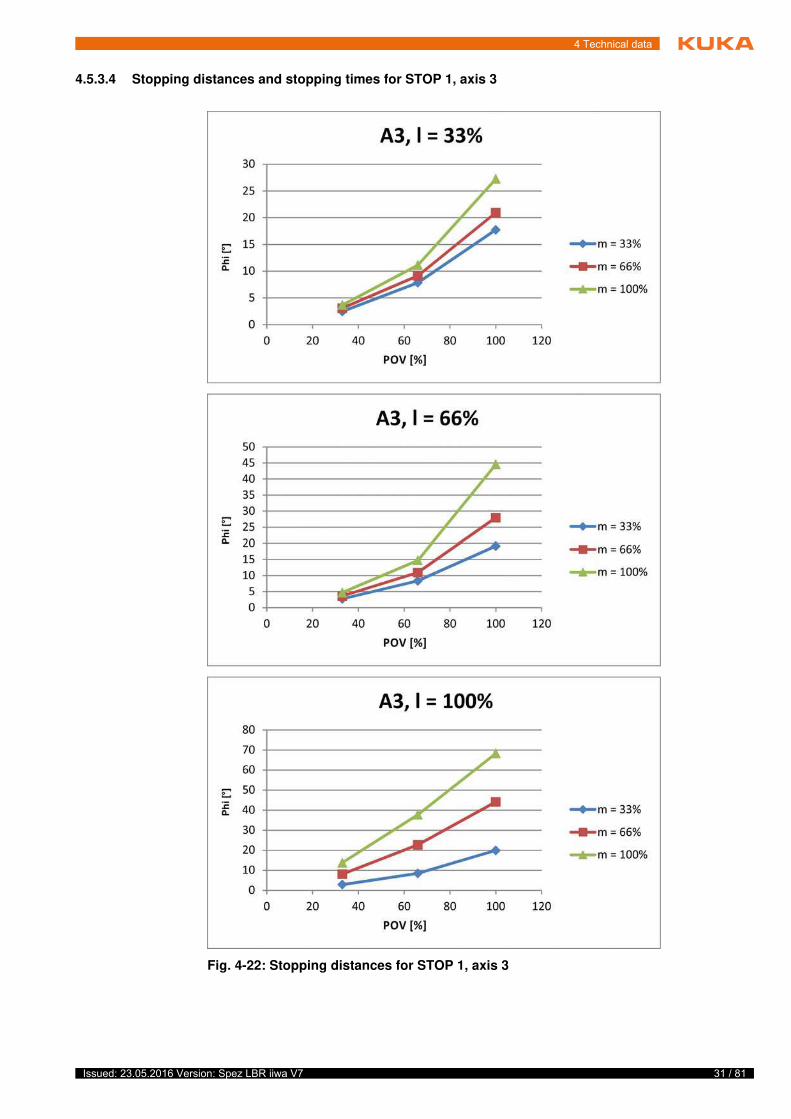
4.5.3.4 Stopping distances and stopping times for STOP 1, axis 3
Fig. 4-22: Stopping distances for STOP 1, axis 3
32 / 81 Issued: 23.05.2016 Version: Spez LBR iiwa V7
LBR iiwa
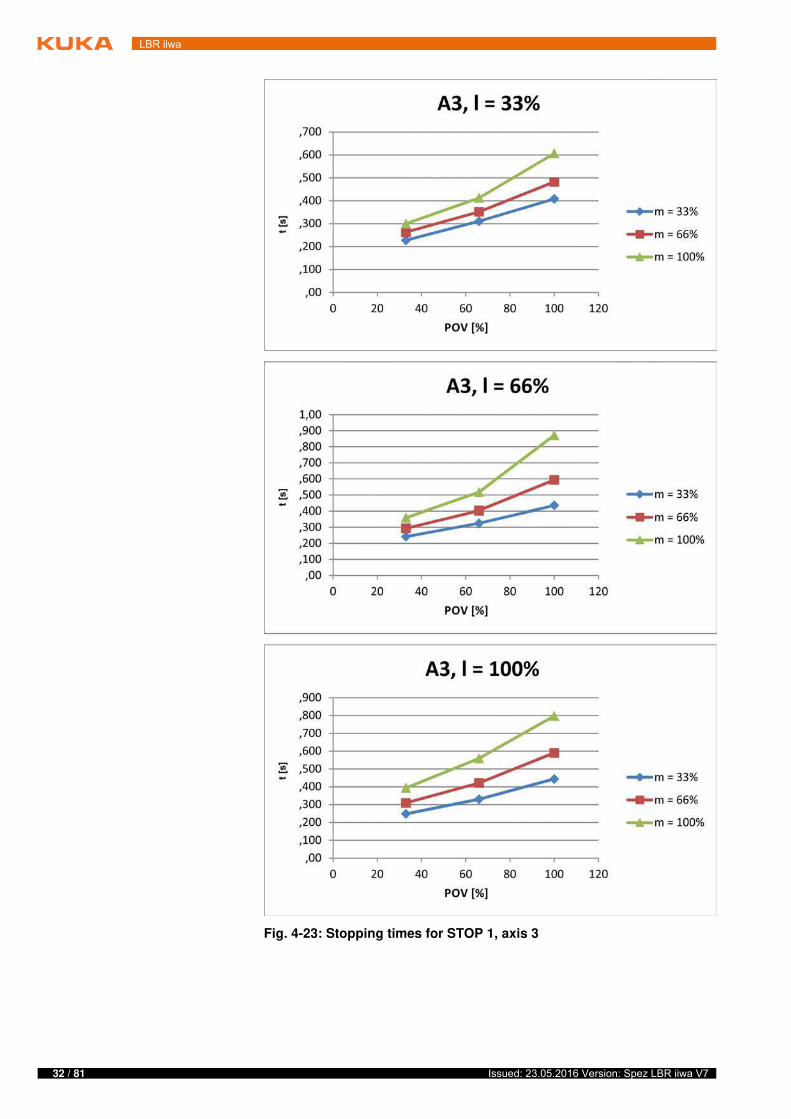
Fig. 4-23: Stopping times for STOP 1, axis 3
33 / 81Issued: 23.05.2016 Version: Spez LBR iiwa V7
4 Technical data
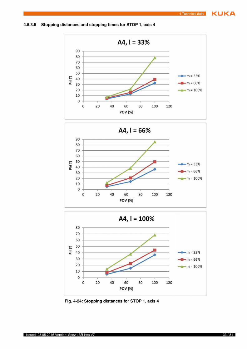
4.5.3.5 Stopping distances and stopping times for STOP 1, axis 4
Fig. 4-24: Stopping distances for STOP 1, axis 4
34 / 81 Issued: 23.05.2016 Version: Spez LBR iiwa V7
LBR iiwa
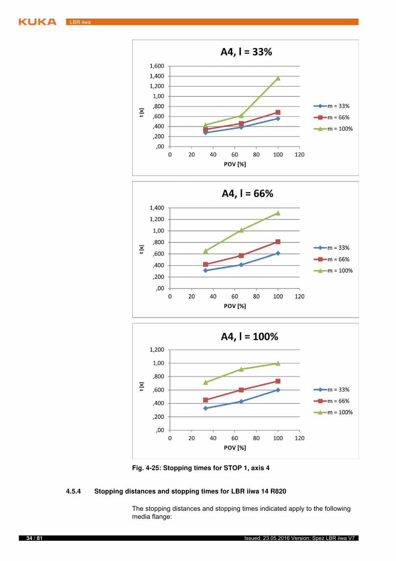
4.5.4 Stopping distances and stopping times for LBR iiwa 14 R820
The stopping distances and stopping times indicated apply to the following media flange:
Fig. 4-25: Stopping times for STOP 1, axis 4
35 / 81Issued: 23.05.2016 Version: Spez LBR iiwa V7
4 Technical data
Basic flange
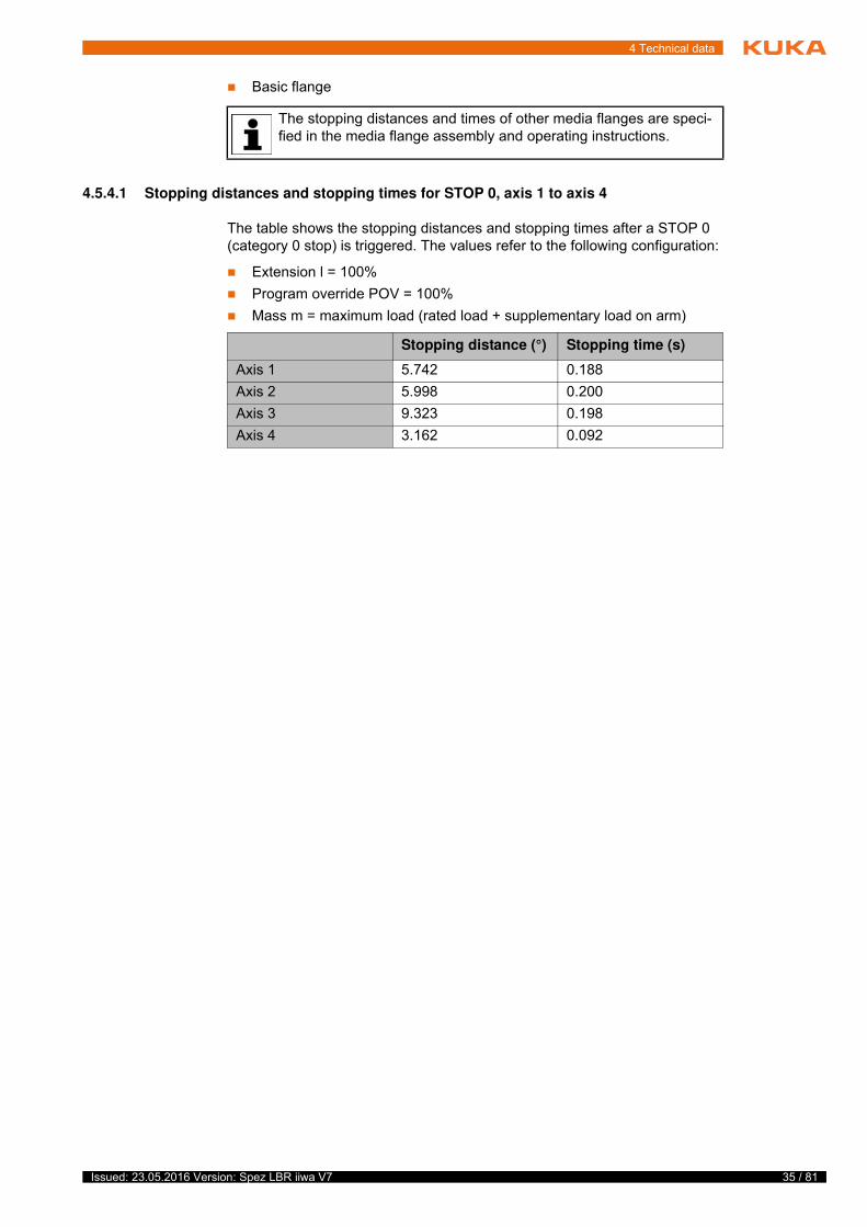
4.5.4.1 Stopping distances and stopping times for STOP 0, axis 1 to axis 4
The table shows the stopping distances and stopping times after a STOP 0 (category 0 stop) is triggered. The values refer to the following configuration:
Extension l = 100%
Program override POV = 100%
Mass m = maximum load (rated load + supplementary load on arm)
The stopping distances and times of other media flanges are speci-fied in the media flange assembly and operating instructions.
Stopping distance (°) Stopping time (s)
Axis 1 5.742 0.188
Axis 2 5.998 0.200
Axis 3 9.323 0.198
Axis 4 3.162 0.092
36 / 81 Issued: 23.05.2016 Version: Spez LBR iiwa V7
LBR iiwa
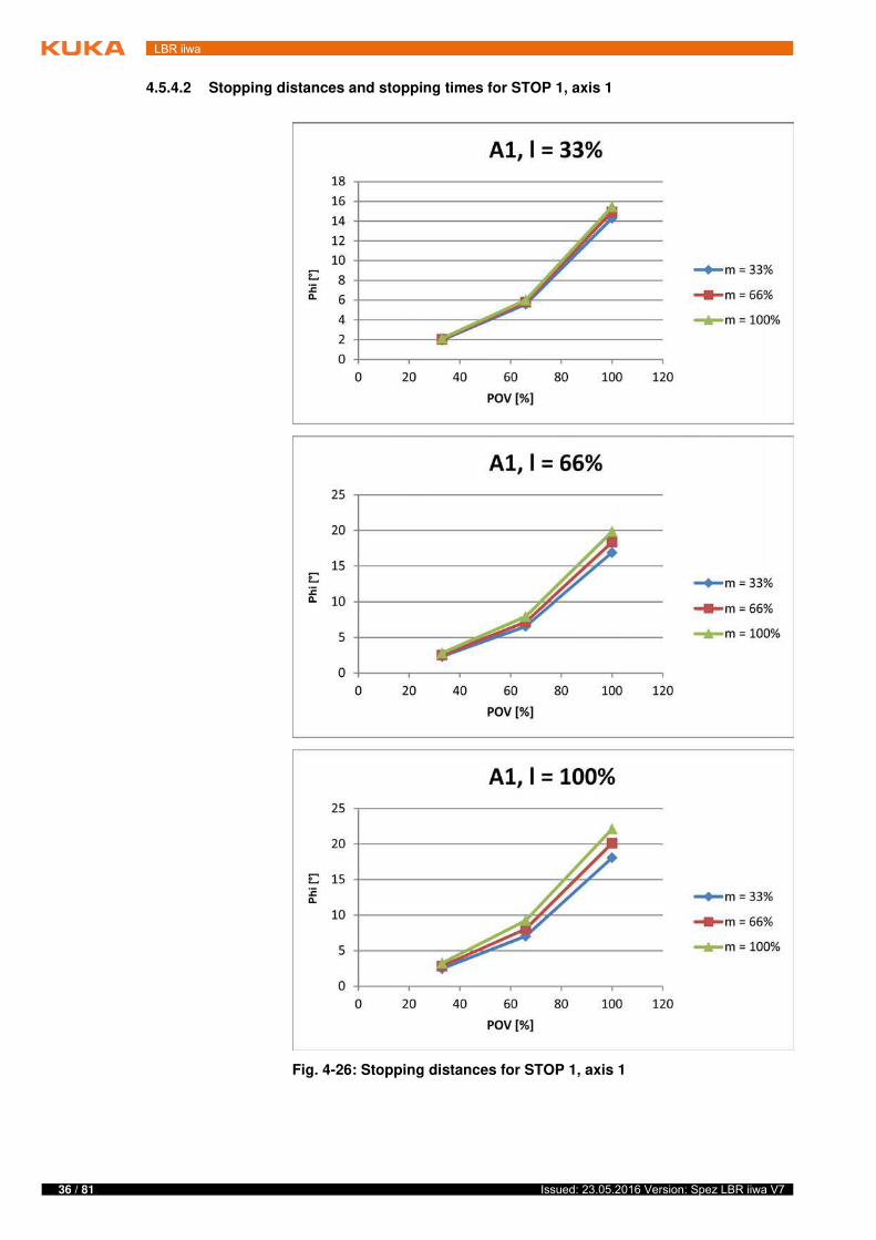
4.5.4.2 Stopping distances and stopping times for STOP 1, axis 1
Fig. 4-26: Stopping distances for STOP 1, axis 1
37 / 81Issued: 23.05.2016 Version: Spez LBR iiwa V7
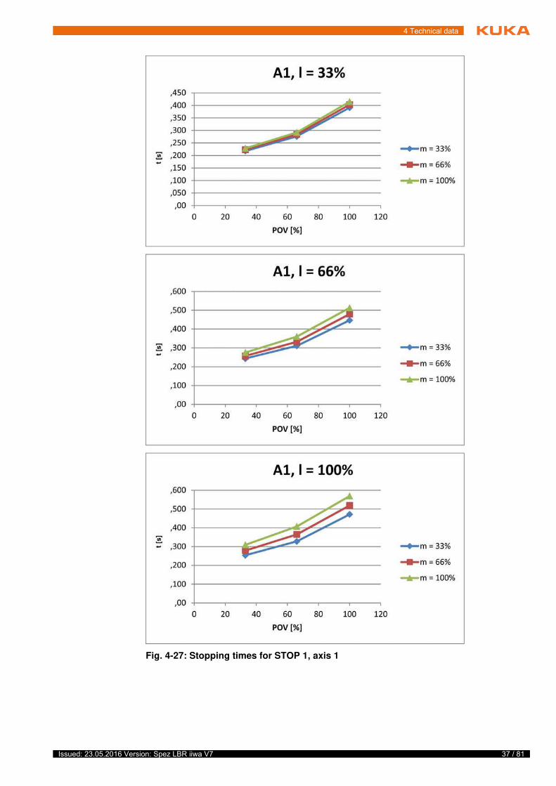
4 Technical data
Fig. 4-27: Stopping times for STOP 1, axis 1
38 / 81 Issued: 23.05.2016 Version: Spez LBR iiwa V7
LBR iiwa
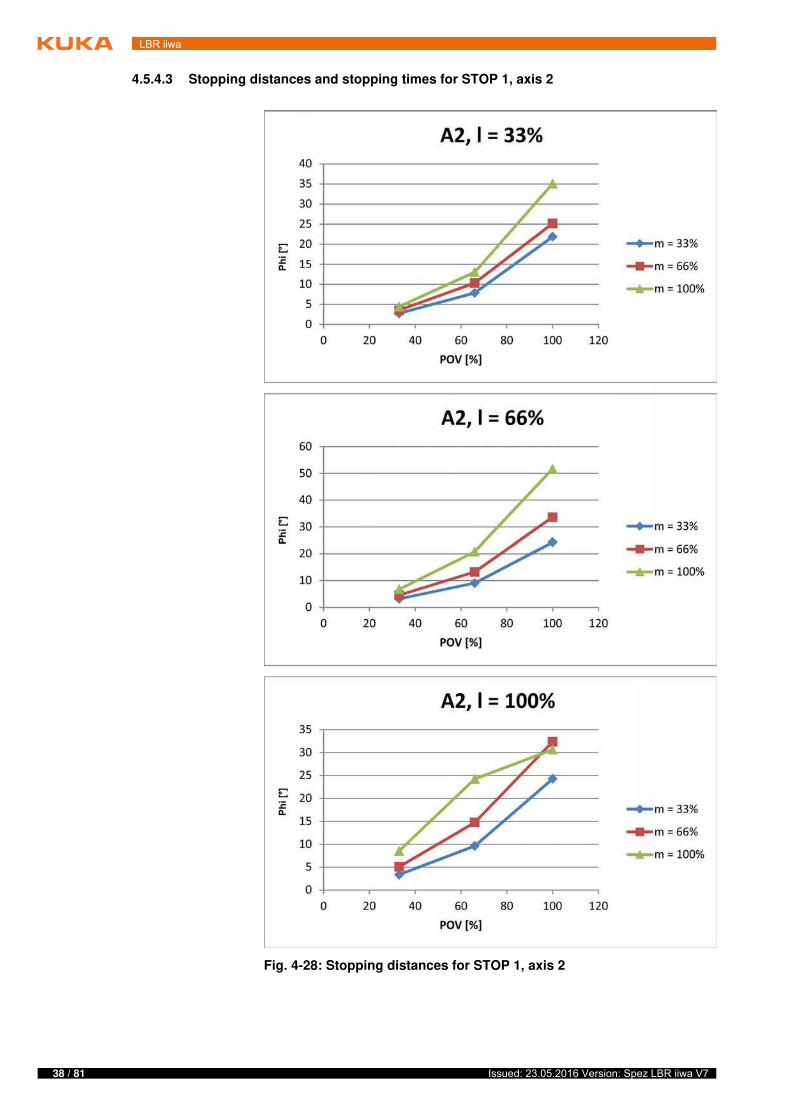
4.5.4.3 Stopping distances and stopping times for STOP 1, axis 2
Fig. 4-28: Stopping distances for STOP 1, axis 2
39 / 81Issued: 23.05.2016 Version: Spez LBR iiwa V7
4 Technical data
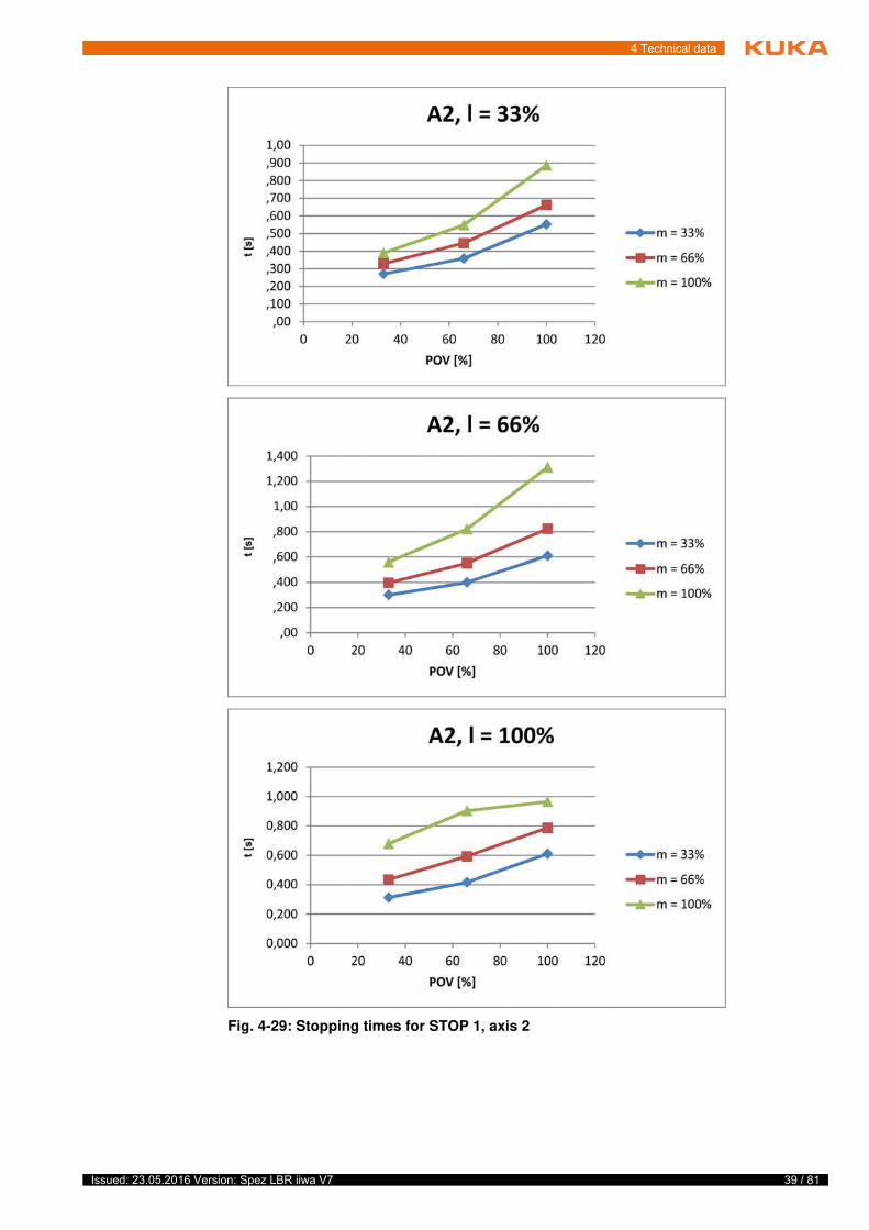
Fig. 4-29: Stopping times for STOP 1, axis 2
40 / 81 Issued: 23.05.2016 Version: Spez LBR iiwa V7
LBR iiwa
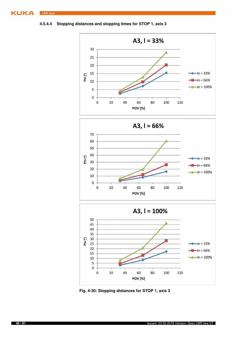
4.5.4.4 Stopping distances and stopping times for STOP 1, axis 3
Fig. 4-30: Stopping distances for STOP 1, axis 3
41 / 81Issued: 23.05.2016 Version: Spez LBR iiwa V7
4 Technical data
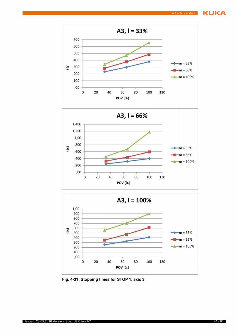
Fig. 4-31: Stopping times for STOP 1, axis 3
42 / 81 Issued: 23.05.2016 Version: Spez LBR iiwa V7
LBR iiwa
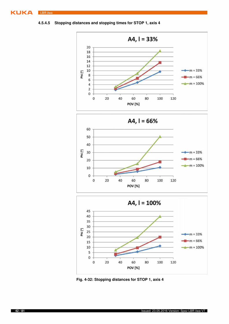
4.5.4.5 Stopping distances and stopping times for STOP 1, axis 4
Fig. 4-32: Stopping distances for STOP 1, axis 4
43 / 81Issued: 23.05.2016 Version: Spez LBR iiwa V7
4 Technical data
Fig. 4-33: Stopping times for STOP 1, axis 4

44 / 81 Issued: 23.05.2016 Version: Spez LBR iiwa V7
LBR iiwa
45 / 81Issued: 23.05.2016 Version: Spez LBR iiwa V7
5 Safety
5 Safety
5.1 Legal framework
5.1.1 Liability
The device described in this document is either an industrial robot or a com-ponent thereof.
Components of the industrial robot:
Manipulator
Robot controller
Hand-held control panel
Connecting cables
Software
Options, accessories
The industrial robot is built using state-of-the-art technology and in accor-dance with the recognized safety rules. Nevertheless, misuse of the industrial robot may constitute a risk to life and limb or cause damage to the industrial robot and to other material property.
The industrial robot may only be used in perfect technical condition in accor-dance with its designated use and only by safety-conscious persons who are fully aware of the risks involved in its operation. Use of the industrial robot is subject to compliance with this document and with the declaration of incorpo-ration supplied together with the industrial robot. Any functional disorders af-fecting safety must be rectified immediately.
Safety infor-
mation
Safety information cannot be held against KUKA Roboter GmbH. Even if all safety instructions are followed, this is not a guarantee that the industrial robot will not cause personal injuries or material damage.
No modifications may be carried out to the industrial robot without the autho-rization of KUKA Roboter GmbH. Additional components (tools, software, etc.), not supplied by KUKA Roboter GmbH, may be integrated into the indus-trial robot. The user is liable for any damage these components may cause to the industrial robot or to other material property.
In addition to the Safety chapter, this document contains further safety instruc-tions. These must also be observed.
5.1.2 Intended use of the industrial robot
The industrial robot is intended exclusively for the use designated in the “Pur-pose” chapter of the operating instructions or assembly instructions.
Any use or application deviating from the intended use is deemed to be misuse and is not allowed. The manufacturer is not liable for any damage resulting from such misuse. The risk lies entirely with the user.
Operation of the industrial robot in accordance with its intended use also re-quires compliance with the operating and assembly instructions for the individ-ual components, with particular reference to the maintenance specifications.
The user is responsible for the performance of a risk analysis. This indicates the additional safety equipment that is required, the installation of which is also the responsibility of the user.
Misuse Any use or application deviating from the intended use is deemed to be misuse and is not allowed. This includes e.g.:
f
t
y
46 / 81 Issued: 23.05.2016 Version: Spez LBR iiwa V7
LBR iiwa
Transportation of persons and animals
Use as a climbing aid
Operation outside the specified operating parameters
Use in potentially explosive environments
Operation without the required additional safety equipment
Outdoor operation
Underground operation
5.1.3 EC declaration of conformity and declaration of incorporation
The industrial robot constitutes partly completed machinery as defined by the EC Machinery Directive. The industrial robot may only be put into operation if the following preconditions are met:
The industrial robot is integrated into a complete system.
or: The industrial robot, together with other machinery, constitutes a com-plete system.
or: All safety functions and safeguards required for operation in the com-plete machine as defined by the EC Machinery Directive have been added to the industrial robot.
The complete system complies with the EC Machinery Directive. This has been confirmed by means of an assessment of conformity.
Declaration of
conformity
The system integrator must issue a declaration of conformity for the complete system in accordance with the Machinery Directive. The declaration of confor-mity forms the basis for the CE mark for the system. The industrial robot must always be operated in accordance with the applicable national laws, regula-tions and standards.
The robot controller is CE certified under the EMC Directive and the Low Volt-age Directive.
Declaration of
incorporation
The partly completed machinery is supplied with a declaration of incorporation in accordance with Annex II B of the EC Machinery Directive 2006/42/EC. The assembly instructions and a list of essential requirements complied with in ac-cordance with Annex I are integral parts of this declaration of incorporation.
The declaration of incorporation declares that the start-up of the partly com-pleted machinery is not allowed until the partly completed machinery has been incorporated into machinery, or has been assembled with other parts to form machinery, and this machinery complies with the terms of the EC Machinery Directive, and the EC declaration of conformity is present in accordance with Annex II A.
5.2 Safety functions
Safety functions are distinguished according to the safety requirements that they fulfill:
Safety-oriented functions for the protection of personnel
The safety-oriented functions of the industrial robot meet the following safety requirements:
Category 3 and Performance Level d in accordance with EN ISO 13849-1
SIL 2 according to EN 62061
The requirements are only met on the following condition, however:
All safety-relevant mechanical and electromechanical components of the industrial robot are tested for correct functioning during start-up
47 / 81Issued: 23.05.2016 Version: Spez LBR iiwa V7
5 Safety
and at least once every 12 months, unless otherwise determined in ac-cordance with a workplace risk assessment. These include:
EMERGENCY STOP device on the smartPAD
Enabling device on the smartPAD
Enabling device on the media flange Touch (if present)
Keyswitch on the smartPAD
Safe outputs of the discrete safety interface
Non-safety-oriented functions for the protection of machines
The non-safety-oriented functions of the industrial robot do not meet spe-cific safety requirements:
5.2.1 Terms used
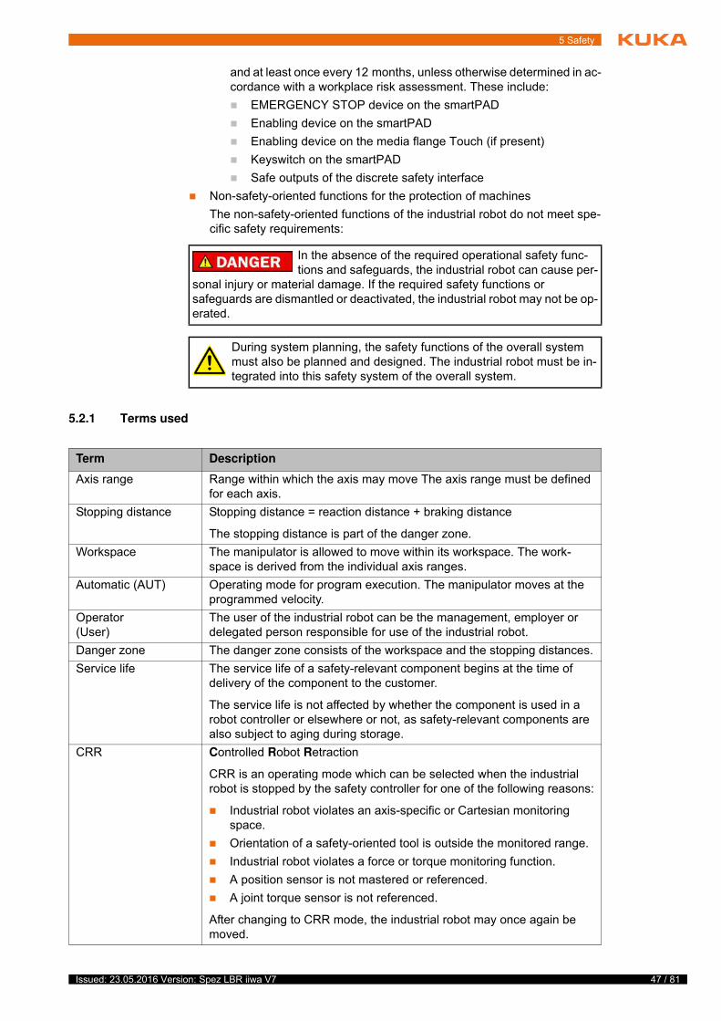
In the absence of the required operational safety func-tions and safeguards, the industrial robot can cause per-
sonal injury or material damage. If the required safety functions or safeguards are dismantled or deactivated, the industrial robot may not be op-erated.
During system planning, the safety functions of the overall system must also be planned and designed. The industrial robot must be in-tegrated into this safety system of the overall system.
Term Description
Axis range Range within which the axis may move The axis range must be defined for each axis.
Stopping distance Stopping distance = reaction distance + braking distance
The stopping distance is part of the danger zone.
Workspace The manipulator is allowed to move within its workspace. The work-space is derived from the individual axis ranges.
Automatic (AUT) Operating mode for program execution. The manipulator moves at the programmed velocity.
Operator(User)
The user of the industrial robot can be the management, employer or delegated person responsible for use of the industrial robot.
Danger zone The danger zone consists of the workspace and the stopping distances.
Service life The service life of a safety-relevant component begins at the time of delivery of the component to the customer.
The service life is not affected by whether the component is used in a robot controller or elsewhere or not, as safety-relevant components are also subject to aging during storage.
CRR Controlled Robot Retraction
CRR is an operating mode which can be selected when the industrial robot is stopped by the safety controller for one of the following reasons:
Industrial robot violates an axis-specific or Cartesian monitoring space.
Orientation of a safety-oriented tool is outside the monitored range.
Industrial robot violates a force or torque monitoring function.
A position sensor is not mastered or referenced.
A joint torque sensor is not referenced.
After changing to CRR mode, the industrial robot may once again be moved.
48 / 81 Issued: 23.05.2016 Version: Spez LBR iiwa V7
LBR iiwa
5.2.2 Personnel
The following persons or groups of persons are defined for the industrial robot:
User
Personnel
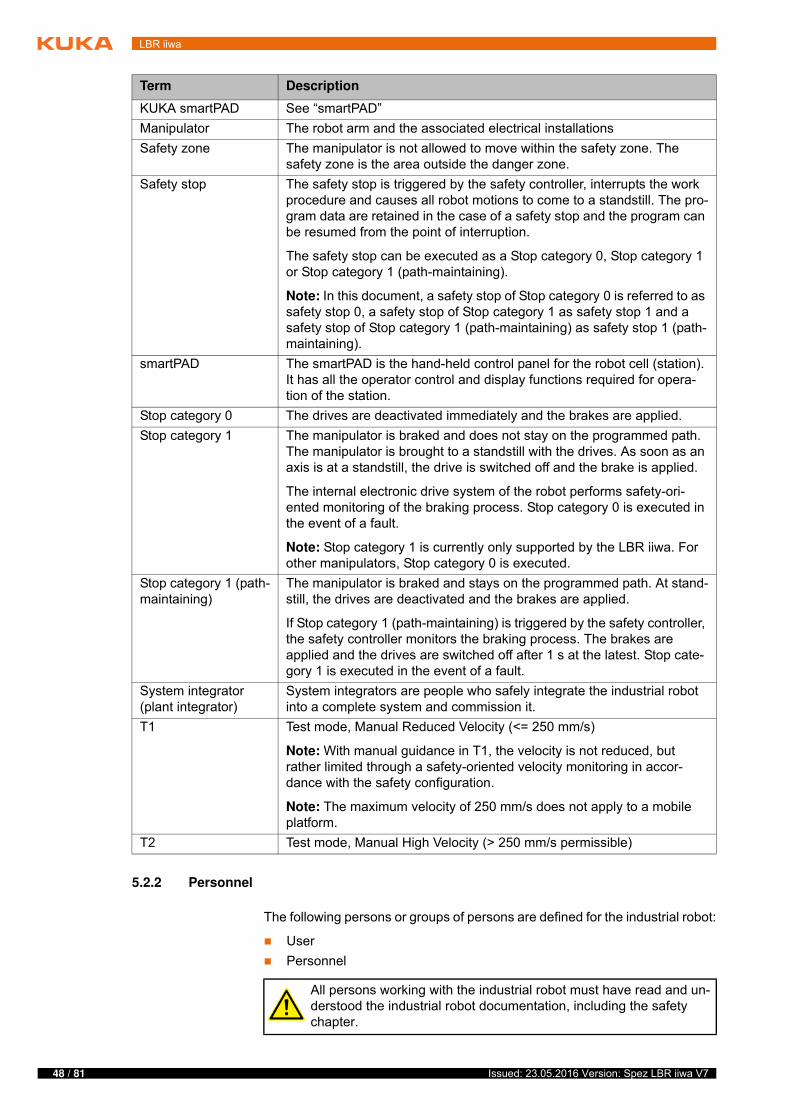
KUKA smartPAD See “smartPAD”
Manipulator The robot arm and the associated electrical installations
Safety zone The manipulator is not allowed to move within the safety zone. The safety zone is the area outside the danger zone.
Safety stop The safety stop is triggered by the safety controller, interrupts the work procedure and causes all robot motions to come to a standstill. The pro-gram data are retained in the case of a safety stop and the program can be resumed from the point of interruption.
The safety stop can be executed as a Stop category 0, Stop category 1 or Stop category 1 (path-maintaining).
Note: In this document, a safety stop of Stop category 0 is referred to as safety stop 0, a safety stop of Stop category 1 as safety stop 1 and a safety stop of Stop category 1 (path-maintaining) as safety stop 1 (path-maintaining).
smartPAD The smartPAD is the hand-held control panel for the robot cell (station). It has all the operator control and display functions required for opera-tion of the station.
Stop category 0 The drives are deactivated immediately and the brakes are applied.
Stop category 1 The manipulator is braked and does not stay on the programmed path. The manipulator is brought to a standstill with the drives. As soon as an axis is at a standstill, the drive is switched off and the brake is applied.
The internal electronic drive system of the robot performs safety-ori-ented monitoring of the braking process. Stop category 0 is executed in the event of a fault.
Note: Stop category 1 is currently only supported by the LBR iiwa. For other manipulators, Stop category 0 is executed.
Stop category 1 (path-maintaining)
The manipulator is braked and stays on the programmed path. At stand-still, the drives are deactivated and the brakes are applied.
If Stop category 1 (path-maintaining) is triggered by the safety controller, the safety controller monitors the braking process. The brakes are applied and the drives are switched off after 1 s at the latest. Stop cate-gory 1 is executed in the event of a fault.
System integrator (plant integrator)
System integrators are people who safely integrate the industrial robot into a complete system and commission it.
T1 Test mode, Manual Reduced Velocity (<= 250 mm/s)
Note: With manual guidance in T1, the velocity is not reduced, but rather limited through a safety-oriented velocity monitoring in accor-dance with the safety configuration.
Note: The maximum velocity of 250 mm/s does not apply to a mobile platform.
T2 Test mode, Manual High Velocity (> 250 mm/s permissible)
Term Description
All persons working with the industrial robot must have read and un-derstood the industrial robot documentation, including the safety chapter.
49 / 81Issued: 23.05.2016 Version: Spez LBR iiwa V7
5 Safety
User The user must observe the labor laws and regulations. This includes e.g.:
The user must comply with his monitoring obligations.
The user must carry out briefing at defined intervals.
Personnel Personnel must be instructed, before any work is commenced, in the type of work involved and what exactly it entails as well as any hazards which may ex-ist. Instruction must be carried out regularly. Instruction is also required after particular incidents or technical modifications.
Personnel includes:
System integrator
Operators, subdivided into:
Start-up, maintenance and service personnel
Operating personnel
Cleaning personnel
System integrator The industrial robot is safely integrated into a complete system by the system integrator.
The system integrator is responsible for the following tasks:
Installing the industrial robot
Connecting the industrial robot
Performing risk assessment
Implementing the required safety functions and safeguards
Issuing the declaration of conformity
Attaching the CE mark
Creating the operating instructions for the complete system
Operator The operator must meet the following preconditions:
The operator must be trained for the work to be carried out.
Work on the industrial robot must only be carried out by qualified person-nel. These are people who, due to their specialist training, knowledge and experience, and their familiarization with the relevant standards, are able to assess the work to be carried out and detect any potential hazards.
5.2.3 Workspace, safety zone and danger zone
Working zones are to be restricted to the necessary minimum size in order to prevent danger to persons or the risk of material damage. Safe axis range lim-itations required for personnel protection are configurable.
The danger zone consists of the workspace and the stopping distances of the manipulator. In the event of a stop, the manipulator is braked and comes to a
Installation, exchange, adjustment, operation, maintenance and re-pair must be performed only as specified in the operating or assembly instructions for the relevant component of the industrial robot and only
by personnel specially trained for this purpose.
Work on the electrical and mechanical equipment of the manipulator may only be carried out by KUKA Roboter GmbH.
Further information about configuring safe axis range limitations is contained in the “Safety configuration” chapter of the operating and programming instructions.
50 / 81 Issued: 23.05.2016 Version: Spez LBR iiwa V7
LBR iiwa
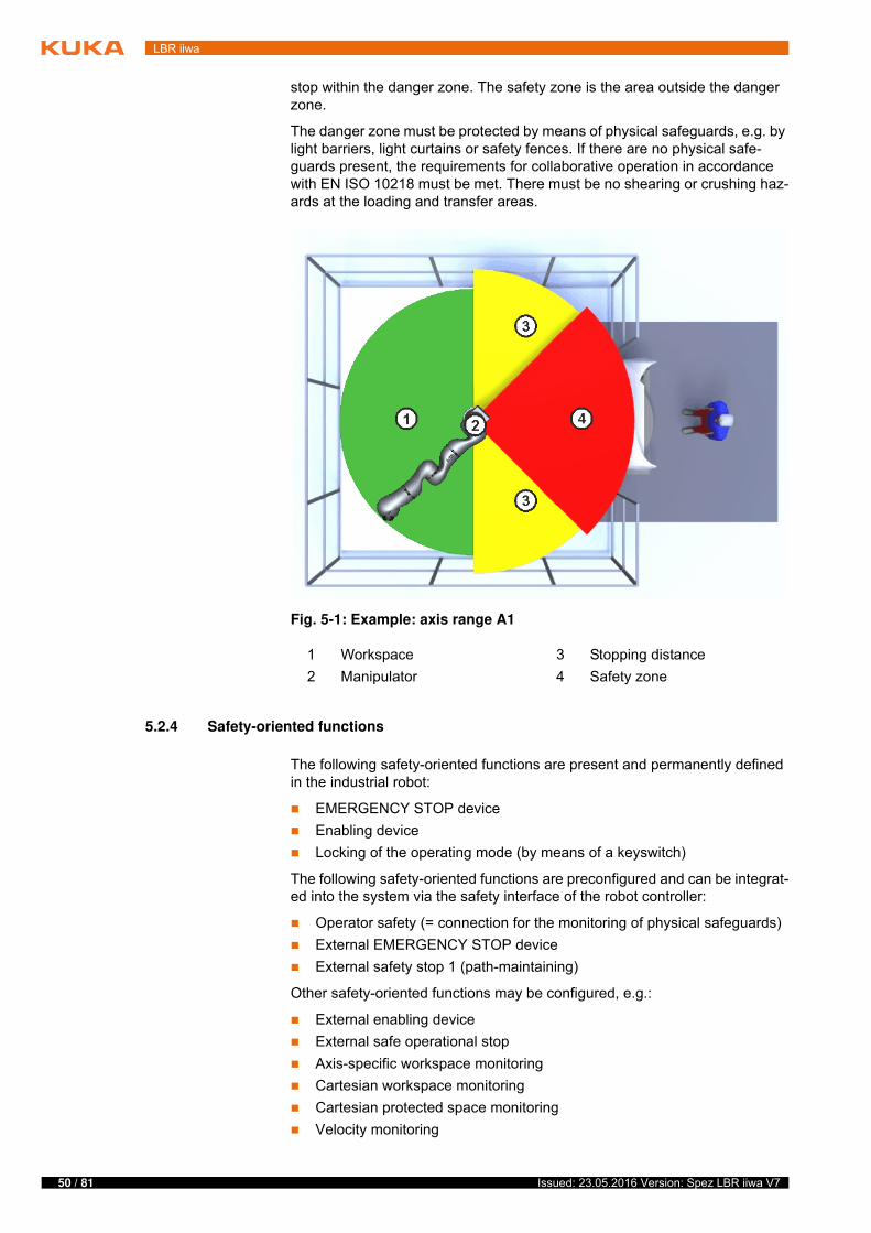
stop within the danger zone. The safety zone is the area outside the danger zone.
The danger zone must be protected by means of physical safeguards, e.g. by light barriers, light curtains or safety fences. If there are no physical safe-guards present, the requirements for collaborative operation in accordance with EN ISO 10218 must be met. There must be no shearing or crushing haz-ards at the loading and transfer areas.
5.2.4 Safety-oriented functions
The following safety-oriented functions are present and permanently defined in the industrial robot:
EMERGENCY STOP device
Enabling device
Locking of the operating mode (by means of a keyswitch)
The following safety-oriented functions are preconfigured and can be integrat-ed into the system via the safety interface of the robot controller:
Operator safety (= connection for the monitoring of physical safeguards)
External EMERGENCY STOP device
External safety stop 1 (path-maintaining)
Other safety-oriented functions may be configured, e.g.:
External enabling device
External safe operational stop
Axis-specific workspace monitoring
Cartesian workspace monitoring
Cartesian protected space monitoring
Velocity monitoring
Fig. 5-1: Example: axis range A1
1 Workspace 3 Stopping distance
2 Manipulator 4 Safety zone
51 / 81Issued: 23.05.2016 Version: Spez LBR iiwa V7
5 Safety
Standstill monitoring
Axis torque monitoring
Collision detection
The preconfigured safety functions are described in the following sections on safety.
5.2.4.1 EMERGENCY STOP device
The EMERGENCY STOP device for the industrial robot is the EMERGENCY STOP device on the smartPAD. The device must be pressed in the event of a hazardous situation or emergency.
Reaction of the industrial robot if the EMERGENCY STOP device is pressed:
The manipulator stops with a safety stop 1 (path-maintaining).
Before operation can be resumed, the EMERGENCY STOP device must be turned to release it.
If a holder is used for the smartPAD and conceals the EMERGENCY STOP device on the smartPAD, an external EMERGENCY STOP device must be in-stalled that is accessible at all times.
(>>> 5.2.4.4 "External EMERGENCY STOP device" Page 52)
5.2.4.2 Enabling device
The enabling devices of the industrial robot are the enabling switches on the smartPAD.
There are 3 enabling switches installed on the smartPAD. The enabling switches have 3 positions:
Not pressed
Center position
Fully pressed (panic position)
In the test modes and in CRR, the manipulator can only be moved if one of the enabling switches is held in the central position.
Releasing the enabling switch triggers a safety stop 1 (path-maintaining).
Fully pressing the enabling switch triggers a safety stop 1 (path-maintain-ing).
It is possible to hold 2 enabling switches in the center position simultane-ously for several seconds. This makes it possible to adjust grip from one enabling switch to another one. If 2 enabling switches are held simultane-ously in the center position for longer than 15 seconds, this triggers a safe-ty stop 1.
If an enabling switch malfunctions (e.g. jams in the central position), the indus-trial robot can be stopped using the following methods:
Press the enabling switch down fully.
Further information about configuring the safety functions is con-tained in the “Safety configuration” chapter of the operating and pro-gramming instructions.
Tools and other equipment connected to the manipulator must be integrated into the EMERGENCY STOP circuit
on the system side if they could constitute a potential hazard.Failure to observe this precaution may result in death, severe injuries or con-siderable damage to property.
52 / 81 Issued: 23.05.2016 Version: Spez LBR iiwa V7
LBR iiwa
Actuate the EMERGENCY STOP device.
Release the Start key.
5.2.4.3 “Operator safety” signal
The “operator safety” signal is used for monitoring physical safeguards, e.g. safety gates. In the default configuration, T2 and automatic operation are not possible without this signal. Alternatively, the requirements for collaborative operation in accordance with EN ISO 10218 must be met.
Reaction of the industrial robot in the event of a loss of signal during T2 or au-tomatic operation (default configuration):
The manipulator stops with a safety stop 1 (path-maintaining).
By default, operator safety is not active in the modes T1 (Manual Reduced Ve-locity) and CRR, i.e. the signal is not evaluated.
5.2.4.4 External EMERGENCY STOP device
Every operator station that can initiate a robot motion or other potentially haz-ardous situation must be equipped with an EMERGENCY STOP device. The system integrator is responsible for ensuring this.
Reaction of the industrial robot if the external EMERGENCY STOP device is pressed (default configuration):
The manipulator stops with a safety stop 1 (path-maintaining).
External EMERGENCY STOP devices are connected via the safety interface of the robot controller. External EMERGENCY STOP devices are not included in the scope of supply of the industrial robot.
5.2.4.5 External safety stop 1 (path-maintaining)
The external safety stop 1 (path-maintaining) can be triggered via an input on the safety interface (default configuration). The state is maintained as long as the external signal is FALSE. If the external signal is TRUE, the manipulator can be moved again. No acknowledgement is required.
The enabling switches must not be held down by adhe-sive tape or other means or tampered with in any other
way.Death, injuries or damage to property may result.
Following a loss of signal, automatic operation must not be resumed merely by closing the safeguard; the signal
for operator safety must first be set by an additional device, e.g. by an ac-knowledge button. It is the responsibility of the system integrator to ensure this. This is to prevent automatic operation from being resumed inadvertently while there are still persons in the danger zone, e.g. due to the safety gate closing accidentally.
This additional device must be designed in such a way that an actual check of the danger zone can be carried out first. Devices that do not al-low this (e.g. because they are automatically triggered by closure of the safeguard) are not permitted.
Failure to observe this may result in death to persons, severe injuries or considerable damage to property.
53 / 81Issued: 23.05.2016 Version: Spez LBR iiwa V7
5 Safety
5.2.4.6 External enabling device
External enabling devices are required if it is necessary for more than one per-son to be in the danger zone of the industrial robot.
Multiple external enabling devices can be connected via the safety interface of the robot controller. External enabling devices are not included in the scope of supply of the industrial robot.
An external enabling device can be used for manual guidance of the robot. When enabling is active, the robot may only be moved at reduced velocity.
For manual guidance, safety-oriented velocity monitoring with a maximum permissible velocity of 250 mm/s is preconfigured. The maximum permissible velocity can be adapted.
The value for the maximum permissible velocity must be determined as part of a risk assessment.
5.2.4.7 External safe operational stop
The safe operational stop is a standstill monitoring function. It does not stop the robot motion, but monitors whether the robot axes are stationary.
The safe operational stop can be triggered via an input on the safety interface. The state is maintained as long as the external signal is FALSE. If the external signal is TRUE, the manipulator can be moved again. No acknowledgement is required.
5.2.5 Triggers for safety-oriented stop reactions
Stop reactions are triggered in response to operator actions or as a reaction to monitoring functions and errors. The following tables show the different stop reactions according to the operating mode that has been set.
Overview In KUKA Sunrise a distinction is made between the following triggers:
Permanently defined triggers
Permanently defined triggers for stop reactions and the associated stop category are preset by the system and cannot be changed. However, it is possible for the implemented stop reaction to be stepped up in the user-specific safety configuration.
User-specific triggers
In addition to the permanently defined triggers, the user can also configure other triggers for stop reactions including the associated stop category.
Permanently
defined triggers
The following triggers for stop reactions are permanently defined:
Further information about configuring the safety functions is con-tained in the “Safety configuration” chapter of the operating and pro-gramming instructions.
Trigger T1, T2, CRR AUT
Operating mode changed during operation
Safety stop 1 (path-maintaining)
Enabling switch released Safety stop 1 (path-maintaining)
-
Enabling switch pressed fully down (panic position)
Safety stop 1 (path-maintaining)
-
Local E-STOP pressed Safety stop 1 (path-maintaining)
Error in safety controller Safety stop 1
54 / 81 Issued: 23.05.2016 Version: Spez LBR iiwa V7
LBR iiwa
User-specific
triggers
The robot controller is shipped with a safety configuration that is active on ini-tial start-up. This contains the following user-specific stop reaction triggers preconfigured by KUKA (in addition to the permanently defined triggers).
When creating a new Sunrise project, the system automatically generates a project-specific safety configuration. This contains the following user-specific stop reaction triggers preconfigured by KUKA (in addition to the permanently defined triggers).
Triggers for
manual guidance
If an enabling device is configured for manual guidance, the following addition-al triggers for stop reactions are permanently defined:
A maximum permissible velocity of 250 mm/s is preconfigured for manual guidance. The maximum permissible velocity can be adapted.
The value for the maximum permissible velocity must be determined as part of a risk assessment.
5.2.6 Non-safety-oriented functions
5.2.6.1 Mode selection
The industrial robot can be operated in the following modes:
Manual Reduced Velocity (T1)
Manual High Velocity (T2)
Automatic (AUT)
Controlled robot retraction (CRR)
Trigger T1, CRR T2, AUT
Safety gate opened (oper-ator safety)
- Safety stop 1 (path-maintaining)
When the Sunrise project is transferred to the robot controller, the fac-tory-set safety configuration is overwritten by the project-specific safety configuration. This makes it necessary for the safety configu-
ration to be activated.Further information about activating the safety configuration is contained in the “Safety configuration” chapter of the operating and programming instruc-tions.
Trigger T1, CRR T2, AUT
Safety gate opened (oper-ator safety)
- Safety stop 1 (path-maintaining)
External E-STOP pressed Safety stop 1 (path-maintaining)
External safety stop Safety stop 1 (path-maintaining)
Trigger T1, CRR T2, AUT
Manual guidance enabling switch released
Safety stop 1 (path-maintaining)
-
Manual guidance enabling switch pressed fully down (panic position)
Safety stop 1 (path-maintaining)
-
Maximum permissible velocity exceeded while manual guidance enabling signal is set
Safety stop 1 (path-maintaining)
55 / 81Issued: 23.05.2016 Version: Spez LBR iiwa V7
5 Safety
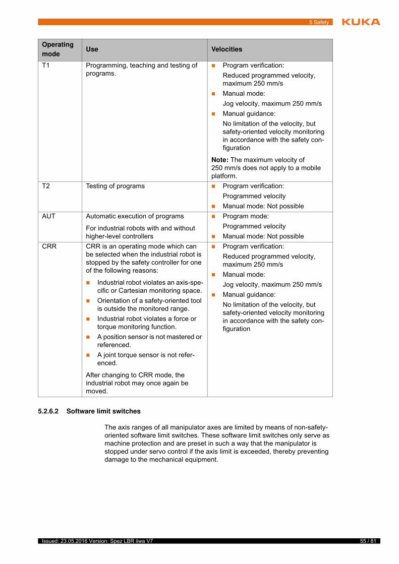
5.2.6.2 Software limit switches
The axis ranges of all manipulator axes are limited by means of non-safety-oriented software limit switches. These software limit switches only serve as machine protection and are preset in such a way that the manipulator is stopped under servo control if the axis limit is exceeded, thereby preventing damage to the mechanical equipment.
Operating
modeUse Velocities
T1 Programming, teaching and testing of programs.
Program verification:
Reduced programmed velocity, maximum 250 mm/s
Manual mode:
Jog velocity, maximum 250 mm/s
Manual guidance:
No limitation of the velocity, but safety-oriented velocity monitoring in accordance with the safety con-figuration
Note: The maximum velocity of 250 mm/s does not apply to a mobile platform.
T2 Testing of programs Program verification:
Programmed velocity
Manual mode: Not possible
AUT Automatic execution of programs
For industrial robots with and without higher-level controllers
Program mode:
Programmed velocity
Manual mode: Not possible
CRR CRR is an operating mode which can be selected when the industrial robot is stopped by the safety controller for one of the following reasons:
Industrial robot violates an axis-spe-cific or Cartesian monitoring space.
Orientation of a safety-oriented tool is outside the monitored range.
Industrial robot violates a force or torque monitoring function.
A position sensor is not mastered or referenced.
A joint torque sensor is not refer-enced.
After changing to CRR mode, the industrial robot may once again be moved.
Program verification:
Reduced programmed velocity, maximum 250 mm/s
Manual mode:
Jog velocity, maximum 250 mm/s
Manual guidance:
No limitation of the velocity, but safety-oriented velocity monitoring in accordance with the safety con-figuration
56 / 81 Issued: 23.05.2016 Version: Spez LBR iiwa V7
LBR iiwa
5.3 Additional protective equipment
5.3.1 Jog mode
In the operating modes T1 (Manual Reduced Velocity), T2 (Manual High Ve-locity) and CRR, the robot controller can only execute programs in jog mode. This means that it is necessary to hold down an enabling switch and the Start key in order to execute a program.
Releasing the enabling switch on the smartPAD triggers a safety stop 1 (path-maintaining).
Pressing fully down on the enabling switch on the smartPAD triggers a safety stop 1 (path-maintaining).
Releasing the Start key triggers a stop of Stop category 1 (path-maintain-ing).
5.3.2 Labeling on the industrial robot
All plates, labels, symbols and marks constitute safety-relevant parts of the in-dustrial robot. They must not be modified or removed.
Labeling on the industrial robot consists of:
Identification plates
Warning signs
Safety symbols
Designation labels
Cable markings
Rating plates
5.3.3 External safeguards
The access of persons to the danger zone of the industrial robot must be pre-vented by means of safeguards. Alternatively, the requirements for collabora-tive operation in accordance with EN ISO 10218 must be met. It is the responsibility of the system integrator to ensure this.
Physical safeguards must meet the following requirements:
They meet the requirements of EN 953.
They prevent access of persons to the danger zone and cannot be easily circumvented.
They are sufficiently fastened and can withstand all forces that are likely to occur in the course of operation, whether from inside or outside the en-closure.
They do not, themselves, represent a hazard or potential hazard.
The prescribed minimum clearance from the danger zone is maintained.
Safety gates (maintenance gates) must meet the following requirements:
They are reduced to an absolute minimum.
The interlocks (e.g. safety gate switches) are linked to the configured op-erator safety inputs of the robot controller.
Further information is contained in the technical data of the operating instructions or assembly instructions of the components of the indus-trial robot.
57 / 81Issued: 23.05.2016 Version: Spez LBR iiwa V7
5 Safety
Switching devices, switches and the type of switching conform to the re-quirements of Performance Level d and category 3 according to EN ISO 13849-1.
Depending on the risk situation: the safety gate is additionally safeguarded by means of a locking mechanism that only allows the gate to be opened if the manipulator is safely at a standstill.
The device for setting the signal for operator safety, e.g. the button for ac-knowledging the safety gate, is located outside the space limited by the safeguards.
Other safety
equipment
Other safety equipment must be integrated into the system in accordance with the corresponding standards and regulations.
5.4 Safety measures
5.4.1 General safety measures
The industrial robot may only be used in perfect technical condition in accor-dance with its intended use and only by safety-conscious persons. Operator errors can result in personal injury and damage to property.
It is important to be prepared for possible movements of the industrial robot even after the robot controller has been switched off and locked out. Incorrect installation (e.g. overload) or mechanical defects (e.g. brake defect) can cause the manipulator to sag. If work is to be carried out on a switched-off industrial robot, the manipulator must first be moved into a position in which it is unable to move on its own, whether the payload is mounted or not. If this is not pos-sible, the manipulator must be secured by appropriate means.
smartPAD The user must ensure that the industrial robot is only operated with the smart-PAD by authorized persons.
If more than one smartPAD is used in the overall system, it must be ensured that each smartPAD is unambiguously assigned to the corresponding indus-trial robot. It must be ensured that 2 smartPADs are not interchanged.
The smartPAD can be configured as unpluggable.
Further information is contained in the corresponding standards and regulations. These also include EN 953.
In the absence of operational safety functions and safe-guards, the industrial robot can cause personal injury or
material damage. If safety functions or safeguards are dismantled or deacti-vated, the industrial robot may not be operated.
Standing underneath the robot arm can cause death or serious injuries. Especially if the industrial robot is mov-
ing objects that can become detached (e.g. from a gripper). For this reason, standing underneath the robot arm is prohibited!
If the smartPAD is disconnected, the system can no lon-ger be switched off by means of the EMERGENCY
STOP device on the smartPAD. If the smartPAD is configured as unplugga-ble, at least one external EMERGENCY STOP device must be installed that is accessible at all times.Failure to observe this can lead to death, injury or property damage.
58 / 81 Issued: 23.05.2016 Version: Spez LBR iiwa V7
LBR iiwa
Modifications After modifications to the industrial robot, checks must be carried out to ensure the required safety level. The valid national or regional work safety regulations must be observed for this check. The correct functioning of all safety functions must also be tested.
New or modified programs must always be tested first in Manual Reduced Ve-locity mode (T1).
After modifications to the industrial robot, existing programs must always be tested first in Manual Reduced Velocity mode (T1). This applies to all compo-nents of the industrial robot and includes modifications to the software and configuration settings.
The robot may not be connected and disconnected when the robot controller is running.
Faults The following tasks must be carried out in the case of faults in the industrial robot:
Switch off the robot controller and secure it (e.g. with a padlock) to prevent unauthorized persons from switching it on again.
Indicate the fault by means of a label with a corresponding warning (tag-out).
Keep a record of the faults.
Eliminate the fault and carry out a function test.
5.4.2 Transportation
Manipulator The prescribed transport position of the manipulator must be observed. Trans-portation must be carried out in accordance with the operating instructions or assembly instructions of the robot.
Avoid vibrations and impacts during transportation in order to prevent damage to the manipulator.
Robot controller The prescribed transport position of the robot controller must be observed. Transportation must be carried out in accordance with the operating instruc-tions or assembly instructions of the robot controller.
Avoid vibrations and impacts during transportation in order to prevent damage to the robot controller.
5.4.3 Start-up and recommissioning
Before starting up systems and devices for the first time, a check must be car-ried out to ensure that the systems and devices are complete and operational, that they can be operated safely and that any damage is detected.
The valid national or regional work safety regulations must be observed for this check. The correct functioning of all safety functions must also be tested.
The operator must ensure that disconnected smartPADs are immediately removed from the system and stored out
of sight and reach of personnel working on the industrial robot. This prevents operational and non-operational EMERGENCY STOP devices from becom-ing interchanged.Failure to observe this can lead to death, injury or property damage.
59 / 81Issued: 23.05.2016 Version: Spez LBR iiwa V7
5 Safety
Function test The following tests must be carried out before start-up and recommissioning:
General test:
It must be ensured that:
The industrial robot is correctly installed and fastened in accordance with the specifications in the documentation.
There are no foreign bodies or loose parts on the industrial robot.
All required safety equipment is correctly installed and operational.
The power supply ratings of the industrial robot correspond to the local supply voltage and mains type.
The ground conductor and the equipotential bonding cable are sufficiently rated and correctly connected.
The connecting cables are correctly connected and the connectors are locked.
Test of the safety functions:
A function test must be carried out for all the safety-oriented functions to en-sure that they are working correctly:
Test of the safety-relevant mechanical and electromechanical compo-
nents:
The following tests must be performed prior to start-up and at least once every 12 months unless otherwise determined in accordance with a workplace risk assessment:
Press the EMERGENCY STOP device on the smartPAD. A message must be displayed on the smartPAD indicating that the EMERGENCY STOP has been actuated. At the same time, no error message may be displayed about the EMERGENCY STOP device.
For all 3 enabling switches on the smartPAD and for the enabling switch on the media flange Touch (if present)
Move the robot in Test mode and release the enabling switch. The robot motion must be stopped. At the same time, no error message may be dis-
Prior to start-up, the passwords for the user groups must be modified in the project settings and transferred to the robot controller in an in-stallation procedure. The passwords must only be communicated to
authorized personnel.
The robot controller is preconfigured for the specific in-dustrial robot. If cables are interchanged, the manipula-
tor may receive incorrect data and can thus cause personal injury or material damage. If a system consists of more than one manipulator, always connect the connecting cables to the manipulators and their corresponding robot con-trollers.
If additional components (e.g. cables), which are not part of the scope of supply of KUKA Roboter GmbH, are integrated into the industrial robot, the user is responsible for ensuring that these components do
not adversely affect or disable safety functions.
If the internal cabinet temperature of the robot controller differs greatly from the ambient temperature, condensa-
tion can form, which may cause damage to the electrical components. Do not put the robot controller into operation until the internal temperature of the cabinet has adjusted to the ambient temperature.
60 / 81 Issued: 23.05.2016 Version: Spez LBR iiwa V7
LBR iiwa
played about the enabling device. If the state of the enabling switch is con-figured at an output, the test can also be performed via the output.
For all 3 enabling switches on the smartPAD and for the enabling switch on the media flange Touch (if present)
Move the robot in Test mode and press the enabling switch down fully. The robot motion must be stopped. At the same time, no error message may be displayed about the enabling device. If the state of the enabling switch is configured at an output, the test can also be performed via the output.
Turn the keyswitch on the smartPAD to the right and then back again. There must be no error message displayed on the smartPAD.
Test the switch-off capability of the safe inputs by switching the robot con-troller off and then on again. After it is switched on, no error message for a safe output may be displayed.
Test of the functional capability of the brakes:
For the KUKA LBR iiwa (all variants) a brake test is available which can be used to check whether the brakes on all axes apply sufficient braking torque.
Unless otherwise determined by a risk assessment, the brake test must be performed regularly:
The brake test must be carried out for each axis during start-up and recom-missioning of the industrial robot.
The brake test must be performed daily during operation.
The user can carry out a risk assessment to determine whether the brake test is required for the specific application and, if so, how often it is to be performed.
5.4.4 Manual mode
Manual mode is the mode for setup work. Setup work is all the tasks that have to be carried out on the industrial robot to enable automatic operation. Setup work includes:
Jog mode
Teaching
Program verification
The following must be taken into consideration in manual mode:
New or modified programs must always be tested first in Manual Reduced Velocity mode (T1).
The manipulator and its tooling must never touch or project beyond the safety fence.
Workpieces, tooling and other objects must not become jammed as a re-sult of the industrial robot motion, nor must they lead to short-circuits or be liable to fall off.
All setup work must be carried out, where possible, from outside the safe-guarded area.
If the setup work has to be carried out inside the safeguarded area, the follow-ing must be taken into consideration:
In the case of incomplete start-up of the system, additional substitute measures for minimizing risk must be taken and documented, e.g. in-stallation of a safety fence, attachment of a warning sign, locking of
the main switch. Start-up is incomplete, for example, if not all safety functions have yet been implemented, or if a function test of the safety functions has not yet been carried out.
61 / 81Issued: 23.05.2016 Version: Spez LBR iiwa V7
5 Safety
In Manual Reduced Velocity mode (T1):
If it can be avoided, there must be no other persons inside the safeguard-ed area.
If it is necessary for there to be several persons inside the safeguarded ar-ea, the following must be observed:
Each person must have an enabling device.
All persons must have an unimpeded view of the industrial robot.
Eye-contact between all persons must be possible at all times.
The operator must be so positioned that he can see into the danger area and get out of harm’s way.
In Manual High Velocity mode (T2):
This mode may only be used if the application requires a test at a velocity higher than Manual Reduced Velocity.
Teaching is not permissible in this operating mode.
Before commencing the test, the operator must ensure that the enabling devices are operational.
There must be no-one present inside the safeguarded area. It is the re-sponsibility of the operator to ensure this.
5.4.5 Automatic mode
Automatic mode is only permissible in compliance with the following safety measures:
All safety equipment and safeguards are present and operational.
There are no persons in the system, or the requirements for collaborative operation in accordance with EN ISO 10218 have been met.
The defined working procedures are adhered to.
If the manipulator comes to a standstill for no apparent reason, the danger zone must not be entered until an EMERGENCY STOP has been triggered.
5.4.6 Maintenance and repair
After maintenance and repair work, checks must be carried out to ensure the required safety level. The valid national or regional work safety regulations must be observed for this check. The correct functioning of all safety functions must also be tested.
The purpose of maintenance and repair work is to ensure that the system is kept operational or, in the event of a fault, to return the system to an operation-al state. Repair work includes troubleshooting in addition to the actual repair itself.
The following safety measures must be carried out when working on the indus-trial robot:
Carry out work outside the danger zone. If work inside the danger zone is necessary, the user must define additional safety measures to ensure the safe protection of personnel.
Switch off the industrial robot and secure it (e.g. with a padlock) to prevent it from being switched on again. If it is necessary to carry out work with the robot controller switched on, the user must define additional safety mea-sures to ensure the safe protection of personnel.
If it is necessary to carry out work with the robot controller switched on, this may only be done in operating mode T1.
62 / 81 Issued: 23.05.2016 Version: Spez LBR iiwa V7
LBR iiwa
Label the system with a sign indicating that work is in progress. This sign must remain in place, even during temporary interruptions to the work.
The EMERGENCY STOP devices must remain active. If safety functions or safeguards are deactivated during maintenance or repair work, they must be reactivated immediately after the work is completed.
Faulty components must be replaced using new components with the same article numbers or equivalent components approved by KUKA Roboter GmbH for this purpose.
Cleaning and preventive maintenance work is to be carried out in accordance with the operating instructions.
Robot controller Even when the robot controller is switched off, parts connected to peripheral devices may still carry voltage. The external power sources must therefore be switched off if work is to be carried out on the robot controller.
The ESD regulations must be adhered to when working on components in the robot controller.
Voltages in excess of 60 V can be present in various components for several minutes after the robot controller has been switched off! To prevent life-threat-ening injuries, no work may be carried out on the industrial robot in this time.
Water and dust must be prevented from entering the robot controller.
5.4.7 Decommissioning, storage and disposal
The industrial robot must be decommissioned, stored and disposed of in ac-cordance with the applicable national laws, regulations and standards.
5.4.8 Safety measures for “single point of control”
Overview If certain components in the industrial robot are operated, safety measures must be taken to ensure complete implementation of the principle of “single point of control” (SPOC).
Components:
Tools for configuration of bus systems with online functionality
Since only the system integrator knows the safe states of actuators in the pe-riphery of the robot controller, it is his task to set these actuators to a safe state.
T1, T2, CRR In modes T1, T2 and CRR, a robot motion can only be initiated if an enabling switch is held down.
Before work is commenced on live parts of the robot sys-tem, the main switch must be turned off and secured
against being switched on again. The system must then be checked to en-sure that it is deenergized.It is not sufficient, before commencing work on live parts, to execute an EMERGENCY STOP or a safety stop, or to switch off the drives, as this does not disconnect the robot system from the mains power supply. Parts remain energized. Death or severe injuries may result.
The implementation of additional safety measures may be required. This must be clarified for each specific application; this is the respon-sibility of the user of the system.
63 / 81Issued: 23.05.2016 Version: Spez LBR iiwa V7
5 Safety
Tools for configu-
ration of bus
systems
If these components have an online functionality, they can be used with write access to modify programs, outputs or other parameters of the robot control-ler, without this being noticed by any persons located inside the system.
KUKA Sunrise.Workbench
WorkVisual from KUKA
Tools from other manufacturers
Safety measure:
In the test modes, programs, outputs or other parameters of the robot con-troller must not be modified using these components.
5.5 Applied norms and directives
Name Definition Edition
2006/42/EC Machinery Directive:
Directive 2006/42/EC of the European Parliament and of the Council of 17 May 2006 on machinery, and amending Direc-tive 95/16/EC (recast)
2006
2014/30/EU EMC Directive:
Directive 2014/30/EC of the European Parliament and of the Council of 26 February 2014 on the approximation of the laws of the Member States concerning electromagnetic compatibil-ity
2014
EN ISO 13850 Safety of machinery:
Emergency stop - Principles for design
2008
EN ISO 13849-1 Safety of machinery:
Safety-related parts of control systems - Part 1: General prin-ciples of design
2008
EN ISO 13849-2 Safety of machinery:
Safety-related parts of control systems - Part 2: Validation
2012
EN ISO 12100 Safety of machinery:
General principles of design, risk assessment and risk reduc-tion
2010
EN ISO 10218-1 Industrial robots – Safety requirements
Part 1: Robot
Note: Content equivalent to ANSI/RIA R.15.06-2012, Part 1
2011
EN 614-1 + A1 Safety of machinery:
Ergonomic design principles - Part 1: Terms and general prin-ciples
2009
EN 61000-6-2 Electromagnetic compatibility (EMC):
Part 6-2: Generic standards; Immunity for industrial environ-ments
2005

64 / 81 Issued: 23.05.2016 Version: Spez LBR iiwa V7
LBR iiwa
EN 61000-6-4 + A1 Electromagnetic compatibility (EMC):
Part 6-4: Generic standards; Emission standard for industrial environments
2011
EN 60204-1 + A1 Safety of machinery:
Electrical equipment of machines - Part 1: General require-ments
2009
EN 62061 + A1 Safety of machinery:
Functional safety of safety-related electrical, electronic and programmable electronic control systems
2012
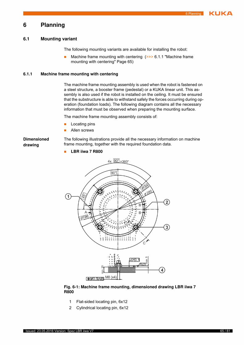
65 / 81Issued: 23.05.2016 Version: Spez LBR iiwa V7
6 Planning
6 Planning
6.1 Mounting variant
The following mounting variants are available for installing the robot:
Machine frame mounting with centering (>>> 6.1.1 "Machine frame mounting with centering" Page 65)
6.1.1 Machine frame mounting with centering
The machine frame mounting assembly is used when the robot is fastened on a steel structure, a booster frame (pedestal) or a KUKA linear unit. This as-sembly is also used if the robot is installed on the ceiling. It must be ensured that the substructure is able to withstand safely the forces occurring during op-eration (foundation loads). The following diagram contains all the necessary information that must be observed when preparing the mounting surface.
The machine frame mounting assembly consists of:
Locating pins
Allen screws
Dimensioned
drawing
The following illustrations provide all the necessary information on machine frame mounting, together with the required foundation data.
LBR iiwa 7 R800
Fig. 6-1: Machine frame mounting, dimensioned drawing LBR iiwa 7
R800
1 Flat-sided locating pin, 6x12
2 Cylindrical locating pin, 6x12
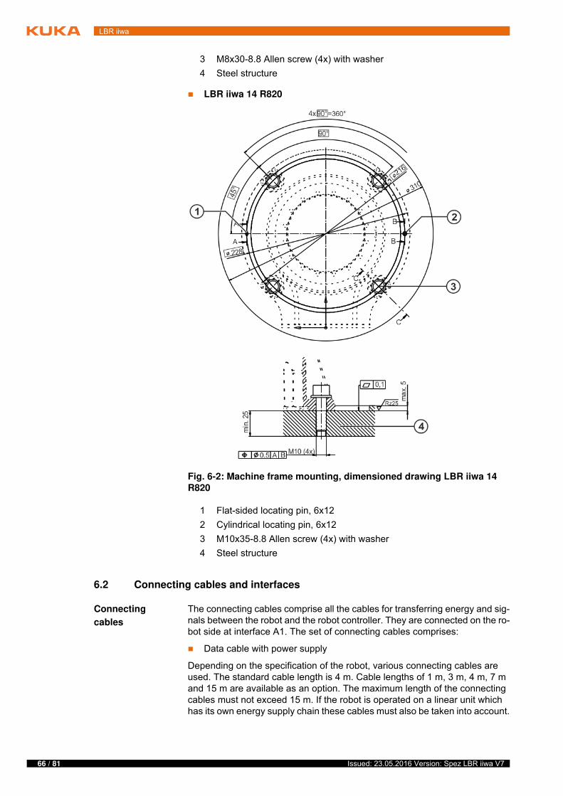
66 / 81 Issued: 23.05.2016 Version: Spez LBR iiwa V7
LBR iiwa
LBR iiwa 14 R820
6.2 Connecting cables and interfaces
Connecting
cables
The connecting cables comprise all the cables for transferring energy and sig-nals between the robot and the robot controller. They are connected on the ro-bot side at interface A1. The set of connecting cables comprises:
Data cable with power supply
Depending on the specification of the robot, various connecting cables are used. The standard cable length is 4 m. Cable lengths of 1 m, 3 m, 4 m, 7 m and 15 m are available as an option. The maximum length of the connecting cables must not exceed 15 m. If the robot is operated on a linear unit which has its own energy supply chain these cables must also be taken into account.
3 M8x30-8.8 Allen screw (4x) with washer
4 Steel structure
Fig. 6-2: Machine frame mounting, dimensioned drawing LBR iiwa 14
R820
1 Flat-sided locating pin, 6x12
2 Cylindrical locating pin, 6x12
3 M10x35-8.8 Allen screw (4x) with washer
4 Steel structure

67 / 81Issued: 23.05.2016 Version: Spez LBR iiwa V7
6 Planning
The following points must be observed when planning and routing the con-necting cables:
The bending radius for fixed routing must not be less than 45 mm for data cables.
Protect cables against exposure to mechanical stress.
Route the cables without mechanical stress – no tensile forces on the con-nectors
Cables are only to be installed indoors.
Observe permissible temperature range (fixed installation) of 263 K (-10 °C) to 343 K (+70 °C).
Route the connecting cable in a metal duct; if necessary, additional mea-sures must be taken to ensure electromagnetic compatibility (EMC).

68 / 81 Issued: 23.05.2016 Version: Spez LBR iiwa V7
LBR iiwa
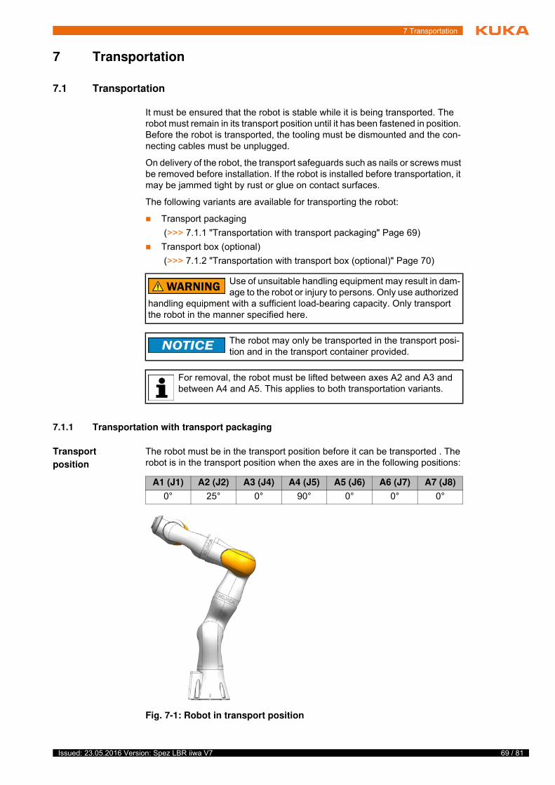
69 / 81Issued: 23.05.2016 Version: Spez LBR iiwa V7
7 Transportation
7 Transportation
7.1 Transportation
It must be ensured that the robot is stable while it is being transported. The robot must remain in its transport position until it has been fastened in position. Before the robot is transported, the tooling must be dismounted and the con-necting cables must be unplugged.
On delivery of the robot, the transport safeguards such as nails or screws must be removed before installation. If the robot is installed before transportation, it may be jammed tight by rust or glue on contact surfaces.
The following variants are available for transporting the robot:
Transport packaging
(>>> 7.1.1 "Transportation with transport packaging" Page 69)
Transport box (optional)
(>>> 7.1.2 "Transportation with transport box (optional)" Page 70)
7.1.1 Transportation with transport packaging
Transport
position
The robot must be in the transport position before it can be transported . The robot is in the transport position when the axes are in the following positions:
T
s
t
t
Use of unsuitable handling equipment may result in dam-age to the robot or injury to persons. Only use authorized
handling equipment with a sufficient load-bearing capacity. Only transport the robot in the manner specified here.
The robot may only be transported in the transport posi-tion and in the transport container provided.
For removal, the robot must be lifted between axes A2 and A3 and between A4 and A5. This applies to both transportation variants.
A1 (J1) A2 (J2) A3 (J4) A4 (J5) A5 (J6) A6 (J7) A7 (J8)
0° 25° 0° 90° 0° 0° 0°
Fig. 7-1: Robot in transport position
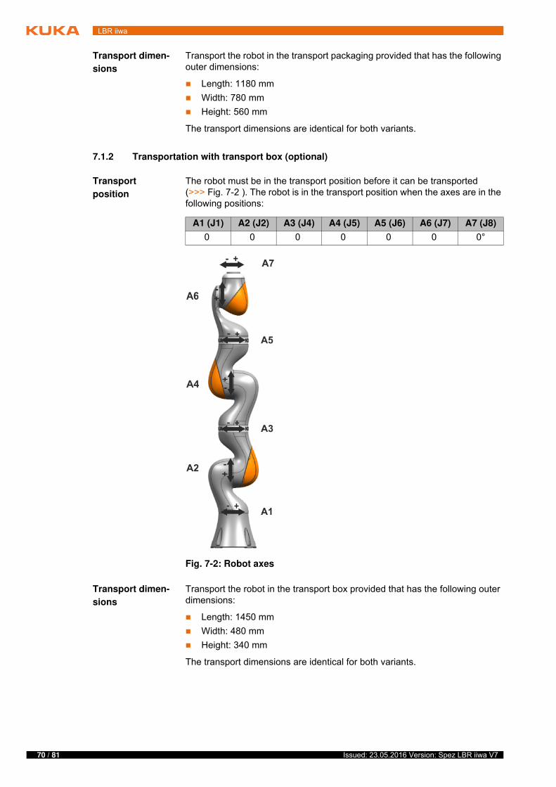
70 / 81 Issued: 23.05.2016 Version: Spez LBR iiwa V7
LBR iiwa
Transport dimen-
sions
Transport the robot in the transport packaging provided that has the following outer dimensions:
Length: 1180 mm
Width: 780 mm
Height: 560 mm
The transport dimensions are identical for both variants.
7.1.2 Transportation with transport box (optional)
Transport
position
The robot must be in the transport position before it can be transported (>>> Fig. 7-2 ). The robot is in the transport position when the axes are in the following positions:
Transport dimen-
sions
Transport the robot in the transport box provided that has the following outer dimensions:
Length: 1450 mm
Width: 480 mm
Height: 340 mm
The transport dimensions are identical for both variants.
A1 (J1) A2 (J2) A3 (J4) A4 (J5) A5 (J6) A6 (J7) A7 (J8)
0 0 0 0 0 0 0°
Fig. 7-2: Robot axes
71 / 81Issued: 23.05.2016 Version: Spez LBR iiwa V7
8 KUKA Service
8 KUKA Service
8.1 Requesting support
Introduction This documentation provides information on operation and operator control, and provides assistance with troubleshooting. For further assistance, please contact your local KUKA subsidiary.
Information The following information is required for processing a support request:
Description of the problem, including information about the duration and frequency of the fault
As comprehensive information as possible about the hardware and soft-ware components of the overall system
The following list gives an indication of the information which is relevant in many cases:
Model and serial number of the kinematic system, e.g. the manipulator
Model and serial number of the controller
Model and serial number of the energy supply system
Designation and version of the system software
Designations and versions of other software components or modifica-tions
Diagnostic package KRCDiag
Additionally for KUKA Sunrise: Existing projects including applications
For versions of KUKA System Software older than V8: Archive of the software (KRCDiag is not yet available here.)
Application used
External axes used
8.2 KUKA Customer Support
Availability KUKA Customer Support is available in many countries. Please do not hesi-tate to contact us if you have any questions.
Argentina Ruben Costantini S.A. (Agency)
Luis Angel Huergo 13 20
Parque Industrial
2400 San Francisco (CBA)
Argentina
Tel. +54 3564 421033
Fax +54 3564 428877
Australia KUKA Robotics Australia Pty Ltd
45 Fennell Street
Port Melbourne VIC 3207
Australia
Tel. +61 3 9939 9656
www.kuka-robotics.com.au
A
v
72 / 81 Issued: 23.05.2016 Version: Spez LBR iiwa V7
LBR iiwa
Belgium KUKA Automatisering + Robots N.V.
Centrum Zuid 1031
3530 Houthalen
Belgium
Tel. +32 11 516160
Fax +32 11 526794
www.kuka.be
Brazil KUKA Roboter do Brasil Ltda.
Travessa Claudio Armando, nº 171
Bloco 5 - Galpões 51/52
Bairro Assunção
CEP 09861-7630 São Bernardo do Campo - SP
Brazil
Tel. +55 11 4942-8299
Fax +55 11 2201-7883
www.kuka-roboter.com.br
Chile Robotec S.A. (Agency)
Santiago de Chile
Chile
Tel. +56 2 331-5951
Fax +56 2 331-5952
www.robotec.cl
China KUKA Robotics China Co., Ltd.
No. 889 Kungang Road
Xiaokunshan Town
Songjiang District
201614 Shanghai
P. R. China
Tel. +86 21 5707 2688
Fax +86 21 5707 2603
www.kuka-robotics.com
Germany KUKA Roboter GmbH
Zugspitzstr. 140
86165 Augsburg
Germany
Tel. +49 821 797-4000
Fax +49 821 797-4040
www.kuka-robotics.com
73 / 81Issued: 23.05.2016 Version: Spez LBR iiwa V7
8 KUKA Service
France KUKA Automatisme + Robotique SAS
Techvallée
6, Avenue du Parc
91140 Villebon S/Yvette
France
Tel. +33 1 6931660-0
Fax +33 1 6931660-1
www.kuka.fr
India KUKA Robotics India Pvt. Ltd.
Office Number-7, German Centre,
Level 12, Building No. - 9B
DLF Cyber City Phase III
122 002 Gurgaon
Haryana
India
Tel. +91 124 4635774
Fax +91 124 4635773
www.kuka.in
Italy KUKA Roboter Italia S.p.A.
Via Pavia 9/a - int.6
10098 Rivoli (TO)
Italy
Tel. +39 011 959-5013
Fax +39 011 959-5141
www.kuka.it
Japan KUKA Robotics Japan K.K.
YBP Technical Center
134 Godo-cho, Hodogaya-ku
Yokohama, Kanagawa
240 0005
Japan
Tel. +81 45 744 7691
Fax +81 45 744 7696
Canada KUKA Robotics Canada Ltd.
6710 Maritz Drive - Unit 4
Mississauga
L5W 0A1
Ontario
Canada
Tel. +1 905 670-8600
Fax +1 905 670-8604
www.kuka-robotics.com/canada
74 / 81 Issued: 23.05.2016 Version: Spez LBR iiwa V7
LBR iiwa
Korea KUKA Robotics Korea Co. Ltd.
RIT Center 306, Gyeonggi Technopark
1271-11 Sa 3-dong, Sangnok-gu
Ansan City, Gyeonggi Do
426-901
Korea
Tel. +82 31 501-1451
Fax +82 31 501-1461
Malaysia KUKA Robot Automation (M) Sdn Bhd
South East Asia Regional Office
No. 7, Jalan TPP 6/6
Taman Perindustrian Puchong
47100 Puchong
Selangor
Malaysia
Tel. +60 (03) 8063-1792
Fax +60 (03) 8060-7386
Mexico KUKA de México S. de R.L. de C.V.
Progreso #8
Col. Centro Industrial Puente de Vigas
Tlalnepantla de Baz
54020 Estado de México
Mexico
Tel. +52 55 5203-8407
Fax +52 55 5203-8148
www.kuka-robotics.com/mexico
Norway KUKA Sveiseanlegg + Roboter
Sentrumsvegen 5
2867 Hov
Norway
Tel. +47 61 18 91 30
Fax +47 61 18 62 00
Austria KUKA Roboter CEE GmbH
Gruberstraße 2-4
4020 Linz
Austria
Tel. +43 7 32 78 47 52
Fax +43 7 32 79 38 80
www.kuka.at
75 / 81Issued: 23.05.2016 Version: Spez LBR iiwa V7
8 KUKA Service
Poland KUKA Roboter Austria GmbH
Spółka z ograniczoną odpowiedzialnościąOddział w Polsce
Ul. Porcelanowa 10
40-246 Katowice
Poland
Tel. +48 327 30 32 13 or -14
Fax +48 327 30 32 26
Portugal KUKA Robots IBÉRICA, S.A.
Rua do Alto da Guerra n° 50
Armazém 04
2910 011 Setúbal
Portugal
Tel. +351 265 729 780
Fax +351 265 729 782
www.kuka.com
Russia KUKA Robotics RUS
Werbnaja ul. 8A
107143 Moskau
Russia
Tel. +7 495 781-31-20
Fax +7 495 781-31-19
www.kuka-robotics.ru
Sweden KUKA Svetsanläggningar + Robotar AB
A. Odhners gata 15
421 30 Västra Frölunda
Sweden
Tel. +46 31 7266-200
Fax +46 31 7266-201
Switzerland KUKA Roboter Schweiz AG
Industriestr. 9
5432 Neuenhof
Switzerland
Tel. +41 44 74490-90
Fax +41 44 74490-91
www.kuka-roboter.ch
76 / 81 Issued: 23.05.2016 Version: Spez LBR iiwa V7
LBR iiwa
Spain KUKA Robots IBÉRICA, S.A.
Pol. Industrial
Torrent de la Pastera
Carrer del Bages s/n
08800 Vilanova i la Geltrú (Barcelona)
Spain
Tel. +34 93 8142-353
Fax +34 93 8142-950
www.kuka.es
South Africa Jendamark Automation LTD (Agency)
76a York Road
North End
6000 Port Elizabeth
South Africa
Tel. +27 41 391 4700
Fax +27 41 373 3869
www.jendamark.co.za
Taiwan KUKA Robot Automation Taiwan Co., Ltd.
No. 249 Pujong Road
Jungli City, Taoyuan County 320
Taiwan, R. O. C.
Tel. +886 3 4331988
Fax +886 3 4331948
www.kuka.com.tw
Thailand KUKA Robot Automation (M)SdnBhd
Thailand Office
c/o Maccall System Co. Ltd.
49/9-10 Soi Kingkaew 30 Kingkaew Road
Tt. Rachatheva, A. Bangpli
Samutprakarn
10540 Thailand
Tel. +66 2 7502737
Fax +66 2 6612355
www.kuka-roboter.de
Czech Republic KUKA Roboter Austria GmbH
Organisation Tschechien und Slowakei
Sezemická 2757/2
193 00 Praha
Horní Počernice
Czech Republic
Tel. +420 22 62 12 27 2
Fax +420 22 62 12 27 0
77 / 81Issued: 23.05.2016 Version: Spez LBR iiwa V7
8 KUKA Service
Hungary KUKA Robotics Hungaria Kft.
Fö út 140
2335 Taksony
Hungary
Tel. +36 24 501609
Fax +36 24 477031
USA KUKA Robotics Corporation
51870 Shelby Parkway
Shelby Township
48315-1787
Michigan
USA
Tel. +1 866 873-5852
Fax +1 866 329-5852
www.kukarobotics.com
UK KUKA Robotics UK Ltd
Great Western Street
Wednesbury West Midlands
WS10 7LL
UK
Tel. +44 121 505 9970
Fax +44 121 505 6589
www.kuka-robotics.co.uk

78 / 81 Issued: 23.05.2016 Version: Spez LBR iiwa V7
LBR iiwa
79 / 81Issued: 23.05.2016 Version: Spez LBR iiwa V7
Index
Index
Numbers
2006/42/EC 632014/30/EU 6395/16/EC 63
A
Accessories 9, 45Angle of rotation 24ANSI/RIA R.15.06-2012 63Applied norms and directives 63AUT 47Automatic 47Automatic mode 61Axis data, LBR iiwa 14 R820 17Axis data, LBR iiwa 7 R800 12Axis range 47
B
Basic data, LBR iiwa 14 R820 17Basic data, LBR iiwa 7 R800 11Brake defect 57Braking distance 47
C
CE mark 46Cleaning work 62Connecting cables 9, 45Connecting cables and interfaces 66CRR 47
D
Danger zone 47Declaration of conformity 46Declaration of incorporation 45, 46Decommissioning 62Disposal 62Documentation, industrial robot 5
E
EC declaration of conformity 46Electromagnetic compatibility (EMC) 63, 64EMC Directive 46, 63EMERGENCY STOP device 50, 51, 52EMERGENCY STOP, external 50, 52EN 60204-1 + A1 64EN 61000-6-2 63EN 61000-6-4 + A1 64EN 614-1 + A1 63EN 62061 + A1 64EN ISO 10218-1 63EN ISO 12100 63EN ISO 13849-1 63EN ISO 13849-2 63EN ISO 13850 63Enabling device 50, 51Enabling device, external 50, 53Enabling switches 51
F
Faults 58Foundation data, LBR iiwa 14 R820 21Foundation data, LBR iiwa 7 R800 15Function test 59
G
General information 23General safety measures 57
H
Hand-held control panel 9, 45Handling equipment 69
I
Industrial robot 45Intended use 7, 45Introduction 5
J
Jog mode 56
K
KCP 6KCP, KUKA Control Panel 24KUKA Customer Support 71KUKA smartPAD 48KUKA Sunrise Cabinet 9
L
Labeling 56LBR iiwa 5Liability 45Low Voltage Directive 46
M
Machine frame mounting with centering 65Machinery Directive 46, 63Maintenance 61Manipulator 6, 9, 45, 48, 50Manual mode 60Mode selection 54Monitoring, physical safeguards 52Mounting variant 65
N
Non-safety-oriented functions 54
O
Operator 47, 49Operator safety 50, 52Options 9, 45Overload 57Overview 9Overview of the robot system 9
P
Panic position 51
80 / 81 Issued: 23.05.2016 Version: Spez LBR iiwa V7
LBR iiwa
Payloads, LBR iiwa 14 R820 19Payloads, LBR iiwa 7 R800 13Performance Level 46Personnel 48Planning 65Plant integrator 48Plates and labels 22Preventive maintenance work 62Product description 9Program override, motion velocity 24Protective equipment 56Purpose 7
R
Reaction distance 47Repair 61Robot controller 45
S
Safe operational stop, external 50, 53Safeguards, external 56Safety 45Safety functions 46Safety instructions 5Safety of machinery 63, 64Safety stop 48Safety stop 0 48Safety stop 1 48Safety stop 1 (path-maintaining) 48Safety stop, external 50, 52Safety zone 48, 49, 50Safety-oriented functions 50Safety-oriented stop reactions 53Safety, legal framework 45Service life 47Service, KUKA Roboter GmbH 71Single point of control 62smartPAD 6, 48, 57Software 9, 45Software limit switches 55SPOC 62Start-upRecommissioning 58STOP 0 24STOP 1 24Stop category 0 48Stop category 1 48Stop category 1 (path-maintaining) 48Stop reactions, safety-oriented 53Stop signal 23Stopping distance 23, 47, 50Stopping distances 23Stopping distances for LBR iiwa 14 R820 34Stopping distances for LBR iiwa 7 R800 26Stopping distances for STOP 0, axis 1 to axis 4 26, 35Stopping distances for STOP 1, axis 1 27, 36Stopping distances for STOP 1, axis 2 29, 38Stopping distances for STOP 1, axis 3 31, 40Stopping distances for STOP 1, axis 4 33, 42Stopping time 24Stopping times 23
Stopping times for LBR iiwa 14 R820 34Stopping times for LBR iiwa 7 R800 26Stopping times for STOP 0, axis 1 to axis 4 26, 35Stopping times for STOP 1, axis 1 27, 36Stopping times for STOP 1, axis 2 29, 38Stopping times for STOP 1, axis 3 31, 40Stopping times for STOP 1, axis 4 33, 42Storage 62Supplementary load 15, 21Support request 71System integrator 46, 48, 49
T
T1 48T2 48Technical data 11Technical data, LBR iiwa 14 R820 17Technical data, LBR iiwa 7 R800 11Technical data, overview 11Terms used 5, 24Terms used, safety 47Training 7Transport dimensions 70Transport position 69, 70Transportation 58, 69
U
Use, contrary to intended use 45Use, improper 45User 47, 49Users 7
W
Warnings 5Workspace 47, 49, 50

81 / 81Issued: 23.05.2016 Version: Spez LBR iiwa V7
LBR iiwa