layered architecture - ksi.mff.cuni.cz
TRANSCRIPT

Slide 20
SISALIntroduction to Networking (2020) 20
Layered architecture
• Example: sending of minutes from a meeting– layer Recorder
• writes minutes
• rules: minutes outline
• request to Secretary: send a message [minutes;person list]
– layer Secretary• adds a header, footer, inserts into envelopes, write addresses
• rules: commercial message form
• request to Registry: send [message;addresses]
– layer Registry• stamps envelopes, places into a packet, send to a post office
• rules: mail rules
• Benefits:– simpler decomposition and description of the entire process
– easy technology change (mail/e-mail, post/messenger)
– inter-layer co-operation (only Registry goes to the post)
We will use a layered approach to describe network communication. We will try to show the advantages of this approach using a real-life example. A company holds regular meetings. The minutes of each meeting are recorded and sent to all participants. Using a non-layered approach, we must describe the process to a new employee as an entire complex task, starting from recording, formatting, and packing into envelopes up to carrying them to a post office. Another principle is to split the task to three layers: The Recorder layer is represented by a person writing the minutes. He or she must follow the company’s rules about how the minutes must look like – this can be considered to be a protocol. This person’s work finishes at the moment when the minutes are ready and are handed over to another layer, the Secretary layer. The Secretary layer does not care what data it received and where it come from. They are handed over to this layer with instructions to prepare their sending to a list of meeting participants – this can be considered as an inter-layer interface [data=minutes; control data=person list]. A person at this layer takes the minutes, formats them into a business message (a header with a properly placed address, date, and footer), inserts messages into envelopes and writes addresses on them. The envelopes are then passed to the Registry layer. In principle, the secretary does not need to know which kind of delivery will be used. The Registry layer takes over the envelopes and chooses a delivery method according to the company’s current strategy. If the company uses classic mail, the envelopes will be stamped, bundled into a packet and carried to a post office.

What are the benefits of this workflow? • The whole process is decomposed into simple tasks that can be easily described
to new employees. • Simple tasks can be easily replaced by another solution – if the company decides
to stop using mail and to start using a parcel service, no other layer but the Registry needs to know about this change.
• Resources are saved thanks to layer co-operation – e.g. it is not necessary that all secretaries go to the post office.
We get exactly the same benefits – ease of description, layer co-operation and substitution possibility – with layered approach for computer networks.

Slide 21
SISALIntroduction to Networking (2020) 21
Network model, network architecture
• Network (reference) model:
– number of layers and their structure
– distribution of tasks among layers
– e.g.: OSI model (ISO)
• Network (protocol) architecture (suite):
– network model
– communication technologies
– services and protocols
– e.g.: TCP/IP
When talking about a network communication structure, we distinguish two terms: A network model describes the number of layers, their structure and describes the tasks of the layers. An example of such a model is the Open Systems Interconnection (OSI) model made by the International Organization for Standardization (ISO). If we take a model and add concrete services, technologies, inter-node protocols, inter-layer interfaces etc. we get a network architecture. An example of it is the TCP/IP protocol suite.

Slide 22
SISALIntroduction to Networking (2020) 22
Open Systems Interconnection
• OSI: Basic Reference Model + set of protocols
• Model: used for documentation and teaching
• Protocols: built from the top, megalomaniac, inconvenient
Layer Function
7 Application End application communication
6 Presentation Data conversions for applications
5 Session End nodes dialog control
4 Transport End-to-end data blocks transmission
3 Network Routing across networks
2 Data link Transmission of data frames between two nodes
1 Physical Transmission of bit streams over a medium
The Open Systems Interconnection model was introduced in 1978 by the International Organization for Standardization. It is a network architecture consisting of the Basic Reference Model and a set of protocols. While the model has been designed very well and is used for network suites documentation and teaching until now, the architecture as a whole has been significantly less successful. It was designed from the top, i.e. the decisions were made as in an ideal world, so they were too complex to achieve simple goals and were relatively inflexible, user-unfriendly… Layer 1, the physical layer, is responsible for transmitting and receiving raw bit data between a node and a physical medium. It has no idea about the logic of the transmitted data and deals only with the physical aspects of the transmission. Layer 2, the data link layer, provides data transfer between two directly connected nodes. Its task is to identify the source and destination of the transmission, the range of transmitted data and to detect and possibly correct errors that may occur during the physical transmission. Layer 3, the network layer, ensures the transmission of data blocks with variable but limited length (packets) between two nodes, possibly connected in different networks. If the source and destination are in the same network, the network layer only passes the request to the link layer, but if they are in different networks, the network layer is responsible for finding a path and routing the data through intermediate nodes. Layer 4, the transport layer, is responsible for transmitting and receiving data blocks with unlimited length between source and target applications. The layer still does not understand the data, but it is able to recognize its affiliation to a particular

communication channel between two applications. Some protocols at this layer provide segmentation of blocks that are too large and their reassembly at the target station. Some protocols provide reliable transmission, i.e. they guarantee the successful transmission of the entire block, or else trigger an error condition. Layer 5, the session layer, controls dialogs between applications. In many network models, its work is in fact covered by adjacent layers. Layer 6, the presentation layer, provides means to hide differences between data semantics implementations on different platforms, e.g. integer endianness (an integer value is divided into bytes in different ways on different computers), or text line endings (LF=0x0a on UNIX systems vs. CR+LF=0x0D0A on Windows systems). Layer 7, the application layer, is the closest layer to the end user; applications mediate interactions between the user and the application protocol(s) that implement communications needed to perform tasks requested by the user. Understanding the OSI model layers is important because when dealing with various issues, we must carefully consider which solution can be used at which layer.

Slide 23
SISALIntroduction to Networking (2020) 23
X.400, X.500
• OSI services implementation was based on a set of complex standards, e.g.
– X.400: Message Handling System (e-mail), some time played the core role in Microsoft Exchange Server; address example:G=Libor; S=Forst;
O=Charles University;
OU=Faculty of Mathematics and Physics;
OU=SISAL;
C=cz
– X.500: Directory Access Protocol (directory services like phone book), note: default attribute of a person is a favorite drink
• Descendants:
– X.509 Public Key Infrastructure – public key management
– LDAP (Lightweight DAP) – database of information about users and service
OSI standards were marked by the X.number schema. As examples, we can look at two of the most important: • X.400 (Message Handling System) was the OSI implementation of electronic
mail. For some time, it formed the core of Microsoft Exchange Server. Interestingly, X.400 used a fairly complex address structure. This complexity was inspired by classic postal addresses – they also have numerous components (name, street, number, zip code, city, country) which does not surprise anybody. And such addresses have one major advantage – they are unique! In the “computer age”, however, nobody wants to write too much and so ambiguous but much shorter internet addresses have won.
• X.500 (Directory Access Protocol) was a directory service, one of the first
implementations of something like a phone book, or Yellow Pages. It uses the same person identification structure as X.400. As an illustration of how complex this service can be, the authors decided to include a favorite drink as one of the default attributes of a person!
Although the OSI services have not been widely implemented, some of their ideas have been beneficial and have remained in some modern protocols and data structures: • Asymmetric cryptography needs an infrastructure for public key management.
Each public key must have a completely unique identifier. For that purpose, the structure of addresses designed for OSI e-mail and directory services is ideal.

• The X.500 DAP was too complex to be implemented in personal workstations, although its principle was good. The solution was to create a simpler version while preserving key features. This protocol is called LDAP and currently, it is a common solution for user and services information retrieval and management.

Slide 24
SISALIntroduction to Networking (2020) 24
ARP
TCP
network interface
network
transport
application6
5
4
3
2
1
TCP/IP stack
7
OSI Layer Protocol examples
Ethernet, FDDI, ATM, WiFi,
SLIP, PPP, ...
IPICMP
FTP,
HTTP,
SMTP RPC
XDR
NFSDNS,
SIP
UDP
• Grown according to needs, developed gradually
Unlike OSI, the TCP/IP stack was built step by step using smaller building blocks – protocols that solve one compact problem. As we mentioned, we will use the OSI model as a reference model to describe tasks solved by particular layers and protocols of TCP/IP. OSI layers 1 and 2 are not subject to the TCP/IP stack, they are simply called network interface, and the protocols used here correspond to the type of media used for transmission. The lowest TCP/IP layer that corresponds to OSI layer 3 is called the network layer, just like in OSI, and its function is the same as well. The protocol used at this layer is called the Internet Protocol (IP). In fact, there are currently two versions of this protocol (IPv4 and IPv6), but at the moment the differences between them are not important to us. The next TCP/IP layer, the transport layer, also has the same name and function as in the OSI model. Multiple protocols are used at this layer, the most frequent being the Transmission Control Protocol (TCP) and the User Datagram Protocol (UDP). We will explain the differences between them in the next slide. The functions of the last three OSI layers are combined in TCP/IP into a single layer, the application layer. For most protocols it was easier to define dialog rules and value semantics directly in the application protocol without using special intermediate layers. There are a few exceptions such as the Network File System which uses special protocols XDR (eXternal Data Representation) and RPC (Remote Procedure Call) at layers 5 and 6. Authors of each application protocol can choose which transport layer protocol is the best for the application, so some protocols (e.g. FTP,

HTTP, SMTP) use TCP, some (e.g. NFS) use UDP and some (e.g. DNS, SIP) can use either. There are also several management protocols that stand outside the strict hierarchy of layers, namely the Address Resolution Protocol and Internet Control Message Protocol, which we will talk about later. Note that the separate terms TCP and IP refer to specific protocols at the 4th and 3rd layer, while the “TCP/IP” refers to an entire protocol stack (and is therefore somewhat unfair to the neglected UDP protocol).

Slide 25
SISALIntroduction to Networking (2020) 25
Connection-oriented/connectionless services
• Connection-oriented services
– real-life example: phone call
– reliable packet delivery guaranteed
– simpler application logic, lack of communication control
– in TCP/IP, TCP is used
• Connectionless services
– real-life example: mail
– neither order nor delivery of packets guaranteed (unreliable)
– control logic must be included in the application
– in TCP/IP, UDP is used (IP itself is also unreliable)
The Transmission Control Protocol (TCP) is designed for connection-oriented services. An example of such a service from real life is a telephone call. When you make a call, the telephone operator establishes a connection and you do not need to worry about whether your sentences will be transferred completely and in order. So the application (you) can be very simple and all the responsibility lies in the lower layer. The same principle is used by TCP. It provides reliable packet delivery, so the application only calls a function “send data block to destination” and waits. TCP handles segmentation of data to smaller blocks, sending them in packets, acknowledging their successful delivery, retransmitting them in case of failure and finally it returns control to the application, resulting in a success or failure. The TCP software is therefore very complex, but it is easy for applications to use. The disadvantage of this approach is that the application loses control over the process, it cannot react flexibly to the current state of the network; it just calls the function and waits.
The User Datagram Protocol (UDP) is designed for connectionless services. The classic
mail service can serve as a real-life example. If you send three messages in three days, you never know whether they will all be delivered and in order. Therefore, the application (you) must pay special attention to confirming the delivery and resending the lost data, or it must be resistant to data loss. This is also the case of UDP. It is very simple, just transports packets and the responsibility for reliable delivery lies in the application. The advantage is that the application can react immediately to the current situation, e.g. when a delivery problem occurs, the application can try another data source, or it can ask the user whether to stop or continue.

Slide 26
SISALIntroduction to Networking (2020) 26
Application models
• Client-server model
– client knows the fixed server address
– client connects to the server, or sends requests
– server usually handles more clients
– data flow server client: download
– data flow client server: upload
– examples: DNS, WWW, SMTP
• Peer-to-peer (P2P) model
– partners do not know data resource addresses
– no clear roles
– each partner plays the role of both the client and server (=offer data!)
– Napster, Gnutella, BitTorrent
As we already mentioned, internetworking has enabled new application models where two parts of an application co-operate remotely. The client-server model. The client knows one or more addresses where a required service can be found, it tries to contact them and, if successful, to exchange data with a server to meet the user’s needs. The roles of client and server are well defined (in terms of communication, not necessarily in terms of data flow – a client can upload data to a server, i.e. be a source of data). The important fact is that the meaning of the terms client and server is related to a concrete application, not to a computer. It is quite common for a computer to be a server for one type of communication while in another one it plays the role of a client. A typical server implementation is to receive incoming requests from several clients in parallel. However, the client-server model is not the only possible application model. There is also the so-called peer-to-peer model. The key feature of this model is that a user application does not need to know the address of the data source (although it often has some starting addresses to speed up the process). The application is able to find other computers on which the application is running and ready to exchange data. At the same time, the application running on our computer responds to all incoming requests from other instances of the application and sends them requested data. So there are no clear roles, such as client and server. P2P applications have a bad reputation because they are often used to distribute data that the user does not have the right to distribute. The problem is not in the applications themselves, but in the data. If your application downloads data illegally,

you have not committed any wrongdoing, but once it starts offering data to others, the law has been violated. The only option is to deny the application to distribute the data, if such a denial is possible.

Slide 27
SISALIntroduction to Networking (2020) 27
Hosts addressing
• HW (data link layer)
• SW(network layer)
• People(application layer)
• MAC address (physical)(e.g. Ethernet: 8:0:20:ae:6:1f)
– factory given (formerly), programmed (now)
– does not respect topology
• IP address(e.g.: 194.50.16.71, ::1)
– assigned according to network topology
– given border between net and host part
• domain address(e.g.: www.mff.cuni.cz)
– assigned according to the organization structure
– easy to remember or deduce
When a client wants to contact a server, it needs an address. Depending on the layer at which the communication takes place, different addresses are used. At the data link layer, Media Access Control (MAC) addresses are used. Since they are quite closely connected to hardware, they are sometimes called “physical” address, even though they have nothing to do with the OSI physical layer! Examples of MAC addresses are Ethernet addresses. They are six bytes long and consist of the manufacturer’s prefix (3 bytes) and network interface card (NIC) number (3 bytes). The address was originally burned into the NIC and so it was possible to effectively restrict access to network resources by the sender’s MAC address. However, current NICs have the MAC address stored in memory and so it can be easily faked. Due to their nature, these addresses cannot be used for inter-network communication since they do not respect any particular network topology. Therefore, we must use an address type that depends on the network topology. In TCP/IP, IP addresses are used. We have already mentioned two versions of the protocol, so we have two address formats. Each computer is assigned an address according to where the computer is connected to the network and the address has two parts – a network address (used for routing across the network) and a computer (host) address (used locally). The boundary between these two parts varies according to the concrete network. IP addresses are sufficient for the proper functioning of network communication, but they are somewhat user-unfriendly. Therefore, in common practice we use yet another address format, domain addresses. Instead of numbers, these addresses use a mnemonic format, domain names, assigned according to the organizational structure. Therefore, it is much easier to remember or to deduce them. The hierarchy

is right-to-left: the rightmost name is a so-called top level domain (TLD), e.g. a country code, while the leftmost name is usually a host or service name. The Domain Name System (DNS) is used to convert between domain and IP addresses. The Address Resolution Protocol (ARP) is used to convert between network and MAC addresses.
Slide 28
SISALIntroduction to Networking (2020) 28
Domain Name System
cz
root server
ns
cesnet
server for TLD cz
vutbr
cuni
mff
dec59
ruk
server for cuni.cz and ruk.cuni.czskedu
nic
netnordu
fixlink
defzi
whois
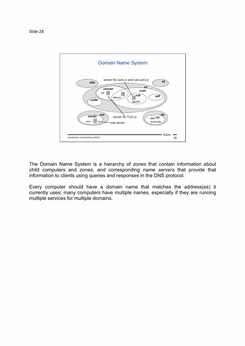
The Domain Name System is a hierarchy of zones that contain information about child computers and zones, and corresponding name servers that provide that information to clients using queries and responses in the DNS protocol. Every computer should have a domain name that matches the address(es) it currently uses; many computers have multiple names, especially if they are running multiple services for multiple domains.
Slide 29
SISALIntroduction to Networking (2020) 29
Domain administration
• Top-level domains (administered by ICANN):
– technical (arpa)
– groups by categories (com, org, edu, mil, gov, net) later extended (info, biz, aero, ...)
– ISO country codes (cz, sk, ...) and some exceptions (uk, eu); countries with interesting names (nu, tv) sell names
– internationalized codes ( = .xn--fiqs8s, )
– currently even private TLDs are allowed
• TLD .cz:
– administered by CZ.NIC (ISP corporation)
– no structure, circa 3/4 mil. names under .cz
– no support for localized names (IDN)
• SLDs and lower level domains:
– administered by owner (ms.[mff.[cuni.cz]])
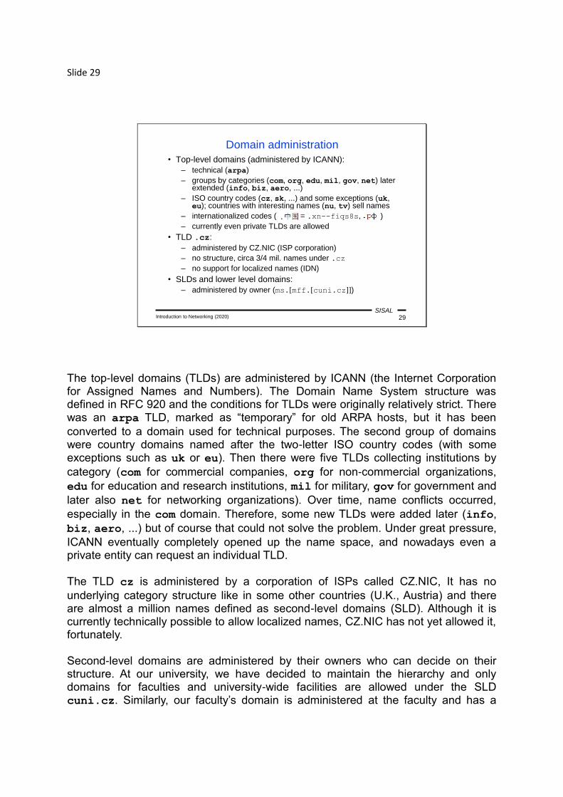
The top-level domains (TLDs) are administered by ICANN (the Internet Corporation for Assigned Names and Numbers). The Domain Name System structure was defined in RFC 920 and the conditions for TLDs were originally relatively strict. There was an arpa TLD, marked as “temporary” for old ARPA hosts, but it has been
converted to a domain used for technical purposes. The second group of domains were country domains named after the two-letter ISO country codes (with some exceptions such as uk or eu). Then there were five TLDs collecting institutions by
category (com for commercial companies, org for non-commercial organizations,
edu for education and research institutions, mil for military, gov for government and
later also net for networking organizations). Over time, name conflicts occurred,
especially in the com domain. Therefore, some new TLDs were added later (info,
biz, aero, ...) but of course that could not solve the problem. Under great pressure,
ICANN eventually completely opened up the name space, and nowadays even a private entity can request an individual TLD. The TLD cz is administered by a corporation of ISPs called CZ.NIC, It has no
underlying category structure like in some other countries (U.K., Austria) and there are almost a million names defined as second-level domains (SLD). Although it is currently technically possible to allow localized names, CZ.NIC has not yet allowed it, fortunately. Second-level domains are administered by their owners who can decide on their structure. At our university, we have decided to maintain the hierarchy and only domains for faculties and university-wide facilities are allowed under the SLD cuni.cz. Similarly, our faculty’s domain is administered at the faculty and has a

structure according to departments and buildings (so the ms domain name is an
abbreviation of “Malá Strana”).

Slide 30
SISALIntroduction to Networking (2020) 30
IP addresses
• Every end node in TCP/IP network must have an IP address
• Current versions:
– IPv4: 4 bytes (e.g. 195.113.19.71)
– IPv6: 16 bytes (e.g. 2001:718:1e03:a01::1)
• Address block assignment:
– public addresses for network is assigned by its ISP
– LAN can use private addresses, unreachable from the internet (security vs. interoperability), address translation (NAT)
• Host address assignment:
– method (fixed vs. dynamic, free vs. limited) is defined by LAN administration
– even for private addresses, exception: link-local addresses
In order to communicate on a TCP/IP network, each end node must have an IP address. As already mentioned, we currently use two versions of the protocol/address. Version 4 which is still dominant in the Czech Republic, has addresses that are 4 bytes long and the common form of their notation is the so-called dotted decimal form. The newer version 6 expanded the address size to 16 bytes and the commonly used format for these addresses is hexadecimal notation in double-byte blocks separated by colons. Due to the large number of zeros in these addresses, the longest series of zero blocks in any address can be replaced by “::” notation. Every address has a prefix defining a network to which the address belongs. The assignment of these network addresses, or address blocks, must meet certain conditions: • Blocks of addresses that should be able to communicate directly with the rest of
the world, so-called public addresses, are assigned to the network administrator by an ISP (or other authority) that connects the network to the Internet.
• For internal use, a network administrator may choose to use one or more private address blocks. They are inaccessible from the Internet (which increases security but complicates interoperability) and in order to enable hosts to access resources on the Internet, a router at the perimeter of the local network must use Network Address Translation (NAT).
A method of assigning addresses to hosts must be chosen by the network administrator and all hosts must follow these rules. The assignment can be static (each node has a predefined IP address) or dynamic (an address is assigned on demand), free (any host can join) or restricted (hosts must authenticate to connect). These rules apply even for private addresses. The only exception are so-called link-

local addresses – they are freely chosen by the host software (with a risk of duplicate address collisions) and they allow communication only within a directly connected network (and only if some other hosts also use a link-local address).
Slide 31
SISALIntroduction to Networking (2020) 31
Port, socket
• Port
... 16bit integer identifying one end of the communication channel - an application, or a process responsible for incoming data processing
– destination-port must be known by clients, usually it is one of so-called well-known services (formerly < 1024)
– source-port is assigned by the originator's OS from unused port numbers (generic port)
• Socket
... one end of the communication channel between the client and the server
… identification (“address”) of the channel end<IP address, port>
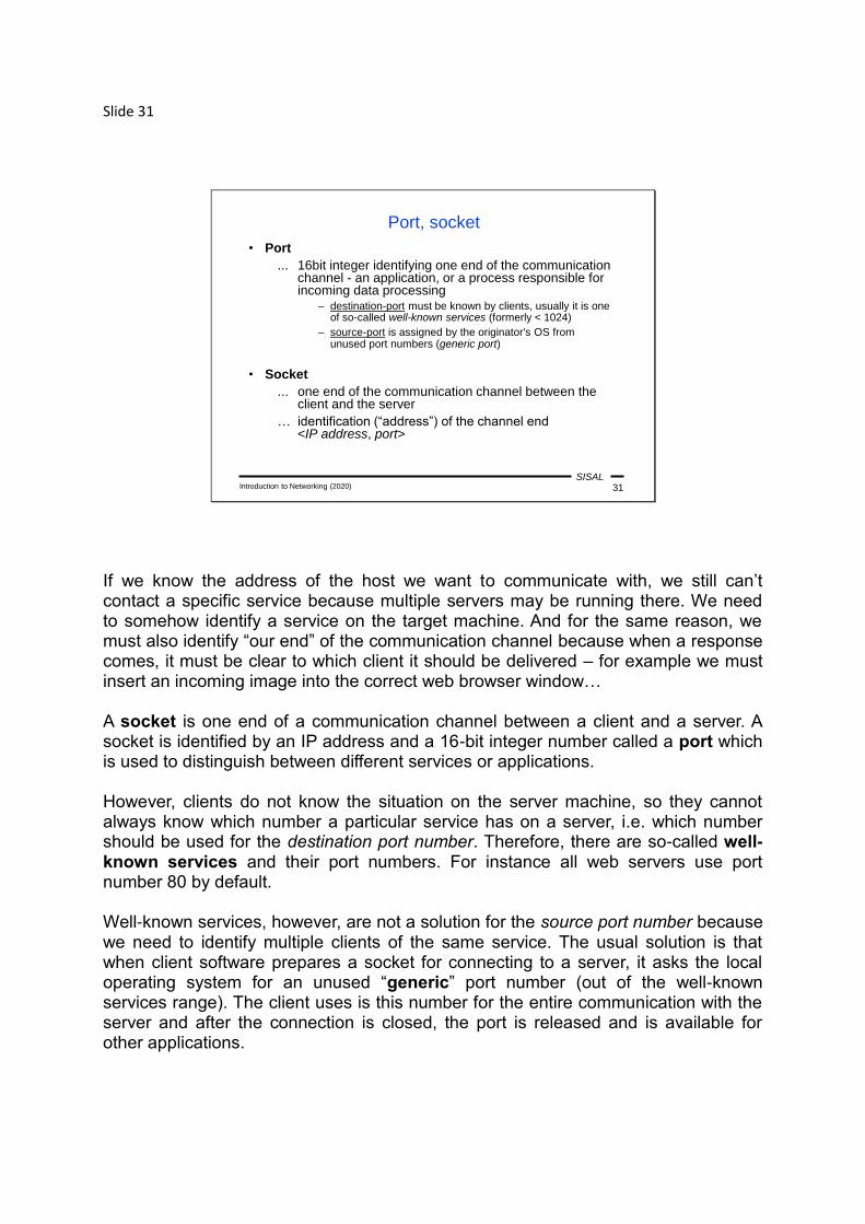
If we know the address of the host we want to communicate with, we still can’t contact a specific service because multiple servers may be running there. We need to somehow identify a service on the target machine. And for the same reason, we must also identify “our end” of the communication channel because when a response comes, it must be clear to which client it should be delivered – for example we must insert an incoming image into the correct web browser window… A socket is one end of a communication channel between a client and a server. A socket is identified by an IP address and a 16-bit integer number called a port which is used to distinguish between different services or applications. However, clients do not know the situation on the server machine, so they cannot always know which number a particular service has on a server, i.e. which number should be used for the destination port number. Therefore, there are so-called well-known services and their port numbers. For instance all web servers use port number 80 by default. Well-known services, however, are not a solution for the source port number because we need to identify multiple clients of the same service. The usual solution is that when client software prepares a socket for connecting to a server, it asks the local operating system for an unused “generic” port number (out of the well-known services range). The client uses is this number for the entire communication with the server and after the connection is closed, the port is released and is available for other applications.

From a mathematical point of view, the unique identification of a TCP/IP connection is an ordered quintuple <source IP address, source port, destination IP address, destination port, transport layer protocol type>. This fact has two consequences: • Two different application channels between two computers must differ at least in
the source port. • The same port numbers can be used for two different communication channels as
long as they do not use the same transport layer protocol.

Slide 32
SISALIntroduction to Networking (2020) 32
Well-known services examples
• 21/TCP: FTP - File Transfer Protocol(file transfer)
• 22/TCP: SSH - Secure Shell(remote logging and file transfer)
• 25/TCP: SMTP - Simple Mail Transfer Protocol(electronic mail transfer)
• 53/*: DNS – Domain Name System(conversion between IP addresses and names)
• 80,443/TCP: HTTP - HyperText Transfer Protocol(transfer of web pages)
• 5060,5061/*: SIP - Session Initiation Protocol(VoIP, IP telephony)
Examples of port numbers on this slide are basic networking literacy, except perhaps for the last bullet which only documents that some well-known services nowadays do not fall in the range from 1 to 1023... Well-known port numbers are usually reserved for both TCP and UDP even if a particular application protocol uses only one of these transport protocols. HTTP uses port 80 for unencrypted and port 443 for encrypted connections. SIP uses different ports for different types of messages.

Slide 33
SISALIntroduction to Networking (2020) 33
Network address translation (NAT)
• General principle: a local network with private addresses using for outside traffic public ones (or other private ones)
• Other term: IP masquerading
• Implementation and terminology can slightly differ in details
1999
2000 10.1.1.1 2345
10.1.1.1 3.3.3.3 2345 80 1.0.0.1 3.3.3.3 2000 80
1.0.0.1
3.3.3.3 1.0.0.1 80 2000
10.1.1.1 2345
3.3.3.3 10.1.1.1 80 2345
The concept of ports plays a very important role in NAT. Hosts with a private address cannot communicate directly with the world outside the local network because an external host has no idea how to route packets when sending a response. A common principle of NAT is that when a host establishes a connection to a server, the router at the perimeter of the private network modifies the content of the packet so that the external host can respond. The router stores the socket address (the IP address and port) of the incoming request and replaces it in the packet by its own external address and a port, currently not used at the router. So, when sending a response, the external host uses this translated socket address for the delivery. When the response arrives at the router, it looks for the appropriate original socket address (according to the destination port used by the external host), changes the destination information back to the original data (the IP address and port from the request) and delivers the response to the client.
Slide 34
SISALIntroduction to Networking (2020) 34
Services addressing
• Uniform Resource Identifier (URI, RFC 3986)
– unified resource reference system (HTML links)
– one client can use various access methods (FTP in WWW)
– former classification: URL (location), URN (name)
URI = scheme:[//] authority [path] [?query] [#fragment]
authority = [login[:password]@]address[:port]
e.g.: ftp://sunsite.mff.cuni.cz/Net/RFC
http://1.2.3.4:8080/q?ID=123#Local
mailto:[email protected]
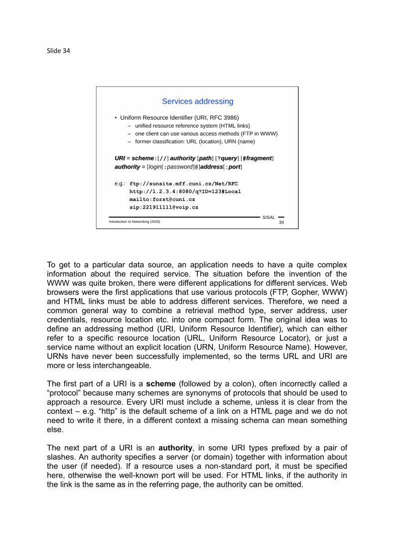
To get to a particular data source, an application needs to have a quite complex information about the required service. The situation before the invention of the WWW was quite broken, there were different applications for different services. Web browsers were the first applications that use various protocols (FTP, Gopher, WWW) and HTML links must be able to address different services. Therefore, we need a common general way to combine a retrieval method type, server address, user credentials, resource location etc. into one compact form. The original idea was to define an addressing method (URI, Uniform Resource Identifier), which can either refer to a specific resource location (URL, Uniform Resource Locator), or just a service name without an explicit location (URN, Uniform Resource Name). However, URNs have never been successfully implemented, so the terms URL and URI are more or less interchangeable. The first part of a URI is a scheme (followed by a colon), often incorrectly called a “protocol” because many schemes are synonyms of protocols that should be used to approach a resource. Every URI must include a scheme, unless it is clear from the context – e.g. “http” is the default scheme of a link on a HTML page and we do not need to write it there, in a different context a missing schema can mean something else. The next part of a URI is an authority, in some URI types prefixed by a pair of slashes. An authority specifies a server (or domain) together with information about the user (if needed). If a resource uses a non-standard port, it must be specified here, otherwise the well-known port will be used. For HTML links, if the authority in the link is the same as in the referring page, the authority can be omitted.

Many URI schemes contain a path to the requested resource on the server. The path format is similar to paths in filesystems (just using slashes to separate directory names) and the path often actually corresponds to the page’s actual location on the server’s filesystem. For HTML links, if the authority is omitted, a relative path anchored in the directory of the referring page can be used, similarly to how a relative path is used in a filesystem. Some URI schemes may contain additional URI parameters used to more precisely specify a request; e.g. an HTTP URI may contain a query (with e.g. data from an HTML form) or a fragment (the identifier of the location of an exact point inside the page that the browser should focus on).
Slide 35
SISALIntroduction to Networking (2020) 35
Data flow in TCP/IP
link.
net
transp.
link.
net
link.
net
transp.
MAC address
IP address
app. app.
http://www.mff.cuni.cz URI (URL)
application(WWWclient)
application(WWWserver)
IP addr.+port
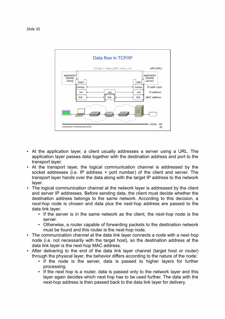
• At the application layer, a client usually addresses a server using a URL. The application layer passes data together with the destination address and port to the transport layer.
• At the transport layer, the logical communication channel is addressed by the socket addresses (i.e. IP address + port number) of the client and server. The transport layer hands over the data along with the target IP address to the network layer.
• The logical communication channel at the network layer is addressed by the client and server IP addresses. Before sending data, the client must decide whether the destination address belongs to the same network. According to this decision, a next-hop node is chosen and data plus the next-hop address are passed to the data link layer.
• If the server is in the same network as the client, the next-hop node is the server.
• Otherwise, a router capable of forwarding packets to the destination network must be found and this router is the next-hop node.
• The communication channel at the data link layer connects a node with a next-hop node (i.e. not necessarily with the target host), so the destination address at the data link layer is the next-hop MAC address.
• After delivering to the end of the data link layer channel (target host or router) through the physical layer, the behavior differs according to the nature of the node:
• If the node is the server, data is passed to higher layers for further processing.
• If the next hop is a router, data is passed only to the network layer and this layer again decides which next hop has to be used further. The data with the next-hop address is then passed back to the data link layer for delivery.
Slide 36
SISALIntroduction to Networking (2020) 36
interface
Multiplexing, encapsulation
cmd datafunction( , )
layer n
layer n - 1
bodyheader
protocol
recipientsender
PDUn-1
IDU
PDUn
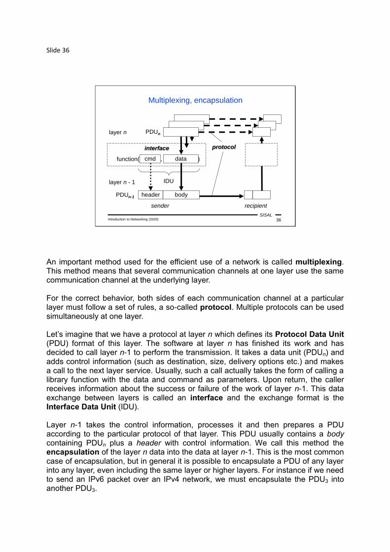
An important method used for the efficient use of a network is called multiplexing. This method means that several communication channels at one layer use the same communication channel at the underlying layer. For the correct behavior, both sides of each communication channel at a particular layer must follow a set of rules, a so-called protocol. Multiple protocols can be used simultaneously at one layer. Let’s imagine that we have a protocol at layer n which defines its Protocol Data Unit (PDU) format of this layer. The software at layer n has finished its work and has decided to call layer n-1 to perform the transmission. It takes a data unit (PDUn) and adds control information (such as destination, size, delivery options etc.) and makes a call to the next layer service. Usually, such a call actually takes the form of calling a library function with the data and command as parameters. Upon return, the caller receives information about the success or failure of the work of layer n-1. This data exchange between layers is called an interface and the exchange format is the Interface Data Unit (IDU). Layer n-1 takes the control information, processes it and then prepares a PDU according to the particular protocol of that layer. This PDU usually contains a body containing PDUn plus a header with control information. We call this method the encapsulation of the layer n data into the data at layer n-1. This is the most common case of encapsulation, but in general it is possible to encapsulate a PDU of any layer into any layer, even including the same layer or higher layers. For instance if we need to send an IPv6 packet over an IPv4 network, we must encapsulate the PDU3 into another PDU3.

The header must also contain an identifier of the layer n because decapsulation and demultiplexing must be performed on the recipient side. Layer n-1 checks the control information and passes the data (body) to appropriate software at layer n.

Slide 37
SISALIntroduction to Networking (2020) 37
packet
PDU types in TCP/IP
stream, messageOSI 5-7
dataOSI 4
OSI 3
OSI 2 FCS
...
frame
...
OSI 1
PDU
PDU
PDU
MACdst typ
segmentIPsrc IPdst typ
MACsrc
portsrc portdst #
Let’s look at how multiplexing and encapsulation work in the TCP/IP protocol suite. The application layer sends either separate messages (in connectionless mode), or a stream of data (in connection-oriented mode). It passes the data together with the target socket address to the appropriate protocol at the transport layer. If TCP is used, it takes the data from the stream and breaks (segments) it into smaller blocks and prepends a header containing, among other information, the source and destination port numbers and an “offset” into the stream so that the data can be sorted and reassembled upon delivery. UDP has much simpler work to do, it just prepends a header with port numbers to each message. The PDU4 is then passed to the network layer along with the destination IP address. The network layer takes a segment and prepends a header with the source and destination IP addresses and the transport layer protocol number, creating a packet. It then takes the destination address and checks if the packet can be delivered directly to the destination host or if a next-hop router must be used for forwarding. The packet, along with the data link layer destination node address is passed to the data link layer. Warning: be careful when talking about “packets”, be sure to clearly indicate whether you mean a well-defined PDU3, or a loose term of “packet switching” networking mode. The data link layer takes a packet and prepends a header with the destination and source MAC addresses and the network layer protocol number. Since this is the last “software” layer before the data is passed to the “hardware” (the physical layer), we

need some way to check whether the data has been transferred correctly. Therefore, the data link layer PDU (called a frame) contains also a suffix, the so-called Frame Check Sequence (FCS), the value of which is calculated from the contents of the rest of the frame. The last step is to pass the frame to the physical layer to be transferred. Upon the delivery to the destination node, the physical layer decodes the data and passes it to the data link layer. The data link layer recalculates the value of the FCS and checks whether it is equal to the value stored in the frame. It also checks the destination MAC address to see whether the data belongs to this node. The decapsulated packet is then passed to the network layer software chosen according to the network layer protocol code stored in the header. The network layer checks the destination IP address and passes the decapsulated segment to the appropriate transport layer software. The work of the transport layer depends on the protocol used. In the UDP case, the message is simply delivered to the application. In the TCP case, the segment is saved and the entire data block will be delivered to the application after all segments have been received.

Slide 38
SISALIntroduction to Networking (2020) 38
Summary 2
• Describe the differences between TCP, UDP and IP.
• Which addresses are used at the application, transport, network, data link and physical layer?
• What is the difference between the client-server and peer-to-peer application mode?
• How are domain names administered?
• How are IP addresses assigned?
• What is the meaning and principle of NAT?
• What is multiplexing and encapsulation?