lathe cnc controller - lubi electronics · table of contents i table of contents 1 main features of...
TRANSCRIPT
Lathe CNC Controller Manual
Ver:Jan. , 2014
HUST Automation Inc. No. 80 Kon Yei Road, Toufen, Miaoli, Taiwan
Tel: 886-37-623242
Fax: 886-37- 623241


TABLE OF CONTENTS
I
TABLE OF CONTENTS
1 MAIN FEATURES OF LATHE CNC CONTROLLER 1-1
2 INSTRUCTION 2-1
2.1 Basic Instructions 2-1
Power-On Display 2-1
Standby Display 2-1
Auto Mode Display 2-2
MDI Mode Display 2-3
Home Origin Mode Display 2-3
Jog Mode display 2-4
Edit Mode display 2-5
Program Mode Display 2-6
I/O Mode Display 2-8
Tool Compensation Display 2-9
Graphic mode 2-15
2.2 Program Edition 2-16
2.2.1 Programming Introduction 2-16
2.2.1.1 Part Program 2-16
2.2.1.2 Methods Of Programming 2-16
2.2.1.3 The Composition of A Part Program 2-18
2.2.1.4 Coordinate System 2-20
2.2.1.5 Control Range 2-25
2.2.2 Program Editing 2-26
2.2.2.1 Program Selection 2-26
2.2.2.2 New Program Editing 2-27
2.2.2.3 Program Revision 2-30
2.2.2.4 Rules for Numerical Input 2-33
2.2.2.5 Notes on Program Edit 2-34
3 G/M Codes 3-1
3.1 Command codes 3-1
3.2 Positioning, G00 3-4
3.3 Linear Interpolation, G01 3-5

HUST CNC H4D-T MANUAL
II
3.4 Circular Interpolation, G02 & G03 3-7
3.5 Dwell, G04 3-11
3.6 Parabolic Cutting, G05 3-12
3.7 Exact Stop Check, G09. G61, G62 3-15
3.8 Spindle Positioning Command, G15 3-16
3.9 Cylindrical Plane, G16 3-16
3.10 Plane Setup, G17~G19 3-20
3.11 Automatic Reference Position Return, G28 3-23
3.12 Retrun From Reference Position, G29 3-24
3.13 2nd Reference Position Return, G30 3-25
3.14 Thread Cutting, G32 3-26
3.15 G33 Tapping Cutting Canned Cycle 3-30
3.16 G34 Variable Lead Thread Cutting 3-31
3.17 Canned Cycle Functions 3-35
3.17.1 Single Cutting Canned Cycle, G90, G92, G94 3-35
3.17.2 Compound Canned Cycle Functions, G70~G76 3-41
3.18 G50 Coordinate System & Spindle clamp speed setting 3-59
3.19 Constant Surface Speed Control ON, G96 3-60
3.20 Constant surface Speed Control OFF, G97 3-61
3.21 Feed-Rate Setting, G98. G99 3-61
3.22 Inch/Metric Measurement Mode, G20, G21 3-62
3.23 Deep Hole Driling Cycle (Z axis), G83, G80 3-62
3.24 Tapping Cycle, G84, G80 3-63
3.25 Auxiliary Functions, M-code, S-code 3-65
3.26 Subprogram 3-67
3.27 Tool Radius Compensation 3-68
3.27.1 Total Offset Compensation Setting and Cancellation 3-68
3.27.2 Tool-Tip Radius and Direction of Fictitious Tool-Tip, G40~G42 3-70
3.27.3 Interference Check 3-90
3.27.4 Notes of Tool Radius Compensation 3-93
3.28 Coordinate System 3-95
3.28.1 Local Coordinate System Setting, G52 3-95
3.28.2 Basic Machine Coordinate System, G53 3-96
3.28.3 Work Coordinate System, G54~G59 3-97
3.29 Corner Chamfer(,C_), round-angle chamfer (,R_) functions 3-100
3.29.1 Chamfer (,C_) 3-100
3.29.2 Round-angle chamfer (,R_) 3-102
3.30 Liner angle function (,A_) 3-103
3.31 Geometry function command 3-105
TABLE OF CONTENTS
III
3.32 Automatic calculation of Line-Arc Intersection Poing 3-108
4 MCM PARAMETERS 4-1
4.1 MCM Parameter 4-1
4.1.1 Basic Description 4-1
4.1.2 MCM Parameters 4-1
4.2 Description of Parameters 4-5
5 CONNECTIONS 5-1
5.1 System Configuration Descriptions 5-1
5.2 System Installation 5-2
5.2.1 Operating Environment 5-2
5.2.2 Considerations for the design of control panel 5-2
5.2.3 Internal temperature Design 5-3
5.2.4 H4D-T External Dimensions 5-4
5.2.5 H4D-T Accessories Dimensions 5-6
5.3 Connector Type 5-8
5.4 Connector Name 5-8
5.5 Connector Pin-out Definiton 5-9
5.5.1 G31 Input Control Singnals 5-12
5.5.2 Axial Control, Pin Assignment and Wiring 5-13
5.5.3 Wiring of Manual Pulse Generator (MPG) 5-14
5.5.4 Wiring of Spindle Control 5-15
5.5.5 I/O Wiring 5-17
5.5.6 I/O Wiring Schematic 5-19
5.5.7 Wiring of System AC Power Supply 5-25
5.5.8 Servo on Wiring Examples 5-26
6 ERROR MESSAGES 6-1
7 MCM (Machine Constant) PARAMETERS 7-1
7.1 Description of MCM Machine Constants 7-23

HUST CNC H4D-T MANUAL
IV
8 APPENDIX 8-1
Input Arrangement 8-1
Output Arrangement 8-2
M-Code Versus I/O 8-2
Compound Canned Cycle Parameters 8-3
PLC Parameters 8-3

1 MAIN FEATURES
1 - 1
1 MAIN FEATURES OF LATHE CNC CONTROLLER
Controlled Axis: X, Z and Spindle Encoder Feedback
Program Designed by CAD/CAM on PC. Program input and DNC on-line
execution from PC through RS232C interface.
Memory Capacity for CNC main board - 1024k.
Battery Backup for CNC program storage in case of power-off.
Backlash error compensation for worn lead screw.
Provide 40 sets of tool length offset.
Self-designed MACRO Program.
Tool feed rate can be a millimeter per minute or a millimeter each turn.
Single block and continuous commands.
Option Skip functions.
Option Stop and Feed hold functions.
Simultaneous use of absolute and incremental coordinate in the program.
Self-diagnostic and error signaling function.
Direct use of “ R”, “ I” and “ J” incremental value for radius in circular
cutting.
MPG hand-wheel test and collision free function for cutting product at the
speed controller by MPG.
Equipped with 24 standard programmable inputs and 16 outputs.
This operator’s manual includes program editing, G/M code, parameter settings,
connections and maintenance (plus warn descriptions) with examples and
explanations for each command instruction.
If there are any problems in application, please fill out a problem sheet
indicating the natures of the problem. Send it by either fax or mail. We will
respond to you as soon as possible.

HUST CNC H4D-T MANUAL
1 - 2
2 INSTRUCTION
2 - 1
2 INSTRUCTION
2.1 Basic Instructions
Operating Diagrams
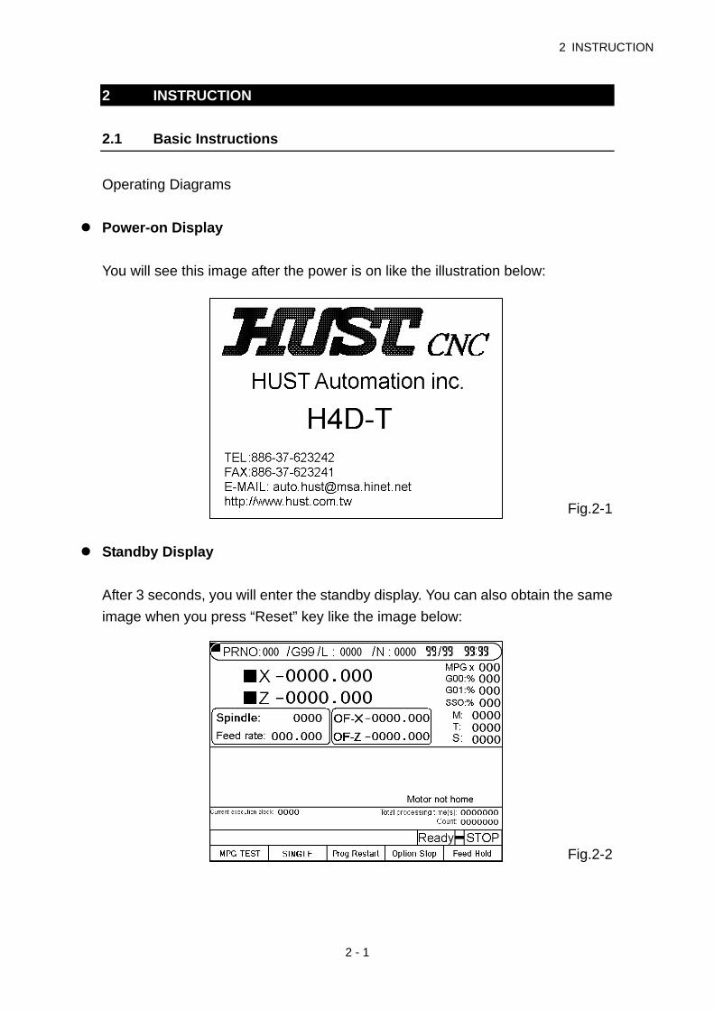
Power-on Display
You will see this image after the power is on like the illustration below:
Fig.2-1
Standby Display
After 3 seconds, you will enter the standby display. You can also obtain the same
image when you press “Reset” key like the image below:
Fig.2-2

HUST CNC H4D-T MANUAL
2 - 2
Auto Mode Display
Press key “ Auto/ MDI” to enter the auto mode, the display is shown below:
Fig.2-3
Soft keys under the auto mode:
1. Program Feed-Hold: only valid during the program operation.
In the program operation, press the key and the program will stop
immediately. You can continue operating the program by press this soft key
again or CYCST key.
2. Single Step Execution: users can select the function any time without being
limited in the state of operation or stop. This function can only carry one
step by each key press of restart instead of executing the whole program
continuously.
3. Program Restart: only can be selected before the program execution.
When the program restart is being selected, it will continue the task from
the previous single block where it stopped. Users can search the stopped
single block or reset the block in the editing display.
4. MPG - TEST: users can select the function any time without being limited in
the state of operation or stop. When the function is being selected, the
movement of all the axis in the program can only be controlled by MPG. If
there is no input of MPG, the axis will stop moving. The users can also use
manual key 『X+』、『Z-』press to replace MPG.
5. Option Stop: only can be selected before the program execution. When
option stop is being selected, M01 commend in the program will be
considered as a stop commend. It is meaningless if M01 is not selected.
Part numbers: each execution to M15 will add on one and execution to M16 will
return to zero. If users need to return to zero manually, please press the “0” key

2 INSTRUCTION
2 - 3
twice immediately to return zero.
※ When part numbers reach to the parameter counting limit, O13 will output.
Part time: show the current executing time. After each program end or stop,
it will automatically return to zero when it restarts.
MDI Mode Display
Press 『 Auto/ MDI』key twice to enter the MDI mode, the display is shown
below:
Fig.2-4
Home Origin Mode Display
Press 『JOG/HOME』key twice to enter the home origin mode, the display is
shown below:
H4D-T display
Fig. 2-5

HUST CNC H4D-T MANUAL
2 - 4
Methods for returning the origin:
1. Select the axis: there are some ways to select the axis. You can either
press the English letter “ X ”, “ Z “ on the right of the screen directly or press
the key button” X+’, “X-“, “Z+”, “Z-“ to make your selection.
2. Press” CYCST” key
Note: X and Z- axis will be displayed as reversal colors on the screen once they
are selected. The initialized screen display is set Z-axis for its starting of
origin mode.
Jog Mode display
Press『JOG/HOME』key to enter jog mode, the display is shown below:
Fig.2-6
There are several functions under the jog mode:
1. Axis positioning:(Three types of positioning)
a. Manual jog: select the axis (see the note of home origin mode for
reference) to turn the jog. The jog will be in valid if the axis is not
selected.
b. Continuous movement: (Single step function is not on)
Continuously press “X+” key and X-axis will do positive movement,
X-axis will do negative movement. Z-axis is followed the same way.
c. Move single step:
Select your desired distance for each single step such as
0.001,0.01,0.1,1 and press X+, X-, Z+,Z-. The system will follow the
selection to make the step.
Note: Press the key once more it returns back to continue jog mode.

2 INSTRUCTION
2 - 5
2. Manual Switch:
a. Spindle: Clockwise, Counter Clockwise, Stop.
b. Coolant: Press on and off key
c. Lubricant: Press the key and it will be provided after 1 second.
LED is the indicator for the operation.
Edit Mode display
Press “Edit/PRNO” to enter the edit mode, the display is shown below:
Fig.2-7
This screen mode can be edited directly (Please see the edit chapter for details).
a. Set-Re.N: In program edit mode, use cursor up and down to assign the
single command, press the key, then return the AUTO mode display. It will
execute the assign program when press the『RESTART』key .
b. Last-N: When stop the program(If press the Reset、EM-STOP key …),
press this key can find the last executed single program.
HUST CNC H4D-T MANUAL
2 - 6
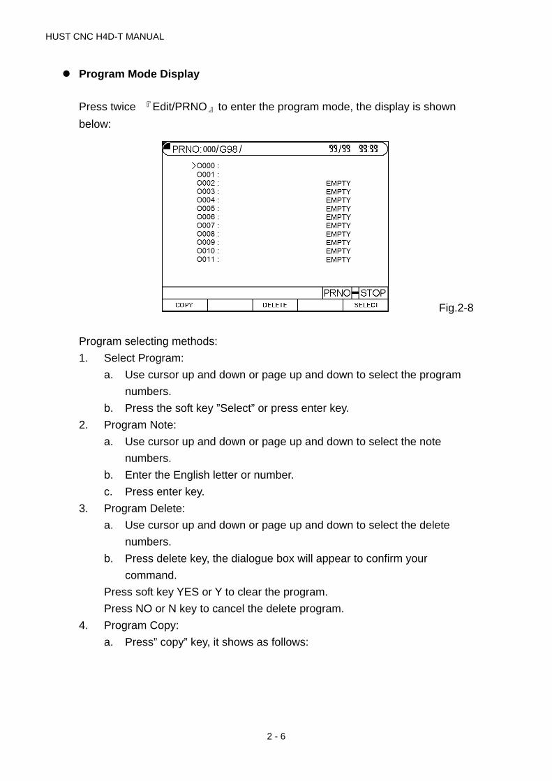
Program Mode Display
Press twice 『Edit/PRNO』to enter the program mode, the display is shown
below:
Fig.2-8
Program selecting methods:
1. Select Program:
a. Use cursor up and down or page up and down to select the program
numbers.
b. Press the soft key ”Select” or press enter key.
2. Program Note:
a. Use cursor up and down or page up and down to select the note
numbers.
b. Enter the English letter or number.
c. Press enter key.
3. Program Delete:
a. Use cursor up and down or page up and down to select the delete
numbers.
b. Press delete key, the dialogue box will appear to confirm your
command.
Press soft key YES or Y to clear the program.
Press NO or N key to cancel the delete program.
4. Program Copy:
a. Press” copy” key, it shows as follows:

2 INSTRUCTION
2 - 7
Fig.2-9
b. Use cursor up and down or page up and down to point at the source
program numbers.
c. Press Source key
d. Use cursor up and down or page up and down to select the purpose
numbers.
e. Press purpose key
f. After confirmation for both source and purpose of program numbers,
and press executing (Exec.) key. The copy is complete.
I/O Mode Display
Press twice 『I/O/ MCM』key to enter I/O mode, the display is shown below:
Fig.2-10
Under this mode it can check the input status of the controller. (Color reversion
shows inputting.) Press output soft key, it will cut to the output status display like
the figure below:

HUST CNC H4D-T MANUAL
2 - 8
Fig.2-11
Under this mode it can check the output status of controller. (Color reversion
shows outputting.) Press input soft key, it again returns back to input status
screen.
IOCSA Monitor : Input page press F5 key
Fig.2-12
Tool Compensation Display
Press 『TOOL.Offset』to enter offset & wear compensation directly in the tool
compensation mode.
Press
to change the
status

2 INSTRUCTION
2 - 9
Fig.2-13
Users can utilize the soft key to switch three different screen displays such as
tool wear, offset compensations and parameters under this mode.
※ Note:Press the key the page can be changed.
1. Ways for parameter setting in tool offset compensation are as follows:
a. Utilize the cursors to move to the revising parameter.
b. Enter numbers.
c. Press enter key.
2. Tool wear compensation display is below:
Fig.2-14
Tool offset compensation setting are as follows:
a. Utilized the cursors to move to the revising parameter.
b. Enter numbers.
c. Press enter key.

HUST CNC H4D-T MANUAL
2 - 10
3. Parameters display is followed:
Fig.2-15
Fig.2-16
4. When the error occurs, the system will automatically switch to the error
dialogue box or press the D1 key for error messages.
Fig. 2-17
2 INSTRUCTION
2 - 11
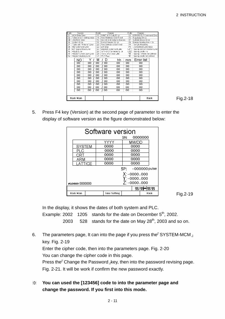
Fig.2-18
5. Press F4 key (Version) at the second page of parameter to enter the
display of software version as the figure demonstrated below:
Fig.2-19
In the display, it shows the dates of both system and PLC.
Example: 2002 1205 stands for the date on December 5th, 2002.
2003 528 stands for the date on May 28th, 2003 and so on.
6. The parameters page, It can into the page if you press the『SYSTEM-MCM』
key. Fig. 2-19
Enter the cipher code, then into the parameters page. Fig. 2-20
You can change the cipher code in this page.
Press the『Change the Password』key, then into the password revising page.
Fig. 2-21. It will be work if confirm the new password exactly.
※ You can used the [123456] code to into the parameter page and
change the password. If you first into this mode.

HUST CNC H4D-T MANUAL
2 - 12
Fig.2-20
Fig.2-21
Fig.2-22

2 INSTRUCTION
2 - 13
※ press the key 『TOOL.RADIUS』 to enter the work origin setting: Note that
this is only valid in the state of home origin.
Work Origin setting(1) is demonstrated below:
Fig.2-23
Note: When mount the Tool above the Work-piece, it means the Upper Holder
(Rear Holder); when mounting under the Work-piece, it means the Lower
Holder (Front Holder). The system parameters can be used to set the
Holder type, for example, X-Axis means the direction when Tool is leaving
the Work-piece (refer to Fig. 2-22). If the Tool is located at “Negative X
Direction” at the center of the Work-piece, then negative value should be
entered for the diameter (as per Example 2).
Tool Calibration Step:
1. Clamp the Work-piece securely (clamp with Pedal Switch or Manual Chuck
key).
2. Set the group number.
3. Write in X-Axis position.
a. Move the Tool with Hand Wheel for accepting OD machining. Before
the entire Tool leaves the machining coordinates, press the “X Tool
Offset” key and at this time, the system will save the machine
coordinates of X-Axis in the X-Axis position.
b. Move the Tool away with Hand Wheel. After measuring the actual
Work-piece diameter, enter the diameter of X-Axis.
c. Press “X Tool Offset” key again and the Controller will calculate
automatically for writing the result in the designated Tool length offset
parameter.

HUST CNC H4D-T MANUAL
2 - 14
4. Write in Z-Axis Position:
a. Move the Tool with the Hand Wheel for accepting end face machining.
Before the entire Tool leaves the machining coordinates, press “Z Tool
Offset” key and at this time, the system will save the machine
coordinates of X-Axis in the Z-Axis position.
b. Enter the Work-piece length. To use the machining end face as the
working Home Position for Z-Axis, set the length as “0”.
c. Press “Z Tool Offset” key again and the Controller will calculate
automatically for writing the result in the designated Tool length offset
parameter.
Example 1:
1. If the Tool has not entirely left the machining coordinates, the machine
coordinates will be (13.000, 13.638.)
2. Enter diameter as 20.000mm (diameter program setting and the Tool is
located at the X position direction at the centerline of the Work-piece).
3. Enter the length as 0.000mm (the machining end face will be the working
Home Position of Z-Axis).
4. Press “F3-X Tool Offset” and “F5-Z Tool Offset” respectively.
5. The X, Z coordinates saved for the Tool setting screen will be (6.000 and
13.638) respectively. Under Tool length offset screen, the X, Z coordinates
of this group will be (6.000, 13.638.)
Example 2:
1. If the Tool has not entirely left the machining coordinates, the machine
coordinates will be (-15.400, 12.166.)
2. Enter diameter as -20.000mm (radius program design and the Tool is
located at X negative direction at the centerline of the Work-piece).
3. Enter the length as 10.000mm (the machining end face will be the working
Home Position of Z-Axis).
4. Press “F3-X Tool Offset” and “F5-Z Tool Offset” respectively.
The X, Z coordinates saved for the Tool setting screen will be (-5.400 and 2.166)
respectively. Under Tool length offset screen, the X, Z coordinates of this group
will be (-5.400, 2.166.)

2 INSTRUCTION
2 - 15
Graphic Mode Display
AUTO mode press the key “ GRAPH “ to enter the graph mode display as
follows:
Fig. 2-24
1. Display Percentage: With Page Up/Page Down page key, you may adjust
the displayed percentage of the working route flexibly in dynamic way.
2. Display Position: With Up/Down/Left/Right Direction Cursor key, you may
adjust the graphical Home Position displayed in the screen or adjust the
draft Home Position by letter keys in a quicker manner.
I-Screen Upper Left; J-Screen Middle Up; K-Screen Upper Right
R-Screen Middle Left; S-Screen Center; T-Screen Middle Right
G-Screen Lower Left; F-Screen Lower Middle; M-Screen Lower Right
3. Coordinate Plane Shift: Letter X-XY Plane, Letter Y-YZ Plane, Letter Z-XZ
Plane.
4. Clear the drafted working route: By pressing “Clear” key, you may erase the
drafted working track from the graph screen.
5. The drafting action will be divided into the the following two types:
“Hands-on Draft”, “Fast Draft”.
Shift Method: Under Draft Mode and before starting the program, press
“Fast” key (once for ON and press again for OFF).
Fast Key Indicator ON “Fast Draft”
Fast Key Indicator OFF “Hand-on Draft”
“Hand-on Draft”: Servo axis displacement command together with M, T
and S codes will be executed.

HUST CNC H4D-T MANUAL
2 - 16
“Fast Draft”: Servo axis will be locked without displacement, but M, T and
S codes will be executed.
Such function is useful for initial working, as the operator can check if the
working route is correctly planned under absolute safe conditions.
2.2 Program Edition
2.2.1 Programming Introduction
2.2.1.1 Part Program
Prior to cutting a machine part by using a CNC cutting tool, a computer program,
called a part program, must be created to describe the shape of the parts, which
is based on some kind of coordinate system. The cutting tool will then follow
these coordinates to do exact cutting. To create a part program, a concise
machining plan is a necessity, which includes the coordinates for the machine
part, coolant, spindle speed, tool type, I/O-bit, etc.. When design a machining
plan, the following factors must be considered:
1. Determine the machining range requirement and select the suitable CNC
machine tool.
2. Determine the work-piece loading method and select the appropriate
cutting tool and the tool holder.
3. Determine the machining sequence and the tool path.
4. Determine the cutting conditions such as spindle speed (S), federate (F),
coolant, etc.
A part program is a group of sequential instructions formulated according to the
machining plan. It can be edited either on a personal computer (PC), then
transmitted to the CNC controller through RS232C interface or directly on the
CNC controller using the editing keys. Lathe can do both. They will be discussed
later.
2.2.1.2 Methods Of Programming
A CNC controller will execute the commands exactly in accordance with the
instructions of the part program. So, the program design is the most important

2 INSTRUCTION
2 - 17
task in the whole CNC machining process. There are two ways to design a CNC
part program and are to be briefly described as bellows:
1. Manual Programming
Manual programming is a process that the whole process is manually done
by hand including the coordinate calculations. It follows this sequence.
Machine part drawing.
Part shape description includes coordinate calculations.
Computer program design includes spindle speed, feed rate, M-code,
etc..
Keying in the program instructions into the CNC controller or
transmitted from PC.
Testing the program.
The coordinate calculation is a simple process if the part shape is
composed of straight lines or 90-degree angles. For curve cutting, however,
the calculation will be more complicate and trigonometry will be required for
correct answers. Once all calculations have been completed, the CNC part
program is written in the formats to be discussed later.
The main disadvantage of manual programming, particularly when
designing for a very complicated part, is time consuming and prone to
making errors. In this case, automatic programming becomes more
advantageous than the manual methods.
2. Automatic Programming
Automatic programming is a process in which the design work included
coordinate calculation that is done by computer. It follows this sequence.
Computer added design for part drawing (CAD)
Computer added manufacturing for CNC part program (CAM)
Transferring program to CNC controller.
Testing the program.
By making use of computer’s high speed calculating capability, program
designer can communicate with the computer in simple language, to describe
the shape, size and cutting sequence of the part. The computer will transfer the
motions to the machine tool into a part program, which is then transferred into
CNC controller through RS232C interface. This process is called CAD/CAM. It is

HUST CNC H4D-T MANUAL
2 - 18
a necessary tool when designing a part program for a 3-D work-piece.
2.2.1.3 The Composition of A Part Program
A complete part program is composed of program blocks, starting with a program
number Oxxx, ended with M2, M30, or M99, and in between with a series of
CNC instructions. A CNC instruction is a command to order the cutting tool to
move from one location to another with the specified speed, or the peripheral
equipment to do some mechanical work. The cutting is done when the cutting
tool moves.
An example of a complete part program containing nine blocks is as follows:
N10 Go X40.000 Z10.000
N20 G00 X30.000 Z5.000
N30 M3 S3000
N40 G1 X10.000 F200
N50
W-5.000
N60 X15.000 Z-10.000
N70 X30.000 W-10.000
N80 G0 X40.000 Z10.000
N90 M5
N100
M2
A block of program can have one to several instructions and it has a general
form as follow. The block sequence number "Nxx" can be omitted. If you do not
key in the block number, Lathe has a special function "Auto-N" to automatically
generate the number for you during or after program editing (see chapter 6). The
program execution starts from top to bottom block and has nothing to do with the
order of block sequence number. Each instruction starts with an English letter
(A~Z), followed by a integer or floating number, depending on what type of
instruction the number is associated with. If the number represents a coordinate,
it can be positive (+) or negative (-).
N-____G____X(U) ____Z(W) ____F____S____T ____M____
N : block sequence

2 INSTRUCTION
2 - 19
G : function command
X, Z : coordinate position command (absolute position command)
U, V : coordinate position command (incremental position command)
F : Feed rate
S : Spindle speed
T : Tool command
M : Auxiliary command (machine control codes)
In general, the program instructions can be divided into four categories.
1. Function command:
G-code. A CNC command to instruct the cutting tool to do an action, such
as straight, circular or thread cut, compound cut, etc.
2. Position command:
X, Z, U, W. A coordinate command to instruct the cutting (Motion command)
tool to stop the cutting action at the location specified -- an end point. The
end point of the current block is the starting point of the next block.
3. Feed-rate command:
F-code. A command to instruct the cutting tool how fast to do the cutting.
4. Auxiliary command:
M, S, T, L, etc. A command to instruct the peripheral equipment to do an
action, such as spindle speed, coolant on/off, program stop, etc.
Note that not every block is composed by these four parts. Some have only one
command. We will have further discussions in chapter 3.
Basic command format (similar with position command):
X-10.000
X : command code
“-“ : positive and negative signs(sign + can be omitted)
10.000 : destination point for tool position
Each command code has a fixed format and a special meaning to the CNC
controller and it must be strictly followed when designing a program. The system
will not accept the command if the format is in error. Otherwise, a machine error
will result. Followings are the command codes that are used in Lathe.

HUST CNC H4D-T MANUAL
2 - 20
F :Feed-rate in mm/min or mm/revolution, a decimal.
G :Function G-code, an integer.
H :Tool offset compensation number.
I :The X-axis component of the arc radius @ the start point, a decimal.
K :The Z-axis component of the arc radius @ the start point, a decimal.
L :Repetition counter, integer.
M :Control code for peripheral machine tool, integer.
N :Program block (sequence) number, integer.
P :Dwell time; subprogram code; or parameter in canned cycles, integer.
Q :Parameter in canned cycles, integer.
R :Arc radius or "R" point in canned cycles, decimal.
S :Spindle speed, integer.
T :Tool commands.
U :Incremental coordinate in X-axis, decimal.
W :Incremental coordinate in Z-axis, decimal.
X :Absolute coordinate in X-axis, decimal.
Z :Absolute coordinate in Z-axis, decimal.
Each serial number of program represents a block. Although it is not necessary
to use it, it is recommended to utilize the serial numbers for program searching.
Lathe has a special function "Auto-N" to automatically generate the number for
you during or after program editing (see chapter 6). The program execution
starts from top to bottom block and has nothing to do with the order of block
sequence number.
Example: N10….…(1) program execution order
N30…….(2)
N20…….(3)
N50…….(4)
N40…….(5)
2.2.1.4 Coordinate System
The machining action of a cutting tool is accomplished when the tool is moving
along a specific path from point A to point B, which represents the shape or the
contour of a machine part. In order for the tool to follow the specific path, a
computer program describing the shape of the machine part must be created
and the shape or the contour is described by the Cartesian coordinate system.

2 INSTRUCTION
2 - 21
Cartesian Coordinate System
Lathe uses the customarily 2-D Cartesian coordinate system as shown in Fig
2-18, with Z-axis being the center of and parallel to the spindle axis and defined
as x=0. The other axis is X-axis and Z=0 can be anywhere along the Z-axis at
some convenient location for coordinate calculation. The intersecting point of the
two axis is the origin, X=0, Z=0. Depending on the location of the cutting tool with
respect to the spindle axis, the sign convention of the coordinate system is
shown in Fig 2-25.
Fig 2-25 Cartesian Coordinate System of CNC Lathe
Fig 2-24 is 3-D system (right-hand rule) with the intersecting point designated as
origin X=Y=Z=0. The direction of normal rotation for each axis is indicated by the
direction of the four fingers when you grab the axis by the right hand with your
thumb pointing to the (+) direction of that axis.
Coordinate of Tool Position Command
The instruction for tool position command in H4D-T series can be in either
absolute coordinate or incremental coordinate as follows:
X, Z : Absolute coordinate command. The cutting tool moves to the position
specified by the absolute coordinate X, Z.
U, W : Incremental coordinate command. The cutting tool moves to the position
with an incremental amount specified by U, W.
Note : Diameter usually stands for X-axis of coordinate in Lathe CNC no matter
it is absolute or incremental.
G0 G0
G0 G0
+Z
+X Tool at the Rear+Z
+X Tool at the Front+Z
M03 CW
M04 CCW

HUST CNC H4D-T MANUAL
2 - 22
Absolute Coordinate
The origin is the reference. The coordinates of all points describing the shape of
the work-piece (machine part) are calculated from the origin. The coordinates
can be positive (+) or negative (-), depending on its relative position with respect
to the origin.
Incremental Coordinate
The coordinates of all points describing the shape of the work-piece (machine
part) are calculated from the end point of the previous block. They are the
amount of coordinate increase from the last point. The incremental coordinates
can be either positive (+) or negative (-), depending on its relative position with
respect to the end point of the previous block. They are positive (+) if the cutting
tool is going in the direction of U, W increment, negative (-), otherwise is in the
direction of U, W decrement.
X, Z, U, W can be mixed in the program. The methods are described below:
Absolute Command:
P0 to P1---G01 X10.000 F0.200
P0 to P2---X24.000 Z30.000
P2 to P3---X32.000 Z10.000
P3 to P4---Z0.000
Fig.2-26 Absolute Command
10
30 38
P
P
P
P
5
1316
Z
X
P
X0. ZO.
2 INSTRUCTION
2 - 23
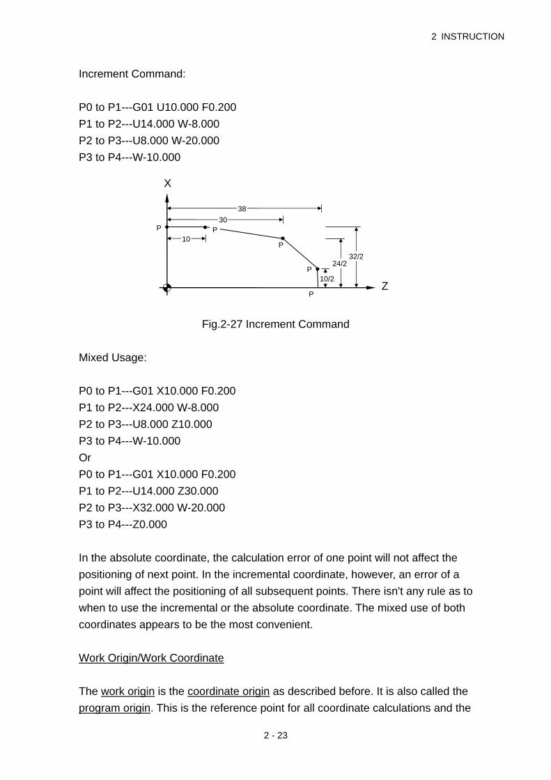
Increment Command:
P0 to P1---G01 U10.000 F0.200
P1 to P2---U14.000 W-8.000
P2 to P3---U8.000 W-20.000
P3 to P4---W-10.000
Fig.2-27 Increment Command
Mixed Usage:
P0 to P1---G01 X10.000 F0.200
P1 to P2---X24.000 W-8.000
P2 to P3---U8.000 Z10.000
P3 to P4---W-10.000
Or
P0 to P1---G01 X10.000 F0.200
P1 to P2---U14.000 Z30.000
P2 to P3---X32.000 W-20.000
P3 to P4---Z0.000
In the absolute coordinate, the calculation error of one point will not affect the
positioning of next point. In the incremental coordinate, however, an error of a
point will affect the positioning of all subsequent points. There isn't any rule as to
when to use the incremental or the absolute coordinate. The mixed use of both
coordinates appears to be the most convenient.
Work Origin/Work Coordinate
The work origin is the coordinate origin as described before. It is also called the
program origin. This is the reference point for all coordinate calculations and the
10
30 38
P
P
P
P
10/2
24/232/2
Z
X
P

HUST CNC H4D-T MANUAL
2 - 24
coordinate so obtained is called work coordinate. The reason to call it as work
origin is to differentiate it from the machine origin to be discussed in the next
section.
The work origin can be anywhere inside the machine working range. The user
should determine the location of this point before making any coordinate
calculations. Once the origin is selected, store the coordinate of this point with
respect to the machine origin in MCM parameter #1 (see Chap 4). The best
selection is the one that will make the coordinate calculation simple and easy.
X-axis of Work Origin in Lathe (X=0) should be at the centerline of Spindle.
There are three options for Z-axis of work origin:
1. The left end of Z-axis of work origin for its origin.
2. The right end of Z-axis of work origin for its origin.
3. The frontal claw or chuck for Z-axis origin in work origin.
Fig.2-28 Work origin Options (1, 2, 3)
It is an equal shape of a complete workpiece to spindle spin in Lathe CNC. Then,
it can be made at the other end. Therefore, it only takes half of the workpiece to
make in the program like the figure 2-28 below.
Fig.2-29 Workpiece Cut Diagram
Machine Origin
The machine origin is the HOME location for the cutting tool. This is the
reference point for the coordinate determination of the work origin and the tool
Z
Z 21 3

2 INSTRUCTION
2 - 25
offset compensation. The coordinate obtained using the machine origin as
calculation base is called the machine coordinate.
The exact location of the machine origin is determined by the location of the
home limit switch on each axis. When user executes X and Z Home on a Lathe
CNC controller, the cutting tool will move to the machine origin. The exact
distances between the machine origin and the work origin must be accurately
measured using a fine instrument, such as a linear scale. Otherwise, the
completed part will be in an error.
When the electric power is interrupted for any reasons, execute HOME on each
axis before resuming any cutting.
Fig.2-30 Machine Origin Diagram
2.2.1.5 Control Range
The minimum/maximum programmable range for Lathe CNC controller is as
follows. Please note that the control range may be limited by the working range
of user's machine.
Metric, mm
Min. setting unit 0.001
Max. setting unit 9999.999
Min. moving unit 0.001
Max. moving unit 9999.999
Max. setting 9999.999
X
Z Machin originZ HOME
Work originX HOME
+Z
HUST CNC H4D-T MANUAL
2 - 26
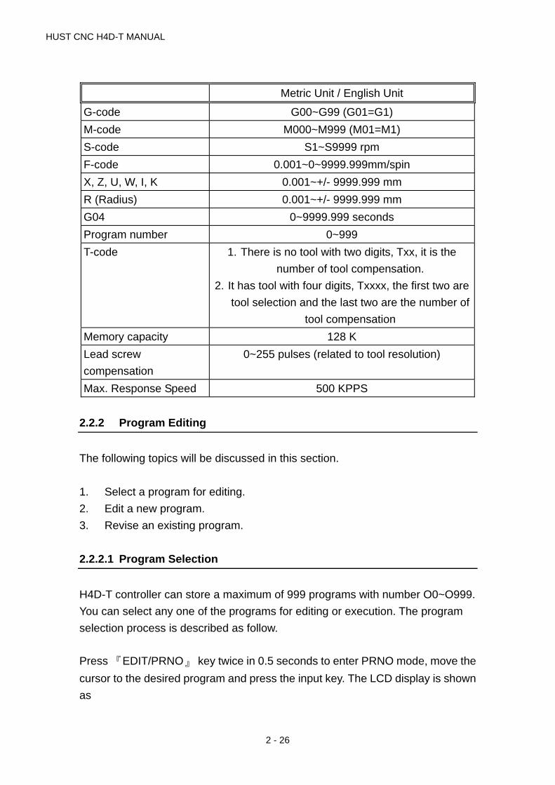
Metric Unit / English Unit
G-code G00~G99 (G01=G1)
M-code M000~M999 (M01=M1)
S-code S1~S9999 rpm
F-code 0.001~0~9999.999mm/spin
X, Z, U, W, I, K 0.001~+/- 9999.999 mm
R (Radius) 0.001~+/- 9999.999 mm
G04 0~9999.999 seconds
Program number 0~999
T-code 1. There is no tool with two digits, Txx, it is the
number of tool compensation.
2. It has tool with four digits, Txxxx, the first two are
tool selection and the last two are the number of
tool compensation
Memory capacity 128 K
Lead screw
compensation
0~255 pulses (related to tool resolution)
Max. Response Speed 500 KPPS
2.2.2 Program Editing
The following topics will be discussed in this section.
1. Select a program for editing.
2. Edit a new program.
3. Revise an existing program.
2.2.2.1 Program Selection
H4D-T controller can store a maximum of 999 programs with number O0~O999.
You can select any one of the programs for editing or execution. The program
selection process is described as follow.
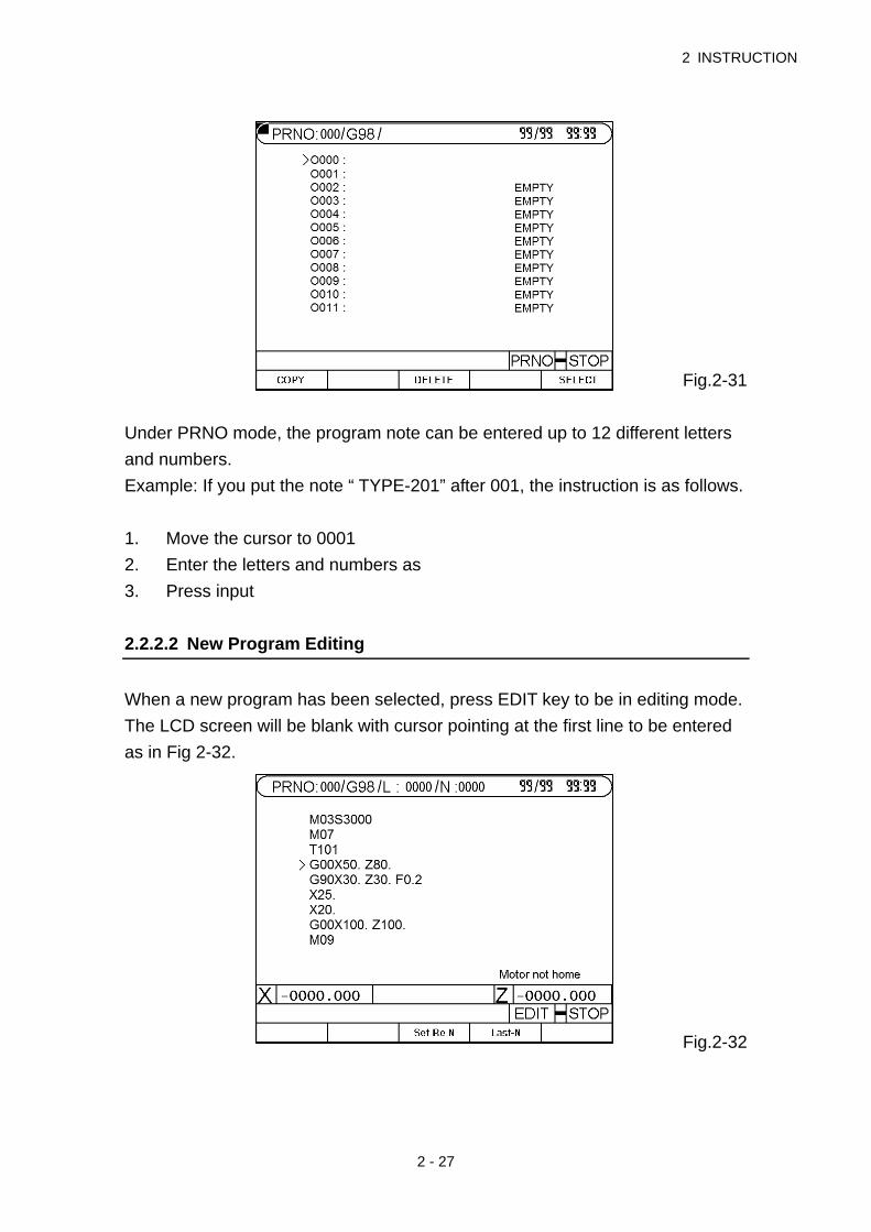
Press 『EDIT/PRNO』 key twice in 0.5 seconds to enter PRNO mode, move the
cursor to the desired program and press the input key. The LCD display is shown
as
2 INSTRUCTION
2 - 27
Fig.2-31
Under PRNO mode, the program note can be entered up to 12 different letters
and numbers.
Example: If you put the note “ TYPE-201” after 001, the instruction is as follows.
1. Move the cursor to 0001
2. Enter the letters and numbers as
3. Press input
2.2.2.2 New Program Editing
When a new program has been selected, press EDIT key to be in editing mode.
The LCD screen will be blank with cursor pointing at the first line to be entered
as in Fig 2-32.
Fig.2-32
HUST CNC H4D-T MANUAL
2 - 28
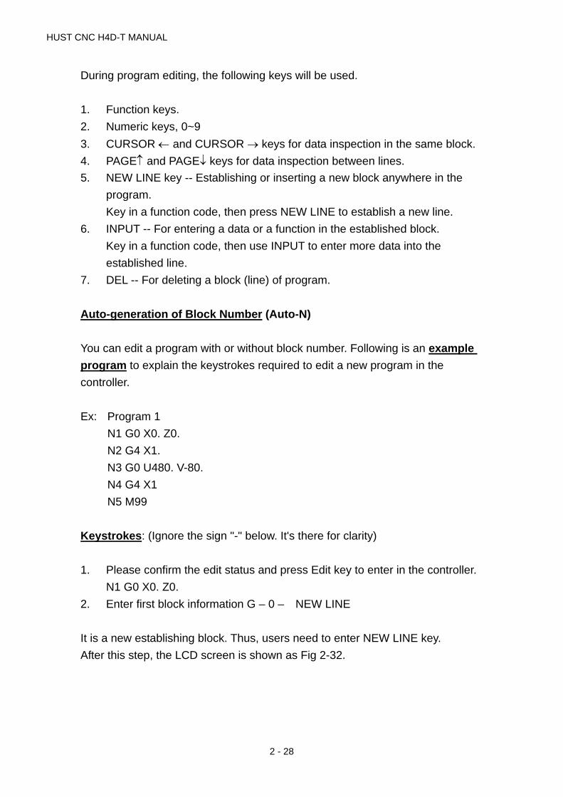
During program editing, the following keys will be used.
1. Function keys.
2. Numeric keys, 0~9
3. CURSOR and CURSOR keys for data inspection in the same block.
4. PAGE and PAGE keys for data inspection between lines.
5. NEW LINE key -- Establishing or inserting a new block anywhere in the
program.
Key in a function code, then press NEW LINE to establish a new line.
6. INPUT -- For entering a data or a function in the established block.
Key in a function code, then use INPUT to enter more data into the
established line.
7. DEL -- For deleting a block (line) of program.
Auto-generation of Block Number (Auto-N)
You can edit a program with or without block number. Following is an example
program to explain the keystrokes required to edit a new program in the
controller.
Ex: Program 1
N1 G0 X0. Z0.
N2 G4 X1.
N3 G0 U480. V-80.
N4 G4 X1
N5 M99
Keystrokes: (Ignore the sign "-" below. It's there for clarity)
1. Please confirm the edit status and press Edit key to enter in the controller.
N1 G0 X0. Z0.
2. Enter first block information G – 0 – NEW LINE
It is a new establishing block. Thus, users need to enter NEW LINE key.
After this step, the LCD screen is shown as Fig 2-32.

2 INSTRUCTION
2 - 29
Fig.2-33
And enter:
X 0 ‧ INPUT
Z 0 ‧ INPUT
Key-strokes for the remaining blocks are as follows.
1. N2 G4 X1.
(A) G - 4 - NEW LINE
(B) X - 1 - - INPUT
2. N3 G0 U480. W-480.
(A) G - 0 - NEW LINE
(B) U - 4 - 8 - 0 - - INPUT
W- "" 4 - 8 - 0 - - INPUT
(The negative sign "-" here can be input anywhere before pressing INPUT
key)
3. N4 G4 X1.
(A) G- 4 - NEW LINE
(B) X - 1 - - INPUT
4. N5 M99
(A) M - 99 - NEW LINE
During program editing, you can use CURSOR , CURSOR key to check the
input data within the block. Use PAGE, PAGE to move up and down the block
(line). When you finish editing the entire program, press RESET key to exit.

HUST CNC H4D-T MANUAL
2 - 30
2.2.2.3 Program Revision
Let's use Program O001 of previous section as our example for program
revision.
Revise or Add a Function
To revise or add a function, simply key in the function code and the correct
number, then press INPUT key.
Ex: Revise N3 U480. W-480.
To N3 U480. W-480. F0.2
1. Make sure the system in EDIT mode.
2. Use PAGE, PAGE key to move cursor to N3 block.
3. Add a function of F0.2. by entering data below and LCD will display as in
Fig 2-34
F- 0 - ‧- 2 - INPUT
4. Revise U480. to U360. by keying in
U - 3 – 6 - 0 - - INPUT
Delete a Function
To delete a function, simply key in the function to be deleted without number,
then press INPUT key.

2 INSTRUCTION
2 - 31
Ex: Revise N30 U480. W-480. F0.2
To N30 U480. W-480.
1. Make sure the system in EDIT mode.
2. Use PAGE, PAGE key to move cursor to N3 block.
3. Key "F" without numbers and press INPUT key, LCD displays as Fig 2-35.
Fig.2-35
Insert a Program Block
To insert a program block, key in the block number (or any function) and use
NEW LINE key to establish the block. Then use INPUT key to input the rest of
data for the block.
Ex: Insert N31 U20. W-20.
between N3 G0 U480. W-480. and
N4 G4 X1.
1. Make sure the system in EDIT mode.
2. Use PAGE, PAGE key to move cursor to N30 block.
3. Enter
N 3 1 new line
U 2 0 . input
W– 2 0 . input
The LCD display is shown as fig.2-36

HUST CNC H4D-T MANUAL
2 - 32
Fig 2-36
Delete a Program Block
To delete a block, use PAGE, PAGE key to move cursor to the block that you
want to delete and press DEL key. For example: Delete N31 U480 W-480. from
last example.
1. Make sure the system in EDIT mode.
2. Use PAGE, PAGE key to move cursor to N31 block.
3. Press DEL key and the LCD display is as shown in Fig 2-37 (Block N4)
Fig.2-37
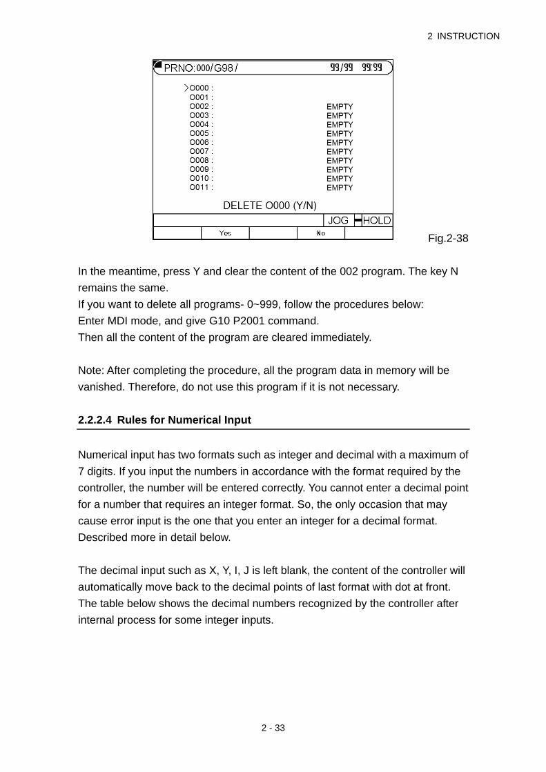
Delete a Program
Move the cursor to the program that you want to delete it in PRNO mode and
press DEL. The LCD display is shown as fig.2-38
2 INSTRUCTION
2 - 33
Fig.2-38
In the meantime, press Y and clear the content of the 002 program. The key N
remains the same.
If you want to delete all programs- 0~999, follow the procedures below:
Enter MDI mode, and give G10 P2001 command.
Then all the content of the program are cleared immediately.
Note: After completing the procedure, all the program data in memory will be
vanished. Therefore, do not use this program if it is not necessary.
2.2.2.4 Rules for Numerical Input
Numerical input has two formats such as integer and decimal with a maximum of
7 digits. If you input the numbers in accordance with the format required by the
controller, the number will be entered correctly. You cannot enter a decimal point
for a number that requires an integer format. So, the only occasion that may
cause error input is the one that you enter an integer for a decimal format.
Described more in detail below.
The decimal input such as X, Y, I, J is left blank, the content of the controller will
automatically move back to the decimal points of last format with dot at front.
The table below shows the decimal numbers recognized by the controller after
internal process for some integer inputs.

HUST CNC H4D-T MANUAL
2 - 34
Input 4/3 Format
X2 X0.002 mm
Z35 Z0.035mm
U2500 U2.500 mm
W125. W125.000mm
F300 F0.3 mm/min
The numerical formats for the function codes used in Lathe system are listed
below. To avoid any potential error, please use the specified format as follow
when key in data. The number "0" after decimal point can be omitted.
G, M, N, S-code: Variables Integer input
X, Y, Z, U, V, W, I, J-code Decimal input
F-code Integer input
Note: TO avoid the confusion, apart from integer inputs such G, M, N, S, the rest
of the inputs should be entered by decimal points. The number "0" after decimal
point can be omitted.
2.2.2.5 Notes on Program Edit
Program Block Number
1. Block number N can be omitted, but it’s better to have it for the convenience
of program inspection later.
2. Block number N is recognized by the editing order not by the block
sequence or its value. The numbers by the letter N are merely symbols. For
instance, inserting block N35 in Block N30. It will become the following
result.
Program 1
N10 G0 X0 Y0 first block
N20 G4 X1 second block
N30 U480 V-480 third block
N35 U20 V-20 fourth block
N40 G4 X1 fifth block
N50 M99 sixth block

2 INSTRUCTION
2 - 35
If block N35 is changed to block N350, the arrangement of program
execution remains the same.
3. Block number is recognized by the number of characters, not by its value.
Therefore, N10, N010, N0010 are three different block number.
Program Block
1. Do not use two G-codes in the same block. If more than one G-code exists
in a block, only the last one is effective.
2. Do not repeat any position code in the same block. The position codes are
X, Y, Z, U, V, I W, J and R.
3. If you specify absolute coordinate and incremental coordinate for the same
axis in a block, only the incremental coordinate will be executed.
Example: G1 X100. U50. -- U50 will be executed.
4. Do not exceed 80 bytes of data input for a single block. Otherwise, the CNC
controller will show an error message Err-08 at the bottom of the screen.

HUST CNC H4D-T MANUAL
2 - 36

3 G/M Codes
3 - 1
3 G/M Codes
3.1 Command codes
The previous chapters have introduced the format of part programs. This chapter
will describe the command codes of the H4D-T series and provide simple
examples for each command to explain its applications.
The definition of G-codes in the H4D-T series is similar to other controllers. They
are classified into two groups: (Table 3-1)
1. One-shot G-codes
A One-shot G-code (has no * mark in the table) is valid only in the defined
program block.
Ex: N10 G0 X30.000 Z40.000
N20 G4 X2.000 ... G4 is a one-shot G-code and is valid
only in this block.
N30 G1 X20.000 Z50.000 ... G04 no longer valid in this block.
2. Modal G-codes
A Modal G-code (has a * mark in the table) is valid until it is replaced by another
G-code of the same group.
Wherein G00, G01, G02, G03 Same group.
G40, G41, G42 Same group.
G96, G97 Same group.
G98, G99 Same group.
Ex: N10 G0 X30.000 Z5.000 ...G0 is defined.
N20 X50.000 Z10.000 ...No G-code defined, G0 remains valid.
N30 G1 X30.000 F0.2 ...G1 replaces G0 and becomes valid.
HUST CNC H4D-T Manual
3 - 2
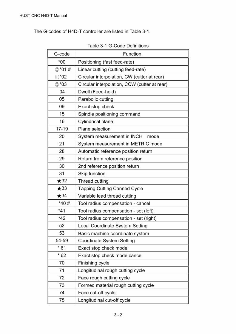
The G-codes of H4D-T controller are listed in Table 3-1.
Table 3-1 G-Code Definitions
G-code Function
*00 Positioning (fast feed-rate)
◎*01 # Linear cutting (cutting feed-rate)
◎*02 Circular interpolation, CW (cutter at rear)
◎*03 Circular interpolation, CCW (cutter at rear)
04 Dwell (Feed-hold)
05 Parabolic cutting
09 Exact stop check
15 Spindle positioning command
16 Cylindrical plane
17-19 Plane selection
20 System measurement in INCH mode
21 System measurement in METRIC mode
28 Automatic reference position return
29 Return from reference position
30 2nd reference position return
31 Skip function
★32 Thread cutting
★33 Tapping Cutting Canned Cycle
★34 Variable lead thread cutting
*40 # Tool radius compensation - cancel
*41 Tool radius compensation - set (left)
*42 Tool radius compensation - set (right)
52 Local Coordinate System Setting
53 Basic machine coordinate system
54-59 Coordinate System Setting
* 61 Exact stop check mode
* 62 Exact stop check mode cancel
70 Finishing cycle
71 Longitudinal rough cutting cycle
72 Face rough cutting cycle
73 Formed material rough cutting cycle
74 Face cut-off cycle
75 Longitudinal cut-off cycle

3 G/M Codes
3 - 3
G-code Function
★76 Compound thread cutting cycle
80 # Fixed cycle for drilling cancel
* 83 Deep hole drilling cycle (Z axis)
* 84 Tapping cycle
90 Longitudinal cutting fixed cycle
★* 92 Thread cutting fixed cycle
* 94 Face cutting fixed cycle
*96 Constant surface speed control ON
*97 # Constant surface speed control OFF
*98 Feed per minute(mm/min or in/min)
*99 # Feed per revolution(mm/revolution or in/revolution)
# -- G-codes with "#" are of power-on default setting.
* -- G-codes with "*" are modal G-codes.
★-- Function code prefixed with ★ mark needs to be carried
out in G99 mode.

HUST CNC H4D-T Manual
3 - 4
3.2 Positioning, G00
Functions and Purposes:
This command is accompanied with a coordinate name; it takes the current
position as the staring point and the coordinate indicated by the coordinate name
as the end point, which are positioned by the linear path.
Format:
G00 X(U)____ Z(W)____
X, Z : End point in absolute coordinates.
U, W : End point in incremental coordinates relative to the block
starting point.
Fig. 3-1 Fast positioning
Details: 1. Once this command is given, the G00 mode is kept effective until a G01,
G02, G03, or other single-time G command appears. Therefore if a
subsequent command is also G00, only the axis address needs to be
specified.
2. The speed of positioning is set by a machine parameter.
3. This command is capable of controlling movements in 1-6 axes
simultaneously. No position movement will take place if the command gives
no axis direction.
Example: Fig 3-2, A point moves to B point rapidly.
G0 X4.00 Z5.60 ...X and Z-axes are set with absolute commands
G0 U-6.00 W-3.05 ...X and Z-axes are set with incremental commands
Z
X W
U2
1G00
X
Z

3 G/M Codes
3 - 5
G0 X4.00 W-3.05 ...X and Z-axes are set with absolute or incremental
commands
Fig. 3-2 G00 Programming Example
Tool moves to X4.00, Z5.60 rapidly. Since both X and Z axes are repositioning,
the tool moves according to the lower feed-rate set in the parameter “Highest
Feed-rate”.Ex: Fig. 3-2 assuming that the “Highest Feed-rate” is:
X = 5000.00 mm/min, Z = 3000.00 mm/min,
Then Fz =3000.00 ...Z-axis feed-rate
Fx = 3000.00 * (3.00/3.05)
= 2950.82 (less than 5000.0, X- axis set value) ...X-axis feed-rate
The feed rate of both axes is within the MCM parameter settings. Therefore, the
tool will feed at the calculated rate on both axes.
When only a single axis (X or Z) executes fast positioning, it moves at the
respective speed set in the “Highest Feed-rate” parameter.
3.3 Linear Cutting, G01
Functions and Purposes:
This command, together with the coordinates and a feed speed command,
makes the tool to move from the current position to the end point specified by the
coordinates in a linear movement at the speed specified by address F.
Format:
G01 X(U)____ Z(W)____ F____
A
B
x
z
5.63.05
3.00
2.00

HUST CNC H4D-T Manual
3 - 6
X, Z : End point in absolute coordinates
U, W : End point in incremental coordinates relative to the start point
of the program block.
F : Cutting feed-rate (F-code can be used in combination with any
G-code)
The F-code can be used in the G00 block without affecting the fast positioning
movement.
Details:
1. G01 (or G1) is used for linear cutting work. It can control the X, Z-axes
simultaneously. The cutting speed is determined by the F-code. The smallest
setting value of the F-code is 0.02 mm/min or 0.2 in/min.
2. Once this command is given, the G01 mode is kept effective until a G01,
G02, G03, or other single-block G command appears. Therefore if a
subsequent command is also G01 and the feed speed is not changed, only
the coordinate value needs to be specified.
3. The starting point is the coordinate of the tool when the command is given. The
feed-rate defined after an F-code (Modal code) remains valid until it is replaced
by a new feed-rate.
The formula to calculate X, Z cutting feed-rate:
(U and W are actual incremental values.)
X feed-rate, FxU
U WF
2 2 (1)
Z feed-rate, FzW
U WF
2 2 (2)
Example: Start point is X=2.0 (diameter), Z=4.60.
G01 X4.00 Z2.01 F0.300 ...Absolute command
G01 U2.00 W-2.59 F0.300 ...Incremental command

3 G/M Codes
3 - 7
Fig. 3-3 G01 Programming Example
3.4 G02, G03 Circular Interpolation
Functions and Purposes:
This command makes the tool move along an arc.
Format:
G02 X(U)____ Z(W)____ I____ K____ F____
Fig 3-4 G02 Arc cutting
G03 X(U)____ Z(W)____ I____ K____ F____
Fig 3-5 G03 Arc Cutting
G02 X(U)____ Z(W)____ R____ F____
2.0
4.6 1.00Z
X
B
A
Z
X
X/2
ES
End
Start
ZK
I
Z
X
X/2
ESEnd
Start
ZK
I

HUST CNC H4D-T Manual
3 - 8
Fig. 3-6 Defined by Radius “R”
Details:
1. The arc-cutting program contains four command groups, as showed in the
list below. The combination of these commands determine the arc path of
the tool in a single block.
Table 3-2
Command Description
1 Arc feed direction G02
G03
Clockwise
Counter clockwise
2 End point
Absolute
command
Incremental
command
X, Z
U, W
End point in absolute
coordinates
Increment from arc start
point to end point
3
Difference from arc
start point to center
Arc radius
I, K
R
I=X-axis, K=Z-axis
Radius range
-9999.~9999.mm
4 Arc feed-rate F
Minimum setting 0.01
mm/rot.
2. The end point can be defined either by absolute or incremental coordinates.
The size of the arc can be defined either by the coordinate difference or
radius. The arc cutting direction (CW or CCW) is relative to the center of
the arc. Note that the CW or CCW direction is determined when the tool is
at the top (rear) holder. The direction is reversed when the tool is at the
bottom (front) holder.
Z
X
X/2
E
SEnd
Start
Z
R
3 G/M Codes
3 - 9
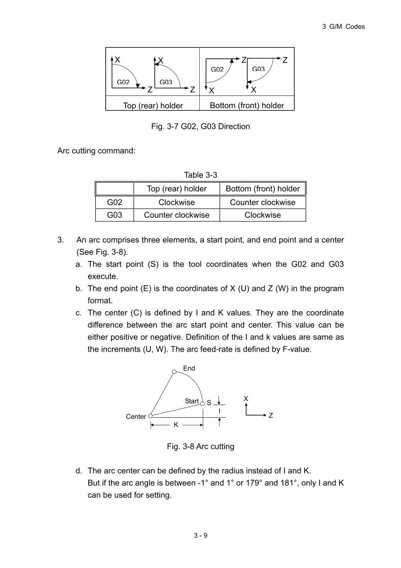
Fig. 3-7 G02, G03 Direction
Arc cutting command:
Table 3-3
Top (rear) holder Bottom (front) holder
G02 Clockwise Counter clockwise
G03 Counter clockwise Clockwise
3. An arc comprises three elements, a start point, and end point and a center
(See Fig. 3-8).
a. The start point (S) is the tool coordinates when the G02 and G03
execute.
b. The end point (E) is the coordinates of X (U) and Z (W) in the program
format.
c. The center (C) is defined by I and K values. They are the coordinate
difference between the arc start point and center. This value can be
either positive or negative. Definition of the I and k values are same as
the increments (U, W). The arc feed-rate is defined by F-value.
Fig. 3-8 Arc cutting
d. The arc center can be defined by the radius instead of I and K.
But if the arc angle is between -1° and 1° or 179° and 181°, only I and K
can be used for setting.
Start
End
Center
S
K
I
X
Z
G02
X
Z G03
X
Z
G02
X
ZG03
X
Z
Top (rear) holder Bottom (front) holder

HUST CNC H4D-T Manual
3 - 10
Example:
1. The following four commands are different in settings but execute the same
arc cutting work.
a. G02 X5.000 Z3.000 I2.500 F0.3
b. G02 U2.000 W-2.000 I2.500 F0.3
c. G02 X5.000 Z3.000 R2.500 F0.3
d. G02 U2.000 W-2.000 R2.500 F0.3
Fig. 3-9 G02 Programming Example
2. There are two different arc types available for arc cutting (Fig. 3-10):
a. Use “+R" if arc angle < 180°.
b. Use “-R" if arc angle > 180°. R is within the range from -4000.mm to +4000.mm.
Ex: In Fig. 3-10, an arc is cut with an angle <180°(+R):
G02 Z60.000 X20.000 R50.000 F0.300
Fig. 3-10 Arc cutting
Please note the following when executing an arc cutting:
1. The F-value of the cutting speed is given in a G02/G03 command,
indicating the speed along the tangent to the arc; this tangent speed is
limited by the arc radius and the given speed limit.
S
Start
EndE
RX
Z
3.0
X
E
S
End
Start
Z
R = 2.5
5.0
5/23/2
2/2

3 G/M Codes
3 - 11
2. When the calculated tangential cutting speed of the arc is greater than the F
value of the program, the F-value is used as the tangential cutting speed.
Otherwise, the calculated value prevails.
3. The maximum tangential cutting speed is estimated with the following
formula:
100085 RFc mm/min
Where R= Arc radius in mm.
3.5 Dwell , G04
Functions and Purposes:
This function’s purpose is to temporarily hold the machine movement via the
program command, realizing a waiting status, therefore delaying the start of the
subsequent block.
Format:
G04 X(P)____
X: Dwell Time. Unit: second. (The X here stands for time instead of
position, is dependent on the setting of “decimal enable” parameter. Ex.:
G04 X2, when “decimal enable” is disabled, the dwell time is 2s; if
“decimal enable” is enabled, the dwell time is 0.002s – i.e. 2ms.)
P: Dwell Time. Unit: millisecond. (Not dependent on the setting of “decimal
enable” parameter.)
Details:
To meet machining requirements, the axial movement may need to be held
during the execution of a program block, which completes before the command
for the next block is executed. This command can be used for this purpose. The
G04 function is used for this purpose.
The minimum dwell time is 0.001 sec, the maximum is 8000.0 seconds.

HUST CNC H4D-T Manual
3 - 12
Ex: N1 G1 X10.000 Z10.000 F0.1
N2 G4 X2.000 .....hold for 2 seconds
N3 G00 X0.000 Z0.000
3.6 Parabolic cutting, G05
Function and purpose:
The function will make the tool along a parabolic mobile.
Form :
G05 X(U)___ Z(W)___ P___ I___ K___ J___ F___
X,Z : The parabola the end of the absolute coordinates value.
U,W : The parabola the end of the incremental value relative to the
starting point of the single block.
Note:When parabolic End X coordinate and the parabola starting point X
coordinate equal, display will showing “ERROR 05 .X”.
When parabolic End Z coordinate and the parabola starting point Z
coordinate equal, display will showing “ERROR 05 .Z”.
P : Parabolic program X2=4PZ P value, Range(1~9999999), Unit:0.001mm,
Degree of opening of said parabolic shape.(When P≤0, system will showing
“ERROR 05.P” to the display)
I : The parabola X-axis interpolation step value, Range(0.001~9999.999),
Step away from the smaller, the precision will more higher.(When the X-axis
step distance value I≤0 , system will showing “ERROR 05 .I” to the display)
K : K=0 Counterclockwise parabolic parabola trajectory from the beginning to
the end.
K=1 Parabolic trajectory from the beginning to the end clockwise
parabolic.

3 G/M Codes
3 - 13
The system default counterclockwise parabolic when K not fill.
J : J=0 The parabola command in prevenient processing can do tool
compensation, but the surface finish is not high.
J=1 The parabola command in at the point of interruption, can not do the
tool compensation but high surface finish.
The system default J=0 when J not fill.
F : Speed feed-rate (Can be used in conjunction with any G-code).
Fig 3-11 K explanation
Rear turret coordinates Front turret coordinates

HUST CNC H4D-T Manual
3 - 14
Program example:
When Parabolic command P=5mm, Its symmetry axis parallel to the Z-axis
machining dimensions of the parts shown in the Figure, the finishing program
may be prepared as follows:
Fig 3-12
M03 S800
G00 X10. Z10.
G00 X0.
G01 Z0. F120
M08
X30.
G05 X60. Z-40. P5000 K0 I1.
G01 X90. Z-60.
X110. Z-85.
X120.
M09
G00 Z10.
M30
3 G/M Codes
3 - 15
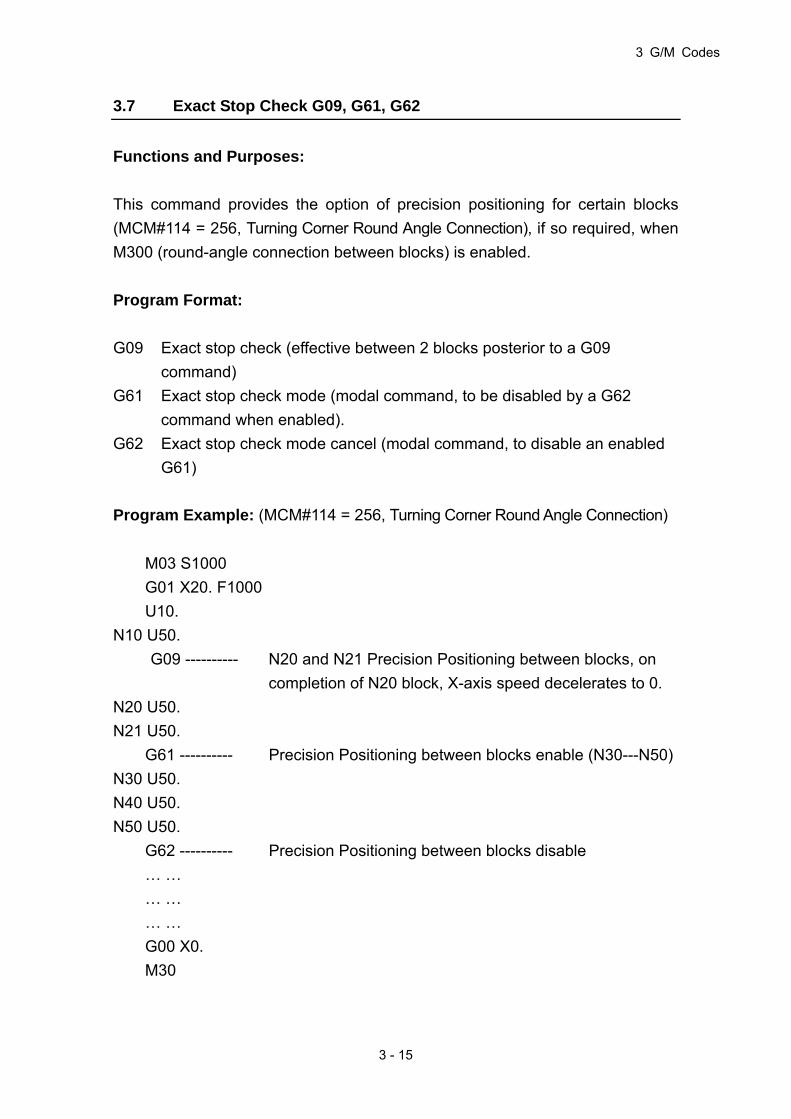
3.7 Exact Stop Check G09, G61, G62
Functions and Purposes:
This command provides the option of precision positioning for certain blocks
(MCM#114 = 256, Turning Corner Round Angle Connection), if so required, when
M300 (round-angle connection between blocks) is enabled.
Program Format:
G09 Exact stop check (effective between 2 blocks posterior to a G09
command)
G61 Exact stop check mode (modal command, to be disabled by a G62
command when enabled).
G62 Exact stop check mode cancel (modal command, to disable an enabled
G61)
Program Example: (MCM#114 = 256, Turning Corner Round Angle Connection)
M03 S1000
G01 X20. F1000
U10.
N10 U50.
G09 ---------- N20 and N21 Precision Positioning between blocks, on
completion of N20 block, X-axis speed decelerates to 0.
N20 U50.
N21 U50.
G61 ---------- Precision Positioning between blocks enable (N30---N50)
N30 U50.
N40 U50.
N50 U50.
G62 ---------- Precision Positioning between blocks disable
… …
… …
… …
G00 X0.
M30
HUST CNC H4D-T Manual
3 - 16
3.8 Spindle Positioning Command, G15
Functions and Purposes:
This command sets the Spindle to a Position.
Program Format:
G15 R_____P_____
Parameters:
R: Stands for the Target Angle of Spindle Positioning
P: Stands for rpm of Spindle Positioning
Details:
R Parameter Format: With decimal point or omit decimal point and add 2 zeros
at the end.
Program Example:
EX.: For spindle to be positioned at the angle of 175 degrees, any of the
following commands may be given:
Method 1: G15 R175. 00
Method 2: G15 R175.
Method 3: G15 R17500
3.9 Cylindrical Plane, G16
Functions and Purposes:
Using the angular movement of an angle command, convert it internally into a
linear distance of the axis on the outer surface, for performing a linear
interpolation or arc interpolation with another axis. After the interpolation, this
distance is again converted into the movement of the rotating axis.
Program Format:

3 G/M Codes
3 - 17
1. Directly specify a cylinder interpolation axis and cylinder radius.
G16 Yxxxx.xxx: Set Y-axis as the cylinder interpolation axis, xxxx.xxx as
value of cylinder radius.
G16 Axxxx.xxx: Set A-axis as the cylinder interpolation axis, xxxx.xxx as
value of cylinder radius.
G16 Bxxxx.xxx: Set B-axis as the cylinder interpolation axis, xxxx.xxx as
value of cylinder radius.
G16 Cxxxx.xxx: Set C-axis as the cylinder interpolation axis, xxxx.xxx as
value of cylinder radius.
2. Only set the value of cylinder radius; the cylinder interpolation axis to be
determined by the currently used spindle. (I.e., the axial direction for
switching from the spindle mode to the servo axis mode.)
G16 Hxxxx.xxx : Set xxxx.xxx as the value of cylinder radius.
When set with this method, the cylinder interpolation axis to be determined
by the currently using spindle, and the current spindle must be converted
into servo axis for performing cylinder interpolation.
Ex: First Spindle (C-axis) to be switched over to servo spindle mode for
performing cylinder interpolation.
……
N01 M50 … First spindle switched into servo mode
N10 G01 C0. … Positioning
N20 G18 Z0 C0 … Select Z-C plane
N30 G16 H20. … Cylinder interpolation enable, C-axis is
cylinder interpolation axis; cylinder radius
20mm.
N40 G42 Z10.F1.0 … Interpolate Tool Tip Radius Offset
N50 G01 Z10.C30. … Linear Interpolation
N60 G03 Z40.C60.R30. … Arc Interpolation
N70 G01 Z60.C90. … Linear Interpolation
N80 G40 Z90. … Tool Tip Radius Offset disable
N90 G16 C0 … Cylinder Interpolation disable
N100 M51 … Switch into spindle mode
……
Note
HUST CNC H4D-T Manual
3 - 18
1. If xxxx.xxx 0, cylinder interpolation function is enabled.
If xxxx.xxx=0, cylinder interpolation function is disabled.
2. Specifies G-code selection plane; for this plane, the rotation axis is the
specified linear axis.
3. EX.: If the rotation axis is parallel to an X-axis, G17 must specify an X-Y
plane which is defined by the rotation axis and Y-axis, or a plane that is
parallel to the Y-axis.
4. Feed speed specified in cylinder interpolation is the speed upon the
spread surface of the cylinder.
5. In cylinder interpolation mode, arc radius in G02/G03 can only be
specified with R parameter instead of I, J, or K.
EX:Cylinder interpolation mode (Cylinder interpolation in Z-axis and
C-axis)
G18 Z____ C____
G02(03)Z____ C____ R____
6. Tool-tip compensation is possible in cylinder interpolation mode. In
order to carry out tool compensation in cylinder interpolation, any other
in-progress tool compensation must be disabled before entering
cylinder interpolation, then start and end tool compensation in cylinder
interpolation mode.
7. If cylinder interpolation is started when a tool-tip compensation is in
application, an arc interpolation cannot be accomplished correctly in
cylinder interpolation.
8. In cylinder interpolation, the movement of a rotating axis activated by an
angular command is transformed as a distance in a linear axis for
carrying out linear interpolation or arc interpolation with another axis.
After interpolation, this distance is transformed back to an angle. For
this transformation, input of displacement is the minimum incremental
unit. When the cylinder has a small radius, the actual displacement is
not equal to the specified displacement; however this error is not
accumulative.
9. Cylinder interpolation function ends when a reset is activated.
10. A cylinder interpolation axis must be set as a rotation axis, and only one
rotation axis shall be set.

3 G/M Codes
3 - 19
Program Example:
Fig. 3-13 Cylinder Interpolation

HUST CNC H4D-T Manual
3 - 20
3.10 Plane setup, G17-G19
Functions and Purposes:
This command is for selecting a control plan or the plane where an arc is
located.
Program Format:
1. If no axis direction is specified after a G17, G18, or G19 command, the arc
plane is the default plane as shown below:
Fig. 3-14 Arc Plane
Table 3-4
Command Horizontal Axis Vertical Axis
G17 (IJ Plane selection) X Y
G18 (KI Plane selection) Z X
G19 (JK Plane selection) Y Z
3 G/M Codes
3 - 21
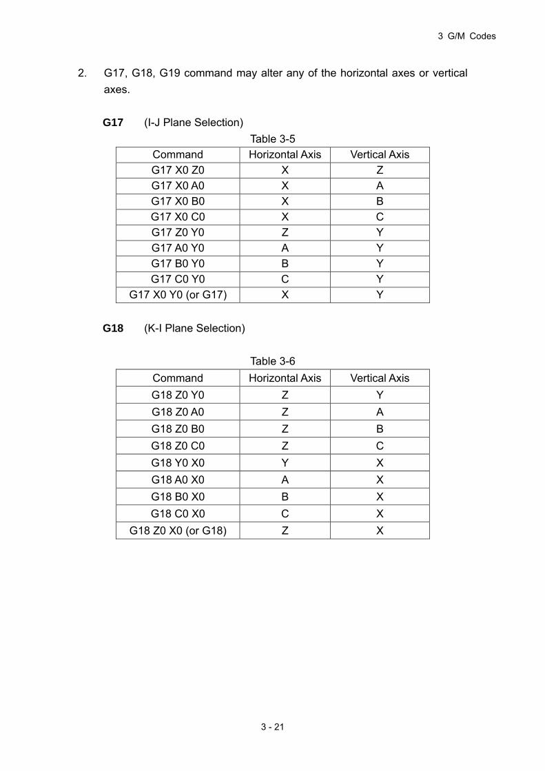
2. G17, G18, G19 command may alter any of the horizontal axes or vertical
axes.
G17 (I-J Plane Selection)
Table 3-5
Command Horizontal Axis Vertical Axis
G17 X0 Z0 X Z
G17 X0 A0 X A
G17 X0 B0 X B
G17 X0 C0 X C
G17 Z0 Y0 Z Y
G17 A0 Y0 A Y
G17 B0 Y0 B Y
G17 C0 Y0 C Y
G17 X0 Y0 (or G17) X Y
G18 (K-I Plane Selection)
Table 3-6
Command Horizontal Axis Vertical Axis
G18 Z0 Y0 Z Y
G18 Z0 A0 Z A
G18 Z0 B0 Z B
G18 Z0 C0 Z C
G18 Y0 X0 Y X
G18 A0 X0 A X
G18 B0 X0 B X
G18 C0 X0 C X
G18 Z0 X0 (or G18) Z X

HUST CNC H4D-T Manual
3 - 22
G19 (J-K Plane Selection)
Table 3-7
Command Horizontal Axis Vertical Axis
G19 Y0 X0 Y X
G19 Y0 A0 Y A
G19 Y0 B0 Y B
G19 Y0 C0 Y C
G19 X0 Z0 X Z
G19 A0 Z0 A Z
G19 B0 Z0 B Z
G19 C0 Z0 C Z
G19 Y0 Z0 (or G19) Y Z
Note:
1. In a plane layout command, there is no fixed sequence for the horizontal
and vertical axes. EX.: G17 X0 Z0 = G17 Z0 X0。
2. In G17, always use the IJ value to indicate the radial increment from the
start point of an arc.
In G18, always use the KI value to indicate the radial increment from the
start point of an arc.
In G19, always use the JK value to indicate the radial increment from the
start point of an arc.
EX.:
G17 X0 Z0 (Select X/Z plane)
G02 X10. Z10. J10. (J stands for the radial increment of the arc from
the starting point of the vertical axis (Z-axis) (to
the center of the arc).

3 G/M Codes
3 - 23
3.11 Automatic Reference Position Return, G28
Functions and Purposes:
Via a G28 command, the specified axis is returned to the first reference point at
the high feed-speed of the respective axis.
Format:
G28
or G28 X(U)_____ Z(W)_____
or G28 X(U)_____
or G28 Z(W)_____
Example:
Note that prior to executing the G28 command, the tool compensation command
must be canceled.
Ex:
G00 X1. Z1 ... (From start-point to the intermediate point)
T100 ... Tool compensation is canceled (it cannot co-exist
with G28 in the same block.
G28 ... Tool returns to the 1st reference point on the X /
Z-axis.
HUST CNC H4D-T Manual
3 - 24
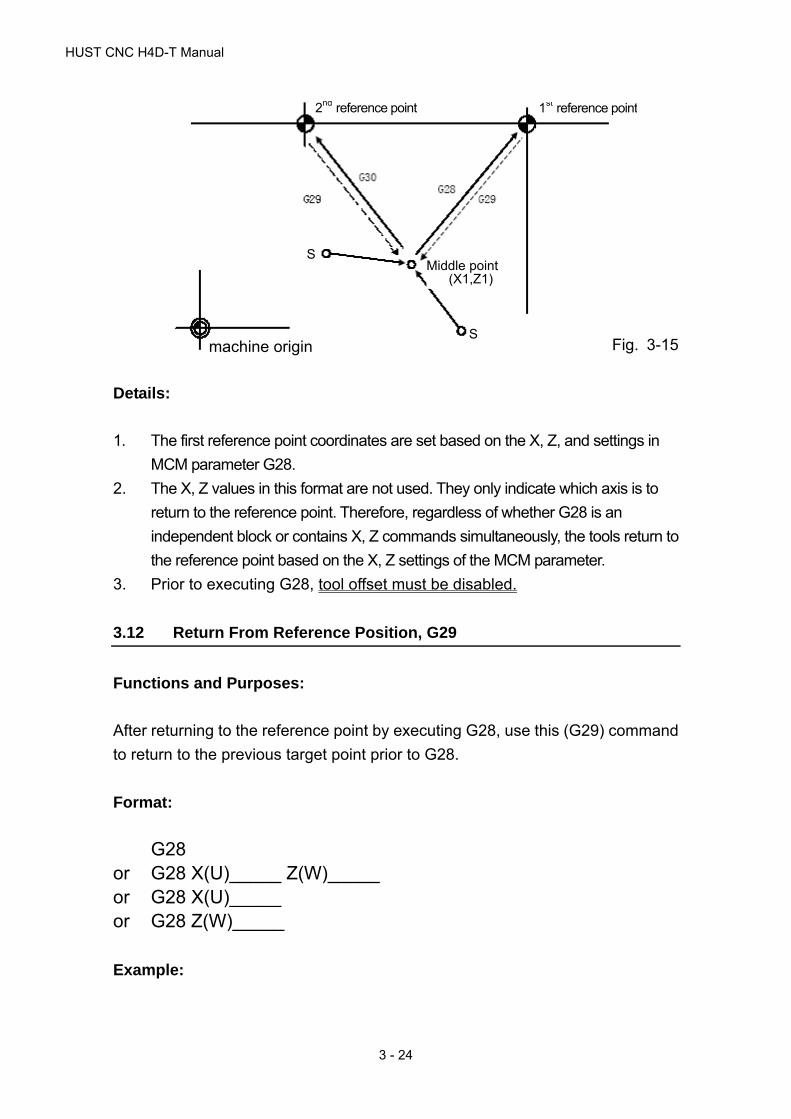
2nd reference point 1st reference point
machine origin
S Middle point
(X1,Z1)
S
Fig. 3-15
Details:
1. The first reference point coordinates are set based on the X, Z, and settings in
MCM parameter G28.
2. The X, Z values in this format are not used. They only indicate which axis is to
return to the reference point. Therefore, regardless of whether G28 is an
independent block or contains X, Z commands simultaneously, the tools return to
the reference point based on the X, Z settings of the MCM parameter.
3. Prior to executing G28, tool offset must be disabled.
3.12 Return From Reference Position, G29
Functions and Purposes:
After returning to the reference point by executing G28, use this (G29) command
to return to the previous target point prior to G28.
Format:
G28 or G28 X(U)_____ Z(W)_____ or G28 X(U)_____ or G28 Z(W)_____
Example:
3 G/M Codes
3 - 25
EX: N1 G00 X1. Z1. ...(From start-point to intermediate point)
N2 T00 ...Offset disabled (shall not situate at the same block
with G28)
N3 G28 ...X-Axis/Z-Axis returns to first reference point
N4 G29 ...Program returns from first reference point to (X1, Z1).
(See Fig. 3-15)
As the example above, the N3 block may have the following combinations:
N4 G29 X _____ Z _____ ...Return to (X1. Z1.)
N4 G29 X _____ ...Tool returns to X1.
N4 G29 Z _____ ... Tool returns to Z1.
Details:
1. The X/Z Value in the program format is insignificant; however, a value must
be given for entering into the program, it merely tells the machine to which
axis the reference point is to be returned.
2. After executing G28, use G29 command to return the tool to its previous
position before G28 is executed.
3. The G29 command cannot be used alone. A G28 or G30 must be given
prior to G29.
3.13 2nd Reference Position Return, G30
Functions and Purposes:
Via G30 command, the specified axis is returned to the second reference point
at high feed-speed of the respective axis.
Format:
G30
or G30 X(U)_____ Z(W)_____
or G30 X(U)_____
or G30 Z(W)_____
Execution of this command is the same as G28, but the reference point is set in MCM
parameter G30. (See Fig 3-15)

HUST CNC H4D-T Manual
3 - 26
3.14 Thread Cutting, G32
Functions and Purposes:
G32 command performs spindle rotation by synchronized control of tool-feed;
therefore it is capable of processing linear thread cutting, inclined thread cutting
and continuous thread cutting.
Fig. 3-16 G32 Thread cutting
Format:
G32 X(U) _____ Z(W) _____ F _____ Q _____ E _____
Fig. 3-17 Thread Cutting
(The U/2 Setting Should Not be Less Than Retraction Amount)
X, Z : End point of thread cutting in absolute coordinates
U, W : End point of thread cutting in incremental coordinates relative to
the start point.
F : Thread pitch
Q : Start-angle of thread cutting; default value: Q=0 (range of angle
is 0-359 without a decimal point)
E : Number of threads per inch; range: 1.0-100.0. This setting shall
not appear when an F setting is given.
X
Z 20 mm
S2 S1
U/2
X/2
WZ

3 G/M Codes
3 - 27
Details:
1. Both fine cut and rough cut of the thread cutting proceed along the same path.
The cutting action on the Z-axis does not start until the Grid signal is received
from the spindle. All repeated cutting actions start at the same point.
2. Due to delay of the server system, imperfections could result at both ends of
the thread (S1 and S2). To avoid this problem, the thread length specified in
the program should be slightly longer than the actual length of the processed
thread. S1 and S2 are leads. The length of S1 and S2 is estimated using the
formula below.
S1 = (S * F/1800) * (-1 - Ln A)
S2 = (S * F/1800)
S1, S2 : Imperfect thread length, mm
S : Spindle speed, rpm
F : Thread pitch, mm
A : Acceptable thread error
Relationship between A and (-1 - Ln A):
Table 3-8
A -1 - Ln A
0.005 4.298
0.010 3.605
0.015 3.200
0.020 2.912
0.025 2.689
Example :
Ex 1: Non-tapered thread cutting
Specifications: Thread pitch F= 2 mm,
cutting lead starts S1 = 3 mm,
cutting lead ends S2 = 3 mm,
Thread depth = 1.4 mm (in diameter) by 2 cuts

HUST CNC H4D-T Manual
3 - 28
Fig. 3-18 Non-tapered Thread Cutting
N10 G0 X30.0 Z50.0
N20 M03 S2000
N30 G0 U-17.000 (first cut = 1.0/2mm)
N40 G32 W-26.000 F2.00
N50 G0 U17.000
N60 W26.000
N70 G0 U-17.400 (second cut = 0.4/2mm)
N80 G32 W-26.000 F2.00
N90 G0 U17.400
N100 W26.000
N110 M05
N120 M02
Ex 2 : Tapered thread cutting
G32 X(U) _____ Z(W) _____ F _____ R _____ Q _____ E _____
X, Z : End point of thread cutting in absolute coordinates.
U, W : End point of thread cutting in incremental coordinates relative to
the start point.
F : Thread pitch.
R : Half of the difference (diameter) between the greater and
smaller ends of the tapered thread.
Q : Start-angle of thread cutting; default value: Q=0 (range of angle
is 0-359 without a decimal point)
E : Number of threads per inch; range: 1.0-100.0. This setting shall
not appear when an F setting is given.
Specifications:
Thread pitch F=2 mm
Cutting lead starts S1 = 2 mm,
X
Z 20 mm
3 3
17/2 mm

3 G/M Codes
3 - 29
Cutting lead ends S2 = 2 mm,
Thread depth = 1.4 mm (diameter) formed by two cutting
actions.
Fig 3-19 Tapered Thread Cutting
Note: Tapered thread
a. For the angle between taper plane and Z-axis less than 45°, pitch shall
be set along the Z-axis.
b. For the angle between taper plane and Z-axis more than 45°, pitch
shall be set along the X-axis.
c. For the angle between taper plane and Z-axis equal to 45°, pitch can
be set along either the X-axis or Z-axis.
N10 GO X60.0 Z100.0
N20 M03 S2000
N30 G0 X23.0 Z72.0 (First cut = 1.0/2mm)
N40 G32 X32.000 Z28.000 F2.00 R-4.5
N50 G0 X40.000
N60 Z72.000
N70 G0 X22.6 (Second cut = 0.4/2mm)
N80 G32 X31.6 Z28.0 F2.00 R-4.5
N90 G0 X40.000
N100 Z72.000
N110 M05
N120 M02
Ex 3 : Multi-stage continuous thread cutting
G00 Z0.
M03 S3000 ; Quick positioning to start point
G32 Z50.F1. ; Thread of first stage
G32 Z100.F2. ; Thread of second stage
X
Z 40 33 2
2 24
30 40
HUST CNC H4D-T Manual
3 - 30
G32 Z150.F3. ; Thread of third stage
M05
M30
If set as above, the thread cutting process will have no stop in the Z-axis during
thread cutting, therefore the cut threads are smooth and continuous.
3.15 G33 Tapping Cutting Canned Cycle
Purpose and Function:
Rigid thread cutting
Command Format:
G33 Z(W)_________ F______
G33 X(U)_________ F______
Z(W) X(U) : End-point coordinate or length of thread cutting
F : Pitch
Details: Execution process of Z/X-axis thread cutting
1. Z/X Axis feed of thread cutting
2. Switch off spindle
3. Wait until the spindle fully stops
4. Reverse the spindle (in the opposite direction of the original rotation)
5. Z/X-axis tool retracts
6. Spindle stops
Program Example: One-end thread with 1mm pitch (e.g., in Z-axis):
N10 M3 S800
N20 G33 Z100. F1.0
N30…
Note 1: Ensure the spindle rotation is in the threading direction before starting
thread cutting. Spindle will stop rotation when the thread cutting is

3 G/M Codes
3 - 31
completed. For the subsequent process, start the spindle as required.
Note 2: Since this command is a rigid thread cutting, when a spindle stop
command is enabled, the spindle decelerates for a certain period of time
before reaching the full stop, and Z-axis will still move along with spindle
rotation before spindle fully stops. Therefore for the actual process, the
end of thread cutting will be a little bit deeper than the actual
requirement.
Note 3: Other precautions are the same as that of G32 Thread Cutting.
3.16 G34 Variable Lead Thread Cutting
Functions and Purposes:
Applicable for processing variable lead threads
Command Format:
G34: X(U)___ Z(W)___ F___ K±___ Q___ E___
1) Parallel thread: G34 Z(W)__ F__ Q__ K__;
2) Tapered thread: G34 X(U)__ Z(W)__ F__ Q__ K__;
X、Z : End point of thread cutting in absolute coordinates
U、W : End point of thread cutting in incremental coordinates relative to
the start point
F : Thread Pitch
K : Start-angle of thread cutting; default value: Q=0 (range of angle
is 0-359 without a decimal point)
E : Number of threads per inch; range: 1.0-100.0. This setting shall
not appear when an F setting is given.
Fig.3-20
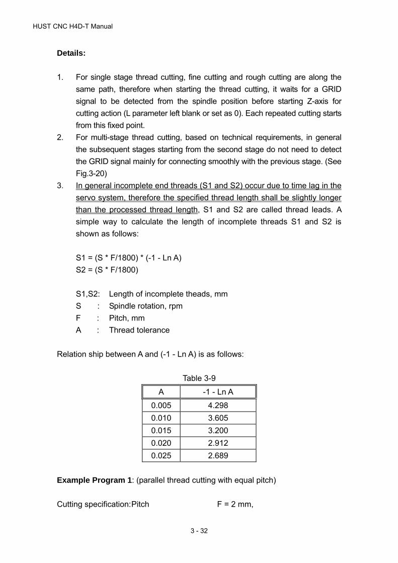
HUST CNC H4D-T Manual
3 - 32
Details:
1. For single stage thread cutting, fine cutting and rough cutting are along the
same path, therefore when starting the thread cutting, it waits for a GRID
signal to be detected from the spindle position before starting Z-axis for
cutting action (L parameter left blank or set as 0). Each repeated cutting starts
from this fixed point.
2. For multi-stage thread cutting, based on technical requirements, in general
the subsequent stages starting from the second stage do not need to detect
the GRID signal mainly for connecting smoothly with the previous stage. (See
Fig.3-20)
3. In general incomplete end threads (S1 and S2) occur due to time lag in the
servo system, therefore the specified thread length shall be slightly longer
than the processed thread length, S1 and S2 are called thread leads. A
simple way to calculate the length of incomplete threads S1 and S2 is
shown as follows:
S1 = (S * F/1800) * (-1 - Ln A)
S2 = (S * F/1800)
S1,S2: Length of incomplete theads, mm
S : Spindle rotation, rpm
F : Pitch, mm
A : Thread tolerance
Relation ship between A and (-1 - Ln A) is as follows:
Table 3-9
A -1 - Ln A
0.005 4.298
0.010 3.605
0.015 3.200
0.020 2.912
0.025 2.689
Example Program 1: (parallel thread cutting with equal pitch)
Cutting specification: Pitch F = 2 mm,

3 G/M Codes
3 - 33
Lead for start-of-cutting S1 = 3 mm,
Lead for end-of-cutting S2 = 3 mm,
Cutting depth = 1.4 mm (diameter), in 2 cutting
sessions
Fig.3-21 Parallel thread cutting with equal pitch
N10 G0 X30.0 Z50.0
N20 M03 S2000
N30 G0 U-17.000 (first cutting 1.0/2mm)
N40 G34 W-26.000 F2.00 K0.5
N50 G0 U17.000
N60 W26.000
N70 G0 U-17.400 (second cutting 0.4/2mm)
N80 G34 W-26.000 F2.00 K0.5
N90 G0 U17.400
N100 W26.000
N110 M05
N120 M02
Program Example 2: (Tapered thread cutting)
Cutting specifications: Pitch F = 2 mm,
Lead for start-of-cutting S1 = 2 mm,
Lead for end-of-cutting S2 = 2 mm,
Cutting depth = 1.4 mm (diameter), in 2 cutting
sessions
Fig.3-22 Tapered thread cutting
X
Z 20 mm
3 3
17/2 mm
X
Z 40 33 2
2 24
30 40

HUST CNC H4D-T Manual
3 - 34
Tapered threads, for angle between taper plane and Z-axis less than 45°, pitch
shall be set along Z-axis, for angle between taper plane and Z-axis more than
45°, pitch shall be set along X-axis.
N10 GO X60.0 Z100.0
N20 M03 S2000
N30 G0 X23.000 Z72.000 (First cutting 1.0/2mm)
N40 G34 X32.000 Z28.000 F2.00 K0.5
N50 G0 X40.000
N60 Z72.000
N70 G0 X22.600 (Second cutting 0.4/2mm)
N80 G34 X31.600 Z28.000 F2.00 K0.5
N90 G0 X40.000
N100 Z72.000
N110 M05
N120 M02
Multi-stage thread cutting with variable-pitches
As shown in Fig.3-21, the first 2 stages are variable-pitch threads with F=1.0mm,
K=0.5mm; the transition from first stage to second stage is a smooth connection;
threads of the third stage have an equal pitch F=3.0mm, the transition from
second stage to third stage is a smooth connection.
Fig.3-23 Multi-stage thread cutting with variable pitches
The transition from 1ST stage to 2nd stage is a smooth connection.
The transition from 2nd stage to 3rd stage is a smooth

3 G/M Codes
3 - 35
Program Example 3
T03
M03 S1000
M08
G00 X0.0 Z0.0 ; Quick positioning to start point
G34 Z-30.0 F1.0 K0.5 ; Thread of first stage with variable pitch
G34 Z-50.0 F1.0 K0.5 ; Thread of second stage with variable
pitch
G32 Z-60.0 F2.0 ; Thread of third stage with equal pitch
M09
M05
M30
If set as above, the thread cutting process will have no stop in Z-axis during
thread cutting, therefore the cut threads are smooth and continuous.
3.17 Canned Cycle Functions (For implication of programming)
The canned cycle function is a special G-code of command groups. It comprises
canned cycle cutting actions commonly used in machining processes. The
command groups of H4D-T Series are classified into single canned cycle and
compound canned cycle command groups. Both are handy and effective in
programming and applications.
3.17.1 Single Cutting Canned Cycle, G90, G92, G94
Functions and Purposes:
This command group executes repeated cutting with a block. It should end with
G01 after use; otherwise, the cutting cycle will repeat.
1. Longitudinal Cutting Fixed Cycle, G90
Format:
G90 X(U)____ Z(W)____ F____
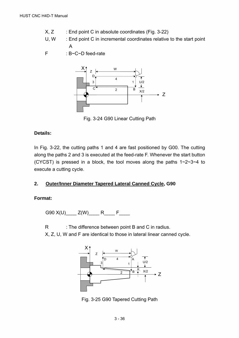
HUST CNC H4D-T Manual
3 - 36
X, Z : End point C in absolute coordinates (Fig. 3-22)
U, W : End point C in incremental coordinates relative to the start point
A
F : B~C~D feed-rate
Fig. 3-24 G90 Linear Cutting Path
Details:
In Fig. 3-22, the cutting paths 1 and 4 are fast positioned by G00. The cutting
along the paths 2 and 3 is executed at the feed-rate F. Whenever the start button
(CYCST) is pressed in a block, the tool moves along the paths 1~2~3~4 to
execute a cutting cycle.
2. Outer/Inner Diameter Tapered Lateral Canned Cycle, G90
Format:
G90 X(U)____ Z(W)____ R____ F____
R : The difference between point B and C in radius.
X, Z, U, W and F are identical to those in lateral linear canned cycle.
Fig. 3-25 G90 Tapered Cutting Path
X
Z
Z W
A
BC
D 4
1
2
3 U/2
X/2R
A
X
ZBC
D Z W
41
2
3 U/2
X/2

3 G/M Codes
3 - 37
Details:
When using incremental coordinates, the signs (+/-) of U and W are determined
by the tool's direction of movement. If the direction is positive, the increment of U
and W is (+), and vice versa. R value is as Fig. 3-26.
Fig. 3-26 G90 Cutting Path and Direction
3. Thread Cutting Fixed Cycle, G92
The advantage of the G92 block is that it functions as four G32 blocks.
Format:
G92 X(U) ___ Z(W) ___ I___ K___ L___ Q ___ F ___ E ___
X, Z : End point C in absolute coordinates
U, W : End point C in incremental coordinates
F : Thread pitch (metric)
E : Number of threads per inch range from 1.0-100.0. This setting
shall not appear when an F setting is given.
I : The axial travel length on X-axis for ending of the thread cutting.
If K ≠0, “I” will be omitted and regarded as 2*K (i.e. ending of the
thread cutting at 45°).
K : The axial distance on Z-axis from the start point to the end point
for the end of thread cutting.
1. U-,W-,R- W
U/2
R
2. U+,W-,R+
W
U/2
R
3. U-,W-,R+
U/2
And |R| < |U/2|
4. U+,W-,R-
R U/2
And |R| < |U/2|
X
Z

HUST CNC H4D-T Manual
3 - 38
L : Multiple-thread setting. Range:1~9. For G92 only.
”L” is a modular value and valid all the time once it is set. If L and
"Q" are set at the same time, the L-value will be regarded as
invalid.
Q : Offset setting of the thread initial angle. Range: 0~359. For G92
only.
Fig. 3-27 G92 Linear Thread Cutting Canned Cycle
Details:
(1) The range of the thread lead and the speed limit of the spindle are same as
G32 (thread cutting).
(2) Whenever the start button (CYCST) is pressed in a block, the tool moves
along the paths 1~2~3~4 to execute a cutting cycle.
(3) Subject to the restrictions of G32.
(4) Where a feed hold command is given during the cutting, the linear thread
cutting canned cycle does not stop until the cutting on path 3 is complete.
4. Tapered Thread Cutting Canned Cycle, G92
Format:
G92 X(U) _____ Z(W) _____ R _____ L___ Q ___ F _____ E_____
R : The difference between point B and C in radius.
X, Z, U, W, L, Q, F, E are identical to those of the linear thread cutting
canned cycle.
Description of the tapered thread cutting is identical to linear thread cutting.
A
X
Z
BC
D Z W
4
1
2
3 U/2
X/2
F

3 G/M Codes
3 - 39
Fig. 3-28 G92 Tapered Thread Cutting Canned Cycle
5. Face Cutting Fixed Cycle, G94
Format:
G94 X(U)____ Z(W)____ F____
X, Z : End point C in absolute coordinates.
U, W : End point C in incremental coordinates relative to the start point
A.
F : B~C~D feed-rate.
Fig. 3-29 G94 Linear Traversed Cutting Path
In Fig. 3-27, the cutting paths 1 and 4 are fast positioned by G00. The cutting
along paths 2 and 3 is executed at the feed-rate F. Whenever the start button
(CYCST) is pressed in a block, the tool moves along the paths 1~2~3~4 to
execute a cutting cycle.
6. Face Cutting Fixed Cycle, G94
Format:
X
Z
Z W
B
C
A
D
2
3
4 U/2
X/2
X
Z
Z W
A
B
C
D 4
1
2
3 U/2
X/2R

HUST CNC H4D-T Manual
3 - 40
G94 X(U)____Z(W) ____R____F____
R : The difference between point B and C in radius.
X, Z, U, W and F are identical to those of the linear traversed canned cycle.
Fig. 3-30 G94 Tapered Traversed Cutting Path
When using incremental coordinates, the signs (+/-) of U and W are determined
by the tool's moving directions. If the moving direction is positive, the increment
of U and W is (+), and vice versa. R value is as Fig. 3-31.
Fig. 3-31 G94 cutting Path and Direction
Note that G90, G94, G92 are modal codes and all the values for X(U), Z(W) and
R remain valid unless they are redefined or another G-command is given.
As shown in Fig. 3-32, if the length of movement on Z-axis is fixed, the canned
cycle is repeated merely by executing the X-axis positioning command.
X
Z
Z W
B
C
A
D
1
2
3
4 U/2
X/2R
66
8/216/2
24/2 26/2
X
Z
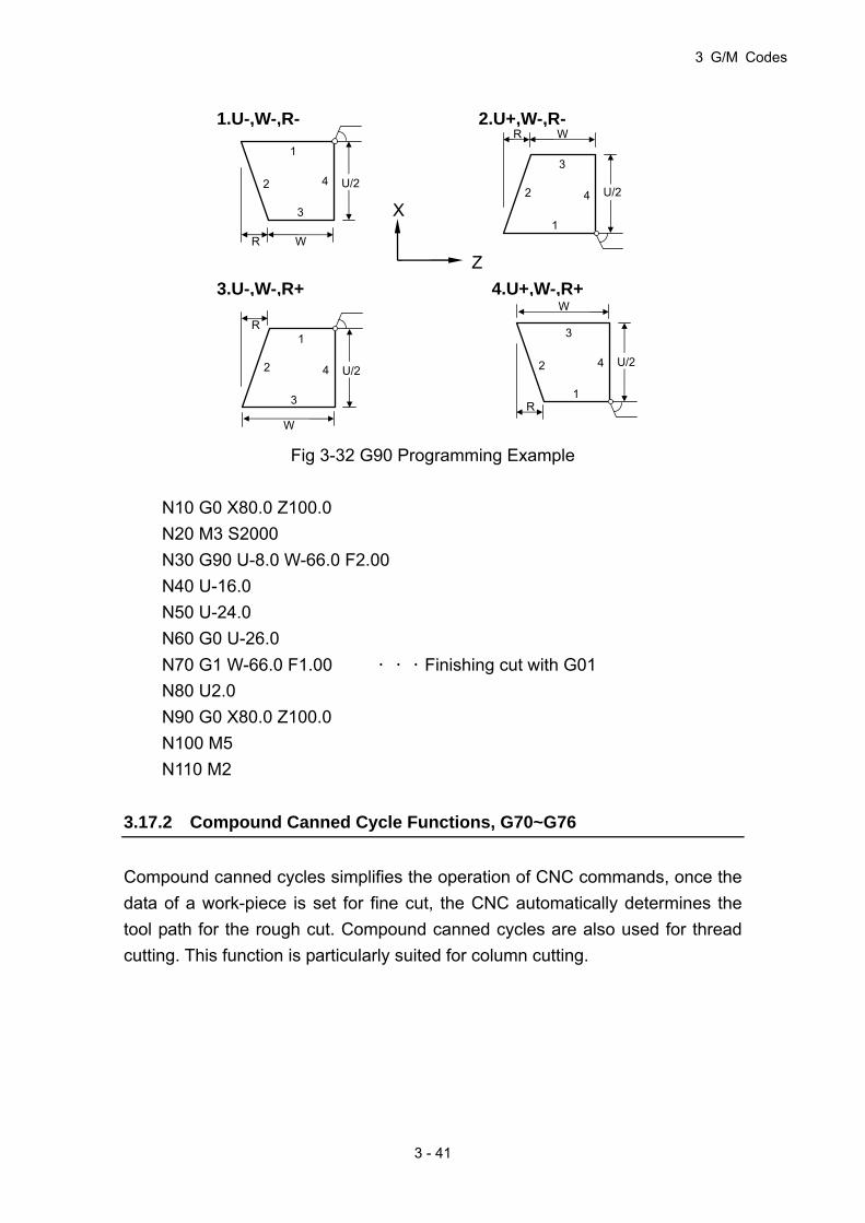
3 G/M Codes
3 - 41
Fig 3-32 G90 Programming Example
N10 G0 X80.0 Z100.0
N20 M3 S2000
N30 G90 U-8.0 W-66.0 F2.00
N40 U-16.0
N50 U-24.0
N60 G0 U-26.0
N70 G1 W-66.0 F1.00 ...Finishing cut with G01
N80 U2.0
N90 G0 X80.0 Z100.0
N100 M5
N110 M2
3.17.2 Compound Canned Cycle Functions, G70~G76
Compound canned cycles simplifies the operation of CNC commands, once the
data of a work-piece is set for fine cut, the CNC automatically determines the
tool path for the rough cut. Compound canned cycles are also used for thread
cutting. This function is particularly suited for column cutting.
1.U-,W-,R-
1
2
3
4 U/2
R W
2.U+,W-,R-
1
2
3
4 U/2
R W
3.U-,W-,R+
3
2
1
4 U/2
R
W
4.U+,W-,R+
3
2
1
4 U/2
R
W
X
Z

HUST CNC H4D-T Manual
3 - 42
1. Finishing Cycle, G70
Functions and Purposes:
After a work-piece undergoes rough cut with G71, G72 or G73, G70 is used for
fine cut of the work-piece to ensure its precision.
Format:
G70 P(ns)____ Q(nf)____
P(ns) : The number of the first block for a fine cut cycle.
Q(nf) : The number of the last block for a fine cut cycle.
Details:
(1) The F, S, and T functions of G71, G72, G73 and previous blocks are
applicable to G70. wherer F, S, or T is changed in the blocked from P(ns) to
Q(nf), the changed values praveil.
(2) When G70 is executed, the tool returns to the start point and reads the next
block.
2. Longitudinal Rough Cutting Cycle, G71
Format:
G71 U(△d)____ R(e)____
G71 P(ns)____ Q(nf)____ U(△u)____ W(△w)____ F(f)____ S(s)____
T(t)____
N(ns) .....
.....
.....
N(nf) .....
G00 X__ Z__ ;Tool move back
Txxxx ;Change tool (fine cutting)
G00 X__ Z__ ;Move to the start position of Canned Cycle
G70 P(ns) Q(nf) ;Fine cutting

3 G/M Codes
3 - 43
Parameters:
In Fig. 3-33, the fine cut path is A~A1~B. A~C is the distance reserved for fine
cut tool retraction. The cutting depth is U(△d). The amount of the material to be
removed for fine cutting is (△u/2) and (△w). The amount of retraction after each
cut is R(e). The path of the final rough cut is parallel to the path of the fine cut.
The definition of command groups in the program format is described below:
Fig. 3-33 Tool Path of G71 Rough Cut Canned Cycle
U(△d) : Cutting depth (radius programming ,+).
If not specified, the parameter "G71, G72 Feeding Amount" is
used.
R(e) : Amount of retraction after each rough cut (radius
programming).
If not specified, the parameter "G71, G72 Retraction Amount" is
used.
P(ns) : The number of the first block for a fine cut cycle.
Q(nf) : The number of the last block for a fine cut cycle.
U(△u) : Amount of material to be removed for fine cut, X-axis.
W(△w) : Amount of material to be removed for final cut, Z-axis.
F(f),S(s),T(t): F = feed-rate. S = spindle speed, T = tool selection.
The F, S, and T functions of G71 and previous blocks are
applicable to G71, but all F, S, and T functions from N(ns) to
N(nf) are not applicable to G71. They are only applicable to
the fine cut command G70.
e
(G00)
(F)
A
C
A1
B
G00-fast feeding at
F– rate
G70 fine cut (program) path
d
U/2
W
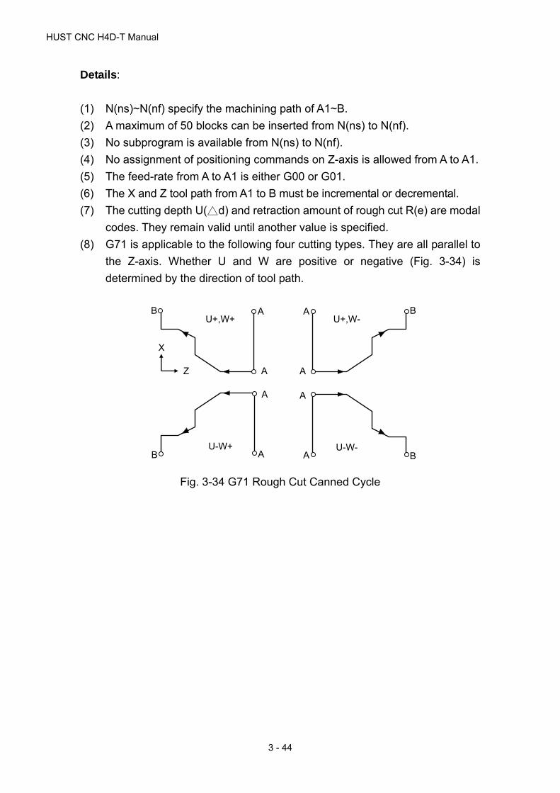
HUST CNC H4D-T Manual
3 - 44
Details:
(1) N(ns)~N(nf) specify the machining path of A1~B.
(2) A maximum of 50 blocks can be inserted from N(ns) to N(nf).
(3) No subprogram is available from N(ns) to N(nf).
(4) No assignment of positioning commands on Z-axis is allowed from A to A1.
(5) The feed-rate from A to A1 is either G00 or G01.
(6) The X and Z tool path from A1 to B must be incremental or decremental.
(7) The cutting depth U(△d) and retraction amount of rough cut R(e) are modal
codes. They remain valid until another value is specified.
(8) G71 is applicable to the following four cutting types. They are all parallel to
the Z-axis. Whether U and W are positive or negative (Fig. 3-34) is
determined by the direction of tool path.
Fig. 3-34 G71 Rough Cut Canned Cycle
U+,W+B A
A
X
Z
U+,W-B A
A
U-W+B A
A
U-W-B A
A

3 G/M Codes
3 - 45
Programming example of G70, G71 compound canned cycle:
Fig. 3-35 Programming Example of G71, G70 Compound Canned Cycle
G28 W0.
T0202
M3 S3000
G00 X100.000
Z140.000
G71 U7.000 R1.000
G71 P100 Q200 U4.000 W2.000 F2.00
N100 G01 X25.0 F1.50
W-10.000
X50.000 W-20.000
W-20.000
X75.000 W-15.000
W-15.000
N200 X100.000 W-15.000
G00 X110.
Z150.
T0303
G00 X100.
Z140.
G70 P100 Q200
M05 S0
M30
255075100
G70, G71 start/end point
(100/2,140)
45 15 15 15 20 20 10
X
Z 2
2
7 (cutting depth) 1 (retraction)
Reserved for fine cut
G70 fine cut path
Safe point to change tool

HUST CNC H4D-T Manual
3 - 46
3. Face Rough Cutting Cycle, G72
Functions and Purposes:
Calls a forming program and calculates tool path automatically while executing a
transversed rough cutting.
Format:
G72 W(△d) ___ R(e) ___
G72 P(ns)___ Q(nf)___ U(△u)___ W(△w)___ F(f)___ S(s)___ T(t)___
N(ns) .....
.....
.....
N(nf) .....
G00 X__ Z__ ;Tool move back
Txxxx ;Change tool (fine cutting)
G00 X__ Z__ ;Move to the start position of Canned Cycle
G70 P(ns) Q(nf) ;Fine cutting
Fig. 3-36 Cutting Path of G72 Compound Canned Cycle
As shown in Fig. 3-36, all functions of G72 are same as G71, except that the cycle
path is parallel to the X-axis.
Details:
(G00)
(F)
AC
A1
B
G00-fast feeding at F – rate
G70 fine cut (program) path
e
dW
U/2

3 G/M Codes
3 - 47
(1) N(ns)~N(nf) define the machining path of A1~B.
(2) No assignment of positioning commands on X-axis is allowed from A to A1.
(3) The feed-rate from A to A1 is either G00 or G01.
(4) The X and Z tool path from A1 to B must be incremental or decremental.
(5) No subprogram is available from N(ns) to N(nf).
(6) G72 is applicable to the following four cutting types. They are all parallel to
X-axis. Whether U and W are positive or negative (Fig. 3-37) is determined
by the direction of tool path.
Fig. 3-37 Cutting Path of G72 Compound Canned cycle
Example:G72, G70 compound canned cycles
Fig. 3-38 Programming Example of G72, G70 Compound Canned Cycles
X
Z
U+,W-
B
A A1
U-,W-
B
A A1
U+,W+
B
AA1
U-,W+
B
AA1
255075100
45 15 15 15 20 20
X
Z 2
2
Reserved for fine cut
G70 fine cut path
(108/2,130)
G72, G70 start/end point
10 (cutting depth) 1 (retraction)
Tool change start point
HUST CNC H4D-T Manual
3 - 48
G28 W0.
T0202
M3 S2000
G00 X108.000 Z130.000
G72 W10.000 R1.000
G72 P100 Q200 U4.0 W2.0 F3.00
N100 G00 Z45.000
G01 X75.000 W15.000 F1.50
W15.000
X50.000 W15.000
W20.000
N200 X25.000 W20.000
G00 X110.
Z140.
T0303
G00 X108.
Z130.
G70 P100 Q200
M05 S0
M30
4. Formed Material Rough Cutting Cycle, G73
Functions and Purposes:
To save machining time, G73 is used to cut a work-piece that has been
machined in a rough cut, forging or casting process and formed with a shape
similar to the finished-product.
Format:
G73 U(△i)___ W(△k)___ R(d)___
G73 P(ns)___ Q(nf)___ U(△u)___ W(△w)___ F(f)___ S(s)___ T(t)___
N(ns) .....
.....
.....
N(nf) .....

3 G/M Codes
3 - 49
G00 X__ Z__ ;Tool move back
Txxxx ;Change tool (fine cutting)
G00 X__ Z__ ;Move to the start position of Canned Cycle
G70 P(ns) Q(nf) --- ;Fine cutting
Parameters:
U(△i) : Cutting amount on X-axis. (radius programming)
If not defined, the parameter "G73 Total Cutting Amount " is used.
W(△k) : Cutting amount on Z-axis.
If not defined, the parameter "G73 Total Cutting Amount" is used.
R(d) : Rough Cutting Cycles
I.e. times of cuts required to reach the defined cutting depth on X
and Z-axes. If not defined, the parameter "G73 Cutting Cycles"
is used.
P(ns) : The first block number of a fine cut cycle.
Q(nf) : The last block number of a fine cut cycle.
U(△u) : Amount of material to be removed for fine cut, X-axis.
W(△w) : Amount of material to be removed for final cut, Z-axis.
F(f),S(s),T(t): F = feed-rate, S = spindle speed, T = tool selection.
The F, S, and T functions of G73 and previous blocks are applicable to G73,
but all F, S, and T functions from N(ns) to N(nf) are not applicable to G73.
They are only applicable to the fine cut command G70.
Fig. 3-39 Cutting Path of G73 Compound Canned Cycle
B
A1
A
12
3
CA~ C retraction distance
1,2,3 feed sequence
k+w
i+u/2
u/2
w

HUST CNC H4D-T Manual
3 - 50
Details:
(1) N(ns)~N(nf) define the machining path of A←A1←B.
(2) A maximum of 50 blocks can be inserted from N(ns) to N(nf).
(3) No subprogram is available from N(ns) to N(nf).
(4) The tool returns to A when the cycle finishes.
(5) The cutting amount U(△i), W(△k) and the cutting cycles R(d) are modal
codes. They remain valid until another value is defined.
Example: G70, G73 compound canned cycles
Fig. 3-40 Programming example of G70, G73 Compound Canned Cycles
G28 W0.
T0202
M3 S3000
G00 X120.000 Z150.000
G73 U14.000 W14.000 R3
G73 P100 Q200 U4.000 W2.000 F2.00
N100 G00 X25.000 W-20.000
G01 X50.000 W-20.000 F1.5
W-20.000
X75.000 W-15.000
W-15.000
N200 G01 X100.000 W-15.000
G00 X130.
255075100
45 15 15 15 20 20 20
X
Z 2
2
Reserved for fine cut
G70 fine cut path
(120/2,150)
G73, G70 start point
First feeding
4.67=14/3 Cutting depth

3 G/M Codes
3 - 51
Z160.
T0303
G00 X120.
Z150.
G70 P100 Q200
M5 S0
M30
5. Face Cut-Off Cycle, G74
Functions and Purposes:
G74 command automatically performs a fixed loop at the end of the workpiece
via commands such as coordingate of groove end, cutting depth, tool retract
depth etc.
Format:
G74 R(e)___
G74 X(U)___ Z(W)___ P△i___ Q△k___ R△d___ F___
R(e) :Amount the tool move backward when after Z cutting △k
X :Absolute positioning command on X-axis
Z :Absolute positioning command on Z-axis
U :Incremental positioning command on X-axis
W :Incremental coordinates on Z-axis
P△i :Amount the each movement of X canned cycle.
Q△k :Z cutting of the each segment
R△d :Amount the tool move backward when X end of cutting
F :Cutting speed feed-rate
(1) Input of a Z or W parameter is a must
(2) IF R (e) tool extraction parameter is not given, tool extraction depth shall be
set using the setting of parameter G74 or G75.
(3) Total cutting distance must be greater than respective cutting distances.
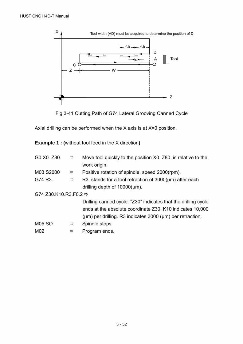
HUST CNC H4D-T Manual
3 - 52
Fig 3-41 Cutting Path of G74 Lateral Grooving Canned Cycle
Axial drilling can be performed when the X axis is at X=0 position.
Example 1 : (without tool feed in the X direction)
G0 X0. Z80. Move tool quickly to the position X0. Z80. is relative to the
work origin.
M03 S2000 Positive rotation of spindle, speed 2000(rpm).
G74 R3. R3. stands for a tool retraction of 3000(μm) after each
drilling depth of 10000(μm).
G74 Z30.K10.R3.F0.2
Drilling canned cycle: ”Z30” indicates that the drilling cycle
ends at the absolute coordinate Z30. K10 indicates 10,000
(μm) per drilling. R3 indicates 3000 (μm) per retraction.
M05 SO Spindle stops.
M02 Program ends.
Z
X
A
D
C e Tool
Tool width (AD) must be acquired to determine the position of D.
k k
Z W

3 G/M Codes
3 - 53
Fig. 3-42
Example 2 : (with tool feed in the X direction)
G0 X0. Z80. Move tool quickly to the position X0. Z80. is relative to the
work origin.
M03 S2000 Positive rotation of spindle, speed 2000(rpm).
G74 R3. R3. stands for a tool retraction of 3000(μm) after each
drilling depth of 10000(μm)
G74 X2.Z30.P400 Q10000 R1. F0.5
Grooving canned cycle: “Z30.” Indicates the drilling cycle
ends at absolute coordinate 30. in the Z-direction; “X2.”
Indicates the end coordinates of cycling movements in the
X-direction are: 2.; “P400” indicates a 200 (μm) movement
per cycle in the X-direction; Q10000 indicates 10000(μm)
per drilling; “R1.” Indicates tool retraction of 500(μm) in the
X-direction when the cutting reaches end position.
(Diameter specification)
M05 SO Spindle stops.
M02 Program ends.
6. Longitudinal Cut-Off Cycle, G75
Functions and Purposes:
The G75 function is the same as G74 except that the positioning direction of G75
is on the X-axis.
10 10
3
A 30
TOOL
80
X
Z

HUST CNC H4D-T Manual
3 - 54
Format:
G75 R(e)___
G75 X(U) ___ Z(W) ___P△i ___ Q△k ___ R△d ___F
Parameters:
R(e) :Amount the tool move backward when after X cutting △I. (Diameter
specification)
X :Absolute positioning command on X-axis
Z :Absolute positioning command on Z-axis
U :Incremental positioning command on X-axis
W :Incremental coordinates on Z-axis
P△i :Amount the each movement of X canned cycle. (Diameter
specification)
Q△k :Z cutting of the each segment(Integer μm specification)
R△d :Amount the tool move backward when Z end of cutting (Integer μm
specification)
F :Cutting speed feed-rate
Details:
1. Input of a Z or W parameter is a must
2. IF R (e) tool extraction parameter is not given, tool extraction depth shall be
set using the setting of parameter G74 or G75.
3. Total cutting distance must be greater than respective cutting distances.
A
Fig. 3-43 Cutting Path of G75 Traverse Grooving Canned Cycle
Z
X Tool
D
k/2
U/2
X/2
Tool width (AD) must be acquired to
determine the position of D.
C
k/2
k/2
A
3 G/M Codes
3 - 55
Example 1 : (without tool feed in the Z direction )
N10 G0 X80.0 Z0.O Moves tool quickly to the home position of
workpiece X80. Z0.
N20 M03 S2000 Spindle CW, speed 2000(rpm).
N30 G75 R1. R1. indicates a 500(μm) tool retraction after
each drilling depth of 2500(μm).
N40 G75 X60. P5. F0.5 Drilling cycle: “Z60.” Indicates end of drilling
cycle is at absolute coordinate 60. in the
Z-direction. P5. stands for 2500 (μm) per
drilling. (Diameter specification)
N50 M5 S0 Spindle stops.
N60 M2 End of program.
Example 2 : (with tool feed in Z direction)
N10 G0 X80.0 Z0.O Quickly move tool to X80. Z0 position relative
to the work origin
N20 M03 S2000 Positive rotation of spindle, speed 2000(rpm).
N30 G75 R2. R2. stands for a tool retraction of 1000(μm)
after each drilling depth of 2500 (μm).
N40 G75 X60.Z3.P5. Q500 R1.F0.5
Groove cutting cycle: “X60.” indicating drilling
cycle ends at the absolute coordinate X60.
“Z3.” Indicates that the cycle ends at
coordinate Z3. “P5.” stands for a drilling depth
of 2500 (μm) for each drilling cycle. Q0.5
stands for Z-direction movement per cycle is
500 (μm). “R1.” indicates tool retraction of
1000 (μm) in Z-direction after reaching the end
position. (diameter specification)
N50 M5 S0 Spindle stop.
N60 M2 end of program.
7. Compound Thread Cutting Canned Cycle, G76
Functions and Purposes:

HUST CNC H4D-T Manual
3 - 56
G76 specifies the start point and end point of a thread cutting. This command
can be entered at any angle. A fixed number of loops are cut for every cycle with
the same cross-section. Thread end point coordinate and specification of
slanting height are considered. It is also capable of performing thread cutting in
various directions.
Format:
G76 P(m)(r)(a)___ Q(△d min)___ R(d)___
G76 X(U)____ Z(W)____ R(i)____ P(k)____ Q(△d)____ F(l)____ E____
Fig. 3-44 G76 Compound Thread Cutting Canned Cycle
Parameters:
m : Fine cut times (2-digit, 01~99)
If not defined, parameter "G76 Fine Cut Times" is used.
r : Chamfering settings (2 digits)
Length of chamfering = 0.1 × chamfering settings (r) × thread pitch.
If not defined, the parameter "Chamfering Settings" is used.
a : Tool-tip angle (0°-90°).
The available angles are 0°, 5°,10°,15°,…to 90°. If not defined,
the parameter "Tool-tip Angle" is used.
m, r, and a are defined simultaneously by the command code P.
For m=2, r=12, a=60°, then the command is G76 P021260.
Q(△d min): Minimum cutting amount (integer μm)
When the cutting amount of the nth cutting (△d n - △d n-1)
<△d min, the cutting will resume with △d min as the minimum
C
X
Z
E A
D B
U/2
X/2
Z
i r
(G00)
(G00)
(F)(G00)
W
d K

3 G/M Codes
3 - 57
cutting amount. If no minimum cutting amount is defined, the
parameter "Minimum Cutting Depth" is used.
R(d) : Amount of material to be removed for the fine cut
If not defined, the parameter " Reserved Thread Depth" is
used.
X, Z : Absolute coordinates of cutting end point (D).
U, W : Incremental coordinates of the cutting end point ( D).
R(i) : Radius difference of thread part (i=0 indicates normal linear
thread cutting).
P(k) : Thread height (radius programming on X-axis, unit: integerμm)
Q(△d) : First cutting depth (radius programming, unit: integerμm)
F(l) : Thread pitch, (same as G32)
E : Number of threads per inch; range: 1.0-100.0. This setting shall
not appear when an F setting is given.
Details: ( Fig 3-45、Fig 3-46 )
(1) What must be noted is that length of the path DE (U/2) must be greater than
the length of the chamfer.
(2) The fine cut times m,chamfering settings r,tool-tip angle a, minimum cutting
amount Q (△d min) and reserved thread depth R(d) are modal codes. They
remain valid until another value is defined.
(3) The feed-rate between C and D is defined by F and fast feeding is applied
to other paths. The (+)(-) values of the increments in Fig. 3-39 are as
follows:
U, W : Negative (determined by the directions of AC and CD).
R : Negative (determined by the directions of AC).
Fig. 3-45 Cutting Description
TOOL
d
d n k
d

HUST CNC H4D-T Manual
3 - 58
(4) The thread height K is acquired from the thread pitch and the tool nose
angle. The formula is:
Thread height k= (pitch/2) / Tan (angle/2)
Tan (angle/2),acquired from the trigonometric table.
Ex: If tool nose angle a=60°, Thread pitch F(l)=2 mm.
Fig. 3-46
Thread height k = (2/2) / Tan(60/2)
= (1) / Tan 30 = (1)/0.5774 = 1.732
The first cutting depth (cutting amount) is △d,the nth cutting depth is △d n, the
cutting amount will decrease progressively every time. Note that n should not
exceed 30. Otherwise, an alarm will be generated. In this case, please use the
normal thread cutting.
Example:
If tool nose angle a=60°, Thread pitch F (l)=2 mm.
as shown in the above example, thread height k= 1.732
X = 20 - 2 × 1.732 = 16.536
Fig. 3-47 G76 Programming Example
N10 G0 X30.0 Z60.0
N20 M03 S2000
N30 G76 P011060 Q100 R0.200
Thread depth, k
Thread pitch (1)
30 30
X
Z20 16.536
10 502
1.732

3 G/M Codes
3 - 59
N40 G76 X16.536 Z10.000 P1732 Q900 F2.00
N50 M05
N60 M02
Notes on thread cutting are identical to G32 and G92. The chamfering settings
are also applicable to G92 thread cutting canned cycle.
8. Notes on Compound Canned Cycle (G70~G76):
. Every command of a compound canned cycle must contain correct P, Q, X,
Z, U, W and R values.
. In G71, G72, G73 blocks, the block defined by P must contain either G00 or
G01.Otherwise, alarm will be generated.
. G70, G71, G72, and G73 are not allowed in MDI mode. Otherwise, an
alarm is triggered.
. In G70, G71, G72, or G73, no M98 (call subprograms) and M99 (quit
subprograms) are applicable to blocks defined by P and Q.
. When executing G70~G73, the serial numbers defined by P and Q should
not be the same.
. In G70, G71, G72, and G73, chamfering and R angle should not be used to
terminate the last positioning command used for fine cut shaping blocks
defined by P and Q.
3.18 G50 Coordinate system & Spindle clamp speed setting
1. The setting function fo the maximum spindle speed (G50) normally
goes with setting function of the constant surface cutting (G96).
Format:
G50 S____
S : Max. spindle speed (rpm or rev/min)
2. Working coordinate offset function. For continuous process of
multiple workpieces, work origin can be set via continuous offset
setting of tool start point.
HUST CNC H4D-T Manual
3 - 60
Format:
(1) G50 U _____(X -direction offset)。
(2) G50 W _____(Z -direction offset)。
Example:
O001(Main program number)
N10 G10 P500 A1 B0 (X –direction work coordinate offset clearing)
N20 G10 P500 A3 B0 (Z –direction work coordinate offset clearing)
N30 T01
N40 M98 P02 L5 (Call for O002 subprogram, successively for 5
times)
N50 M99
O002(number of subprogram)
N1 G50 W10. (10mm offset of tool start point each for every time)
N2 G01 U-10.
N3 G00 U10.
N2 M99
Description:
(1) Please give “G10 P500 A1 B0”, and “G10 P500 A3 B0” at the
beginning of program.
(2) The “L suffix” of an M98 command indicates number of offsets to be
performed. (See description of M98 command).
3.19 Constant Surface Speed Control ON, G96
Format:
G96 S____
S : Surface cutting speed (m/min)
The surface cutting speed refers to the relative velocity between the tool-tip and
cutting point (on the surface) of the rotating work-piece. A tool has its advised
surface cutting speed range for optimizing the cutting result. G96 is used to

3 G/M Codes
3 - 61
control the surface cutting speed. The relationship between the surface cutting
speed, work-piece diameter and spindle rotation speed is expressed by:
V=πDN
V : The surface cutting speed is the S value of G96.
D : Diameter of the surface is sut, m.
N : Spindle rotation speed, rev/min.
When the surface cutting speed is constant and the tool cuts the surface inwards,
D will become lesser and N will become greater. Hence the max. rotation speed
must be limited using G50 S__. Once this limit is reached, the speed will not
increase any more.
Ex: N10 G50 S2000 ...Max. rotation speed of the spindle is 2000 rpm.
N20 G96 S200 ...The constant surface cutting speed is 200 m/min.
3.20 Constant Surface Speed Control OFF, G97
Format:
G97 S____
This function maintains the spindle speed defined by S. It cancels the constant
surface cutting speed at the same time.
3.21 Feed-rate Setting, G98, G99
G98 : Feed per minute, mm/min
G99 : Feed per revolution, mm/rev
The feed-rate F in H4D-T turner series is defined by G98 and G99. G99 is the
default value. The conversion formula is:
Fm = Fr * S
Fm : Feed per minute, mm/min.
Fr : Feed per revolution, mm/rev.

HUST CNC H4D-T Manual
3 - 62
S
R
Pause time
S : Spindle speed, rev/min.
3.22 Inch/Metric Measurement Mode , G20, G21
Format:
G20 -- System measurement in INCH mode
G21 -- System measurement in METRIC mode
3.23 Deep Hole Drilling Cycle (Z axis) G83,G80
Format:
G83 Z(W)___ Q___ R___ F___ ; Deep hole drilling cycle
G80 ; Fixed cycle for drilling cancel
Parameters:
Z(W) :Point the hole position with absolute or increment
Q :Each depth of drilling (Unit: μm , Q10000=10mm)
※ If Q with no values that drilling motion will finish one time.
R :Point of reference with go forward or move backward
※ Absolute position
※ If R with no values that it will according to now Z coordinates be
R values.
F :Drilling speed feed-rate (mm/rev)
Fig 3-48
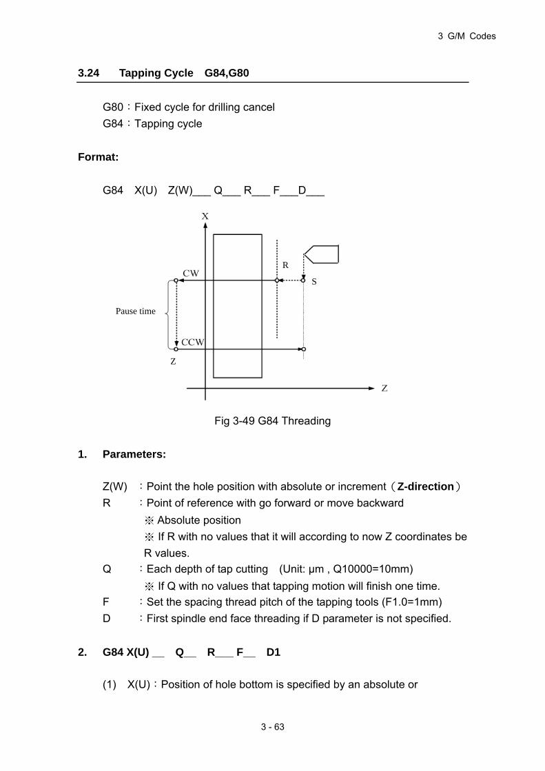
3 G/M Codes
3 - 63
3.24 Tapping Cycle G84,G80
G80:Fixed cycle for drilling cancel
G84:Tapping cycle
Format:
G84 X(U) Z(W)___ Q___ R___ F___D___
Fig 3-49 G84 Threading
1. Parameters:
Z(W) :Point the hole position with absolute or increment(Z-direction)
R :Point of reference with go forward or move backward
※ Absolute position
※ If R with no values that it will according to now Z coordinates be
R values.
Q :Each depth of tap cutting (Unit: μm , Q10000=10mm)
※ If Q with no values that tapping motion will finish one time.
F :Set the spacing thread pitch of the tapping tools (F1.0=1mm)
D :First spindle end face threading if D parameter is not specified.
2. G84 X(U) __ Q__ R___ F__ D1
(1) X(U):Position of hole bottom is specified by an absolute or
R
S
Z
Pause time
HUST CNC H4D-T Manual
3 - 64
incremental value (X-direction)
(2) D=1:Threading of second spindle lateral face
(3) Other parameters are the same as above
3. G84 Z(W) __ Q__ R___ F__ D2
(1) Z(W):Position of hole bottom is specified by an absolute or
incremental value (Z-direction)
(2) D=2:Threading of third spindle end face
(3) Other parameters are the same as above
G84 and G80 are used in pairs. If G80 is missing, program will report an Err18.
G84 Z-axis application example:
N10 M70(third spindle switched as servo-spindle mode)
N20 T1
N30 G0 X-20.C0.
N40 Z3.
N50 G84 Z-20.F1.R2.D2
N60 C60.
N70 C120.
N80 G80
N90 M71(third spindle switched back to main spindle mode)
N100G0 Z20.
N110 M2
G84 X –axis application example:
N10 M60(Second spindle switched as servo-spindle mode)
N20 T1
N30 G0X5.C0.
N40 Z3.
N50 G84U-10.F1.R4.D1
N60 C60.
N70 C120.
N80 G80
N90 M61(Second spindle switched back to spindle mode)
N100 M02

3 G/M Codes
3 - 65
3.25 Auxiliary Functions, M-code, S-code
The auxiliary function M-code is comprised of the letter M and 2 digits attached
behind (M-codes for general), different codes represents different functions as
shown below:
Currently, H4D-T Series provides the following M-codes:
Table 3-10
M-CODE Function
M00 Program Suspension.
M01 Selective stop
M02 Program End.
M03 Spindle rotates in normal direction
M04 Spindle rotates in reversed direction
M05 Spindle stops
M08 Coolant ON.
M09 Coolant OFF.
M10 Spindle chuck tightened
M11 Spindle chuck loosened
M12 Tailstock forward
M13 Tailstock backward
M15 Count plus 1
M16 Count clear (to zero)
M30 Program end
M33 Workpiece Collector Protrude
M34 Workpiece Collector Extract
M35 Tailstock Chuck Clamp
M36 Tailstock Chuck Release
M40 Chip Remove CW
M41 Chip Remove CCW
M42 Chip Remove Stop
M43 Feeder Start
M45 Select Skip Start
M46 Select Skip Close
M47 The Spindle should rotate after releasing the Chuck
M48 When releasing the Chuck, prohibit the spindle rotation.
M50 Set Spindle 1 to Servo Axis Mode.

HUST CNC H4D-T Manual
3 - 66
M-CODE Function
M51 Set Spindle 1 back to Spindle Mode.
M55 Start in-process Tool offset change instant avail.
M60 Set Spindle 2 to Servo Axis Mode.
M61 Set Spindle 2 back to Spindle Mode.
M63 Spindle 2 CW
M64 Spindle 2 CCW
M65 Spindle 2 Stop
M70 Set Spindle 3 to Servo Axis Mode.
M71 Set Spindle 3 back to Spindle Mode.
M73 Spindle 3 CW
M74 Spindle 3 CCW
M75 Spindle 3 Stop
M80 Enable axial direction without homing
M81 Disable axial direction without homing
M84 Spindle brake hold
M85 Spindle brake release
M98 Call subprogram
M99 Program cycle
M30 Program end
M300 Enable round-angle connection between blocks
M301 Disable round-angle connection between blocks
M362 Switch to Spindle 1
M364 Switch to Spindle 2
M365 Switch to Spindle 3
Using CW, CCW of spindle:
1. M03: First spindle clockwise (CW)
Format:
(1) M03 SXXXX
EX.: M03 S1000 ;Command first spindle to rotate CW at 1000rpm.
(2) M03
If M03 is not followed by an S-code, spindle rpm is not specified;
spindle will rotate CW at the previous speed.
2. M04: First spindle CCW
Format:
(1) M04 SXXXX

3 G/M Codes
3 - 67
EX.: M04 S1000 ;Command first spindle to rotate CCW at 1000rpm
(2) M04
If M04 is not followed by an S-code, spindle rpm is not specified;
spindle will rotate CCW at the previous speed.
The auxiliary function code S-code is for spindle rpm control, maximum setting
range: S999999.
EX: S1000, means 1000 rpm
3.26 Subprogram
Where there are certain fixed programs or command groups in a main program
that demand repeated execution, these commands could be saved in memory
as subprograms, so that the main program could be designed with a simplified
structure. Subprograms can be called out one after another in auto mode.
1. Structure of the Subprogram
The structure of the subprogram is the same as the main program except that
the subprogram ends with an M99 command.
PROGRAM 05 .....Subprogram number
.....Content
.....Content
M99 .....Subprogram ends
If a subprogram is not called by the main program but executed directly by
pressing “CYCST”, the program loops.
2. Execution of the Subprogram
Format:
M98 P _____ L _____
P : Subprogram number
L : Execution times of the subprogram. If not defined, the

HUST CNC H4D-T Manual
3 - 68
subprogram is to be executed only once.
Ex: M98 P05 ..... Execute subprogram No 5 once.
M98 P05 L3 .....Execute subprogram No 5 three times.
Stepwise Call: the main program calls the first subprogram, and the first
subprogram calls a second sub-prgrams. The H4D-T Series controller provides
a maximum of 8 levels stepwise calls: (take for an example of 5 layers)
Fig. 3-50 Subprogram Stepwise Call
The M98 and M99 blocks should not contain any positioning commands, such as
X…, Z… .
3.27 Tool Radius Compensation
3.27.1 Total Offset Compensation Setting and Cancellation
Total offset compensation = Length compensation + Wear compensation
Format:
Table 3-11
Compensation
Set
Compensation Cancel
Without Turret T□□ T00
With Turret T○○□□ T○○00
□□: Compensation number, indicating which set of compensation data
is to be applied.
○○: Tool number, indicating which tool is to be selected.
N1 ...
.
.
N5M98P2
.
.
N31 M2
N1 ...
.
.
N5M98P4
.
.
N32 M99
N1 ...
.
.
N5M98P3
.
.
N32 M99
N1 ...
.
.
N5M98P5
.
.
N32 M99
N1 ...
.
.
.
.
.
N32 M99
PROGRAM 1 PROGRAM 2 PROGRAM 3 PROGRAM 4 PROGRAM 5
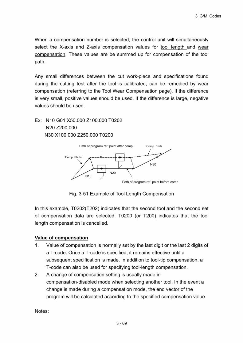
3 G/M Codes
3 - 69
When a compensation number is selected, the control unit will simultaneously
select the X-axis and Z-axis compensation values for tool length and wear
compensation. These values are be summed up for compensation of the tool
path.
Any small differences between the cut work-piece and specifications found
during the cutting test after the tool is calibrated, can be remedied by wear
compensation (referring to the Tool Wear Compensation page). If the difference
is very small, positive values should be used. If the difference is large, negative
values should be used.
Ex: N10 G01 X50.000 Z100.000 T0202
N20 Z200.000
N30 X100.000 Z250.000 T0200
Fig. 3-51 Example of Tool Length Compensation
In this example, T0202(T202) indicates that the second tool and the second set
of compensation data are selected. T0200 (or T200) indicates that the tool
length compensation is cancelled.
Value of compensation
1. Value of compensation is normally set by the last digit or the last 2 digits of
a T-code. Once a T-code is specified, it remains effective until a
subsequent specification is made. In addition to tool-tip compensation, a
T-code can also be used for specifying tool-length compensation.
2. A change of compensation setting is usually made in
compensation-disabled mode when selecting another tool. In the event a
change is made during a compensation mode, the end vector of the
program will be calculated according to the specified compensation value.
Notes:
Path of program ref. point after comp. Comp. Ends
Path of program ref. point before comp.
Comp. Starts
N10 N20
N30
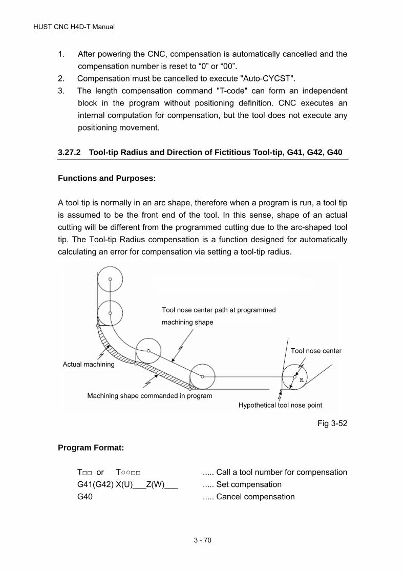
HUST CNC H4D-T Manual
3 - 70
Tool nose center path at programmed
machining shape
Tool nose center
Hypothetical tool nose point
Actual machining
Machining shape commanded in program
1. After powering the CNC, compensation is automatically cancelled and the
compensation number is reset to “0” or “00”.
2. Compensation must be cancelled to execute "Auto-CYCST".
3. The length compensation command "T-code" can form an independent
block in the program without positioning definition. CNC executes an
internal computation for compensation, but the tool does not execute any
positioning movement.
3.27.2 Tool-tip Radius and Direction of Fictitious Tool-tip, G41, G42, G40
Functions and Purposes:
A tool tip is normally in an arc shape, therefore when a program is run, a tool tip
is assumed to be the front end of the tool. In this sense, shape of an actual
cutting will be different from the programmed cutting due to the arc-shaped tool
tip. The Tool-tip Radius compensation is a function designed for automatically
calculating an error for compensation via setting a tool-tip radius.
Fig 3-52
Program Format:
T□□ or T○○□□ ..... Call a tool number for compensation
G41(G42) X(U)___Z(W)___ ..... Set compensation
G40 ..... Cancel compensation

3 G/M Codes
3 - 71
Before using G41 and G42, inform the NC unit which tool-no. is to be used. The
application is totally dependent to the tool path and the relative position of the tool.
As shown in Fig. 3-53, looking forward along the tool path, use G42 if the tool tip
radius is on the right side of the tool path (radius right side offset compensation);
use G41 if the tool tip radius is on the left side of the tool path (radius left side
offset compensation)
Fig 3-53 Application of G41 and G42
Tool-tip and assumed tool-tip direction
When executing tool-tip radius compensation, the radius and arc must be
accurate; otherwise, the cutting result will not be precise. Manufacturers of
disposable tools always provide accurate tool-tip radius data. The radius data
are to be entered in the "R" field on the Tool Length Compensation page (unit:
mm).
Besides the tool-tip radius, the direction of fictitious tool-tips must be acquired (refer
to the position of P in Fig. 3-54). The direction is defined by integers 0~9 (Fig. 3-44).
In the system with tools on the top (rear) holder, the direction 3 is for outer diameter
cutting, while the direction 2 is for inner diameter cutting. The data of fictitious tool-tip
direction are to be entered in the "T" field on the Tool Length page.
Once these two data are acquired, the control unit compensates for the tool-tip
properly by calculating "R" and "T" values internally after giving the tool-tip
radius compensation command.
Direction of tool path
G42 (right side)
Direction of tool path
G41 (left side)
X
ZWork piece

HUST CNC H4D-T Manual
3 - 72
Fig 3-54 Fictitious Tool-tip Direction
Tool-tip point and compensation operation
(1) Process using center of tool-tip radius as the starting point:
Fig 3-55
Direction-1 Direction-2
Direction-3 Direction-4
Direction-5 Direction-6
Direction-7 Direction-8
Direction-0,9
2 1 6
7 0 9 5
83 4
Or simplified as below
X
Z
End Point
Start point
Nose R center path with toolnose radius compensation
Programmed path ormachining shape with tool nose radius compensation
Machining shape with notool nose radius compensation

3 G/M Codes
3 - 73
End Point
Start point Machining shape with no toolnose radius compensation
Programmed path ormachining shape with tool nose radius compensation
Nose R tool nose point path with tool nose radius compensation
(2) Process using tool-tip as the starting point:
Fig 3-56
Start of tool-tip radius compensation:
When compensation is disabled and all the following conditions are met, tool-tip
radius compensation starts:
1. Executing a G41.G42 command.
2. Executing a move command excluding the arc commend. When used
during a G02, G03 arc-cutting, system will issue an error alarm.
In a continuous or single block execution, when a compensation starts, 2 to 6
program-sections must be read for calculating an intersection point (read 2
program-sections when a move command exists; read up to 6 program-sections
when a move command does not exist).
Fig 3-57
Machining program
Pre-read buffer
Execution block
Starting to pre-read2 to 5 blocks ahead

HUST CNC H4D-T Manual
3 - 74
Two types of tool-tip compensation can be determined by C251: C251= 1 for
Type A, C251=0 for Type B.
Note: The often seen terms, Inside and Outside, are defined as follows:
Inside: Two movement program-sections having an intersecting
angle larger than or equal to0180 .
Outside: Two movement program-sections having an intersecting angle
within 0~0180 .
Fig 3-58
Inside Outsid
Work side program path
program path Work side

3 G/M Codes
3 - 75
Starting of tool-tip radius compensation:
With the G41.G42 command alone, the tool will not perform a movement
according to tool-tip radius compensation. A tool-tip radius compensation does
not start on G00; it only starts on a G01, G02, or G03 command.
When a G41.G42 command exists in the same block with a move command, the
move command is processed as a G01 command.
1. In the case of a single command of Chamfer inside G41.G42: (Fig. 3-59)
Program path
Tool-tip radius center path
Intersecting point
Program path
Program path
Program path
Tool-tip radius center path
Tool-tip radius center path
Tool-tip radius center path

HUST CNC H4D-T Manual
3 - 76
Tool-tip radius center path
Program path
Program path
Tool-tip radius center path
~
N1 G42
N2 G00 X_ Z_
N3 G03 I_ K_ F_
~
Fig 3-60
~
N1 G42
N2 G01 X_ Z_
N3 G03 I_ K_ F_
~
Fig 3-61
2. When chamfer inside G41.G42 exists in the same block with a move
command:
Fig 3-62
Tool-tip radius center path
Program path
Intersection point
S
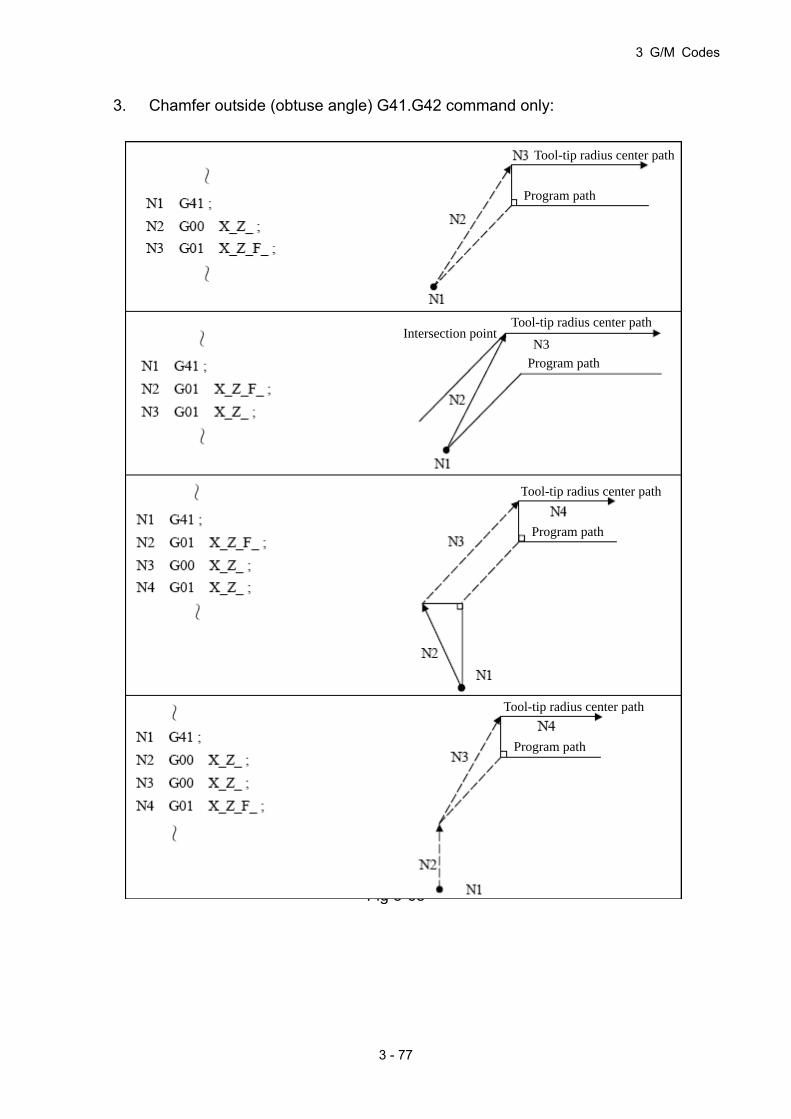
3 G/M Codes
3 - 77
3. Chamfer outside (obtuse angle) G41.G42 command only:
Fig 3-63
Tool-tip radius center path
Program path
Tool-tip radius center path
Tool-tip radius center path
Tool-tip radius center pathIntersection point
N3
Program path
Program path
Program path

HUST CNC H4D-T Manual
3 - 78
4. Chamfer outside (obtuse angle) G41.G42 exists in the same block with a
move command:
Fig 3-64
Program path
N2 Tool-tip radius center pathIntersection point
S

3 G/M Codes
3 - 79
5. Chamfer outside (acute angle) G41.G42 command only:
Fig 3-65
Type A Type B
Tool-tip radius center path
Program path
Tool-tip radius center path
Program path
Tool-tip radius center path
Program path
Tool-tip radius center path
Program path
Tool-tip radius center path
Program path
Tool-tip radius center path
Program path
Tool-tip radius center path
Program path
Tool-tip radius center path
Program path

HUST CNC H4D-T Manual
3 - 80
6. Chamfer outside (acute angle) G41.G42 exists in the same block with a
move command:
Fig 3-66
Type A
S
Type B
Tool-tip radius center path
Program path
Tool-tip radius center path
Program path

3 G/M Codes
3 - 81
Intersection point
Arc center
LineLine (acute angle)
ArcArc (obtuse angle)
LineArc (acute angle)
ArcLine (acute angle)
ArcArc (acute angle)
Tool-tip radius center path
Program path
Tool-tip radius center path
Program path
LineLine (obtuse angle)
LineArc (obtuse angle)
ArcLine (obtuse angle)
Program path
Tool-tip radius center path
Program path
Tool-tip radius center path
Program path Program path
Program path
Tool-tip radius center path
Tool-tip radius center path
Intersection point
Tool-tip radius center path
Tool-tip radius center path
Intersection point
Intersection point
Intersection point
Intersection point
Arc center
Arc center
Arc center Arc center
Arc center
Arc center
Arc center
Operation in a tool-tip compensation mode:
In the tool-tip radius compensation (G41,G42) mode, a tool-tip radius
compensation command having the same content is not valid. Pre-reading is
prohibited if a G65 L50 command is included in the tool-tip radius compensation.
1. Rotation of chamfer inside:
Fig 3-67

HUST CNC H4D-T Manual
3 - 82
2. Rotation of Chamfer outside: (Fig. 3-68)
交點
交點
Type A
Type A
Type B
Type B
Type A / B
Type A / B
Type A / B
Type A / B
Type A / B
Type A / B
LineLine LineLine
LineLine LineLine
LineArc LineArc
ArcLine ArcLine
ArcArc ArcArc
Intersection point
Tool-tip radius center path
Program path
Tool-tip radius center path
Program path
Program path
Tool-tip radius center path
Tool-tip radius center path
Program path
Program path
Tool-tip radiuscenter path
Program path Tool-tip radiuscenter path
Tool-tip radiuscenter path
Program path Program path
Tool-tip radius center path
Tool-tip radius center path
Program path Program path
Tool-tip radius center path
Arc center
Arc center
Arc center
Arc center
Arc center
Arc center
Arc center
Arc center
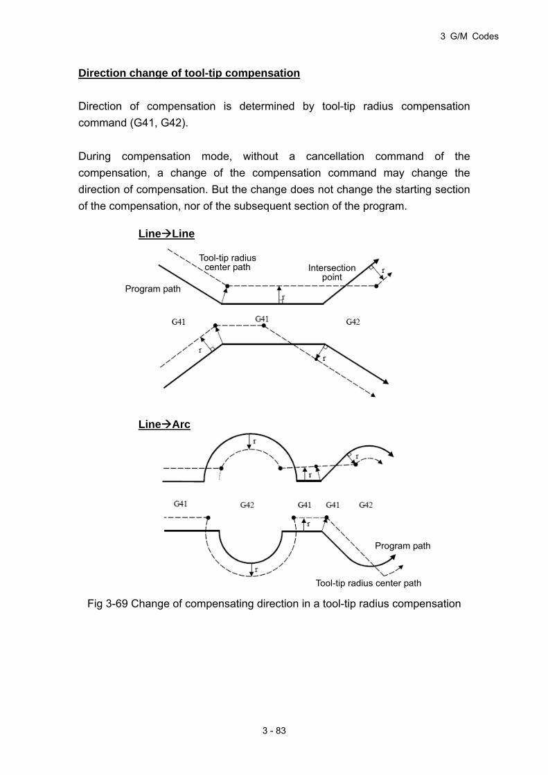
3 G/M Codes
3 - 83
Direction change of tool-tip compensation
Direction of compensation is determined by tool-tip radius compensation
command (G41, G42).
During compensation mode, without a cancellation command of the
compensation, a change of the compensation command may change the
direction of compensation. But the change does not change the starting section
of the compensation, nor of the subsequent section of the program.
Fig 3-69 Change of compensating direction in a tool-tip radius compensation
Intersectionpoint
LineLine
LineArc
Program path
Tool-tip radius center path
Program path
Tool-tip radius center path

HUST CNC H4D-T Manual
3 - 84
Disabling a tool-tip radius compensation:
When tool-tip radius compensation is enabled and all the following conditions
are met, the tool-tip radius compensation can be disabled:
1. A G40 command is executed.
2. Executing a move command excluding the arc commend.
After reading-in the disable command of compensation, the program switches
into (compensation) disabled mode which comprises the following 3 conditions:
1. A tool-tip radius compensation ends, G40 alone disables tool
compensation, and a G00 precedes G40, tool compensation is disabled in
the block of a G00 move command.
2. A tool-tip radius compensation ends, G40 alone disables tool
compensation, and a G01/G02/G03 precedes G40, tool stops at the center
of tool-tip radius vertically, tool compensation remains enabled until the first
move command after G40. If no move command follows G40, tool
compensation remains enabled on the encounter of an end command
M02/M30; the compensation is disabled when the program is re-started,
without an operation for disabling tool compensation.
3. A tool-tip radius compensation ends, if G40 command is in the same
command line with a move command, tool compensation is disabled in the
G40 command block.

3 G/M Codes
3 - 85
Program path
Tool-tip radius center path
Program path
Program path
Program path
Tool-tip radius center path
Tool-tip radius center path
Tool-tip radius center path
Disabling tool radius compensation:
1. Chamfer inside G40 command only:
Fig 3-70

HUST CNC H4D-T Manual
3 - 86
2. Chamfer inside G40 is in the same block as a move command:
Fig 3-71
LineLine ArcLine
R= Tool-tip radius
Arc centerEE
Program path
Tool-tip radius center path
Program path
Tool-tip radius center path

3 G/M Codes
3 - 87
3. Chamfer outside (obtuse angle) G40 command only:
Fig 3-72
Type A Type B
Tool-tip radius center path
Program path
Tool-tip radius center path
Program path
Tool-tip radius center path
Program path
Tool-tip radius center path
Program path
Tool-tip radius center path
Program path
Tool-tip radius center path
Program path
Tool-tip radius center path
Program path
Tool-tip radius center path
Program path

HUST CNC H4D-T Manual
3 - 88
4. Chamfer outside (obtuse angle) G40 and move command in the same
block:
Fig 3-73
Type A Type B
LineLine LineLine
ArcLine ArcLine
Arc center Arc center
E E
E E
Tool-tip radius center pathTool-tip radius center path
Tool-tip radiuscenter path
Tool-tip radiuscenter path
Program path
Program path
Program path

3 G/M Codes
3 - 89
5. Chamfer outside (acute angle) G40 command only:
Fig 3-74
Type A Type B
Tool-tip radius center path
Program path
Tool-tip radius center path
Program path
Tool-tip radius center path
Program path
Tool-tip radius center path
Program path
Tool-tip radius center path
Program path
Tool-tip radius center path
Program path
Tool-tip radius center path
Program path
Tool-tip radius center path
Program path

HUST CNC H4D-T Manual
3 - 90
6. Chamfer outside (acute angle) G40 and move command in the same block:
Fig 3-75
3.27.3 Interference Check
Functions and Purposes:
When pre-reading-in 2 program blocks to perform a tool-tip radius compensation,
it often results in cutting into the workpiece; this is called an interference.
When cutting a stepwise work-piece with a step value smaller than the tool
radius, an over-cutting alarm is generated as shown in Figure 3-51.
Fig. 3-76 Over-cutting (Shaded Area)
An interference check is a check against such conditions, for taking responding
actions according to the parameter.
Interference handling comprises the following 3 functions that can be selected
by parameter setting.
Arc center
E E
E E
Type A Type B
LineLine LineLine
ArcLine ArcLine
Tool-tip radius center path
Program path
Tool-tip radius center path
Program path
Tool-tip radius center path
Program path
Arc center Tool-tip radius center path
Program path

3 G/M Codes
3 - 91
Function Parameter Action
Interference check
alarm
Parameter 20=0 Issues alarm and stop machine
before entering block of interference.
Interference
avoidance function
Parameter 20=1 Alter the path automatically to avoid
interference.
Interference check
disable
Parameter 20=2 Cutting action continues, allowing
cutting into workpiece.
Details (Ex.)
Fig 3-77
1. Interference check alarm: An alarm occurs before executing N1, process
stops.
2. Interference avoidance function: N1 and N3 calculate intersection point, for
altering the path to avoid interference.
3. Interference check disabled: continue cutting into N1 and N3 lines.
Interference handling alarm
An interference alarm occurs when any of the following conditions take place:
1. Interference check alarm selected: In the event of interference, an alarm is
issued before the block of interference in the program.
Avoidance path
Tool diameter
Cutting with N2 Cutting with N2

HUST CNC H4D-T Manual
3 - 92
Issues alarm and stop
Issues alarm
and stop
2. Interference avoidance function selected:
a. Interference occurs in two consecutive blocks in the program.
(Interference in both N2 and N3).
Fig 3-78
b. An avoidance path cannot be found (no intersection of N2 and N4),
Fig 3-79

3 G/M Codes
3 - 93
c. Direction of program path is opposite the path after interference
avoidance (direction of path after interference avoidance is opposite to
N2 direction).
Fig 3-80
3.27.4 Notes on Tool Radius Compensation
1. When radius compensation is executed, there should be at least one block
containing positioning commands between two neighboring blocks. The
following commands do not perform tool positioning, though they have
mechanical actions. Therefore they are not allowed for continuous blocks .
M05 ....M-code output
S2100 ....S-code output
G4 X1.000 ....Suspension
G1 U0.000 ....Feed distance=0
G98 ....G-code only
2. Only G00 and G01 are applicable to blocks with tool-tip radius
compensation. Arc commands G02, G03 are not allowed
3. The move block before a tool-tip radius compensation command must be
G00 or G01. Arc commands G02, G03 are not allowed.
4. The tool radius compensation function is not available for MDI operation.
5. Tool-tip radius compensation is not allowed for G74, G75, or G76.
Dashed line:
The path before interference avoidance
Solid line:
The path after interference avoidance

HUST CNC H4D-T Manual
3 - 94
6. Pre-read preventive commands (G65, L50) are not allowed during the
tool-tip radius compensation mode.
Tool-tip Radius Compensation Example:
Tool number = 02, tool-tip direction = 3, tool-tip radius = 1.5 mm. The X-axis
coordinate is defined by the diameter.
Fig. 3-81
N10 G0 X100. Z120. ...Point S
N20 G0 X0. Z110. ...Point 1
N30 M3 S2000
N40 G42 Z100. T02 F3.0 ...Point 2, compensation
insertion
N50 G1 X20. ...Point 3
N60 X30. Z91.34 ...Point 4
N70 Z75. ...Point 5
N80 G02 X44.644 Z57.322 I25. F1.5 ...Point 6, arc cutting
N90 G01 X76. Z37.644 F3.0 ...Point 7
N100 Z20. ...Point 8
N110 X80. ...Point 9
N120 Z0. ...Point 10
N130 G40 X90. ...Point 11, compensation
cancellation
N140 G0 X100. Z120. ...Point S
N150 M05
N160 M02
11 10 9
8 7
6 5 4
3
2 1
R=25
S Start point
Z
X
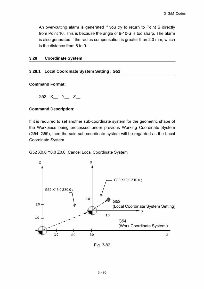
3 G/M Codes
3 - 95
G52 X15.0 Z30.0 ;
G00 X10.0 Z10.0 ;
G52 (Local Coordinate System Setting)
G54 (Work Coordinate System)
An over-cutting alarm is generated if you try to return to Point S directly
from Point 10. This is because the angle of 9-10-S is too sharp. The alarm
is also generated if the radius compensation is greater than 2.0 mm, which
is the distance from 8 to 9.
3.28 Coordinate System
3.28.1 Local Coordinate System Setting , G52
Command Format:
G52 X__ Y__ Z__
Command Description:
If it is required to set another sub-coordinate system for the geometric shape of
the Workpiece being processed under previous Working Coordinate System
(G54..G59), then the said sub-coordinate system will be regarded as the Local
Coordinate System.
G52 X0.0 Y0.0 Z0.0: Cancel Local Coordinate System
Fig. 3-82

HUST CNC H4D-T Manual
3 - 96
Example of the Program:
G54: Designate the Working Coordinate System as G54.
G52 X19.0 Z30.0: Designate Local Coordinate System to X15.0 Z30.0
position of the current working coordinate system.
G00 X10. Z10: Quickly move to X10.0 Z10.0 position of Local Coordinate
System.
G52 X0.0 Z0.0: Cancel the Local Coordinate System setting.
Remark:
1. The Resume Signal will override the Local Coordinate System.
2. When switching G54_ _G59 Working Coordinate System, the Local
Coordinate System will be cancelled.
3.28.2 Basic machine coordinate system , G53
Command Format
G53 X__ Y__ Z__ A__ B__ C__ P0
or G53 X__ Y__ Z__ A__ B__ C__
X:X-axis moves to the designated Machine Coordinate X position with G00
speed.
Y:Y-axis moves to the designated Machine Coordinate Y position with G00
speed.
Z:Z-axis moves to the designated Machine Coordinate Z position with G00
speed.
A:A-axis moves to the designated Machine Coordinate A position with G00
speed.
B:B-axis moves to the designated Machine Coordinate B position with G00
speed.
C:C-axis moves to the designated Machine Coordinate C position with G00
speed.
G53 X__ Y__ Z__ A__ B__ C__ P1
X:X-axis moves to the designated Machine Coordinate X position with G01
speed of previous node.

3 G/M Codes
3 - 97
Y:Y-axis moves to the designated Machine Coordinate Y position with G01
speed of previous node.
Z:Z-axis moves to the designated Machine Coordinate Z position with G01
speed of previous node.
A:A-axis moves to the designated Machine Coordinate A position with G01
speed of previous node.
B:B-axis moves to the designated Machine Coordinate B position with G01
speed of previous node.
C:C-axis moves to the designated Machine Coordinate C position with G01
speed of previous node.
Description
The Home Position of the machine is the fixed home position being set by the
manufacturer when manufacturing the CNC machine and such Coordinate
System belongs to a fixed system. When designated by G53 Command and
coordinate command, the Tool will move to the position designated for the basic
coordinate system of the machine. Soon as the Tool returns to zero point (0, 0, 0)
of the machine, it means the Home Position of the machine’s coordinate system.
Notice
1. G53 Command will be valid for the designate node.
2. Before giving the G53 Command, the Tool offsetting must be cancelled
(length, wearing, tip radius offsetting).
3. The command shall be valid under absolute value programming status, and
will not avail under incremental value programming.
3.28.3 Work Coordinate System, G54~G59
Purpose and functions:
Six sets of different work origins can be set. The coordinate system comprising
these work origins is named Work Coordinate System. The major merit of a
Work Coordinate System is the simplified calculation of coordinates in the
process program.
Details:

HUST CNC H4D-T Manual
3 - 98
The program use these work coordinate origins via commands G54-G59.
According to process requirements and program design, the user may select any
set, or 2 sets or even 6 sets for the process. The major merit of these Work
Coordinate Systems is the simplified calculation of coordinates in the process
program.
1. The following table describes the relationship between G54~G59 Work
Coordinate System and setting values of X, Y, Z, A, B, C items of MCM
parameters 1~120. These coordinate parameters (work origins)
correspond to machine coordinates by setting the machine origin as zero,
therefore the work origin settings of work coordinates G54~G59 are as
follows. An illustration is given taking X & Z 2 axes as the example:
Table 3-12
Work coordinate
system
Parameter Item/Number
X-axis setting value
Z-axis setting value
G54 1(X), 3(Z) -100.000 -70.000
G55 21(X), 23(Z) -30.000 -80.000
G56 41(X), 43(Z) -50.000 -80.000
G57 61(X), 63(Z) -50.000 -70.000
G58 81(X), 83(Z) -60.000 -40.000
G59 101(X), 103(Z) -40.000 -20.000
Fig. 3-83 G54~G59 Work Coordinate System
Mechanical
Origin
-10
-70
-60
-50
-40
-30
-20
-10 -20 -30 -40 -50 -60 -70 -80 -90
G59
G54
G55
G56 G57
G58
Z
X

3 G/M Codes
3 - 99
2. When a Work Coordinate System is selected, program coordinates also
change accordingly. The altered coordinates are based on the Work
Coordinate System. Adding circular and semi-circular cuttings in program
of the above figure, the application of G54 and G55 can be described by
the following example. (Fig.3-84)
Fig. 3-84 G54~G59 application
Program Example:
N1 G54 ... Select the first work coordinate
N2 G0 X0 Z0 ... Positioned to program coordinates X0, Z0,
(Machine coordinates X-10. Z-70.)
N3 G2 I-7.0 F200 ... Cut a full circle with R7.0 clockwise
N4 G0 ... Set feed mode as FAST
N5 G55 ... Select the second work coordinate
N2 G0 X0 Y0 ... Positioned to program coordinates X0, Z0,
(Machine coordinates X-30., Z-80.)
N6 G1 W10.0 F300 ... Z-axis cutting incremental feed command,
travel +10.0
N7 G3 W-20.0 R10.0 F300 ... Cut a R10.0 semi-circle counterclockwise
N8 G1 W10.0 F300. ... Z- axis cutting incremental feed command,
travel +10.0
N9 G28 ... If MCM parameter of first reference point =0,
Mechanical
Origin
-10
-70
-60
-50
-40
-30
-20
-10 -20 -30 -40 -50 -60 -70 -80 -90
G59
G54
G55
G56 G57
G58
R7
X
Y

HUST CNC H4D-T Manual
3 - 100
program returns to machine origin
N10 M2 ... Program end
1. Selection of Work Coordinate System is done by giving G54~G59
commands.
2. After giving G54~G59 commands, machine coordinates of the program
origin alter according to the new Work Coordinate System.
3. Controller automatically set as G54 Work Coordinate System when the
machine starts or when Reset is pressed.
3.29 Corner chamfer (,C_), round-angle chamfer (,R_) functions:
In a command block for forming a corner from a continuous line of any arbitrary
angle or from an arc, “,C_” or “,R_” can be used at the end of block to perform a
chamfer or a round-angle chamfer. They are applicable to both absolute and
incremental commands.
3.29.1 Chamfer ( , C__)
Functions and Purposes:
In 2 consecutive blocks, the “,C_” command in the first block executes a corner
chamfer, “,C_” stands for the length from the assumed starting point to the end
point of the chamfer.
Command Format:
N100 G0x X___ Z___ ,C___;
N200 G0x X___ Z___;
Where:
G0x : can be any of the G00, G01, G02, and G03 commands.
,C_ : is the length from the assumed starting point to the end point of the
chamfer.

3 G/M Codes
3 - 101
Hypothetical corner intersection point
Unit (mm)
Unit (mm)
Relative value command
Relative value command
Hypothetical corner intersection point
Program Example:
1. Line-Arc
Fig. 3-85
2. Arc-Arc
Fig. 3-86
Absolute value command
Absolute value command

HUST CNC H4D-T Manual
3 - 102
Relative value command
Hypothetical corner intersection point
Unit (mm)
3.29.2 Round-angle chamfer ( , R_ )
Functions and Purposes:
In 2 consecutive blocks, the “,R_” command in the first block executes a
round-angle chamfer. “,R_” stands for the radius of arc of the round-angle
chamfer.
Command Format:
N100 G0x X___ Z___,R___ ;
N200 G0x X___ Z___ ;
Where:
G0x:can be any of the G00, G01, G02, and G03 commands.
,R_ : is the radius of round-angle chamfer.
Program Example:
1. Line-Arc
Fig. 3-87
Absolute value command

3 G/M Codes
3 - 103
Relative value command
Absolute value command
Hypothetical corner intersection point
Unit (mm)
2. Arc-Arc
Fig. 3-88
3.30 Liner angle function ( ,A_)
Functions and Purposes:
Given a line angle and end coordinates of any axis, the end coordinates of
another axis can be calculated automatically.
Command Format:
G01 Z (X ),A_ ;
Fig. 3-89

HUST CNC H4D-T Manual
3 - 104
Program Example:
N01 G00 X50.0 Z50.0; Fast positioning to a specified point
N02 G01 Z100.0,A45.0; end point absolute Z-coordinate is100, tool path is
in a 45° phase difference with the level axis.
X-coordinate will be 100 after program execution.
Fig. 3-90
Details:
1. Angle indication:
Starting from the first axis (horizontal axis) of the selected plane, the
counterclockwise direction (CCW) is positive, counterclockwise direction
(CW) is negative.
2. Range of angle:
00.36000.360 , for an angle exceeding the 360.00 range, divide the
angle by 360.00 degrees and take the remainder. E.g., for an angle of
400.00 degrees, the remainder 40.00 after divided by 360.00 will be the
specified angle.
Other relevant functions:
Line angle+Chamfer/ Round-angle chamfer
EX1:
N1 G01 X___,A___,C___
N2 G03 X___ Z___ I___ J___

3 G/M Codes
3 - 105
Fig. 3-91
EX2:
N1 G01 X___,A___,R___
N2 G03 X___ Z___ I___ J___
Fig. 3-92
3.31 Geometry function command
Functions and Purposes:
If the intersection point of two line segments is hard to get, using inclination of
the first line and absolute coordinates of the end point of the second line and its
inclination, the end point of the first line can be determined automatically by the
internal system, with the move path controlled automatically.
Command Format:
G01,A___ ; Specifies inclination of the first line
G01 X___Z___,A___ ; Specifies the absolute coordinate of the end of
the next block and the inclination.

HUST CNC H4D-T Manual
3 - 106
Location E
Horizontal Axis
Fig. 3-93
Program Example:
N01 G00 X0.0 Z0.0 ;
N02 G01,A45.0;
N03 Z90.0 X0.0 ,A135.0;
Fig. 3-94
Details:
1. Angle indication: Starting from the first axis (horizontal axis) of the selected
plane, the counterclockwise direction (CCW) is positive, counterclockwise
direction (CW) is negative.
2. Range of angle: 00.36000.360 , for an angle exceeding the 360.00
range, divide the angle by 360.00 degrees and take the remainder. E.g., for
an angle of 400.00 degrees, the remainder 40.00 after divided by 360.00
will be the specified angle.
3. Report an error if relative coordinates are used for the end coordinates of
E (100,0)S (100,0)
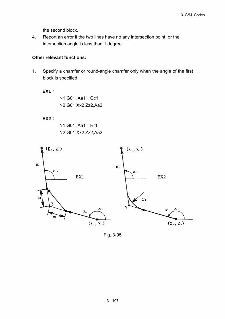
3 G/M Codes
3 - 107
the second block.
4. Report an error if the two lines have no any intersection point, or the
intersection angle is less than 1 degree.
Other relevant functions:
1. Specify a chamfer or round-angle chamfer only when the angle of the first
block is specified.
EX1:
N1 G01 ,Aa1,Cc1
N2 G01 Xx2 Zz2,Aa2
EX2:
N1 G01 ,Aa1,Rr1
N2 G01 Xx2 Zz2,Aa2
Fig. 3-95
EX1 EX2
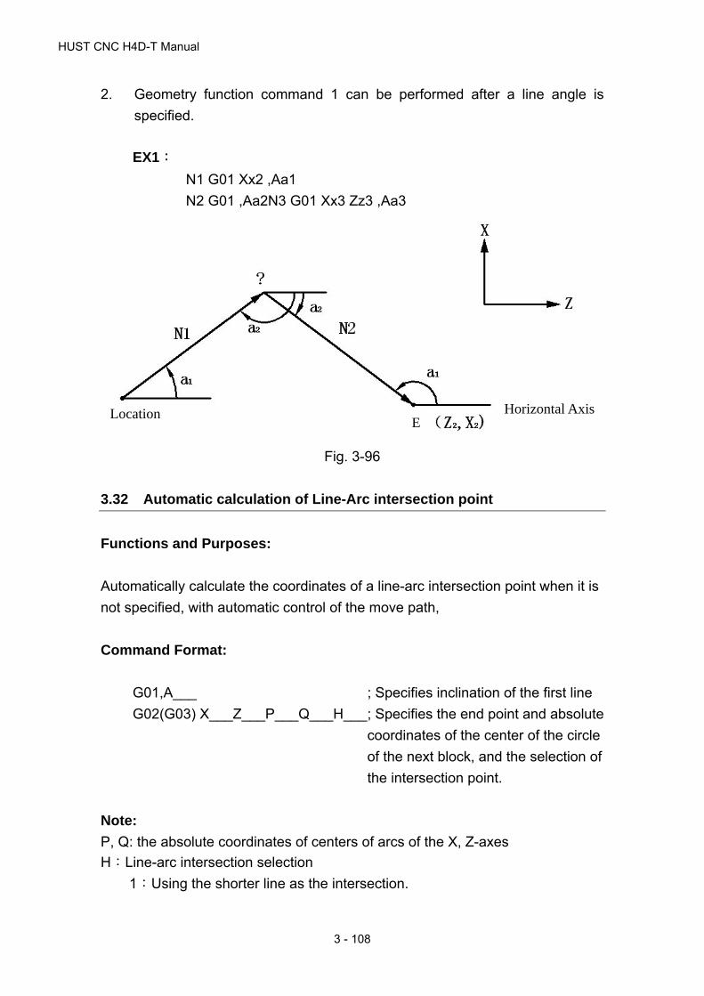
HUST CNC H4D-T Manual
3 - 108
2. Geometry function command 1 can be performed after a line angle is
specified.
EX1:
N1 G01 Xx2 ,Aa1
N2 G01 ,Aa2N3 G01 Xx3 Zz3 ,Aa3
Fig. 3-96
3.32 Automatic calculation of Line-Arc intersection point
Functions and Purposes:
Automatically calculate the coordinates of a line-arc intersection point when it is
not specified, with automatic control of the move path,
Command Format:
G01,A___ ; Specifies inclination of the first line
G02(G03) X___Z___P___Q___H___ ; Specifies the end point and absolute
coordinates of the center of the circle
of the next block, and the selection of
the intersection point.
Note:
P, Q: the absolute coordinates of centers of arcs of the X, Z-axes
H:Line-arc intersection selection
1:Using the shorter line as the intersection.
Location E
Horizontal Axis

3 G/M Codes
3 - 109
2:Using the longer line as the intersection. [???]
Fig. 3-97
N1 G01 ,Aa1 N1 G02(G03)Pp1 Qq1 H_
N2 G02(G03) Xx2 Zz2 Pp2 Qq2 H_ N2 G01 Xx2 Zz2 ,Aa3
Details:
1. Report an error when the second block is not absolute coordinates.
2. Report an error when the second block is an arc without P,Q specifications.
3. Report an error if the lines have no intersection point with the arc.
Relationship with other functions:
1. Finding line-arc intersection point + chamfer
EX1:
N1 G01,A___,C___
N2 G03 X___ Z___ P___ Q___ H___
Fig. 3-98
2. Finding line-arc intersection point + round-angle chamfer

HUST CNC H4D-T Manual
3 - 110
EX2:
N1 G01,A___,R___
N2 G03 X___ Z___ P___ Q___ H___
Fig. 3-99

4 MCM PARAMETERS
4 - 1
4 MCM Parameters
4.1 MCM Parameters
The MCM parameter setting function allows the user to define the controller
system constants according to mechanical specifications and machining
conditions.
These parameters are classified into two groups: basic parameters and MCM
parameters.
4.1.1 Basic Parameters
Quickly press the key twice to enter the parameter setting screen,as
shown below:
Fig 4-1
4.1.2 MCM Parameters
The correct and proper setting of these parameters is important for operation of
the mechanical system and fabrication of the work-piece. Make sure that the
setting is correct. Press to restart the machine when the MCM parameter
is successfully set
※ After pressing “F5-System Parameter” key in “User Parameter” page, the
System Parameter page can be accessed; but it can be reviewed and
cannot be revised, as per the figure below. To revise the system parameters,
press “F7-Revise Parameter” key and then input system parameter
I/O MCM
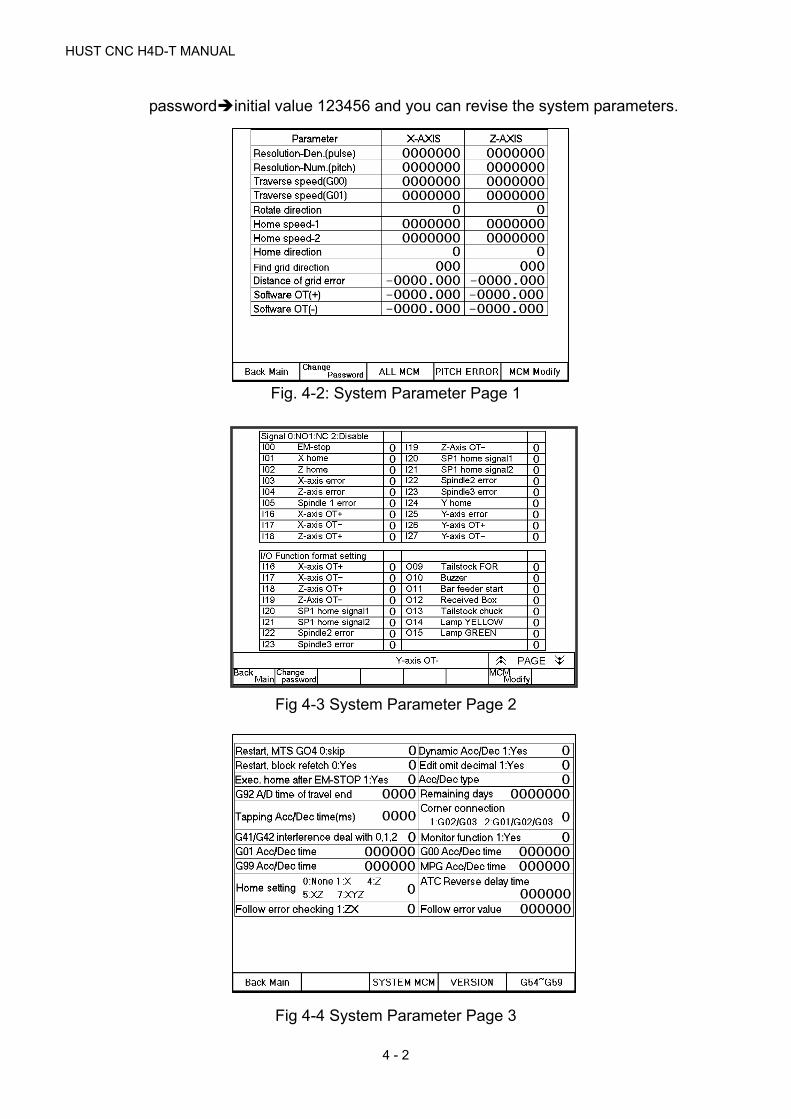
HUST CNC H4D-T MANUAL
4 - 2
passwordinitial value 123456 and you can revise the system parameters.
Fig. 4-2: System Parameter Page 1
Fig 4-3 System Parameter Page 2
Fig 4-4 System Parameter Page 3
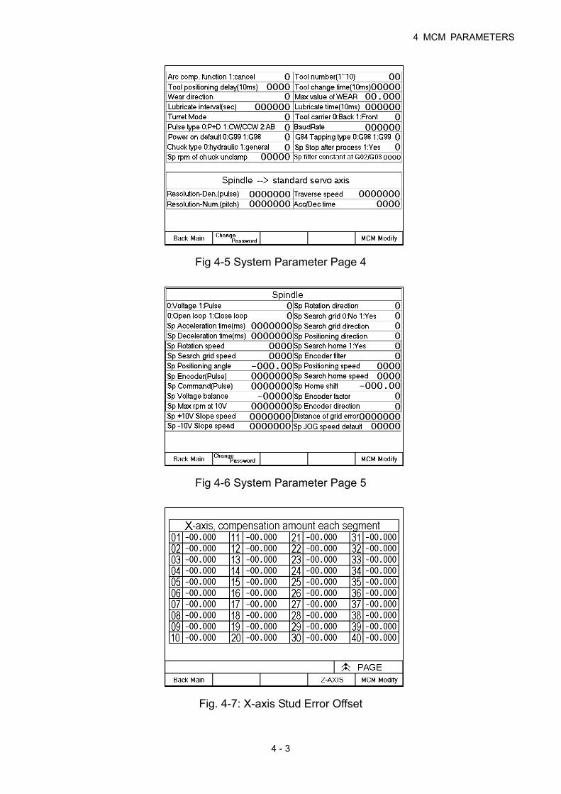
4 MCM PARAMETERS
4 - 3
Fig 4-5 System Parameter Page 4
Fig 4-6 System Parameter Page 5
Fig. 4-7: X-axis Stud Error Offset

HUST CNC H4D-T MANUAL
4 - 4
Fig 4-8 Z-axis Stud Error Offset
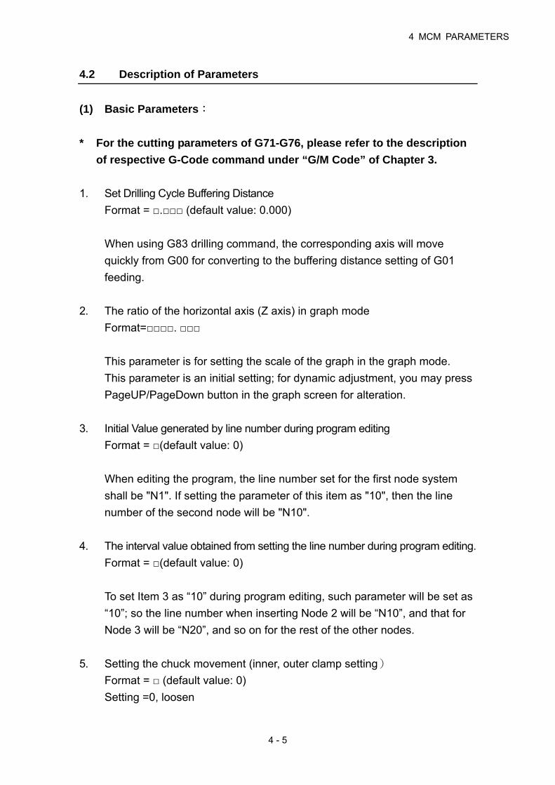
4 MCM PARAMETERS
4 - 5
4.2 Description of Parameters
(1) Basic Parameters:
* For the cutting parameters of G71-G76, please refer to the description
of respective G-Code command under “G/M Code” of Chapter 3.
1. Set Drilling Cycle Buffering Distance
Format = □.□□□ (default value: 0.000)
When using G83 drilling command, the corresponding axis will move
quickly from G00 for converting to the buffering distance setting of G01
feeding.
2. The ratio of the horizontal axis (Z axis) in graph mode
Format=□□□□. □□□
This parameter is for setting the scale of the graph in the graph mode.
This parameter is an initial setting; for dynamic adjustment, you may press
PageUP/PageDown button in the graph screen for alteration.
3. Initial Value generated by line number during program editing
Format = □(default value: 0)
When editing the program, the line number set for the first node system
shall be "N1". If setting the parameter of this item as "10", then the line
number of the second node will be "N10".
4. The interval value obtained from setting the line number during program editing.
Format = □(default value: 0)
To set Item 3 as “10” during program editing, such parameter will be set as
“10”; so the line number when inserting Node 2 will be “N10”, and that for
Node 3 will be “N20”, and so on for the rest of the other nodes.
5. Setting the chuck movement (inner, outer clamp setting)
Format = □ (default value: 0)
Setting =0, loosen

HUST CNC H4D-T MANUAL
4 - 6
Setting =1, tighten
This parameter is for specifying whether the chuck is loosened or tightened
in a protruding action.
6. Working Count Upper Limit Setting
Format = □□□□□□□ (default value: 0)
If the working count range is set as “0”, then it means the counting limit will
be ignored.
To execute the count, please add M15 in the working program (placed at
the end of each processed Workpiece).
If receiving M15 Command when running the program, the system will add
"1" to the number of the processed Workpieces automatically. Upon
reaching the upper limit set for the Workpiece, the System will change to
pausing status, reminding the customer that it has completed the set
working count.
After reaching the upper limit count, the count arriving status can be
cancelled by the following three methods:
a. In Auto page, click the “0” key twice and the worked count will be
cleared and set to zero.
b. Restart the program. You may also clear and set the worked count zero
in order to restart the counting.
c. Press the Reset key and the count arriving status can also be cancelled
and the worked count will be set to zero.
7. Time delay for chuck tightening
Format = □□□□ (default value: 50, unit:10ms)
If your key-in =50, the time delay is: 500 ms (50×10ms)
This parameter is set to ensure that the chuck is securely clamped on the
workpiece. In case the chuck fails to clamp the workpiece securely before
executing the subsequent block, the setting needs to be increased.
8. Remaining Service Days
Such parameter is provided for reading instead of writing.

4 MCM PARAMETERS
4 - 7
To remind the user to contact the machine manufacturing when the
remaining service days are going to arrive.
9. Whether or not wait for spindle to reach full speed before performing axial
feed
Format = □ (default value: 0)
Setting = 0, proceed the subsequent block without waiting for the full speed
of the spindle
Setting = 1, proceed with the subsequent block after the spindle reaches
full speed
For general cutting commands, axial feed can be performed without waiting
for the full spindle speed; for threading and drilling commands, to meet the
technical criteria, it may demand the spindle to reach a steady speed
before performing the cutting, therefore this parameter shall be set to 1, i.e.,
proceed with the subsequent block after the spindle reaches full speed
Setting this parameter to 1 affects the processing efficiency. Therefore the
user must consider and weigh the relationship between the technical
criteria and efficiency requirements for setting a proper value.
10. Radius or diameter programming
Format=□ (Default=0)
Setting= 0, X-axis is radius programming.
Setting= 1, X-axis is diameter programming.
Since general drawings indicate drills by its radius, setting this parameter to
0 may facilitate the programming process. The customer may alter this
parameter according to the actual requirements, so as to enable an easy
and direct way for programming.
11. Manual Tool Change Rotation Direction Setting:
Format = □ (default value: 0)
Setting = 0, it means CW.
Setting = 1, it means CCW.
The Turret service parameters can be based to set the rotating direction
when the Turret is operated under Manual Mode.

HUST CNC H4D-T MANUAL
4 - 8
Under Manual Mode, set this parameter to facility the site Tool change (e.g.
for T1→T8, set as “1”).
To check if the “I Point” required for Tool change is working normally when
performing the CW and CCW Tool change, you may set this parameter.
12. Omission of decimal point in programming
Format = □ (default value: 0)
Setting = 0, no omission of decimal point
Setting = 1, decimal point omitted.
See 2.2.2.3 decimal point principles for details
13. If the Tool lifespan management function is active
Format = □ (default value: 0)
Setting = 0, it means start.
Setting =1, it means close.
If the user sets stricter service life for all tools used, it is suggested that this
function should be activated in order to manage the tool and remind the
timing for Tool change. After activating such function, the program will stop
at T-Code when the Tool service time or the count is up.
14. Metric and imperial settings
Format = □ (default value: 0)
Setting = 0, metric system (unit: mm)
Setting = 1, imperial system (unit: inch)
Setting of the measurement unit (1inch = 25.4 mm). When Setting = 1, both
the coordinates and tool compensation are displayed to the 4th digit after
the decimal point.
15. Whether or not executing MTS G04 at a re-start
Format = □ (default value: 0)
Setting = 0, skip
Setting = 1, execute
This setting allows the user to select whether an MST code or a G04
command existing before the re-start block shall be executed or not when

4 MCM PARAMETERS
4 - 9
the program re-start function is enabled. The user may freely set this
parameter based on actual needs.
When the parameter is set to “0”, the MTS G04 command before the re-start
block will be omitted.
When the parameter is set to “1”, the MTS G04 command before the re-start
block will be executed normally.
16. Whether a re-start skips M98
Format = □ (default value: 0)
Setting = 0, do not skip
Setting = 1, skip
An M98 command (call sub-program) prior to the re-start block will be
carried out normally if this parameter is set to 0.
An M98 command (call sub-program) prior to the re-start block will not be
carried out if this parameter is set to 1.
17. Whether a re-start retrieves a prior block
Format = □ (default value: 0)
Setting = 0, retrieve
Setting = 1,no retrieve
Set to “0”" System retrieves a prior block when the re-start button is
pressed. Program goes to the block prior to the re-start block
and executes the prior block and the subsequent program.
Set to “1”" System starts execution from the re-start block without
retrieving the block prior to the re-start block.
18. Whether or not a smooth transit of tool-tip compensation is enabled
Format = □ (default value: 0)
Setting = 0, yes
Setting = 1, no
When G41, G42 function is enabled (see 3.24.2), setting this parameter to
1 will cause the tool-tip outside compensation to disable arc compensation
and take a line compensation.
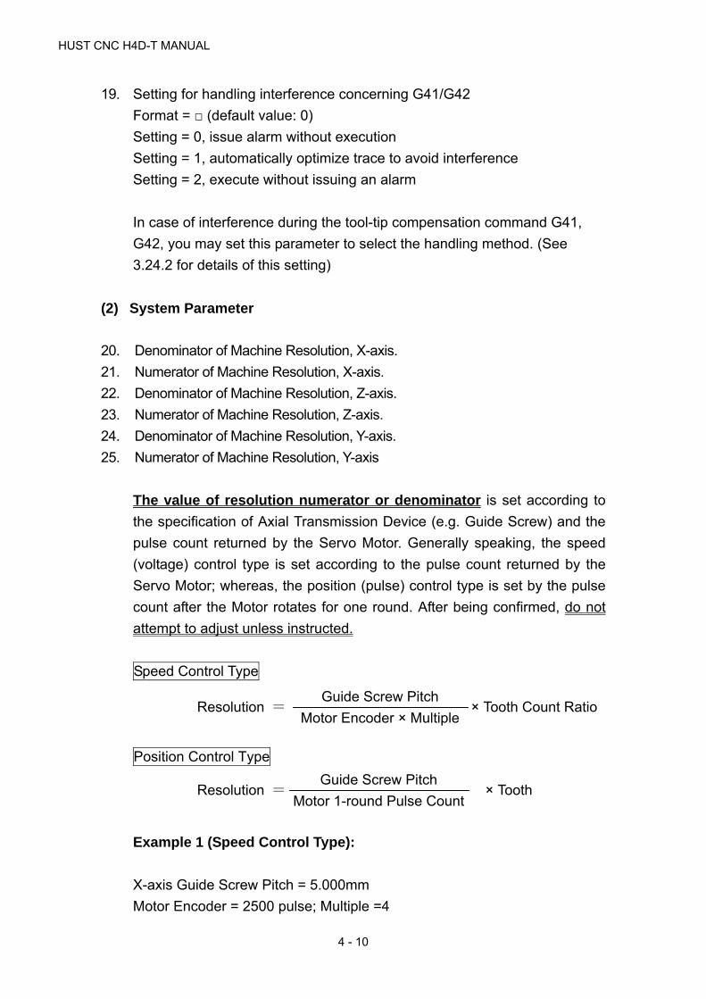
HUST CNC H4D-T MANUAL
4 - 10
19. Setting for handling interference concerning G41/G42
Format = □ (default value: 0)
Setting = 0, issue alarm without execution
Setting = 1, automatically optimize trace to avoid interference
Setting = 2, execute without issuing an alarm
In case of interference during the tool-tip compensation command G41,
G42, you may set this parameter to select the handling method. (See
3.24.2 for details of this setting)
(2) System Parameter
20. Denominator of Machine Resolution, X-axis.
21. Numerator of Machine Resolution, X-axis.
22. Denominator of Machine Resolution, Z-axis.
23. Numerator of Machine Resolution, Z-axis.
24. Denominator of Machine Resolution, Y-axis.
25. Numerator of Machine Resolution, Y-axis
The value of resolution numerator or denominator is set according to
the specification of Axial Transmission Device (e.g. Guide Screw) and the
pulse count returned by the Servo Motor. Generally speaking, the speed
(voltage) control type is set according to the pulse count returned by the
Servo Motor; whereas, the position (pulse) control type is set by the pulse
count after the Motor rotates for one round. After being confirmed, do not
attempt to adjust unless instructed.
Speed Control Type
Position Control Type
Example 1 (Speed Control Type):
X-axis Guide Screw Pitch = 5.000mm
Motor Encoder = 2500 pulse; Multiple =4
Resolution = × Tooth Count Ratio Guide Screw Pitch
Motor Encoder × Multiple
Resolution = × Tooth Guide Screw Pitch
Motor 1-round Pulse Count

4 MCM PARAMETERS
4 - 11
Tooth Count Ratio 5:1 (5 rounds for Servo Motor, 1 round for Guide Screw)
X-axis Resolution: Denominator Set Value = 10
X-axis Resolution: Numerator Set Value = 1
Example 2 (Position Control Type):
X-axis Guide Screw Pitch = 5.000mm
Motor 1-round Pulse = 10000 pulse
Tooth Count Ratio 5:1 (5 rounds for Servo Motor, 1 round for Guide Screw)
X-axis Resolution: Denominator Set Value = 10
X-axis Resolution: Numerator Set Value = 1
26. Set axis traverse speed limit
Format:□□□□□,Unit: mm/min (Default=10000)
Note : The format is only for integer.
The traverse speed limit can be calculated from the following equation:
Fmax = 0.95 * RPM * Pitch * GR
RPM : The ratio. rpm of Servo Motor motor
Pitch : The pitch of the ball-screw
GR : Gear ratio of ball-screw/motor
Ex: Max. rpm = 3000 rpm for X-axis, Pitch = 5 mm/rev, Gear Ratio = 5/1
Fmax = 0.95 * 3000 * 5 / 5 = 2850 mm/min
27. Direction of Motor Rotation, X-axis
28. Direction of Motor Rotation, Z-axis
Resolution = × 5000
10000
1
5
1
10=
Resolution = × 5000
2500×4
1
5
1
10=

HUST CNC H4D-T MANUAL
4 - 12
29. Direction of Motor Rotation, Y-axis
Format:□,(Default=0)
Setting = 0, Motor rotates in the positive direction. (CW)
Setting = 1, Motor rotates in the negative direction. (CCW)
This MCM can be used to reverse the direction of motor rotation if desired.
So you don’t have to worry about the direction of rotation when installing
motor. These parameters will affect the direction of HOME position
30. X-Homing speed-1
31. Z--Homing speed-1
32. Y-Homing speed-1
Format = □□□□ (default value: 2500, unit: mm/min)
In the homing process, the speed for an axial movement from the current
position to the position where the origin-switch is touched.
33. X-Homing speed-2
34. Z-Homing speed-2
35. Y-Homing speed-2
Format = □□□□ (default value: 40, unit: mm/min)
The speed the feedback device searches for Grid zero after the axial
position leaves the origin-switch in the homing process.
Items requiring the attention of the user; in the homing process, the
machine moves toward the origin-switch with the first-stage speed, the
length of the origin-switch must be longer than the deceleration
distance, otherwise the machine will exceed the proximity switch and this
results in a HOMING error.
The formula and an example for calculating the length of origin-switch are
as follows:
Length of origin switch (FDCOM × ACC) ÷60000
Note: FDCOM = First-stage speed of homing
ACC = Accelerate/ decelerate time of G01

4 MCM PARAMETERS
4 - 13
60000 msec ( 60s ×1000 = 60000 msec )
EX: FDCOM, First-stage speed of homing = 3000 mm/min
ACC, Accelerate/ decelerate time = 100 ms, then
Minimum length of origin-switch = (3000 × 100) ÷ 60000 = 5 mm.
36. X-Homing direction
37. Z-Homing direction
38. Y-Homing direction
Format = □ (default value: 0)
Setting = 0, Tool returns to machine origin along positive direction of
coordinate.
Setting = 1, Tool returns to machine origin along negative direction of
coordinate.
Set this parameter to adjust the homing direction if the user finds the
homing direction is not correct.
39. The direction that Servo Motor motor search the Grid when X-axis going
back to HOME.
40. The direction that Servo Motor motor search the Grid when Z-axis going
back to HOME.
41. The direction that Servo Motor motor search the Grid when Y-axis going
back to HOME.
Format = □□□ (default value: 0), Scope: 0, 1, 128, 256.
Taking X-axis for example:
Setting =0: Means when X-axis Motor returns to machine's Home
Position (HOME), the direction for Section-2 to leave Limit
Switch and for Section-3 to find zero point (GRID) will be
opposite to Section 1; whereas, the direction for Section-2
to leave Limit Switch and for Section-1 to find zero point
(GRID) will be the same, as per Fig. 4-11 (D)
Setting =1: Means when X-axis Motor returns to machine's Home
Position (HOME), the direction for Section-2 to leave the
Limit Switch will be consistent with that for Section-1;
whereas, the direction for Section-3 to find zero-point (GRID)
will be opposite to that for Section-1 and Section-2, as per
Fig. 4-11 (C).

HUST CNC H4D-T MANUAL
4 - 14
Setting =128: Means when X-axis Motor returns to machine's Home
Position (HOME), the direction for Section-2 to leave the
Limit Switch will be opposite to that for Section-1; in the
meantime, the direction for Section-3 to find GRID will also
be opposite that for Section-2 to leave the Limit Switch, as
per Fig. 4-11 (B).
Setting = 256: Means when X-axis Motor returns to machine's Home
Position (HOME), the directions for Section 1, Section-2 and
Section-3 will all be the same, as per Fig. 4-11 (A).
The speed for returning to HOME will be divided into the following 3 sections (as
per Fig. 4-11):
Section-1 Speed: Set in “HOME Return Speed 1” system parameter and the
direction will be set in “HOME Return Direction”.
Section-2 Speed: When the speed of Section 1 is reduced to “0”, the speed of
Section 2 will be set as 1/4 of that for Section 1; and its
direction will be determined according to the value contained in
the system parameter of “Encoder Find Zero Direction”.
Section-3 Speed: Used for finding the speed of zero-point (GRID) for Feedback
Device, which will be set by the System Parameter of “HOME
Return Speed 2”; its direction will be determined according to
the value contained in the system parameter of “Encoder Find
Zero Direction”.
The customer must notice that when returning to HOME, the machine will move
towards the Limit Switch with Section-1 speed and the length of said Limit
Switch must be longer than the deceleration distance; otherwise, the
machine will overshoot the Limit Switch and generate incorrect HOME-returning
phenomenon.
Listed below is the example explaining Limit Switch length calculation formula
and calculation method:
Limit Switch Length (FDCOM × ACC) ÷ 60000
Note: FDCOM = Section-1 speed for returning to HOME.
ACC = G01 acceleration/deceleration time

4 MCM PARAMETERS
4 - 15
60000 msec ( 60 sec ×1000 = 60000 msec )
Example: FDCOM HOME-returning Section-1 speed: 3000mm/min
ACC plus DECL time = 100ms, then,
Limit Switch min. length = (3000 × 100) ÷ 60000 = 5 mm
Fig. 4-11 (A): HOME Return Speed and Find Zero (GRID) Direction
Fig. 4-11 (B): Machine HOME Return Speed and Find Zero (GRID) Direction
Leave Limit Switch
Speed: HOME Return Speed 1 x 1/4
Encoder Find Zero Direction: 256 Touch Limit Switch
Find Encoder Zero-point
Speed: HOME Return Speed 2
Encoder Find Zero Direction: 256
Section-1: Home Return Speed 1
Section-2 Section-2
Tool Position
Speed
Section-3
Touch Limit SwitchSpeed
Section-1: HOME ReturnSection-3: Find Zero for Encoder
Speed: HOME Return Speed 2
Encoder Find Zero Direction: 128 Section-
Section-
2
Tool Position
Leave Limit Switch
Speed: HOME Return Speed 1 x 1/4
Encoder Find Zero Direction: 128

HUST CNC H4D-T MANUAL
4 - 16
Fig. 4-11 (C): Machine HOME Return Speed and Find Zero (GRID) Direction
Fig. 4-11 (D): Machine HOME Return Speed and Find Zero (GRID) Direction
42. X-axis Encoder Find Zero-Point Max. Distance
43. Z-axis Encoder Find Zero-Point Max. Distance
44. Y-axis Encoder Find Zero-Point Max. Distance
Format=□□□□□□□ (default value: 1000.000; Unit: mm)
Scope: 0~9999.999mm
Max. distance limit for Servo Motor to find the Grid signal.
Example: If the distance after X-axis Servo Motor turns for 3/4 round is
5.000mm, then Parameter 42 will be 5.200.
Note: If the Servo Motor fails to find out the Grid point after exceeding
the set scope, then the system will display “ERR 15” alarm message.
45. Software OT Limit in (+) Direction, X-axis.
Speed
Section-2Section-3Tool Position
Touch Limit Switch
Find Zero for Encoder Speed: HOME Return Speed 2Encoder Find Zero Direction: 0
Leave Limit Switch Speed: HOME Return Speed 1 x 1/4 Encoder Find Zero Direction: 0
Section-1: HOME
Return Speed
Speed Touch Limit SwitchSection-1: HOME
Return Speed Leave Limit Switch
Speed: HOME Return Speed 1 x 1/4
Encoder Find Zero Direction: 1 Section-2
Tool Position
Section-3 Find Zero for Encoder t
Speed: HOME Return Speed 2
Encoder Find Zero Direction: 1

4 MCM PARAMETERS
4 - 17
46. Software OT Limit in (+) Direction, Z-axis.
47. Software OT Limit in (+) Direction, Y-axis.
Format:□□□□□□□,Unit: mm/min (Default=9999.999)
Set the software over-travel (OT) limit in the positive (+) direction, the
setting value is equal to the distance from positive OT location to the
machine origin (HOME).
48. Software OT Limit in (-) Direction, X-axis.
49. Software OT Limit in (-) Direction, X-axis.
50. Software OT Limit in (-) Direction, X-axis.
Format:□□□□.□□□,Unit: mm/min (Default=-9999.999)
Set the software over-travel (OT) limit in the negative (-) direction, the
setting value is equal to the distance from negative OT location to the
machine origin (HOME).
Travel Limit Concept and Description:
Fig. 4-12
Note: The software travel limit setting point is approx. 5~10mm to
EM-TOP.
51. X-axis Denominator, MPG Hand-wheel Resolution Adjustment. (pulse)
EM-TOP
Actual Hardware
5~10mm each5~10mm each
EM-TOP
Machine Origin (Home)
Software OT Limit

HUST CNC H4D-T MANUAL
4 - 18
52. X-axis Numerator, MPG Hand-wheel Resolution Adjustment. (m)
53. Z-axis Denominator, MPG Hand-wheel Resolution Adjustment. (pulse)
54. Z-axis Numerator, MPG Hand-wheel Resolution Adjustment. (m)
55. Y-axis Denominator, MPG Hand-wheel Resolution Adjustment. (pulse)
56. Y-axis Numerator, MPG Hand-wheel Resolution Adjustment. (m)
Format:□□□□,(Default = 100)
Example: If Item 51 Parameter = 100; Item 52 Parameter = 100; and Hand
Wheel Multiple is 100%, then,
Hand Wheel moving for 1 frame = 100 Pulse
and X-axis Feed Distance = 100x (100÷100)=0.1mm
57. Max. value of U, W tool compensation can be entered during the operation
Format = □.□□□ (default value: 2.000, Max. value is 2.000, unit: mm)
Alteration of tool compensation data during the operation can only be made
with incremental method. This parameter is used to set a maximum value
for preventing tool collision.
Setting value =0.000, denotes no alteration of tool compensation data
during the operation.
58. Pitch Error Compensation Mode Setting, X-axis.
59. Pitch Error Compensation Mode Setting, Z-axis.
60. Pitch Error Compensation Mode Setting, Y-axis.
Format:□ , Default=0
Setting = 0, Compensation canceled.
Setting = -1, Negative side of compensation.
Setting = 1, Positive side of compensation.
Note: The screw offsetting will be allowed only one direction at a time.
X-axis Y-axis Z-axis Explanation
0 0 0 Compensation cancel
-1 -1 -1 Do compensation when tool is on the (-) side of the reference point
1 1 1 Do compensation when tool is on the (+) side of the reference point.
61. Segment Length for Pitch Error Compensation, X-axis

4 MCM PARAMETERS
4 - 19
62. Segment Length for Pitch Error Compensation, Z-axis
63. Segment Length for Pitch Error Compensation, Y-axis
Format=□□□□.□□□, Default=0, Unit=mm
Note: The offset value of each section will be entered by pressing
“Screw Offset” soft key, and at most 40 sections will be allowed
(as per Fig. 4-8, 4-9, 4-10).
The length setting scope of each section for offsetting the error of
screw pitch will be 20~480mm.
When the setting of offset length is below 20mm, then the length
shall be set at 20mm.
The offset setting means the incremental value, which cab
expressed either in positive or negative manner. If the offset
section count is less than 40 sections, then the parameter of the
remaining sections must be set at zero (0).
Example: Assuming the total length of the X-axis screw is 1m (1000mm),
and where it will be divided into 10 sections for offsetting:
Fig. 4-13
Therefore, the average length of each section is 100mm. It means that the
set value of “X-axis Screw Pitch Error Offset per Distance Section” is X =
100.000; in which, the offset of each section is set by parameter items (as
per Fig. 4-8, Section 01~10) and Section 11~40 must be set as zero.
64. Spindle type (Re-start enabled)
Format = □ (default value: 0)
Setting = 0, Voltage type spindle
Setting = 1, Pulse type spindle
User may make corresponding settings according to the actual control of
spindle.
65. Set Loop Open/Close Control Method (Restart avail)
Format = □ (default value: 0)
1000 mm
100mm
HUST CNC H4D-T MANUAL
4 - 20
Setting = 0: Spindle open loop control.
Setting =1: Spindle closed loop control (Spindle alignment control).
For the Spindle of Inverter, such parameter shall be set as “0”.
For the Spindle of Voltage-type Servo Motor, such parameter can be set
according to the wiring method (see 5-15, 5-16).
For the Spindle of Pulse-type Servo Motor, such parameter would be
meaningless.
66. Set Spindle Acceleration/Deceleration Time
Format=□□□□ (default value: 100, using “ms” as the unit).
Setting Scope: 2~3000 ms.
Such parameter must be set according to actual characteristics of the
machine, and it can be observed through manual Spindle starting and
stopping. The said parameter shall be measured to see if it is appropriately
set according to the indicators such as if the Spindle is smooth during
starting and if it can stop stably during the stopping process.
Note: Described below is the setting of acceleration/deceleration time,
which must be executed according to the actual characteristics of
the machine. After modifying the parameter, it is also necessary to
observe if the operating mechanism is working stably and smoothly
during the starting and stopping process. As for the Spindle of the
Inverter, because the Spindle acceleration/deceleration time is
adjusted by the Inverter, so it is needed to set such parameter at the
minimum value, i.e. 2.
67. Setting of spindle speed at 10V voltage
Format = □□□□ (default value: 3000, unit: RPM)
For a variable-speed spindle, this parameter is used to adjust the linear
relationship between the spindle rpm and the voltage.
68. Setting of rotation direction of spindle
Format = □ (default value: 0)
Setting = 0, for positive rotation
Setting = 1, for negative rotation
4 MCM PARAMETERS
4 - 21
69. Set Manual Spindle Speed
Format=□□□□ (default value: 10, using “RPM” as the unit).
Such parameter can be used to set the Spindle jogging speed under
Manual Mode.
70. Setting of searching for GRID point
Format = □ (default value: 0)
Setting = 0, search for GRID point (encoder signal in Z-phase)
Setting = 1, no search for GRID point (encoder signal in Z-phase)
For a voltage type open-circuit spindle, the motor needs not to search for
the GRID point (encoder signal in Z-phase); for pulse type spindle and
voltage type closed-circuit spindle, this parameter can be set according to
actual needs.
71. Setting of rotation direction of spindle for search of GRID point
Format = □ (default value: 0)
Setting = 0, Positive rotating direction
Setting = 1, Negative rotating direction
Use this parameter to set the rotation direction of motor for search of GRID
point (encoder signal in Z-phase).
72. Setting of spindle rpm for search of GRID point
Format = □□□□ (default value: 1), unit: RPM
Use this parameter to set rotation speed of motor for search of GRID point
(encoder signal in Z-phase)
73. Setting of spindle orientation
Format = □ (default value: 0)
Setting = 0, Positive rotating direction for spindle orientation
Setting = 1, Negative rotating direction for spindle orientation
Use this parameter to set the rotating direction for spindle orientation in
manual mode.
74. Setting of rotation speed of spindle orientation

HUST CNC H4D-T MANUAL
4 - 22
Format = □□□□ (default value: 1), Unit: RPM
Use this parameter to set rotation speed for spindle orientation in manual
mode.
75. Set if to find the Spindle HOME signal
Format=□(default value: 0).
Setting = 0: Quit finding Spindle HOME Switch signal
Setting = 1: Find Spindle HOME Switch signal
When setting the parameter as “1”, it means the finding of External HOME
Switch signal of the Spindle is required. In this case, please install the
External HOME Switch.
76. Set to find the speed of Spindle HOME signal
Format=□□□□ (default value: 0, using “RPM/Min” as the unit).
Set the RPM of Spindle when finding the external HOME Switch.
77. Setting of spindle origin offset
Format = □□□.□□ (default value: 0)
Set value of deviation of spindle origin
In case the position of machine origin when the spindle is assembled
deviates from the ideal position to the customer, this parameter may be
used for adjustment.
78. Setting of number of spindle feedback pulses
Format = □□□□□□□ (default value: 4096)
Sets number of feedback pulses per revolution of spindle based on the
number of spindle encoding lines.
79. Setting of number of pulses in the spindle command
Format = □□□□□□□ (default value: 4096)
Sets number of pulses to be generated by controller when spindle turns one
revolution.

4 MCM PARAMETERS
4 - 23
EX1: For a servo spindle with a gear mechanism having a gear ratio of 3:4, i.e.,
spindle rotates 4 turns when motor rotates 3 turns, the servo spindle
rotates 1 turn when receiving a pulse command of 10000.
In the above example, spindle rotates 1 turn when the spindle motor rotates
0.75 turns, meaning that the controller only needs to send out 7500 pulses
for the spindle to rotate 1 turn. Therefore, the parameter shall be set to
7500 instead of 10000. Since the servo spindle encoder is installed at the
electric machinery end, therefore the number of pulses in the spindle
feedback shall also be set to 7500. For the above conditions, suppose the
encoder is installed at the spindle end instead of the electric machine end,
and the encoder is of 1024 lines, then the number of pulses in the spindle
feedback shall be set to 4096 (=4*1024).
80. Setting of number of tools
Format = □□ (default value: 0)
Used in combination with powered turret, maximum 10 tools.
81. Set up the Turret type by the actual condition of the machine
Format =□ (default value: 0).
Setting = 0: Tool Row
Setting = 1: Electrical Turret
Setting = 2: Hydraulic Turret
Setting = 3: Electrical Turret 2
82. Setting of Tool positioning delay
Format = □□□□ (default value: 10, unit: 10 ms)
Default setting is 10, i.e., 100 ms.
In the event of miss-positioned tool change, properly increase this
parameter setting and observe if the tool change is better positioned.
83. Tool Change monitoring time setting
Format=□□□□ (default value: 200, using “10ms” as the unit).
Such parameter is used to monitor the time consumed during the entire
Tool change process. If the actual Tool change time exceeds the set value
of such parameter, then the screen will indicate “Tool Change Overdue”

HUST CNC H4D-T MANUAL
4 - 24
alarm signal. To remove the alarm, please refer to the function alarm
described in Chapter 6.
84. Setting of wear direction
Format = □ (default value: 1, positive)
Setting = 0, negative direction
Setting = 1, positive direction
User may make adjustment according the used direction for making
compensation for the wear.
85. Setting of maximum value of tool compensation
Format = □.□□□ (default value: 2.000; maximum value is 20.000, unit: mm)
This setting is used for setting an upper limit for the tool compensation
when the program is not in execution. In case exceeding the upper limit, an
alarm “protection limit exceeded” will be issued.
86. Setting of lubrication interval
Format = □□□□□□ (default value: 1800, unit:1s)
87. Setting of lubrication duration
Format = □□□□□□ (default value: 1000, unit:10ms)
88. Set the maximum rpm at which the chuck can be moved
Format = □□□ (default value: 100, unit: rpm)
Range: (0~500rpm)
EX:
A subsequent block to an M05 (Spindle Stop) command is M10 (chuck
loosen) command in the program; if this parameter is set as “100”, the
chuck can be loosened when the spindle decelerates to 100rpm; if the
parameter is set as “0”, the chuck can only be loosened until the spindle
comes to a full stop.
For a lathe furnished with an automatic material dispenser, adjusting this
parameter may increase the process efficiency.
89. Whether or not to enable the screen saver

4 MCM PARAMETERS
4 - 25
Format = □ (default value: 0)
Setting = 0, enable
Setting = 1, disable
When screen saver is enabled, the screen automatically enters sleep mode
when the controller remains untouched for 10 minutes, for prolonging
lifespan of the screen. Pressing any key will resume the display.
90. Set the type of Chuck Disc according to the actual conditions of the machine
Format = □ (default value: 0)
Setting = 0: Hydraulic Chuck Disc
Setting = 1: Ordinary Chuck Disc
91. If to startY-axis
Format = □ (default value: 0)
Setting = 0: No start
Setting = 1: Start
92. If to start Multi-function Hand Wheel
Format = □ (default value: 0)
Setting = 0: No start
Setting = 1: Start
When setting as “1” for starting the Multi-function Hand Wheel, the
adjustment of Hand Wheel multiple and the selection of axis will be
determined by pressing the Multi-function Hand Wheel multiple selection
and axis selection key.
93. Retention
94. Setting of Default feed mode at start-up
Format = □ (default value: 0)
Setting = 0, feed per revolution (G99).
Setting = 1, feed per minute (G98).
If G98 is the default mode, decimal point is not allowed in the F value. If F
value is set for pitch, add 3 “0” to the end, (Input of F500 indicating the pitch
value is 0.5 mm).
If G99 is the default mode, decimal point is allowed behind F.

HUST CNC H4D-T MANUAL
4 - 26
95. Setting of tool support type
Format = □ (default value: 0)
Setting = 0, rear support
Setting = 1, front support
User may set according to actual tool position. See description of pair-tools
for details about front and rear tool supports.
96. Setting of type of pulse type
Format = □ (default value: 0)
Setting = 0, pulse + direction
Setting = 1, positive/negative pulse
Setting = 2, A/B phase
Setting of this parameter requires setting of servo parameters, for matching
with pulse type generated by the pulse generator.
Suggest that the user shall set this parameter to “2, A/B phase”
97. Setting of acceleration/deceleration type
Format = □ (default value: 1)
Setting = 0, logarithm type
Setting = 1, linear type
Setting = 2, S-curve type
If no special requirement is raised for acceleration/deceleration, it is
suggested to set this parameter to “1”.
98. Setting of G01 acceleration/deceleration time constant
Format = □□□□□□ (default value: 100, unit: milli-second (ms))
Setting range: 2~3000 ms.
99. Setting of G00 acceleration/deceleration time constant
Format = □□□□□□ (default value: 100, unit: milli-second (ms))
Setting range: 2~3000 ms
100. Setting of G99 acceleration/deceleration time constant
Format = □□□□□□ (default value: 100, unit: ms)

4 MCM PARAMETERS
4 - 27
Setting range: 2~3000 ms, suggest to set both G00 and G99 to 100.
101. Setting of MPG acceleration/deceleration time
Format = □□□□□□ (default value: 64, unit: ms)
Setting range: 2~3000 ms.
Setting of motor acceleration/deceleration time in handwheel mode,
suggested setting value is 150.
102. Retention
103. Setting of spindle voltage zero correction value
Format = □□.□□□ (default value: 0, unit: mv)
Range: -99.999~+99.999
Adjusts spindle voltage zero (effective in open-circuit).
If system output is about --0.1V at system speed S0, then voltage zero
parameter (X) is: 20 (0.1V = X * 10V/2048). Adjust output voltage to be as
close to 0V as possible at system speed S0. This parameter is normally set
to 21.
EX: For adjusting spindle speed by inverter
a. First adjust this parameter so that output voltage is closest to 0V
when the rpm is zero.
b. Adjust the system parameter “Spindle RPM at 10V” in the controller
end screen to a rational value, so that the linear alteration of
spindle speed meets the site requirements.
The above operation is for providing the user with a general method. For
the substantial inverter, the user may use these parameters freely to adjust
the speed.
104. Setting of handwheel direction
Format = □ (default value: 0)
Setting = 0, X+, Z+.
Setting = 1, X-, Z+.
Setting = 4, X+, Z-.
Setting = 5, X-, Z-.

HUST CNC H4D-T MANUAL
4 - 28
If the handwheel has a wrong direction after connecting the wires, use may
alter the direction by setting this parameter.
105. Set Spindle Count
Format = □ (default value: 1; Max. value: 3)
Spindle 1 C-AXIS Connector
Spindle 2 A-AXIS Connector
Spindle 3 B-AXIS Connector
106. If to insert space in the displayed Node
Format = □ (default value: 0)
Setting = 0: Yes
Setting = 1: No
Example: In the editing program under N10 line number, the Spindle
performs CW rotation at 1000 RPM per minute. If setting this parameter as
“0”, then “N10 M03 S1000” will be displayed, with space between the line
number and the respective command code:
If setting as “1”, then “N10M03S1000” will be displayed, without space
between the line number and the respective command code:
107. Axis setting for returning to HOME
Format = □ (default value: 0)
Bit0-------X-Axis – 0: No HOME return; 1: HOME return
Bit1-------Y-Axis – 0: No HOME return; 1: HOME return
Bit2-------Z-Axis – 0: No HOME return; 1: HOME return
For example:
Setting = 0: Every axis will not return to HOME.
Setting = 1: X-Axis is returning to HOME.
Setting = 4: Z-Axis is returning to HOME.
Setting = 5: X/Z-Axis is returning to HOME.
108. Retention
109. Sensitivity of spindle RPM sensor
Format = □□□□ (default value: 1)

4 MCM PARAMETERS
4 - 29
The spindle feedback filter is constant when executing an arc cutting in the
G99 mode
For a setting =0, filter is not active. System performs a re-calculation
immediately as long as a change occurs in the number of spindle feedback
pulses.
For a setting =n, system performs a re-calculation only when the number of
feedback pulses exceeds n.
110. Setting for enabling detection against error follow
Format = □ (default value: 0)
Setting = 0, disable
Setting = 1, enable
For pulse type motors, this function shall be enabled to detect servo motor
follow error; however the error limit shall be set according to machine
conditions. Enabling this function can effectively protect the machine
against over-travel resulting from a servo error.
111. Setting of follow error
Format = □□□□□□□ (default value: 4095)
A Follow Error is defined as the difference between the position of the
controller command and the position of the actual servomotor feedback.
Servo follow error > setting value, an ERROR 02 alarm will be issued.
112. SIO Filtration Parameter Setting
Format = □□□□ (default value: 8, using “ms” as the unit)
Example: If setting this parameter as “8”, then the “I-Point” signal with
continuous time less than 8ms will not respond. Such parameter is
mainly used to resist the noise interference.
For the Electrical Turret or Hydraulic Turret, it is preferably to set the
parameter as “2” in order to assure that the system can quickly respond to
the IO signal of the Turret.
113. Enabling special acceleration/deceleration form

HUST CNC H4D-T MANUAL
4 - 30
Format = □ (default value: 0)
Setting = 0, disable
Setting = 1, enable
Enabling the special acceleration/deceleration form allows further
enhancement in the acceleration/deceleration efficiency based on the linear
type, s-curve type and exponential type acceleration/deceleration curves,
therefore elevating the execution efficiency.
In case the user finds that the efficiency of the machine is not enough during
the process, he may reach his aim by disabling parameters such as “wait for
spindle to reach full speed before performing axial feed” and “Enabling
special acceleration/deceleration form”.
114. Turning Corner Round Angle Connection
Format = □□□ (default value: 0)
0 = Set the Servo Motor acceleration/deceleration type to CNC standard
mode.
256 = Set the round angle connection between each Node.
115. Electrical Magazine CCW Delay (10ms)
Format = □□□□ (default value: 100, using “10ms” as the unit)
It is used to set the time delay required for locking the CCW action of the
Electrical Magazine.
116. Spindle 1 Chuck 1-Way/2-Way Solenoid Valve
Format = □ (default value: 0)
0 = 1-Way Solenoid Valve
In this case, the Spindle Chuck action is controlled by O09 independently.
I = 2-way Solenoid Valve
In this case, the Spindle Chuck action is jointly controlled by O09 and O05.
117. Hand Wheel Test Feed Rate Numerator
118. Hand Wheel Test Feed Rate Denominator
Format = □□□□□□ (default value: 100)
It is used to adjust the fast/slow program feed rate when testing the Hand
Wheel.
* Parameter for switching the Spindle back to standard axis

4 MCM PARAMETERS
4 - 31
119. Set the Rotation Direction
Format = □ (default value: 0)
Setting = 0: Forward direction
Setting = 1: Reverse direction
120. Set the Acceleration/Deceleration Time
Format = □□□□ (default value: 100, using “ms” as the unit)
Setting Scope: 4~3000 ms
121. Maximum feed speed
Format = □□□□□ (default value: 10000, unit: mm/min)
Note: Setting value shall be an integer (without a decimal point).
E.g.: Setting = 5000, indicates a maximum Z-axis feed rate of 5000mm per
minute.
Limit of max. feed speed is calculated as follows:
Fmax = 0.95 × Axial servomotor max. speed × axial pitch ÷ gear ratio
EX: X-axis servomotor max. speed is 3000 rpm, guide screw is 5 mm,
gear ratio is 5:1 (servomotor turns 5 revolutions, guide screw turns
1 revolution)
Fmax = 0.95×3000×5÷5 = 2850. Recommended setting is 2850.
122. Set Spindle Encoder Multiple
Format = □ (default value: 4)
Setting =1: Means feedback signal multiplied by 1.
Setting =2: Means feedback signal multiplied by 2.
Setting =4: Means feedback signal multiplied by 4.
Only one of the said three values can be selected.
123. Spindle feedback direction
Format = □ (default value: 0)
Setting = 0, feedback in positive direction
Setting = 1, feedback in negative direction

HUST CNC H4D-T MANUAL
4 - 32
In case the spindle speed indication displays normal but spindle position
displays abnormal, try to alter this parameter from “0” to “1”, see if the
position becomes accurate.
124. Set Resolution Denominator
Format = □□□□□□□ (default value: 4096)
125. Set Resolution Numerator
Format = □□□□□□□ (default value: 360000)
Example
Assuming C-axis is the rotating axis and the angle when rotating for one
round is 360.00 degrees.
Motor Encoder = 1024 Pulse in multiple =4, and the Spindle feedback pulse
count must be set as “4096”.
Tooth Count Ratio: 5:1 (Every 5 rounds of Servo Motor rotation will drive
C-axis to rotate for 1 round).
C-axis Resolution Denominator Set Value = 4096
C-axis Resolution Numerator Set Value = 36000
126. Spindle Feedback Filtration Frequency Setting
Format = □ (default value: 0)
Setting = 0: Filtration frequency is 500 KHz.
Setting = 1: Filtration frequency is 750 KHz.
Setting = 2: Filtration frequency is 1000 KHz.
Setting = 3: Filtration frequency is 342 KHz.
When setting the corresponding feedback filtration frequency according to
the Spindle Encoder setting, the System will be able to prevent the noise
interference effectively.
Example: If setting the parameter as “3” and Spindle Encoder as “1024”
with 4 times multiple, then the Spindle can reach 5000 RPM of maximum
speed. Note: 342K=4*1024*5000 (RPM)/60 sec
Resolution = × 1
5
36000
1024 × 4
36000
4096
=

4 MCM PARAMETERS
4 - 33
If setting Spindle Encoder as “2500” and requiring the Spindle to reach
3000 RPM of maximum speed, then such parameter must be set as “0”, i.e.
500 KHz. In this case, 500 KHz = 1*2500*3000/60.
The customer can set such parameter at moderate value according to the
Spindle Encoder installed for the machine and the required maximum
Spindle speed.
127. Retention.
128. Set G01 Tooth Gap Offset
Format = □.□□□ (default value: 0, using “mm” as the unit)
Scope: -9.999 ~ 9.999 mm, which can be used to remove the reverse gap
of the stud.
When performing reverse action, certain gaps may exist in the stud. In this
case, such parameter can be used to make correction.
129. Axis Feedback Direction Setting
Format = □(default value: 0)
Setting = 0, means the forward feedback direction.
Setting = 1, means the reverse feedback direction.
It is mainly used to set the feedback direction of X/Y/Z axes in order to save
the trouble of line change.
Note: If the axis rotation direction is set at “1”, it is necessary to change
such parameter as “1” to avid confusing the feedback signal.
130. Feedback Filtration Frequency Setting
Format = □(default value: 0)
Setting = 0, means the Filtration Frequency is 500 KHz
Setting = 1, means the Filtration Frequency is 750 KHz
Setting = 2, means the Filtration Frequency is 1000 KHz
Setting = 3, means the Filtration Frequency is 342 KHz
When setting the appropriate feedback filtration frequency according to
X/Y/Z axis Encoder, the System will be able to prevent the noise
interference effectively. For detailed content, please refer to the parameter
description under Item 123.
HUST CNC H4D-T MANUAL
4 - 34
131. Setting of pulse-width command (2.5 M/n or 2500 K/n)
Format = □ (default value: 5)
EX: Setting = 5, speed of pulse command is 500KPPS (2500K/5)
Setting = 4, speed of pulse command is 625KPPS (2500K/4)
132. Axis Manual Speed (mm/min)
Format =□□□□□□□ (default value:1000 mm/min)
The parameter is used to set the speed for driving the axis when operated
under Manual Mode.
133. 130 X-axis find Grid Front Deviation Length
134. 131 Z-axis find Grid Front Deviation Length
135. 132 Y-axis find Grid Front Deviation Length
Format = □□□□□□□ (default value: 0, using “mm” as the unit)
Scope: 9999.999 ~ 9999.999mm
If deviation frequently happens to the position before and after the HOME
returning during the returning process and where the deviation length
equals to the travel of one-round Servo Motor rotation, then such parameter
can be adjusted to solve the aforesaid problem. In this case, the set value
will be 0-0.5x of the travel of one-round Servo Motor rotation.
136. Arc Closed Angle Forward Offset (Pulse)
137. Arc Closed Angle Reverse Offset (Pulse)
138. Arc Closed Angle Offset Time (ms)
139. Arc Closed Angle Offset Function (0: Close; 1: Open)
During the true roundness cutting process, the Motor used to present
hysteresis phenomenon when making reverse action on the machine due
to the mechanical factors. Such phenomenon used to happen to the round
hole cutting for G02 or G03 or the 00, 900, 1800 and 2700 Closed Angle
phenomenon on the cutting surface of the Workpiece during round hole or
cylindrical cutting for G02 or G03.
To offset the Closed Angle, the Controller will type out all the offset values
instantly after changing the direction (within one offset cycle) and then
compensate such offset value with straight-line acceleration/deceleration

4 MCM PARAMETERS
4 - 35
curve. The said offset level and time constant will be determined by the
aforesaid three sets of parameters.
Forward Offset Value: Execute the offset when the axis returns from the
reverse action for moving towards the forward direction.
Reverse Offset Value: Execute the offset when the axis returns from the
forward action for moving towards the reverse direction.
Offset Time: The Controller will send out all of the offset values within the
set offset time. When setting such parameter at zero, the system will
compensate the said offset within one acceleration/deceleration cycle.
The Arc Closed Angle offset function (0: Close; 1: Open) is used to control
the availability of the aforesaid parameters.
140. G92 Thread Tail Retreating Acceleration/Deceleration Time (ms)
Format = □□□□ (default value: 100)
When the thread reaches the end point under the command of G92, such
parameter is used to set the acceleration/deceleration time when X, Z axes
are making fast thread tail retreating.
141. Whether or not to return to origin after E-Stop
Format = □ (default value: 0)
0: Yes, Returning to origin after E-Stop is necessary for activating the
process.
1: No. Returning to origin after E-Stop is not necessary for activating the
process.
142. If to stop the Spindle after ending the program
Format = □ (default value: 0)
0: No
1: Yes
After activating the Spindle, if the working program does not execute the
Spindle stop command before completing the program running, then such
parameter can be used to stop the Spindle.
The customer can execute appropriate setting for such parameters
according to the operation habitude.

HUST CNC H4D-T MANUAL
4 - 36
143. If to start Auto Program
Format = □ (default value: 0)
0: No
1: Yes
Such parameter is used to start the Semi-Auto/Auto function.
When setting at “0”, the system will close the Semi-Auto/Auto function.
When setting at “1”, the system will open the Semi-Auto/Auto function.
Semi-Auto Function: The program will end the working when receiving M02
or M30.
Auto Function: The program will not end the working when receiving M02
or M30 and will continue the loop to run the program.
144. Yellow Lamp means Pause or Finish
Format = □ (default value: 0)
0: Yellow lamp means the Pause reminding signal.
1: Yellow lamp means the Finish reminding signal.
2: Yellow lamp means the Finish as well as the Pause reminding signal.
145. Spindle-specific RPM when starting
Format = □□□□□ (default value: 100)
Such parameter is used to set the Spindle-specific RPM when starting the
machine and when activating the Spindle manually or by M-Code before
giving the S RPM command.
146. G01/G02/G03 for round-angle connection
Format = □ (default value: 2)
0: Precision positioning without handling between G01/G02/G03 blocks
1: Round-angle connection between G02/G03 blocks only
2: Round-angle connection between G01/G02/G03 blocks
User may set proper parameter values according to technical criteria of the
substantial product.
147. If to disconnect the power when receiving the Servo Motor alarm
Format = □ (default value: 0)
0: No need to disconnect the power of Servo Motor.

4 MCM PARAMETERS
4 - 37
1: Need to disconnect the power of Servo Motor.
When the Servo Motor sends off an alarm, depending of varied
requirements of the customer, the system can be set to disconnect the Main
Circuit power of the Servo Motor and to retain the control power only. After
removing the alarm, restore the Main Circuit power again.
If setting such parameter at “1” and when it is required to disconnect the
Servo Motor power, then the O05 signal will be the “Servo Motor Control”
ON/OFF signal.
If O05 is under OFF status when the Servo Motor sends off alarm, it means
the main power of such Servo Motor will be disconnected.
If O05 is under ON status when the Servo Motor is working normally, it
means the main power of such Servo Motor will not be disconnected.
Notice: If setting the parameter at “1”, then the 2-Way Solenoid Valve
cannot be selected for the Chuck of Spindle 1. If setting the
parameter at “0”, then the Spindle Chuck type can be set through
the “Spindle Chuck 1-Way/2-Way Solenoid Valve” parameter.

HUST CNC H4D-T MANUAL
4 - 38

5 CONNECTIONS
5 - 1
5 CONNECTIONS
5.1 System Configuration Descriptions
H4D-T Controller wiring schematic
Fig.5-1
MPG2
24in/16out (AB705)
#1 SIO Module (48in / 32out) (AE712)
DC Power Board (AB683)
AC Power Board (AB616)
Relay Board (AB585)
Optional: Use in combination as required
24in/16out (AB705)
24in/16out (AB852)
※It can connect the next SIO Module Panel, and a maximum of
5 panels can be linked. (Include 2nd panel)。
X
Z
C
G31 Input DB26LM(Pin5 & Pin 26)
MPG1
Spindle control
DC24V Power Supply

HUST CNC H4D-T MANUAL
5 - 2
5.2 System installation
5.2.1 Operating Environment
H4D-T Serial Controllers must be used in the following surroundings; anomaly
may occur if the specified range is exceeded.
* Temperature of surroundings
Operation - 0°C to 45°C.
Storage or transfer - -20°C to 55°C.
* Rate of temperature variation - Max. 1.1°C/min
* Relative Humidity
Normal - < 80% RH
Short period - Max. 95% RH
* Vibration limits
In operation - 0.075 mm max. at 5 HZ
* Noise
In operation - Max. voltage pulse in 0.01 S
- 2000 V/0.1×10-6 S
* Other
Please consult our company for operations with a high amount of dust,
cutting fluid or organic solvent.
5.2.2 Considerations for the design of control panel
* The controller and auxiliary panels shall be of a totally enclosed type to
prevent dust ingression.
* The internal temperature shall not exceed the surrounding temperature by
more than 10°C.
* Cable entries shall be sealed.
* To prevent noise inference, a net clearance of 100mm shall be kept
between the cables of each unit, AC power supply and CRT. If magnetic
fields exist, a net clearance of 300mm shall be kept.
* Refer to Server Operation Manual for the installation of servo driver.

5 CONNECTIONS
5 - 3
5.2.3 Internal temperature design
The internal temperature shall not exceed the surrounding temperature by more
than 10°C. The main considerations for designing the cabin are the heat source
and the heat dissipation area. For the controller, the customer is usually unable
to control the heat source, however the heat dissipation area is a key factor to be
considered. The internal temperature rise can be estimated using the following
equations:
(1) With a cooling fan, the permissible temperature rise shall be 1°C/6W/1m2.
(2) Without a cooling fan, the permissible temperature rise shall be
1°C/4W/1m2.
The equations indicate that for a cabinet having a heat dissipation area of 1m2
and a 6W heat source and a cooling fan (or 4W heat source without cooling fan),
the internal temperature rise shall be 1°C. The heat dissipation area is the total
surface area of the cabin minus the area in contact with the ground surface.
Ex.1: (with cooling fan)
heat dissipation area=2 m2
internal permissible temperature rise=10°C
therefore the max. permissible heat source in the cabin is=6W×2×10=
120W. If heat source within the cabin exceeds 120W, a cooling fin or other
heat dissipation device must be provided.
Ex.2: (without cooling fan)
heat dissipation area=2 m2
internal permissible temperature rise=10°C
therefore the max. permissible heat source in the cabin is=4W×2×10=
80W. If heat source within the cabin exceeds 80W, a cooling fin or other
heat dissipation device must be provided.

HUST CNC H4D-T MANUAL
5 - 4
5.2.4 H4D-T External Dimensions
* H4D-T The Controller Panel
Fig.5-2 Panel of H4D-T Dimensions

5 CONNECTIONS
5 - 5
* H4D-T Cabinet Dimensions and Rear View port
Fig.5-3 H4D-M Cabinet Dimensions and Rear View port
* H4D-T Cutout Dimensions
Fig.5-4 H4D-M Cutout Dimensions
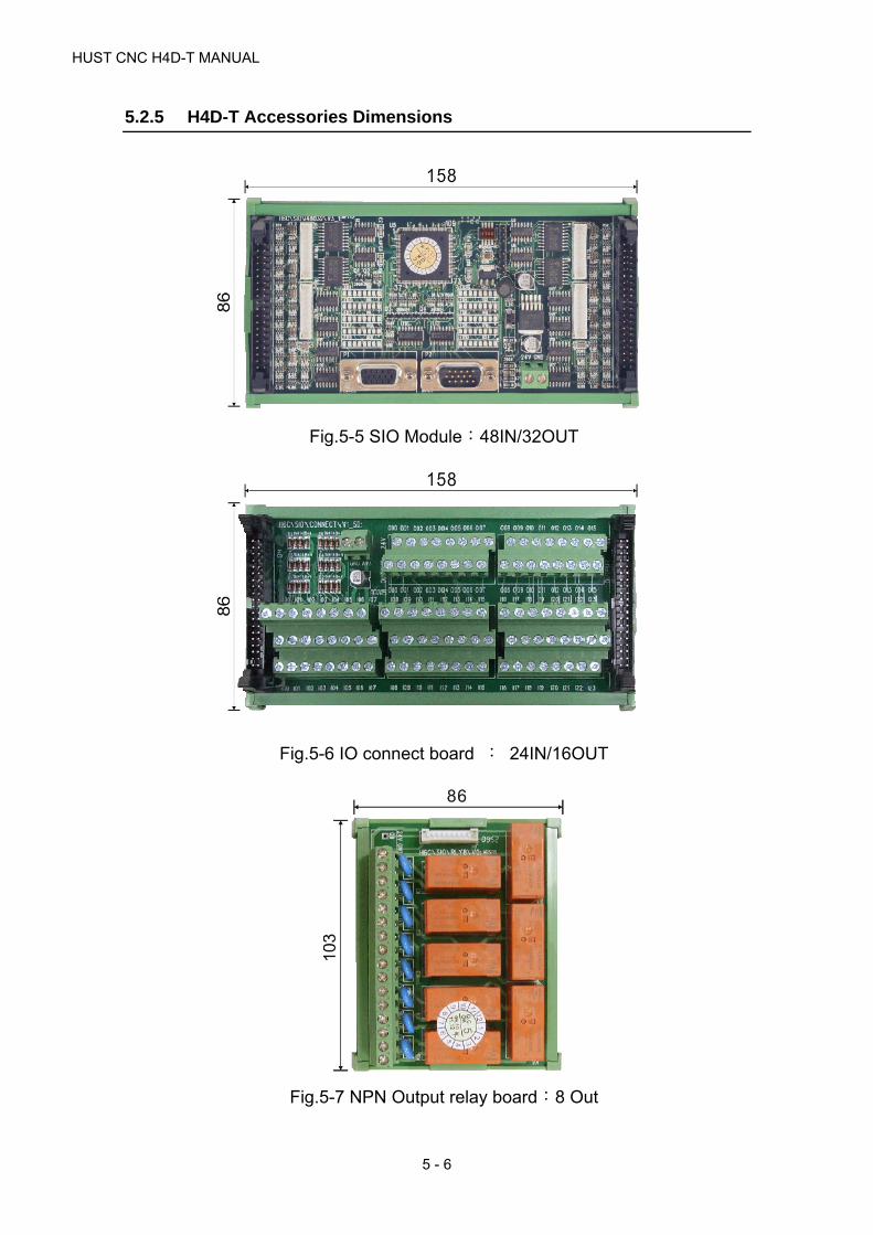
HUST CNC H4D-T MANUAL
5 - 6
5.2.5 H4D-T Accessories Dimensions
Fig.5-5 SIO Module:48IN/32OUT
Fig.5-6 IO connect board : 24IN/16OUT
Fig.5-7 NPN Output relay board:8 Out

5 CONNECTIONS
5 - 7
Fig.5-8 AC Power output module board:8 Out
Fig.5-9 DC Power module board:8 Out
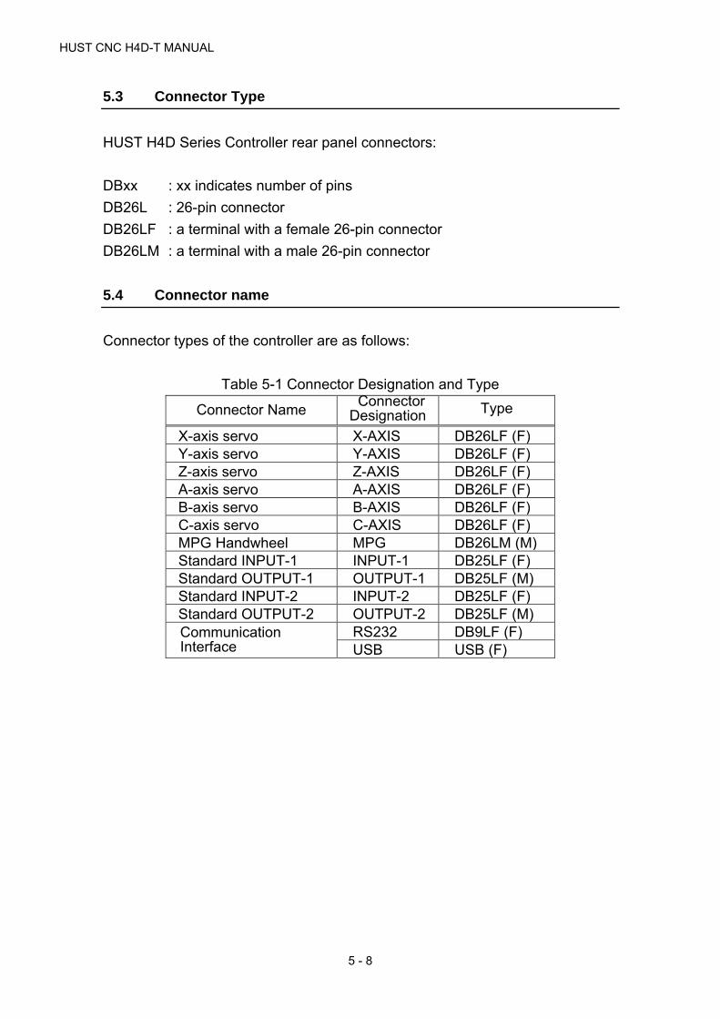
HUST CNC H4D-T MANUAL
5 - 8
5.3 Connector Type
HUST H4D Series Controller rear panel connectors:
DBxx : xx indicates number of pins
DB26L : 26-pin connector
DB26LF : a terminal with a female 26-pin connector
DB26LM : a terminal with a male 26-pin connector
5.4 Connector name
Connector types of the controller are as follows:
Table 5-1 Connector Designation and Type
Connector Name Connector
Designation Type
X-axis servo X-AXIS DB26LF (F) Y-axis servo Y-AXIS DB26LF (F) Z-axis servo Z-AXIS DB26LF (F) A-axis servo A-AXIS DB26LF (F) B-axis servo B-AXIS DB26LF (F) C-axis servo C-AXIS DB26LF (F) MPG Handwheel MPG DB26LM (M) Standard INPUT-1 INPUT-1 DB25LF (F) Standard OUTPUT-1 OUTPUT-1 DB25LF (M) Standard INPUT-2 INPUT-2 DB25LF (F) Standard OUTPUT-2 OUTPUT-2 DB25LF (M) Communication Interface
RS232 DB9LF (F) USB USB (F)

5 CONNECTIONS
5 - 9
5.5 Connector Pin-out Definition
DB26LF (F)
Table 5-2 HUST H4D Axis Connector Pin
Pin No Definition Description1 /A /A phase input2 A A phase input3 B B phase input4 /B /B phase input5 Z Z phase input6 /Z /Z phase input7 VCMD 0~10V analog command
8 GND 5V GND
(V-command、Torgue & +5V GND) 9 5V +5V Power10 TOG Torgue input11 - -12 - -13 - -14 - -15 - -16 - -17 IN-49 Group 2 Input signal ※Note 18 OUT-49 Group 2 Output signal ※Note 19 Pulse+ 20 Pulse- 21 Sign+ Pulse Direction+22 Sign- Pulse Direction -23 IN-48 Group 1 Input signal ※Note 24 OUT-48 Group 1 Output signal ※Note 25 24V +24V Power
26 24VGND24V GND
I/O & +24V GND
※ Note: Z axis group 1 I/O address at IN-52(pin23) OUT-52(pin24) Z axis group 2 I/O address at IN-53(pin17) OUT-53(pin18) ※ Output current at O: 30mA (H6D\CPU\V6_1 : 50mA)

HUST CNC H4D-T MANUAL
5 - 10
* MPG (H4D)
DB26LM (M)
Table 5-3 H4D <MPG> Definition
PinNo Definition Description MPG1 MPG2 DA1 DA2 AD1 AD2 G311 A1 A phase output (MPG1) ● 2 B1 B phase output (MPG1) ● 3 A2 A phase output (MPG2) ● 4 B2 B phase output (MPG2) ●
5 G31 IN Inputs signal to control high-speed axial stop ●
6 GND
5V GND MPG、AD/DA & +5V
GND ● ● ● ● ● ● 7
8 9 5V +5V Power ● ● 10 IN-86 Group 18 input signal 11 IN-87 Group 19 input signal
12 DA1 0~10V analog command 1 ●
13 DA2 0~10V analog command 2 ●
14 AD1 ±10V analog command Input 1 ●
15 AD2 ±10V analog command Input 2 ●
16 17 D+ CANOpen Signal 18 D- CANOpen Signal 19 IN-80 Group 12 input signal 20 IN-81 Group 13 input signal 21 IN-82 Group 14 input signal 22 IN-82 Group 15 input signal 23 IN-84 Group 16 input signal 24 IN-85 Group 17 input signal 25 24V +24V Power
26 24VGND 24V GND I/O、G31、+24VGND ●
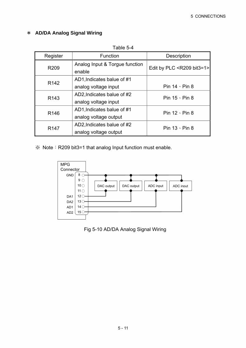
5 CONNECTIONS
5 - 11
* AD/DA Analog Signal Wiring
Table 5-4
Register Function Description
R209 Analog Input & Torgue function
enable Edit by PLC <R209 bit3=1>
R142 AD1,Indicates balue of #1
analog voltage input Pin 14、Pin 8
R143 AD2,Indicates balue of #2
analog voltage input Pin 15、Pin 8
R146 AD1,Indicates balue of #1
analog voltage output Pin 12、Pin 8
R147 AD2,Indicates balue of #2
analog voltage output Pin 13、Pin 8
※ Note:R209 bit3=1 that analog Input function must enable.
Fig 5-10 AD/DA Analog Signal Wiring
MPG Connector
GND
DA1
DA2
AD1
AD2
8
9
10
11
12
13
14
15
ADC input ADC input DAC output DAC output

HUST CNC H4D-T MANUAL
5 - 12
5.5.1 G31 INPUT Control signals
Contol High-Speed axial stop, responding in 0.5 μsec.
Table 5-5 Settings for
related Parameters and
Registers
Description
R250
Setting = 0, I-bit Input signal is an ascending (0→1) trigger signalSetting = 1, I-bit Input signal is a descending (1→0) trigger signalSetting = 2, I-bit Input signal is a Normal Open (0) signal Setting = 3, I-bit Input signal is a Normal Close (1) signal
Fig 5-11 G31 INPUT Signal Wiring
MPG Connector
G31IN
24VGND
1
2
3
4
5
26
G31 Hardware stop signal

5 CONNECTIONS
5 - 13
5.5.2 Axial Control, pin assignment and wiring
Connect servo driver to axial-control connector as shown in Fig.5-12 (pin
assignment identical for all axes).
Fig.5-12 Wiring for Axial Control
1. Isolated twist-pair cables shall be used.
2. Pay special attention to Pins 1-4 of the axial connection. In case the motor
runs scattering, alter the terminal A with the terminal B at the driver end.
3. HUST miller controller, when voltage-command type servo motor is used,
you need to set the Follow Error checking function. (Not applicable to pulse
commands.)
(a) Parameter 533 = 4096 check the value of Follow Error.
(b) Parameter 543 = 63 check Follow Error of the axis X/Y/Z/A/B/C
simultaneously (set by BIT: Bit0=1 for X-axis, Bit1=1 for Y-axis……).
(c) When the ERROR COUNT of the actual feedback of X-axis motor
>4096, the system will issue an error message.
4. In H4D-T Controller, connect Spindle 1 to C-axis, Spindle 2 to A-axis and
Spindle 3 to B-axis; and other axes will be connected according to the
wiring method shown.
Servo connections dependent on different maker
Displacement command -10 ~
0V
1
2
3
4
5
6
7
8
10
19
20
21
22
/A
A
B
/B
Z
/Z
VCMD
GND
TOG
Pulse+
Pulse-
Sign+
Sign-
AXIS
Servo signal

HUST CNC H4D-T MANUAL
5 - 14
5.5.3 Wiring of Manual Pulse Generator (MPG)
HUST H4D series can share 2 units of Manual Pulse Generators
simultaneously.
If the Tool traveling direction is opposite to that indicated for Manual Pulse
Generator, then Parameter 518 can be used to change the Hand Wheel
direction.(If the machine uses two hand wheels, hand wheels will be changed at
the same time.)
Operation description of Hand Wheel 2:
In PLC, C237=1. (refer to MPG2 pin)
Select the axis to be controller with R243.
Adjust the multiple with R245.
MPG Pin 6、7、8 are 5V GND.
Fig. 5-13 Manual Pulse Generator (MPG) Wiring
2nd hand wheel
MPG
A2
B2
1
2
3
4
5
6
8
9
GND
+5V
MPG 2
0V+5V A B
MPG
1
2
3
4
5
6
8
9
A1
B1
GND
+5V
MPG 1
0V+5V A B

5 CONNECTIONS
5 - 15
5.5.4 Wiring of Spindle Control
There are 2 types of Spindle Control:
(1) Voltage Command type
(2) Pulse Command type
* Voltage Command type
Fig.5-14 Spindle voltage command control-closed circuit wiring (servo)
Fig.5-15 Spindle Voltage Command Control- Open circuit wiring (Inverter)
7
8
9
1
2
3
4
5
6
Case GND
Servo Driver
Spindle 7
8
9
1
2
3
4
5
6
VCOM
GND
+5V
/A
A
B
/B
Z
/Z
Case GND
Encoder
Spindle
VCOM
GND
+5V
/A
A
B
/B
Z
/Z
Inverter
Extemal Encoder

HUST CNC H4D-T MANUAL
5 - 16
* Pulse Command Type
Fig.5-16 Spindle pulse command control- closed circuit wiring (servo)
Fig.5-17 Spindle pulse command control- closed circuit wiring (Inverter)
19
20
21
22
1
2
3
4
5
6
9
8
Case GND
Servo Driver
19
20
21
22
1
2
3
4
5
6
8
Pulse+
Pulse-
Sign+
Sign-
/A
A
B
/B
Z
/Z
GND
Spindle
Case GND
Encoder
External Encoder
Pulse+
Pulse-
Sign+
Sign-
/A
A
B
/B
Z
/Z
+5V
GND
Spindle
Inverter
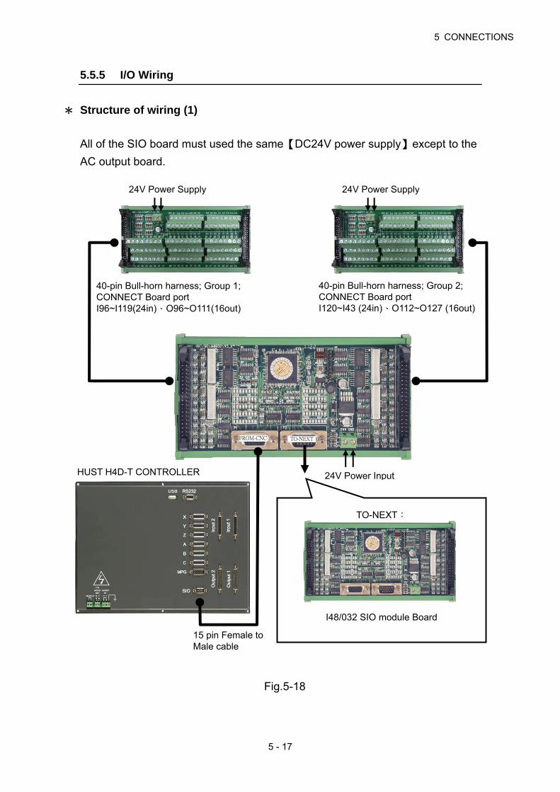
5 CONNECTIONS
5 - 17
5.5.5 I/O Wiring
* Structure of wiring (1)
All of the SIO board must used the same【DC24V power supply】except to the
AC output board.
Fig.5-18
15 pin Female to Male cable
HUST H4D-T CONTROLLER
40-pin Bull-horn harness; Group 2; CONNECT Board port I120~I43 (24in)、O112~O127 (16out)
40-pin Bull-horn harness; Group 1; CONNECT Board port I96~I119(24in)、O96~O111(16out)
FROM-CNC TO-NEXT
24V Power Supply 24V Power Supply
24V Power Input
TO-NEXT:
I48/032 SIO module Board

HUST CNC H4D-T MANUAL
5 - 18
* Structure of wiring (2)
All of the SIO board must used the same【DC24V power supply】except to the
AC output board.
Fig.5-19
24V Power Supply 24V Power Supply
40-pin Bull-horn harness; Group 2; CONNECT Board port I120~I43 (24in) O112~O127 (16out)
40-pin Bull-horn harness; Group 1; CONNECT Board port I96~I119(24in) O96~O111(16out) GND 24V
1. Use in combination as required 2. 10 pin white connecto
3. Can be connected to 3 optional boards 4. Can be connect 4 modules maximum . 5. NPN RELAY BOARD :provide 8 dry contacts. Max. current for each output of
he PCB is 1A . 6. AC power output module board:provide 8 AC110V outputs. M ax. current for
each output of the PCB is 1A. 7. DC power module board:provide 8 DC24V outputs. Max. current for each
output of the PCB is 1A .
Accessories:
8 OUT RELAY BOARD AC POWER OUTPUT MODULE BOARD
DC POWER OUTPUT MODULE BOARD

5 CONNECTIONS
5 - 19
5.5.6 Input/Output wiring schematic
The input signals are the messages transmitted to the Controller from the external
device. These signals can be generated by push button, Limit Switch, Relay Board
connection or Proximity Switch, etc.
The output signals are the messages transmitted to external working machine
from the Controller, which are used to drive the Relay of the Working Machine
and the LED display of the Controller.
Input/Output Interface
The Controller must link with other accessories through SIO Module Board so as to
control the actions of external I/O, power output and axis control module.
* I/O Connect Board (PC Board No.:H6D\SIO\IO\V1_2, AB852)
Fig 5-20
1. I/O connect board controls 24 input terminals and 16 output terminals.
2. Output control is by 0V output.
3. An INPUT can be of NPN type or PNP type.
4. When NPN and PNP are in use at the same time,
(1) NPN:the input voltage at I is 0V.
(2) PNP:the input voltage at I is 24V.
5. Input current at I: 3.6mA
6. Output current at O: 100mA (H6D\CPU\V6_1 : 250mA).

HUST CNC H4D-T MANUAL
5 - 20
Table 5-21 I/O Connector Pin Assignment (NPN-PNP Type)
* SIO module Board (H6C\SIO\I48O32\V3_1, AE712)
Fig.5-22
Serial Input/Output Module (SIO)
1. The SIO Module Board is provided with 48 input/32 output points
respectively.
(a) A maximum of 4 boards can be linked in providing maximum 256
input/176 output points respectively.
(b) It can be linked with Auxiliary Panel (Panel 2).
2. The module can work with the following external components:
(a) Standard input/output CONNECT panel (24 Input/16 Output).
(b) 8 Out Relay boards.
Output Pin Assignment (Male) Input Pin Assignment (Female)
+24V
+24V
24V GND
24V GND
14
15
16
17
18
19
20
21
22
23
24
25
1
2
3
4
5
6
7
8
9
10
11
12
13
00
01
02
03
04
05
06
07
08
09
10
11
12
13
14
15
25
24
23
22
21
20
19
18
17
16
15
14
13
12
11
10
9
8
7
6
5
4
3
2
1
12
11
10
09
08
07
06
05
04
03
02
01
00
24V GND
23
22
21
20
19
18
17
16
15
14
13

5 CONNECTIONS
5 - 21
(c) 8 Out DC power boards.
(d) 8 Out AC power boards.
(e) 8 Out Axis Control Modules: To control the Servo or Step Motor.
3. When using with Universal Auxiliary Panel, it will occupy the I/O position of
Panel 2.
4. The Dip Switch is used to define the I/O starting position of SIO Module Board.
Explanation of SIO MODULE BOARD:
LED-lamp (Input):
LED-lamp (Output):
SWITCH:
Fig.5-23
1. LED Indicator:
I-Point Signal LED Indicator (Green) : 3 groups each for upper and lower
rows with each group containing 8 lamps, which makes a total of 48 lamps.
O-Point Signal LED Indicator (Red) : 2 groups each for upper and lower
rows with each group containing 8 lamps, which makes a total of 32 lamps.
1
3
2
FROM-CNC TO-NEXT
LED
24V external power input
Group 1 CONNECT board port
LED
Group 2 CONNECT board port

HUST CNC H4D-T MANUAL
5 - 22
2. Dip Switch : For setting the SIO Module Board and I/O staring signal
position.
Table 5-6 Dip Switch – I/O Module Corresponding Positions
MODULE Switch 1 Switch 2 Switch 3 Switch 4 IN range OUT range
1st 0 0 0 0 I096 ~ I143 O096 ~ O127
2nd 1 1 0 0 I144 ~ I191 O144 ~ O175
3rd 0 1 1 0 I192 ~ I239 O192 ~ O223
4th 1 0 0 1 I240 ~ I255 O240 ~ O255
※ Module Board 4 can control 16 unit of Inputs and 16 units of Outputs.
I/O related scope when using with Operation Panel 2:
Table 5-7 Stand operator panel I/O Corresponding Scope
IO range
Board Switch 1 Switch 2 Switch 3 Switch 4 Input range Output Range
1st 0 0 0 0 I096 ~ I143 O096 ~ O127
2nd General Purpose Secondary Control Panel I144 ~ I191 O144 ~ O175
3rd 0 1 1 0 I192 ~ I239 O192 ~ O223
4th 1 0 0 1 I240 ~ I255 O240 ~ O255
※ When use operator panel, that SIO address Occupancy.
ON DIP
1 2 3 4 SW

5 CONNECTIONS
5 - 23
* Connect board (H6C\SIO\CONNECT\V1_SD, AB705)
1. I/O connect board controls 24 input terminals and 16 output terminals.
2. Output control is by 0V output.
3. An INPUT can be of NPN type or PNP type.
4. When NPN and PNP are in use at the same time,
(1) NPN:the input voltage at I is 0V.
(2) PNP:the input voltage at I is 24V.
5. Input current at I: 6mA
6. Output current at O: 100mA
Fig.5-24
* 8 out relay Board (H6C\SIO\RLY8\V0, AB585)
1. Max. current for each output of the PCB is 1A
2. For a max. current > 1A, use other relays.
3. Contacts on the RELAY adaptor board are dry contacts
Fig.5-25
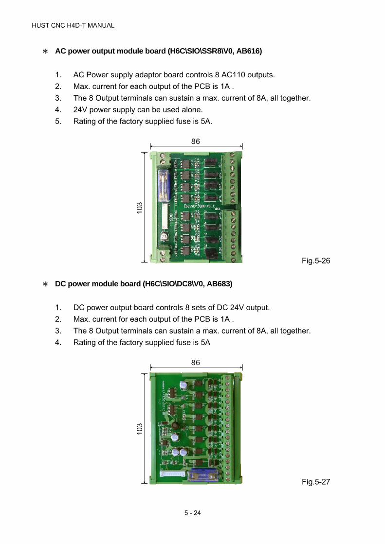
HUST CNC H4D-T MANUAL
5 - 24
* AC power output module board (H6C\SIO\SSR8\V0, AB616)
1. AC Power supply adaptor board controls 8 AC110 outputs.
2. Max. current for each output of the PCB is 1A .
3. The 8 Output terminals can sustain a max. current of 8A, all together.
4. 24V power supply can be used alone.
5. Rating of the factory supplied fuse is 5A.
Fig.5-26
* DC power module board (H6C\SIO\DC8\V0, AB683)
1. DC power output board controls 8 sets of DC 24V output.
2. Max. current for each output of the PCB is 1A .
3. The 8 Output terminals can sustain a max. current of 8A, all together.
4. Rating of the factory supplied fuse is 5A
Fig.5-27
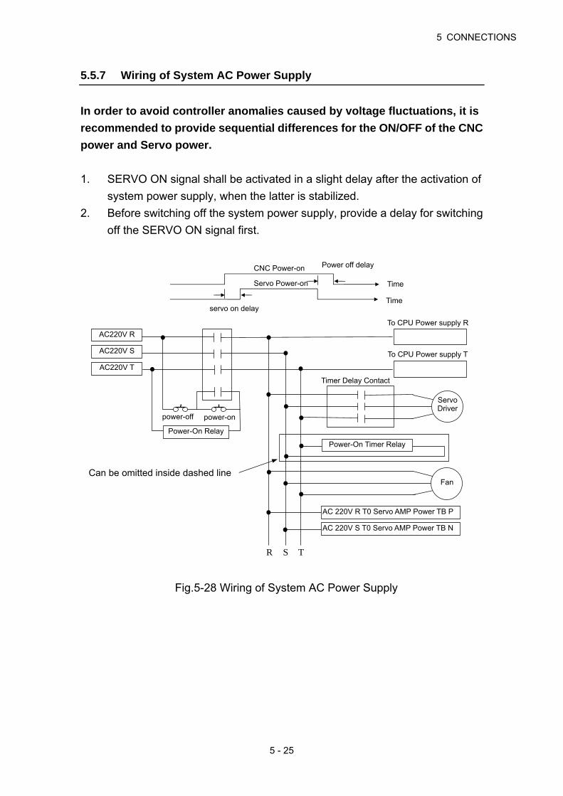
5 CONNECTIONS
5 - 25
5.5.7 Wiring of System AC Power Supply
In order to avoid controller anomalies caused by voltage fluctuations, it is
recommended to provide sequential differences for the ON/OFF of the CNC
power and Servo power.
1. SERVO ON signal shall be activated in a slight delay after the activation of
system power supply, when the latter is stabilized.
2. Before switching off the system power supply, provide a delay for switching
off the SERVO ON signal first.
Fig.5-28 Wiring of System AC Power Supply
CNC Power-on
Time Servo Power-on
Time servo on delay
Power off delay
R TS
To CPU Power supply R
To CPU Power supply T
AC220V R
AC220V S
AC220V T
Fan
power-off power-on
Power-On Relay
Power-On Timer Relay
AC 220V R T0 Servo AMP Power TB P
AC 220V S T0 Servo AMP Power TB N
Servo Driver
Timer Delay Contact
Can be omitted inside dashed line
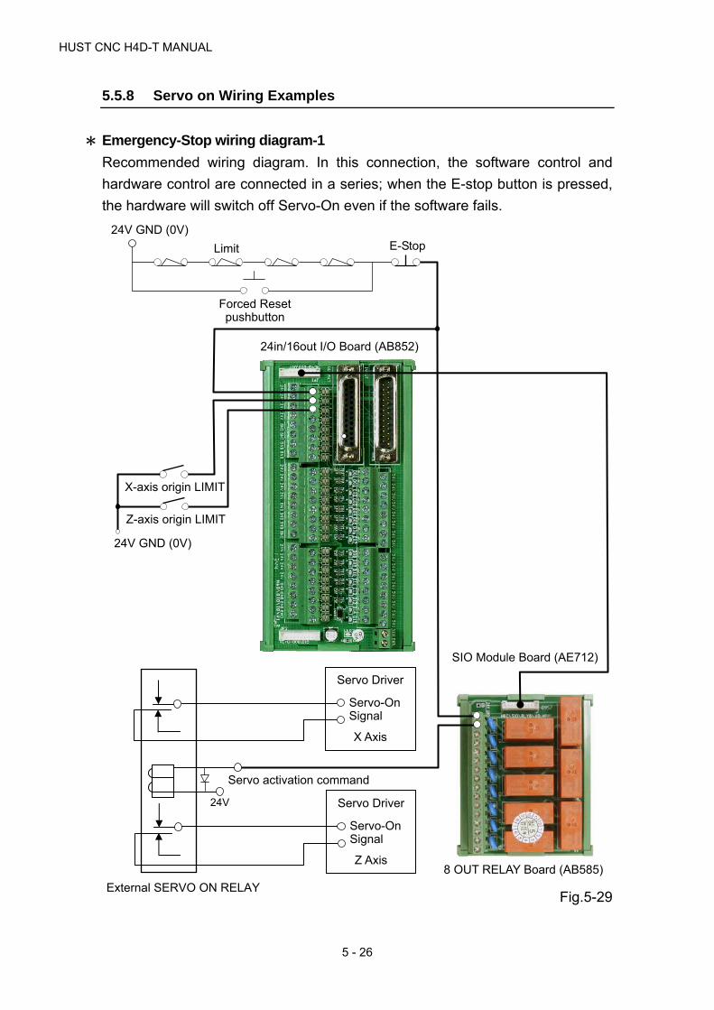
HUST CNC H4D-T MANUAL
5 - 26
5.5.8 Servo on Wiring Examples
* Emergency-Stop wiring diagram-1
Recommended wiring diagram. In this connection, the software control and
hardware control are connected in a series; when the E-stop button is pressed,
the hardware will switch off Servo-On even if the software fails.
Fig.5-29
24V GND (0V)
Limit E-Stop
Forced Reset pushbutton
8 OUT RELAY Board (AB585)
SIO Module Board (AE712)
24in/16out I/O Board (AB852)
External SERVO ON RELAY
24V
Servo activation command
Servo Driver
Z Axis
Servo-OnSignal
Servo Driver
X Axis
Servo-OnSignal
24V GND (0V)
X-axis origin LIMIT
Z-axis origin LIMIT

5 CONNECTIONS
5 - 27
* Emergency-Stop wiring diagram-2
Convenient Wiring Diagram.
Fig.5-30
24V GND (0V)
Limit E-Stop
Forced Reset pushbutton
24in/16out I/O Board (AB852)
External SERVO ON RELAY
24V
Servo activation command
Servo Driver
Z Axis
Servo-OnSignal
Servo Driver
X Axis
Servo-OnSignal
24V GND (0V)
X-axis origin LIMIT
Z-axis origin LIMIT

HUST CNC H4D-T MANUAL
5 - 28
* Emergency-Stop wiring diagram-3
Convenient Wiring Diagram.
Fig.5-31
24in/16out I/O Board (AB852)
24V GND (0V)
Limit E-Stop
Forced Reset pushbutton
8 OUT RELAY Board (AB585)
Servo Driver
X Axis
Servo-On Signal
Servo Driver
Z Axis
Servo-On Signal
24V GND (0V)
X-axis origin LIMIT
Z-axis origin LIMIT

5 CONNECTIONS
5 - 29
* Other Wiring – Example 1
Fig.5-32
1st I/O Connect Board
25pin x2 M/F Connetor
I0~I23(24in)
O0~O15(16out)
O15
Output 0V
Spark Killer
External Relay
24V
O00
Output 0V
Spark Killer
External Relay
24V
HUST H4D-T CONTROLLER

HUST CNC H4D-T MANUAL
5 - 30
* Other Wiring – Example 2: Dry Contact Output
Fig.5-33
COM 01 COM 02 COM 03 COM 04 COM 05 COM 06 COM 07 COM 08
AC 220V
When Controller is O00=1, it
will output AC 220V voltage.
AC 220V
Transformer
10pin Row Cable, 1st O00~O07 (8out)
1st I/O Connect Board
25pin x2 M/F Connector
I0~I23(24in) O0~O15(16out)

5 CONNECTIONS
5 - 31
As each COM point is not inter-connected, they should be wired
individually when using.
The external Relay may not be connected that the Relay Board can be
used independently.
As per the figure above, when the Controller is O00=1, it outputs 0V and
COM will be connected with 01 in the meantime.

HUST CNC H4D-T MANUAL
5 - 32
* Other Wiring – Example 3: Dry Contact Output
Fig.5-34
COM01 COM 02 COM 03 COM 04 COM 05 COM 06 COM 07 COM 08
AC 220V
When Controller is
O00=1, it will output
AC 220V voltage.
AC 220V
Transformer
40pin Row cable, 1st Connect board I0~I23 (24in) O0~O15 (16out)
24V Power Input
24V Power Supply

5 CONNECTIONS
5 - 33
* Other Wiring – Example 4: AC Power Output
Single Output Point: The maximum current to be sustained by AC Power Output
Board will be 1A.
When using 8 output points simultaneously: The maximum current to be
sustained by AC Power Output Board will be 8A.
Fig.5-35
※ As per the figure, when the
Controller is O000=1 (AC01), it
will output AC220V voltage.
※ At DC24V Power Input End: It
can use an independent Power
Provider without sharing with
24V of the module board.
※ Default Fuse Withstand
Current: 5A
AC220V
Voltage Output
10-pin Soft
Harness AC220V
Power Input DC24V
Power Input
DC24V Power Supply

HUST CNC H4D-T MANUAL
5 - 34
* Other wiring – Example 5: DC Power Output
Single Output Point: The maximum current to be sustained by DC Power Output
Board will be 1A.
When using 8 output points simultaneously: The maximum current to be
sustained by DC Power Output Board will be 8A.
Fig.5-36
DC24V Power Supply
※ As per the figure, when the
Controller is O015=1 (07),
then it will output DC 24V
voltage.
※ Default Fuse Withstand
Current: 5A
10-Pin Soft Harness
DC24V
Voltage Output
DC24V
Voltage Input
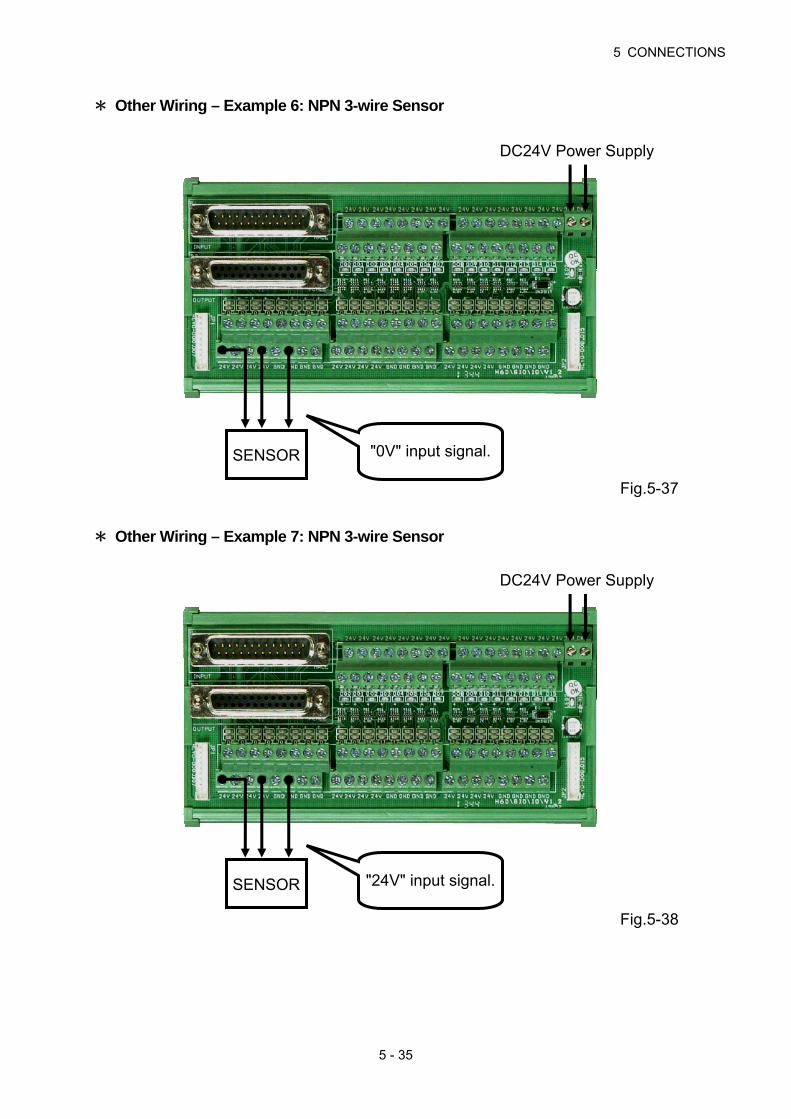
5 CONNECTIONS
5 - 35
* Other Wiring – Example 6: NPN 3-wire Sensor
Fig.5-37
* Other Wiring – Example 7: NPN 3-wire Sensor
Fig.5-38
DC24V Power Supply
"0V" input signal.SENSOR
DC24V Power Supply
"24V" input signal.SENSOR

HUST CNC H4D-T MANUAL
5 - 36
* RS232C Connector, pin-out assignment and wiring
Fig.5-39 shows the connection between the HUST H6D Serial Controller and the
computer (PC). When carrying out the wiring, take the following precautions:
1. The RS232C cable shall not exceed a length of 15m.
2. In case of existence of massive noise generators (e.g., EDM processor,
welding machine, etc.) in the vicinity, Twist-pair type cables shall be used,
or such an environment shall be avoided. The controller and the PC shall
NOT share a common power socket with an EDM or welding machine.
3. Make sure the voltage of the interface at the PC end is within the range of
10~15V.
Fig.5-39
HUST Controller end PC end COM
HUST Controller end PC end COM
DB9LM
CONNECTOR
DB25LF
CONNECTO
2
3
5
7
8
TXD
RXD
SG
CTS
RTS
3
2
7
5
4
RXD
TXD
SG
RTS
CTS
DC DC
DB9LM CONNECTOR
DB9LF CONNECTOR
2 RXD 3 TXD 4 DTR 5 SG 6 DSR 7 RTS 8 CTS
TXD 2 RXD 3 DSR 4 SG 5 DTR 6 CTS 7 RTS 8

6 ERROR MESSAGES
6 - 1
6 ERROR MESSAGES
When an error occurs in the execution of an HUST H4D-T series controller, an
error message will appear in the LCD screen as shown in Fig.6-1 & Fig.6-2.
Possible error messages regarding the HUST H4D-T series controller, together
with their remedies, are described as follows.
Fig 6-1 Error Message Display 1
Fig 6-2 Error Message Display 2

HUST CNC H4D-T MANUAL
6 - 2
Error Code
Details Causes
01 Incorrect MCM parameter setting.
B Each axis returned to origin, GRID limit of the servo motor >1024.
Remedy:
1. Check MCM parameter for correct setting or double-press to enter
"MDI" mode, execute commend G10 P1000 to delete parameter, then
re-set parameter.
2. If the controller has rested for more than a year without switching on, the
internal memory will disappear. The controller will display [BT1] indicating
the battery power is low and you need to contact the dealer.
Error
Code Details Causes
02 X~C Excessive error in Axial Follow.
S Excessive error in Spindle Follow (>3072).
Remedy:
1. Check the program for excessive setting of F value;
2. Check whether the Resolution setting is correct (Check items 241~ 252,
MCM parameters);
3. Check if machine or motor is obstructed. Check the wiring.
4. Check Parameter 533; the default value is 4096.
Error
Code Details Causes
03 L M99 count exceeds maximum limit
(#10922>#10921).
Message:
Setting of the M02, M30, or M99 counter exceeds the limit of system variables,
10921.
Remedy:
1. Double press “0” button in AUTO mode to clear the counting value.
2. Clear the system variable count of 10922 so it returns to 0, then press
to remove the error.

6 ERROR MESSAGES
6 - 3
3. Or run G10 P201 command in AUTO or MDI mode, for clearing the system
variable (10921) to 0, then press
again to clear the error.
Error Code Details Causes
04
A U USB/SDC error —FR_DISK_ERRB USB/SDC error —FR_INT_ERRC USB/SDC error —FR_NOT_READYD USB/SDC error —FR_NO_FILEE USB/SDC error —FR_NO_PATHF USB/SDC error —FR_INVALID_NAME G USB/SDC error —FR_DENIEDH USB/SDC error —FR_EXISTI USB/SDC error —FR_INVALID_OBJECT J USB/SDC error —FR_WRITE_PROTECTED K USB/SDC error —FR_INVALID_DRIVE L USB/SDC error —FR_NOT_ENABLED M USB/SDC error —FR_NO_FILESYSTEM N USB/SDC error —FR_MKFS_ABORTED O USB/SDC error —FR_TIMEOUT
Remedy:
1. Make sure the USB is of FAT format and the file extension of the transferred
program is correct.
2. Consult the dealer or the manufacturer.
Error Code Details Causes
08
D Incorrect Data Address retrieved when executing ZDNC.
M MDI command error (commend size greater than 128bytes).
E Size of current program segment exceeds 128bytes.Remedy:
Check the program and make sure that each segment is within 128 characters.
Error Code Details Causes
10
O RS232 error —OVERRUN ERRORP RS232 error —PARITY ERRORF RS232 error —FRAME ERRORB RS232 error —BREAK ERRORN RS232 error —OTHER ERROR
Remedy:
1. Check transmission speed of controller communication port, i.e., parameter
520 of MCM is the same value as that of PC or man-machine interface.

HUST CNC H4D-T MANUAL
6 - 4
2. Check the communication cables between the controller and the PC or the
man-machine interface.
Error Code Details Causes
11
1 CHECKSUM error of programA SUM error in the Start-up checkD Program Memory address error (DOWN MODE) F Program Memory is fullU Program Memory address error (UP MODE)
Remedy:
Double-press button to enter MDI mode. Run G10 P2001 command to
clear all the program data, check the memory battery. If the controller displays
battery low (BT1) message, you need to replace the battery (data in the memory
will be lost if the controller remains OFF for more than one year).
Error Code Details Causes
12
The size of the burn-in program exceeds the limitH4 Series:56k H6 Standard: 56k= 896 lines, 64bytes per line H6 Turning/Milling: 56k +128k (saving capacity for function key) =2944 lines. Since the current limit for burn-in is 128k, therefore the maximum size is 128k (=2048 lines).
N The declared command exceeds 20 program lines (G11, G12, G04, M-code).
L L error in “G10 P0920 Lxxxx”(L shall not be empty, and 0<=LA<1000)
P Program specified by Lxxxx in “G10 P0921 Lxxxx” has not been declared.
Remedy:
1. Check the program for incorrect writing.
2. Check the capacity for the program.
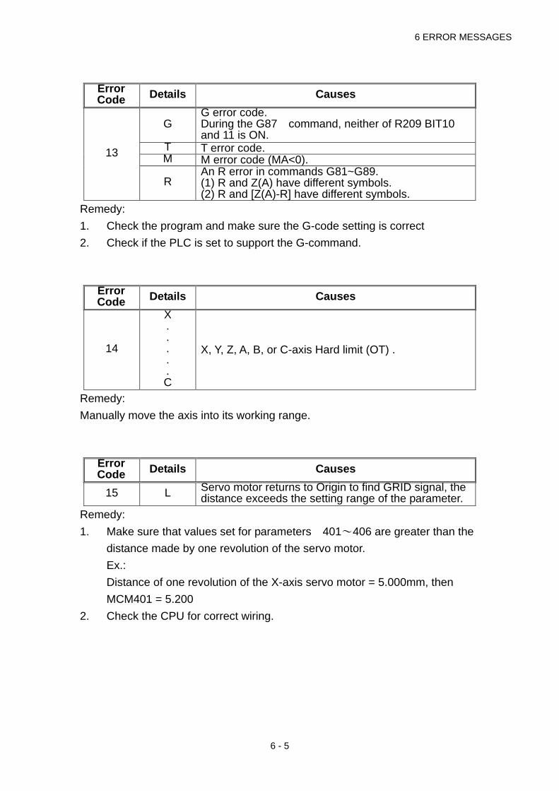
6 ERROR MESSAGES
6 - 5
Error Code Details Causes
13
G G error code.During the G87 command, neither of R209 BIT10 and 11 is ON.
T T error code.M M error code (MA<0).
R An R error in commands G81~G89. (1) R and Z(A) have different symbols. (2) R and [Z(A)-R] have different symbols.
Remedy:
1. Check the program and make sure the G-code setting is correct
2. Check if the PLC is set to support the G-command.
Error Code Details Causes
14
X. . . . . C
X, Y, Z, A, B, or C-axis Hard limit (OT) .
Remedy:
Manually move the axis into its working range.
Error Code Details Causes
15 L Servo motor returns to Origin to find GRID signal, the distance exceeds the setting range of the parameter.
Remedy:
1. Make sure that values set for parameters 401~406 are greater than the
distance made by one revolution of the servo motor.
Ex.:
Distance of one revolution of the X-axis servo motor = 5.000mm, then
MCM401 = 5.200
2. Check the CPU for correct wiring.

HUST CNC H4D-T MANUAL
6 - 6
Error Code Details Causes
18
There have some error in programming occurs when executing the program in AUTO mode.
C
Error of copied segment in the program; cause for the error may be one of the following: 1. Non-existence of the source program. 2. Starting line-no. > Ending line-no. in the source
program 3. Starting line-no. > total line-number of the source
program 4. Ending line-no. > total line-number of the source
program 5. Missing program number in the pasting target. 6. Starting line-no. of the pasting target > total
line-number. 7. Memory is full when the pasting content has not
been fully pasted. 8. Source program = pasting target program no.;
and, starting line of source program <= starting line no. of pasting target <= ending line no. of source program.
M Trigger C25 segment data retrieval error: cannot find initial address of specified segment.
T Failure in finding initial address of specified program.
Q M95Qxxx error (QA is out of 0~127, or QA specified program does not exist).
L M99 jump-back program error (G10P301 specified line-no. error).
P Empty CALL in sub-program. (G60…G63) Remedy:
1. Check the ending of the program and add M02 or M03 segment.
2. Check the program for excessive size.
3. Check for any error in the segment content and in serial setting (N) of the
specified segment.
Error Code Details Causes
20
X. . . . . C
X, Y, Z, A, B, C- axis software OT limit.
N Number of position limits set in the dynamic range of the software exceeds 4000.
Remedy:
Check the program or re-set MCM parameters 581~586 and 601~606, the
software travel limits.

6 ERROR MESSAGES
6 - 7
Error Code Details Causes
22 Emergency Stop (C002=1).
Remedy:
After removal of error, turn off the Emergency Stop pushbutton, followed by
pressing the RESET button.
Error Code Details Causes
24 Memory Stack error.
Remedy:
Check for repetitive use of CALL subroutine.
Error Code Details Causes
25
G02/G03 command error (Radius of starting point unequal to radius of ending point).
R Incorrect input format of R in G02/G03No displacement in both axes of arc interpolation, or (R<0 in lathe mode).
L 2*[RAR]>[LENGTH].G I, J, R not specified in G02/G03 command.
Remedy:
Check the program. Re-calculate arc intersection and verify its coordinates.
Error Code Details Causes
27
X. . . C
For X~C, when C28=1 and R190 0, R190 < the deceleration distance of respective axis after the motor receives the INPUT of G31.
Remedy:
1. Check if R190 setting is too short so that it is less than the acceleration
distance.
2. Shorten the acceleration/ deceleration time setting (Motor load to be
considered).
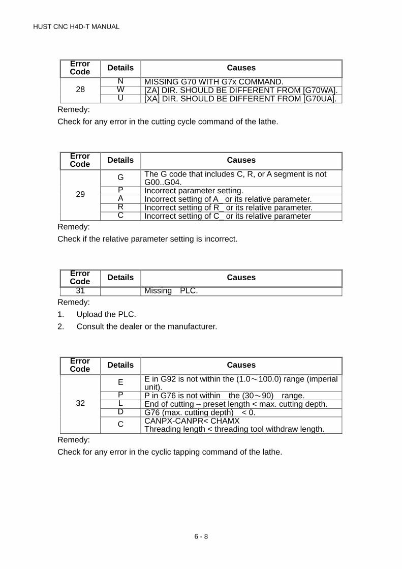
HUST CNC H4D-T MANUAL
6 - 8
Error Code Details Causes
28 N MISSING G70 WITH G7x COMMAND.W [ZA] DIR. SHOULD BE DIFFERENT FROM [G70WA].U [XA] DIR. SHOULD BE DIFFERENT FROM [G70UA].
Remedy:
Check for any error in the cutting cycle command of the lathe.
Error Code Details Causes
29
G The G code that includes C, R, or A segment is not G00..G04.
P Incorrect parameter setting.A Incorrect setting of A_ or its relative parameter. R Incorrect setting of R_ or its relative parameter. C Incorrect setting of C_ or its relative parameter
Remedy:
Check if the relative parameter setting is incorrect.
Error Code Details Causes
31 Missing PLC.
Remedy:
1. Upload the PLC.
2. Consult the dealer or the manufacturer.
Error Code Details Causes
32
E E in G92 is not within the (1.0~100.0) range (imperial unit).
P P in G76 is not within the (30~90) range. L End of cutting – preset length < max. cutting depth. D G76 (max. cutting depth) < 0.
C CANPX-CANPR< CHAMXThreading length < threading tool withdraw length.
Remedy:
Check for any error in the cyclic tapping command of the lathe.

6 ERROR MESSAGES
6 - 9
Error Code Details Causes
33
4 Kxx=0 in G34.5 Kxx=0 in G35.6 Kxx=0 in G36.7 Pxx<=0 or Kxx=0 in G37.
Execute G35, G36, or G37 in lathe mode. Remedy:
Check for any error in K setting in commands G34~37 of the lathe.
Error Code Details Causes
36
B Header of USB/SDC file is not ‘O8001’. Header of USB/SDC file is not ‘O8002’.
C Header of MCM file is not ‘O9002’.
F Header of function key file is not ‘O9140’. Header of variable file is not ‘O9004’.
L Header of PLC file is not ‘O9003’.Size of PLC document exceeds upper limit.
P Input program no. exceeds 1000 (Oxxxx).
R LENGTH OR SUM ERROR#13245, #13246, #13247, #13248.
S Header of SYS file is not ‘O9100’.Size of SYS document exceeds upper limit.
T Header of TBL file is not ‘O9110’.W Input hex file is not in XXXX,0DH format.
Remedy:
Check for incorrect data transfer format.
Error Code Details Causes
37 NC ALARM (C007=1).
Remedy:
Check external control device, remove error and RESET.
Error Code Details Causes
38 Excessive screen display time (>3000ms).
Remedy:
1. Re-transfer screen data file.
2. Consult dealer or manufacturer.

HUST CNC H4D-T MANUAL
6 - 10
Error Code Details Causes
41 In Tool Offset mode, the command paths between 2 single blocks are 2 parallel lines.
42 OVER CUT 43 Insufficient distance between Start and End (<0.005).
45 C251=0, Between the single block that the radius of circular arc compensation < 0
46 In Tool Offset mode, the system fails to determine the center-of-arc when executing an arc command.
48 Radius of tool offset < 0.
49 Direction of tool tip in the lathe is not of the 0~9 type Number of segment of axial displacement is greater than 10
Remedy:
1. Check for any error in tool offset value.
2. Check the program for any error.
Error Code Details Causes
50 . . .
99
Customer-defined error alarm using G65.
Remedy:
Check for any error in the setting of G65, customer-defined error message.

7 MCM PARAMETERS
7 - 1
7 MCM (Machine Constant) PARAMETERS
MCM No.
Factory Default Setting
Unit Description Setting
1 0 mm G54 X-axis 1st Work coordinate (origin) 2 0 mm G54 Y-axis 1st Work coordinate (origin) 3 0 mm G54 Z-axis 1st Work coordinate (origin) 4 0 mm G54 A-axis 1st Work coordinate (origin) 5 0 mm G54 B-axis 1st Work coordinate (origin) 6 0 mm G54 C-axis 1st Work coordinate (origin) 7 0 mm G54 U-axis 1st Work coordinate (origin) 8 0 mm G54 V-axis 1st Work coordinate (origin) 9 0 mm G54 W-axis 1st Work coordinate (origin)
10-20 System Reserved! 21 0 mm G55 X-axis 2nd Work coordinate (origin) 22 0 mm G55 Y-axis 2nd Work coordinate (origin) 23 0 mm G55 Z-axis 2nd Work coordinate (origin) 24 0 mm G55 A-axis 2nd Work coordinate (origin) 25 0 mm G55 B-axis 2nd Work coordinate (origin) 26 0 mm G55 C-axis 2nd Work coordinate (origin) 27 0 mm G55 U-axis 2nd Work coordinate (origin) 28 0 mm G55 V-axis 2nd Work coordinate (origin) 29 0 mm G55 W-axis 2nd Work coordinate (origin)
30-40 System Reserved! 41 0 mm G56 X-axis 3rd Work coordinate (origin) 42 0 mm G56 Y-axis 3rd Work coordinate (origin) 43 0 mm G56 Z-axis 3rd Work coordinate (origin) 44 0 mm G56 A-axis 3rd Work coordinate (origin) 45 0 mm G56 B-axis 3rd Work coordinate (origin) 46 0 mm G56 C-axis 3rd Work coordinate (origin) 47 0 mm G56 U-axis 3rd Work coordinate (origin) 48 0 mm G56 V-axis 3rd Work coordinate (origin) 49 0 mm G56 W-axis 3rd Work coordinate (origin)
50-60 System Reserved! 61 0 mm G57 X-axis 4th Work coordinate (origin) 62 0 mm G57 Y-axis 4th Work coordinate (origin) 63 0 mm G57 Z-axis 4th Work coordinate (origin) 64 0 mm G57 A-axis 4th Work coordinate (origin) 65 0 mm G57 B-axis 4th Work coordinate (origin) 66 0 mm G57 C-axis 4th Work coordinate (origin) 67 0 mm G57 U-axis 4th Work coordinate (origin) 68 0 mm G57 V-axis 4th Work coordinate (origin) 69 0 mm G57 W-axis 4th Work coordinate (origin)
70-80 System Reserved! 81 0 mm G58 X-axis 5th Work coordinate (origin) 82 0 mm G58 Y-axis 5th Work coordinate (origin) 83 0 mm G58 Z-axis 5th Work coordinate (origin) 84 0 mm G58 A-axis 5th Work coordinate (origin) 85 0 mm G58 B-axis 5th Work coordinate (origin) 86 0 mm G58 C-axis 5th Work coordinate (origin) 87 0 mm G58 U-axis 5th Work coordinate (origin) 88 0 mm G58 V-axis 5th Work coordinate (origin) 89 0 mm G58 W-axis 5th Work coordinate (origin)

HUST CNC H4D-T MANUALl
7 - 2
MCM No.
Factory Default Setting
Unit Description Setting
90-100 System Reserved! 101 0 mm G59 X-axis 6th Work coordinate (origin) 102 0 mm G59 Y-axis 6th Work coordinate (origin) 103 0 mm G59 Z-axis 6th Work coordinate (origin) 104 0 mm G59 A-axis 6th Work coordinate (origin) 105 0 mm G59 B-axis 6th Work coordinate (origin) 106 0 mm G59 C-axis 6th Work coordinate (origin) 107 0 mm G59 U-axis 6th Work coordinate (origin) 108 0 mm G59 V-axis 6th Work coordinate (origin) 109 0 mm G59 W-axis 6th Work coordinate (origin)
110-120 System Reserved! 121 0 mm X-axis, G28 reference point coordinate 122 0 mm Y-axis, G28 reference point coordinate 123 0 mm Z-axis, G28 reference point coordinate 124 0 mm A-axis, G28 reference point coordinate 125 0 mm B-axis, G28 reference point coordinate 126 0 mm C-axis, G28 reference point coordinate 127 0 mm U-axis, G28 reference point coordinate 128 0 mm V-axis, G28 reference point coordinate 129 0 mm W-axis, G28 reference point coordinate
130-140 System Reserved! 141 0 mm X-axis, G30 reference point coordinate 142 0 mm Y-axis, G30 reference point coordinate 143 0 mm Z-axis, G30 reference point coordinate 144 0 mm A-axis, G30 reference point coordinate 145 0 mm B-axis, G30 reference point coordinate 146 0 mm C-axis, G30 reference point coordinate 147 0 mm U-axis, G30 reference point coordinate 148 0 mm V-axis, G30 reference point coordinate 149 0 mm W-axis, G30 reference point coordinate
150-160 System Reserved! 161 0 mm X-axis, Backlash compensation (G01), 0~9.999 162 0 mm Y-axis, Backlash compensation (G01), 0~9.999 163 0 mm Z-axis, Backlash compensation (G01), 0~9.999 164 0 mm A-axis, Backlash compensation (G01), 0~9.999 165 0 mm B-axis, Backlash compensation (G01), 0~9.999 166 0 mm C-axis, Backlash compensation (G01), 0~9.999 167 0 mm U-axis, Backlash compensation (G01), 0~9.999 168 0 mm V-axis, Backlash compensation (G01), 0~9.999 169 0 mm W-axis, Backlash compensation (G01), 0~9.999
170-180 System Reserved! 181 0 mm X-axis, Backlash compensation (G00), 0~9.999 182 0 mm Y-axis, Backlash compensation (G00), 0~9.999 183 0 mm Z-axis, Backlash compensation (G00), 0~9.999 184 0 mm A-axis, Backlash compensation (G00), 0~9.999 185 0 mm B-axis, Backlash compensation (G00), 0~9.999 186 0 mm C-axis, Backlash compensation (G00), 0~9.999 187 0 mm U-axis, Backlash compensation (G00), 0~9.999 188 0 mm V-axis, Backlash compensation (G00), 0~9.999 189 0 mm W-axis, Backlash compensation (G00), 0~9.999
190-200 System Reserved! 201 1000 mm/min X-axis, JOG Feed-rate
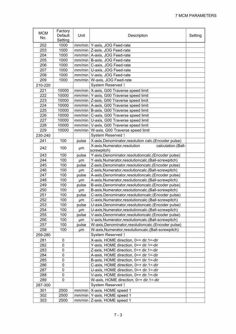
7 MCM PARAMETERS
7 - 3
MCM No.
Factory Default Setting
Unit Description Setting
202 1000 mm/min Y-axis, JOG Feed-rate 203 1000 mm/min Z-axis, JOG Feed-rate 204 1000 mm/min A-axis, JOG Feed-rate 205 1000 mm/min B-axis, JOG Feed-rate 206 1000 mm/min C-axis, JOG Feed-rate 207 1000 mm/min U-axis, JOG Feed-rate 208 1000 mm/min V-axis, JOG Feed-rate 209 1000 mm/min W-axis, JOG Feed-rate
210-220 System Reserved! 221 10000 mm/min X-axis, G00 Traverse speed limit 222 10000 mm/min Y-axis, G00 Traverse speed limit 223 10000 mm/min Z-axis, G00 Traverse speed limit 224 10000 mm/min A-axis, G00 Traverse speed limit 225 10000 mm/min B-axis, G00 Traverse speed limit 226 10000 mm/min C-axis, G00 Traverse speed limit 227 10000 mm/min U-axis, G00 Traverse speed limit 228 10000 mm/min V-axis, G00 Traverse speed limit 229 10000 mm/min W-axis, G00 Traverse speed limit
230-240 System Reserved! 241 100 pulse X-axis,Denominator,resolution calc.(Encoder pulse)
242 100 μm X-axis,Numerator,resolution calculation.(Ball-screwpitch)
243 100 pulse Y-axis,Denominator,resolutioncalc.(Encoder pulse) 244 100 μm Y-axis,Numerator,resolutioncalc.(Ball-screwpitch) 245 100 pulse Z-axis,Denominator,resolutioncalc.(Encoder pulse) 246 100 μm Z-axis,Numerator,resolutioncalc.(Ball-screwpitch) 247 100 pulse A-axis,Denominator,resolutioncalc.(Encoder pulse) 248 100 μm A-axis,Numerator,resolutioncalc.(Ball-screwpitch) 249 100 pulse B-axis,Denominator,resolutioncalc.(Encoder pulse) 250 100 μm B-axis,Numerator,resolutioncalc.(Ball-screwpitch) 251 100 pulse C-axis,Denominator,resolutioncalc.(Encoder pulse) 252 100 μm C-axis,Numerator,resolutioncalc.(Ball-screwpitch) 253 100 pulse U-axis,Denominator,resolutioncalc.(Encoder pulse) 254 100 μm U-axis,Numerator,resolutioncalc.(Ball-screwpitch) 255 100 pulse V-axis,Denominator,resolutioncalc.(Encoder pulse) 256 100 μm V-axis,Numerator,resolutioncalc.(Ball-screwpitch) 257 100 pulse W-axis,Denominator,resolutioncalc.(Encoder pulse) 258 100 μm W-axis,Numerator,resolutioncalc.(Ball-screwpitch)
259-280 System Reserved! 281 0 X-axis, HOME direction, 0=+ dir.1=-dir 282 0 Y-axis, HOME direction, 0=+ dir.1=-dir 283 0 Z-axis, HOME direction, 0=+ dir.1=-dir 284 0 A-axis, HOME direction, 0=+ dir.1=-dir 285 0 B-axis, HOME direction, 0=+ dir.1=-dir 286 0 C-axis, HOME direction, 0=+ dir.1=-dir 287 0 U-axis, HOME direction, 0=+ dir.1=-dir 288 0 V-axis, HOME direction, 0=+ dir.1=-dir 289 0 W-axis, HOME direction, 0=+ dir.1=-dir
287-300 System Reserved! 301 2500 mm/min X-axis, HOME speed 1 302 2500 mm/min Y-axis, HOME speed 1 303 2500 mm/min Z-axis, HOME speed 1

HUST CNC H4D-T MANUALl
7 - 4
MCM No.
Factory Default Setting
Unit Description Setting
304 2500 mm/min A-axis, HOME speed 1 305 2500 mm/min B-axis, HOME speed 1 306 2500 mm/min C-axis, HOME speed 1 207 2500 mm/min U-axis, HOME speed 1 308 2500 mm/min V-axis, HOME speed 1 309 2500 mm/min W-axis, HOME speed 1
310-320 System Reserved! 321 40 mm/min X-axis, Home grid speed during HOME execution 322 40 mm/min Y-axis, Home grid speed during HOME execution 323 40 mm/min Z-axis, Home grid speed during HOME execution 324 40 mm/min A-axis, Home grid speed during HOME execution 325 40 mm/min B-axis, Home grid speed during HOME execution 326 40 mm/min C-axis, Home grid speed during HOME execution 327 40 mm/min U-axis, Home grid speed during HOME execution 328 40 mm/min V-axis, Home grid speed during HOME execution 329 40 mm/min W-axis, Home grid speed during HOME execution
330-340 System Reserved! 341 0 0/1 X-axis,Home grid direction during HOME execution 342 0 0/1 Y-axis,Home grid direction during HOME execution 343 0 0/1 Z-axis,Home grid direction during HOME execution 344 0 0/1 A-axis,Home grid direction during HOME execution 345 0 0/1 B-axis,Home grid direction during HOME execution 346 0 0/1 C-axis,Home grid direction during HOME execution 347 0 0/1 U-axis,Home grid direction during HOME execution 348 0 0/1 V-axis,Home grid direction during HOME execution 349 0 0/1 W-axis,Home grid direction during HOME execution
350-360 System Reserved! 361 0 mm X –axis Home grid setting 362 0 mm Y-axis Home grid setting 363 0 mm Z-axis Home grid setting 364 0 mm A-axis Home grid setting 365 0 mm B-axis Home grid setting 366 0 mm C-axis Home grid setting 367 0 mm U-axis Home grid setting 368 0 mm V-axis Home grid setting 369 0 mm W-axis Home grid setting
370-380 System Reserved! 381 0 mm X-axis, HOME shift data 382 0 mm Y-axis, HOME shift data 383 0 mm Z-axis, HOME shift data 384 0 mm A-axis, HOME shift data 385 0 mm B-axis, HOME shift data 386 0 mm C-axis, HOME shift data 387 0 mm U-axis, HOME shift data 388 0 mm V-axis, HOME shift data 389 0 mm W-axis, HOME shift data
390-400 System Reserved! 401 10.000 mm X-axis,Setting the value of search servo grid 402 10.000 mm Y-axis,Setting the value of search servo grid 403 10.000 mm Z-axis,Setting the value of search servo grid 404 10.000 mm A-axis,Setting the value of search servo grid 405 10.000 mm B-axis,Setting the value of search servo grid

7 MCM PARAMETERS
7 - 5
MCM No.
Factory Default Setting
Unit Description Setting
406 10.000 mm C-axis,Setting the value of search servo grid 407 10.000 mm U-axis,Setting the value of search servo grid 408 10.000 mm V-axis,Setting the value of search servo grid 409 10.000 mm W-axis,Setting the value of search servo grid
410-420 0 System Reserved!
421 0 X-axis Origin switch (+ :N.O (normallyopen) node; -:N.C (normally closed) node)
422 0 Y-axis Origin switch (+ :N.O node; -:N.C node) 423 0 Z-axis Origin switch (+ :N.O node; - :N.C node) 424 0 A-axis Origin switch (+ :N.O node; - :N.C node) 425 0 B-axis Origin switch (+ :N.O node; - :N.C node) 426 0 C-axis Origin switch (+ :N.O node; - :N.C node) 427 0 U-axis Origin switch (+ :N.O node; - :N.C node) 428 0 V-axis Origin switch (+ :N.O node; - :N.C node) 429 0 W-axis Origin switch (+ :N.O node; - :N.C node)
430-440 System Reserved! 441 0 X-axis, Direction of motor rotation, 0=CW, 1=CCW 442 0 Y-axis, Direction of motor rotation, 0=CW, 1=CCW 443 0 Z-axis, Direction of motor rotation, 0=CW, 1=CCW 444 0 A-axis, Direction of motor rotation, 0=CW, 1=CCW 445 0 B-axis, Direction of motor rotation, 0=CW, 1=CCW 446 0 C-axis, Direction of motor rotation, 0=CW, 1=CCW 447 0 U-axis, Direction of motor rotation, 0=CW, 1=CCW 448 0 V-axis, Direction of motor rotation, 0=CW, 1=CCW 449 0 W-axis, Direction of motor rotation, 0=CW, 1=CCW
450-460 System Reserved! 461 4 X-axis,Encoder pulse multiplicationfactor,1,2,or 4 462 4 Y-axis,Encoder pulse multiplicationfactor,1,2,or 4 463 4 Z-axis,Encoder pulse multiplicationfactor,1,2,or 4 464 4 A-axis,Encoder pulse multiplicationfactor,1,2,or 4 465 4 B-axis,Encoder pulse multiplicationfactor,1,2,or 4 466 4 C-axis,Encoder pulse multiplicationfactor,1,2,or 4 467 4 U-axis,Encoder pulse multiplicationfactor,1,2,or 4 468 4 V-axis,Encoder pulse multiplicationfactor,1,2,or 4 469 4 W-axis,Encoder pulse multiplicationfactor,1,2,or 4
470-480 System Reserved!
481 5 X-axis impulse command width adjustment (4=625KPPS)
482 5 Y-axis impulse command width adjustment (4=625KPPS)
483 5 Z-axis impulse command width adjustment (4=625KPPS)
484 5 A-axis impulse command width adjustment (4=625KPPS)
485 5 B-axis impulse command width adjustment (4=625KPPS)
486 5 C-axis impulse command width adjustment (4=625KPPS)
487 5 U-axis impulse command width adjustment (4=625KPPS)
488 5 V-axis impulse command width adjustment (4=625KPPS)
489 5 W-axis impulse command width adjustment

HUST CNC H4D-T MANUALl
7 - 6
MCM No.
Factory Default Setting
Unit Description Setting
(4=625KPPS) 490-500 6 System Reserved!
501 0
Master/Slave mode, 0=CNC, 1=X-axis, 2=Y-axis 3=Z-axis,4=A-axis,5=B-axis,6=C-axis,7=U-axis, 8=V-axis, 9=w-axis, 256= non-stop mode in a single block
502 0 Accel/Decel mode,0=exponential,1=linear,2=”S” curve
503 0
Home command mode setting. BIT0 = 0 , X axis find Home grid available,
= 1 , no need to find.
BIT1 = 0 , Y axis find Home grid available, = 1 , no need to find.
BIT2 = 0 , Z axis find Home grid available, = 1 , no need to find.
BIT3 = 0 , A axis find Home grid available, = 1 , no need to find.
BIT4 = 0 , B axis find Home grid available, = 1 , no need to find.
BIT5 = 0 , C axis find Home grid available, = 1 , no need to find.
BIT6 = 0 , U axis find Home grid available, = 1 , no need to find.
BIT7 = 0 , V axis find Home grid available, = 1 , no need to find.
BIT8 = 0 , W axis find Home grid available, = 1 , no need to find.
504 100 msec G01 Linear accel./decel. Time, 10~1024 ms 505 100 msec Accel/Decel time when in G99 mode (mm/rev) 506 100 msec Time Setting for spindle acceleration 507 100 msec System Reserved! 508 0 Spindle encoder resolution (pulse/rev) 509 4096 pulse Max. spindle rpm at 10 volts
510 3000 rpm Spindle voltage command zero drift correction (open circuit)
511 0 v Spindle voltage command acce/dece slope correction (open circuit)
512 0 Spindle RPM correction (based on feedback from the encoder)
513 0 rpm Start number for program block number generation 514 0 Increment for program block number generation 515 0 Denominator of feed-rate when in MPG test mode 516 1 Numerator of feed-rate when in MPG test mode 517 1 MPG direction 518 0 Set Acceleration/Deceleration Time for MPG (4~512) 519 64 ms RS232 Baud rate, 38400, 19200 / EVEN /2 Bit
520 38400 Setting whether R000~R99 data in PLC are stored when power is cut off. 0=NO, 256=YES
521 0 Servo Error Counter 522 0 pulse Radius/Diameter Programming mode 523 0 0=Metric mode, 25400=inch mode mcm541=0,1 524 0 Error in Circular Cutting, ideal value=1
525 3 Pulse settings 0: pulse + direction 1: +/- pulse 2: A/B phase
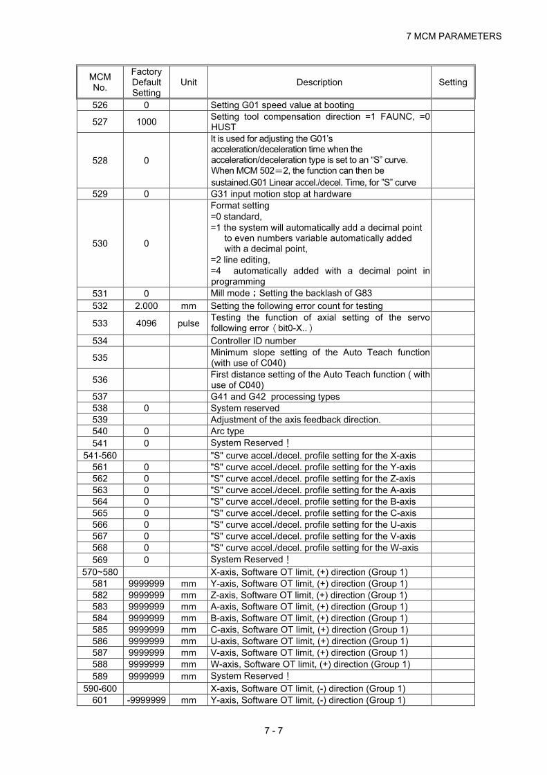
7 MCM PARAMETERS
7 - 7
MCM No.
Factory Default Setting
Unit Description Setting
526 0 Setting G01 speed value at booting
527 1000 Setting tool compensation direction =1 FAUNC, =0 HUST
528 0
It is used for adjusting the G01’s acceleration/deceleration time when the acceleration/deceleration type is set to an “S” curve. When MCM 502=2, the function can then be sustained.G01 Linear accel./decel. Time, for ”S” curve
529 0 G31 input motion stop at hardware
530 0
Format setting =0 standard, =1 the system will automatically add a decimal point
to even numbers variable automatically added with a decimal point,
=2 line editing, =4 automatically added with a decimal point in programming
531 0 Mill mode;Setting the backlash of G83 532 2.000 mm Setting the following error count for testing
533 4096 pulse Testing the function of axial setting of the servo following error(bit0-X..)
534 Controller ID number
535 Minimum slope setting of the Auto Teach function (with use of C040)
536 First distance setting of the Auto Teach function ( with use of C040)
537 G41 and G42 processing types 538 0 System reserved 539 Adjustment of the axis feedback direction. 540 0 Arc type 541 0 System Reserved!
541-560 "S" curve accel./decel. profile setting for the X-axis 561 0 "S" curve accel./decel. profile setting for the Y-axis 562 0 "S" curve accel./decel. profile setting for the Z-axis 563 0 "S" curve accel./decel. profile setting for the A-axis 564 0 "S" curve accel./decel. profile setting for the B-axis 565 0 "S" curve accel./decel. profile setting for the C-axis 566 0 "S" curve accel./decel. profile setting for the U-axis 567 0 "S" curve accel./decel. profile setting for the V-axis 568 0 "S" curve accel./decel. profile setting for the W-axis 569 0 System Reserved!
570~580 X-axis, Software OT limit, (+) direction (Group 1) 581 9999999 mm Y-axis, Software OT limit, (+) direction (Group 1) 582 9999999 mm Z-axis, Software OT limit, (+) direction (Group 1) 583 9999999 mm A-axis, Software OT limit, (+) direction (Group 1) 584 9999999 mm B-axis, Software OT limit, (+) direction (Group 1) 585 9999999 mm C-axis, Software OT limit, (+) direction (Group 1) 586 9999999 mm U-axis, Software OT limit, (+) direction (Group 1) 587 9999999 mm V-axis, Software OT limit, (+) direction (Group 1) 588 9999999 mm W-axis, Software OT limit, (+) direction (Group 1) 589 9999999 mm System Reserved!
590-600 X-axis, Software OT limit, (-) direction (Group 1) 601 -9999999 mm Y-axis, Software OT limit, (-) direction (Group 1)

HUST CNC H4D-T MANUALl
7 - 8
MCM No.
Factory Default Setting
Unit Description Setting
602 -9999999 mm Z-axis, Software OT limit, (-) direction (Group 1) 603 -9999999 mm A-axis, Software OT limit, (-) direction (Group 1) 604 -9999999 mm B-axis, Software OT limit, (-) direction (Group 1) 605 -9999999 mm C-axis, Software OT limit, (-) direction (Group 1) 606 -9999999 mm U-axis, Software OT limit, (-) direction (Group 1) 607 -9999999 mm V-axis, Software OT limit, (-) direction (Group 1) 608 -9999999 mm W-axis, Software OT limit, (-) direction (Group 1) 609 -9999999 mm System Reserved!
610-620 X-axis, Software OT limit, (+) direction (Group 2) 621 9999999 mm Y-axis, Software OT limit, (+) direction (Group 2) 622 9999999 mm Z-axis, Software OT limit, (+) direction (Group 2)
623 9999999A-axis, Software OT limit, (+) direction (Group 2)
624 9999999 mm B-axis, Software OT limit, (+) direction (Group 2) 625 9999999 mm C-axis, Software OT limit, (+) direction (Group 2) 626 9999999 mm U-axis, Software OT limit, (+) direction (Group 2) 627 9999999 mm V-axis, Software OT limit, (+) direction (Group 2) 628 9999999 mm W-axis, Software OT limit, (+) direction (Group 2) 629 9999999 mm System Reserved!
630-640 X-axis, Software OT limit, (-) direction (Group 2) 641 -9999999 mm Y-axis, Software OT limit, (-) direction (Group 2) 642 -9999999 mm Z-axis, Software OT limit, (-) direction (Group 2) 643 -9999999 mm A-axis, Software OT limit, (-) direction (Group 2) 644 -9999999 mm B-axis, Software OT limit, (-) direction (Group 2) 645 -9999999 mm C-axis, Software OT limit, (-) direction (Group 2) 646 -9999999 mm U-axis, Software OT limit, (-) direction (Group 2) 647 -9999999 mm V-axis, Software OT limit, (-) direction (Group 2) 648 -9999999 mm W-axis, Software OT limit, (-) direction (Group 2) 649 -9999999 mm System Reserved!
650-660 X-axis, Cycle clearing w/ M02, M30, M99 661 0 Y-axis, Cycle clearing w/ M02, M30, M99 662 0 Z-axis, Cycle clearing w/ M02, M30, M99 663 0 A-axis, Cycle clearing w/ M02, M30, M99 664 0 B-axis, Cycle clearing w/ M02, M30, M99 665 0 C-axis, Cycle clearing w/ M02, M30, M99 666 0 U-axis, Cycle clearing w/ M02, M30, M99 667 0 V-axis, Cycle clearing w/ M02, M30, M99 668 0 W-axis, Cycle clearing w/ M02, M30, M99 669 0 System Reserved!
670-680 0 X-axis,0=incrementalcoord.,1=absolute coordinate 681 1 Y-axis,0=incrementalcoord.,1=absolute coordinate 682 1 Z-axis,0=incrementalcoord.,1=absolute coordinate 683 1 A-axis,0=incrementalcoord.,1=absolute coordinate 684 1 B-axis,0=incrementalcoord.,1=absolute coordinate 685 1 C-axis,0=incrementalcoord.,1=absolute coordinate 686 1 U-axis,0=incrementalcoord.,1=absolute coordinate 687 1 V-axis,0=incrementalcoord.,1=absolute coordinate 688 1 W-axis,0=incrementalcoord.,1=absolute coordinate 689 1 System Reserved!
690-700 1 X-axis, Position gain, standard=64 701 64 pulse Y-axis, Position gain, standard=64 702 64 pulse Z-axis, Position gain, standard=64

7 MCM PARAMETERS
7 - 9
MCM No.
Factory Default Setting
Unit Description Setting
703 64 pulse A-axis, Position gain, standard=64 704 64 pulse B-axis, Position gain, standard=64 705 64 pulse C-axis, Position gain, standard=64 706 64 pulse U-axis, Position gain, standard=64 707 64 pulse V-axis, Position gain, standard=64 708 64 pulse W-axis, Position gain, standard=64 709 64 pulse System Reserved!
710-720 64 pulse X-axis,Break-over point for position gain, std=10 721 10 pulse Y-axis,Break-over point for position gain, std=10 722 10 pulse Z-axis,Break-over point for position gain, std=10 723 10 pulse A-axis,Break-over point for position gain, std=10 724 10 pulse B-axis,Break-over point for position gain, std=10 725 10 pulse C-axis,Break-over point for position gain, std=10 726 10 pulse U-axis,Break-over point for position gain, std=10 727 10 pulse V-axis,Break-over point for position gain, std=10 728 10 pulse W-axis,Break-over point for position gain, std=10 729 10 pulse System Reserved!
727-740 10 pulse X-axis, Denominator, MPG resolution calc. 741 100 X-axis, Numerator, MPG resolution calc. 742 100 Y-axis, Denominator, MPG resolution calc. 743 100 Y-axis, Numerator, MPG resolution calc. 744 100 Z-axis, Denominator, MPG resolution calc. 745 100 Z-axis, Numerator, MPG resolution calc. 746 100 A-axis, Denominator, MPG resolution calc. 747 100 A-axis, Numerator, MPG resolution calc. 748 100 B-axis, Denominator, MPG resolution calc. 749 100 B-axis, Numerator, MPG resolution calc. 750 100 C-axis, Denominator, MPG resolution calc. 751 100 C-axis, Numerator, MPG resolution calc. 752 100 U-axis, Denominator, MPG resolution calc. 753 100 U-axis, Numerator, MPG resolution calc. 754 100 V-axis, Denominator, MPG resolution calc. 755 100 V-axis, Numerator, MPG resolution calc. 756 100 W-axis, Denominator, MPG resolution calc. 757 100 W-axis, Numerator, MPG resolution calc. 758 100 System Reserved!
760-780 Set X-axis as Rotating (1) / Linear axis (0) 781 0 Set Y-axis as Rotating (1) / Linear axis (0) 782 0 Set Z-axis as Rotating (1) / Linear axis (0) 783 0 Set A-axis as Rotating (1) / Linear axis (0) 784 0 Set B-axis as Rotating (1) / Linear axis (0) 785 0 Set C-axis as Rotating (1) / Linear axis (0) 786 0 Set U-axis as Rotating (1) / Linear axis (0) 787 0 Set V-axis as Rotating (1) / Linear axis (0) 788 0 Set W-axis as Rotating (1) / Linear axis (0) 789 0 System Reserved!
790-800 Distance of S bit sent before the X-axis reaches in position. (S176)
801 0.000 mm Distance of S bit sent before the Y-axis reaches in position. (S177)
802 0.000 mm Distance of S bit sent before the Z-axis reaches in position. (S178)

HUST CNC H4D-T MANUALl
7 - 10
MCM No.
Factory Default Setting
Unit Description Setting
803 0.000 mm Distance of S bit sent before the A-axis reaches in position. (S179)
804 0.000 mm Distance of S bit sent before the B-axis reaches in position. (S180)
805 0.000 mm Distance of S bit sent before the C-axis reaches in position. (S181)
806 0.000 mm Distance of S bit sent before the U-axis reaches in position. (S182)
807 0.000 mm Distance of S bit sent before the V-axis reaches in position. (S183)
808 0.000 mm Distance of S bit sent before the W-axis reaches in position. (S184)
809 0.000 mm System Reserved! 810-820 Set Acceleration/Deceleration Time for X-axis
821 0 msec Set Acceleration/Deceleration Time for Y-axis 822 0 msec Set Acceleration/Deceleration Time for Z-axis 823 0 msec Set Acceleration/Deceleration Time for A-axis 824 0 msec Set Acceleration/Deceleration Time for B-axis 825 0 msec Set Acceleration/Deceleration Time for C-axis 826 0 msec Set Acceleration/Deceleration Time for U-axis 827 0 msec Set Acceleration/Deceleration Time for V-axis 828 0 msec Set Acceleration/Deceleration Time for W-axis 829 0 msec System Reserved!
830-840 X-axis allowable compensation of back screw pitch 841 0 Y-axis allowable compensation of back screw pitch 842 0 Z-axis allowable compensation of back screw pitch 843 0 A-axis allowable compensation of back screw pitch 844 0 B-axis allowable compensation of back screw pitch 845 0 C-axis allowable compensation of back screw pitch 846 0 U-axis allowable compensation of back screw pitch 847 0 V-axis allowable compensation of back screw pitch 848 0 W-axis allowable compensation of back screw pitch 849 0 System Reserved!
847-850 0 X-axis length compensation of back screw pitch 851 20000 mm Y-axis length compensation of back screw pitch 852 20000 mm Z-axis length compensation of back screw pitch 853 20000 mm A-axis length compensation of back screw pitch 854 20000 mm B-axis length compensation of back screw pitch 855 20000 mm C-axis length compensation of back screw pitch 856 20000 mm System Reserved!
857~860 X-axis,Pitch error compensation of each segment. 861-940 0 Y-axis,Pitch error compensation of each segment.
941-1020 0 Z-axis,Pitch error compensation of each segment. 1021-1100
0 A-axis,Pitch error compensation of each segment.
1101-1180
0 B-axis,Pitch error compensation of each segment.
1181-1260
0 C-axis,Pitch error compensation of each segment.
1261-1340
0 Tool #1 radius compensation
1341 0 mm X-axis, Tool #1 offset compensation 1342 0 mm Y-axis, Tool #1 offset compensation

7 MCM PARAMETERS
7 - 11
MCM No.
Factory Default Setting
Unit Description Setting
1343 0 mm Z-axis, Tool #1 offset compensation 1344 0 mm A-axis, Tool #1 offset compensation 1345 0 mm B-axis, Tool #1 offset compensation 1346 0 mm C-axis, Tool #1 offset compensation 1347 0 mm Tool #2 radius compensation 1348 0 mm X-axis, Tool #2 offset compensation 1349 0 mm Y-axis, Tool #2 offset compensation 1350 0 mm Z-axis, Tool #2 offset compensation 1351 0 mm A-axis, Tool #2 offset compensation 1352 0 mm B-axis, Tool #2 offset compensation 1353 0 mm C-axis, Tool #2 offset compensation 1354 0 mm Tool #3 radius compensation 1355 0 mm X-axis, Tool #3 offset compensation 1356 0 mm Y-axis, Tool #3 offset compensation 1357 0 mm Z-axis, Tool #3 offset compensation 1358 0 mm A-axis, Tool #3 offset compensation 1359 0 mm B-axis, Tool #3 offset compensation 1360 0 mm C-axis, Tool #3 offset compensation 1361 0 mm Tool #4 radius compensation 1362 0 mm X-axis, Tool #4 offset compensation 1363 0 mm Y-axis, Tool #4 offset compensation 1364 0 mm Z-axis, Tool #4 offset compensation 1365 0 mm A-axis, Tool #4 offset compensation 1366 0 mm B-axis, Tool #4 offset compensation 1367 0 mm C-axis, Tool #4 offset compensation 1368 0 mm Tool #5 radius compensation 1369 0 mm X-axis, Tool #5 offset compensation 1370 0 mm Y-axis, Tool #5 offset compensation 1371 0 mm Z-axis, Tool #5 offset compensation 1372 0 mm A-axis, Tool #5 offset compensation 1373 0 mm B-axis, Tool #5 offset compensation 1374 0 mm C-axis, Tool #5 offset compensation 1375 0 mm Tool #6 radius compensation 1376 0 mm X-axis, Tool #6 offset compensation 1377 0 mm Y-axis, Tool #6 offset compensation 1378 0 mm Z-axis, Tool #6 offset compensation 1379 0 mm A-axis, Tool #6 offset compensation 1380 0 mm B-axis, Tool #6 offset compensation 1381 0 mm C-axis, Tool #6 offset compensation 1382 0 mm Tool #7 radius compensation 1383 0 mm X-axis, Tool #7 offset compensation 1384 0 mm Y-axis, Tool #7 offset compensation 1385 0 mm Z-axis, Tool #7 offset compensation 1386 0 mm A-axis, Tool #7 offset compensation 1387 0 mm B-axis, Tool #7 offset compensation 1388 0 mm C-axis, Tool #7 offset compensation 1389 0 mm Tool #8 radius compensation 1390 0 mm X-axis, Tool #8 offset compensation 1391 0 mm Y-axis, Tool #8 offset compensation 1392 0 mm Z-axis, Tool #8 offset compensation 1393 0 mm A-axis, Tool #8 offset compensation 1394 0 mm B-axis, Tool #8 offset compensation 1395 0 mm C-axis, Tool #8 offset compensation

HUST CNC H4D-T MANUALl
7 - 12
MCM No.
Factory Default Setting
Unit Description Setting
1396 0 mm Tool #9 radius compensation 1397 0 mm X-axis, Tool #9 offset compensation 1398 0 mm Y-axis, Tool #9 offset compensation 1399 0 mm Z-axis, Tool #9 offset compensation 1400 0 mm A-axis, Tool #9 offset compensation 1401 0 mm B-axis, Tool #9 offset compensation 1402 0 mm C-axis, Tool #9 offset compensation 1403 0 mm Tool #10 radius compensation 1404 0 mm X-axis, Tool #10 offset compensation 1405 0 mm Y-axis, Tool #10 offset compensation 1406 0 mm Z-axis, Tool #10 offset compensation 1407 0 mm A-axis, Tool #10 offset compensation 1408 0 mm B-axis, Tool #10 offset compensation 1409 0 mm C-axis, Tool #10 offset compensation 1410 0 mm Tool #11 radius compensation 1411 0 mm X-axis, Tool #11 offset compensation 1412 0 mm Y-axis, Tool #11 offset compensation 1413 0 mm Z-axis, Tool #11 offset compensation 1414 0 mm A-axis, Tool #11 offset compensation 1415 0 mm B-axis, Tool #11 offset compensation 1416 0 mm C-axis, Tool #11 offset compensation 1417 0 mm Tool #12 radius compensation 1418 0 mm X-axis, Tool #12 offset compensation 1419 0 mm Y-axis, Tool #12 offset compensation 1420 0 mm Z-axis, Tool #12 offset compensation 1421 0 mm A-axis, Tool #12 offset compensation 1422 0 mm B-axis, Tool #12 offset compensation 1423 0 mm C-axis, Tool #12 offset compensation 1424 0 mm Tool #13 radius compensation 1425 0 mm X-axis, Tool #13 offset compensation 1426 0 mm Y-axis, Tool #13 offset compensation 1427 0 mm Z-axis, Tool #13 offset compensation 1428 0 mm A-axis, Tool #13 offset compensation 1429 0 mm B-axis, Tool #13 offset compensation 1430 0 mm C-axis, Tool #13 offset compensation 1431 0 mm Tool #14 radius compensation 1432 0 mm X-axis, Tool #14 offset compensation 1433 0 mm Y-axis, Tool #14 offset compensation 1434 0 mm Z-axis, Tool #14 offset compensation 1435 0 mm A-axis, Tool #14 offset compensation 1436 0 mm B-axis, Tool #14 offset compensation 1437 0 mm C-axis, Tool #14 offset compensation 1438 0 mm Tool # radius compensation 1439 0 mm X-axis, Tool #15 offset compensation 1440 0 mm Y-axis, Tool #15 offset compensation 1441 0 mm Z-axis, Tool #15 offset compensation 1442 0 mm A-axis, Tool #15 offset compensation 1443 0 mm B-axis, Tool #15 offset compensation 1444 0 mm C-axis, Tool #15 offset compensation 1445 0 mm Tool #16 radius compensation 1446 0 mm X-axis, Tool #16 offset compensation 1447 0 mm Y-axis, Tool #16 offset compensation 1448 0 mm Z-axis, Tool #16 offset compensation

7 MCM PARAMETERS
7 - 13
MCM No.
Factory Default Setting
Unit Description Setting
1449 0 mm A-axis, Tool #16 offset compensation 1450 0 mm B-axis, Tool #16 offset compensation 1451 0 mm C-axis, Tool #16 offset compensation 1452 0 mm Tool #17 radius compensation 1453 0 mm X-axis, Tool #17 offset compensation 1454 0 mm Y-axis, Tool #17 offset compensation 1455 0 mm Z-axis, Tool #17 offset compensation 1456 0 mm A-axis, Tool #17 offset compensation 1457 0 mm B-axis, Tool #17 offset compensation 1458 0 mm C-axis, Tool #17 offset compensation 1459 0 mm Tool #18 radius compensation 1460 0 mm X-axis, Tool #18 offset compensation 1461 0 mm Y-axis, Tool #18 offset compensation 1462 0 mm Z-axis, Tool #18 offset compensation 1463 0 mm A-axis, Tool #18 offset compensation 1464 0 mm B-axis, Tool #18 offset compensation 1465 0 mm C-axis, Tool #18 offset compensation 1466 0 mm Tool #19 radius compensation 1467 0 mm X-axis, Tool #19 offset compensation 1468 0 mm Y-axis, Tool #19 offset compensation 1469 0 mm Z-axis, Tool #19 offset compensation 1470 0 mm A-axis, Tool #19 offset compensation 1471 0 mm B-axis, Tool #19 offset compensation 1472 0 mm C-axis, Tool #19 offset compensation 1473 0 mm Tool #20 radius compensation 1474 0 mm X-axis, Tool #20 offset compensation 1475 0 mm Y-axis, Tool #20 offset compensation 1476 0 mm Z-axis, Tool #20 offset compensation 1477 0 mm A-axis, Tool #20 offset compensation 1478 0 mm B-axis, Tool #20 offset compensation 1479 0 mm C-axis, Tool #20 offset compensation 1480 0 mm Tool #21 radius compensation 1481 0 mm X-axis, Tool #21 offset compensation 1482 0 mm Y-axis, Tool #21 offset compensation 1483 0 mm Z-axis, Tool #21 offset compensation 1484 0 mm A-axis, Tool #21 offset compensation 1485 0 mm B-axis, Tool #21 offset compensation 1486 0 mm C-axis, Tool #21 offset compensation 1487 0 mm Tool #22 radius compensation 1488 0 mm X-axis, Tool #22 offset compensation 1489 0 mm Y-axis, Tool #22 offset compensation 1490 0 mm Z-axis, Tool #22 offset compensation 1491 0 mm A-axis, Tool #22 offset compensation 1492 0 mm B-axis, Tool #22 offset compensation 1493 0 mm C-axis, Tool #22 offset compensation 1494 0 mm Tool #23 radius compensation 1495 0 mm X-axis, Tool #23 offset compensation 1496 0 mm Y-axis, Tool #23 offset compensation 1497 0 mm Z-axis, Tool #23 offset compensation 1498 0 mm A-axis, Tool #23 offset compensation 1499 0 mm B-axis, Tool #23 offset compensation 1500 0 mm C-axis, Tool #23 offset compensation 1501 0 mm Tool #24 radius compensation

HUST CNC H4D-T MANUALl
7 - 14
MCM No.
Factory Default Setting
Unit Description Setting
1502 0 mm X-axis, Tool #24 offset compensation 1503 0 mm Y-axis, Tool #24 offset compensation 1504 0 mm Z-axis, Tool #24 offset compensation 1505 0 mm A-axis, Tool #24 offset compensation 1506 0 mm B-axis, Tool #24 offset compensation 1507 0 mm C-axis, Tool #24 offset compensation 1508 0 mm Tool #25 radius compensation 1509 0 mm X-axis, Tool #25 offset compensation 1510 0 mm Y-axis, Tool #25 offset compensation 1511 0 mm Z-axis, Tool #25 offset compensation 1512 0 mm A-axis, Tool #25 offset compensation 1513 0 mm B-axis, Tool #25 offset compensation 1514 0 mm C-axis, Tool #25 offset compensation 1515 0 mm Tool #26 radius compensation 1516 0 mm X-axis, Tool #26 offset compensation 1517 0 mm Y-axis, Tool #26 offset compensation 1518 0 mm Z-axis, Tool #26 offset compensation 1519 0 mm A-axis, Tool #26 offset compensation 1520 0 mm B-axis, Tool #26 offset compensation 1521 0 mm C-axis, Tool #26 offset compensation 1522 0 mm Tool #27 radius compensation 1523 0 mm X-axis, Tool #27 offset compensation 1524 0 mm Y-axis, Tool #27 offset compensation 1525 0 mm Z-axis, Tool #27 offset compensation 1526 0 mm A-axis, Tool #27 offset compensation 1527 0 mm B-axis, Tool #27 offset compensation 1528 0 mm C-axis, Tool #27 offset compensation 1529 0 mm Tool #28 radius compensation 1530 0 mm X-axis, Tool #28 offset compensation 1531 0 mm Y-axis, Tool #28 offset compensation 1532 0 mm Z-axis, Tool #28 offset compensation 1533 0 mm A-axis, Tool #28 offset compensation 1534 0 mm B-axis, Tool #28 offset compensation 1535 0 mm C-axis, Tool #28offset compensation 1536 0 mm Tool #29 radius compensation 1537 0 mm X-axis, Tool #29 offset compensation 1538 0 mm Y-axis, Tool #29 offset compensation 1539 0 mm Z-axis, Tool #29 offset compensation 1540 0 mm A-axis, Tool #29 offset compensation 1541 0 mm B-axis, Tool #29 offset compensation 1542 0 mm C-axis, Tool #29 offset compensation 1543 0 mm Tool #30 radius compensation 1544 0 mm X-axis, Tool #30 offset compensation
1545 0 Y-axis, Tool #30 offset compensation
1546 0 mm Z-axis, Tool #30 offset compensation 1547 0 mm A-axis, Tool #30 offset compensation 1548 0 mm B-axis, Tool #30 offset compensation 1549 0 mm C-axis, Tool #30 offset compensation 1550 0 mm Tool 31# radius compensation 1551 0 mm X-axis, Tool #31 offset compensation 1552 0 mm Y-axis, Tool #31 offset compensation 1553 0 mm Z-axis, Tool #31 offset compensation

7 MCM PARAMETERS
7 - 15
MCM No.
Factory Default Setting
Unit Description Setting
1554 0 mm A-axis, Tool #31 offset compensation 1555 0 mm B-axis, Tool #31 offset compensation 1556 0 mm C-axis, Tool #31 offset compensation 1557 0 mm Tool #32 radius compensation 1558 0 mm X-axis, Tool #32 offset compensation 1559 0 mm Y-axis, Tool #32 offset compensation 1560 0 mm Z-axis, Tool #32 offset compensation 1561 0 mm A-axis, Tool #32 offset compensation 1562 0 mm B-axis, Tool #32 offset compensation 1563 0 mm C-axis, Tool #32 offset compensation 1564 0 mm Tool #33radius compensation 1565 0 mm X-axis, Tool #33 offset compensation 1566 0 mm Y-axis, Tool #33 offset compensation 1567 0 mm Z-axis, Tool #33 offset compensation 1568 0 mm A-axis, Tool #33 offset compensation 1569 0 mm B-axis, Tool #33 offset compensation 1570 0 mm C-axis, Tool #33 offset compensation 1571 0 mm Tool #34 radius compensation 1572 0 mm X-axis, Tool #34 offset compensation 1573 0 mm Y-axis, Tool #34 offset compensation 1574 0 mm Z-axis, Tool #34 offset compensation 1575 0 mm A-axis, Tool #34 offset compensation 1576 0 mm B-axis, Tool #34 offset compensation 1577 0 mm C-axis, Tool #34 offset compensation 1578 0 mm Tool #35 radius compensation 1579 0 mm X-axis, Tool #35 offset compensation 1580 0 mm Y-axis, Tool #35 offset compensation 1581 0 mm Z-axis, Tool #35 offset compensation 1582 0 mm A-axis, Tool #35 offset compensation 1583 0 mm B-axis, Tool #35 offset compensation 1584 0 mm C-axis, Tool #35 offset compensation 1585 0 mm Tool #36 radius compensation 1586 0 mm X-axis, Tool #36 offset compensation 1587 0 mm Y-axis, Tool #36 offset compensation 1588 0 mm Z-axis, Tool #36 offset compensation 1589 0 mm A-axis, Tool #36 offset compensation 1590 0 mm B-axis, Tool #36 offset compensation 1591 0 mm C-axis, Tool #36 offset compensation 1592 0 mm Tool #37 radius compensation 1593 0 mm X-axis, Tool #37 offset compensation 1594 0 mm Y-axis, Tool #37 offset compensation 1595 0 mm Z-axis, Tool #37 offset compensation 1596 0 mm A-axis, Tool #37 offset compensation 1597 0 mm B-axis, Tool #37 offset compensation 1598 0 mm C-axis, Tool #37 offset compensation 1599 0 mm Tool #38 radius compensation 1600 0 mm X-axis, Tool #38 offset compensation 1601 0 mm Y-axis, Tool #38 offset compensation 1602 0 mm Z-axis, Tool #38 offset compensation 1603 0 mm A-axis, Tool #38 offset compensation 1604 0 mm B-axis, Tool #38 offset compensation 1605 0 mm C-axis, Tool #38 offset compensation 1606 0 mm Tool #39 radius compensation

HUST CNC H4D-T MANUALl
7 - 16
MCM No.
Factory Default Setting
Unit Description Setting
1607 0 mm X-axis, Tool #39 offset compensation 1608 0 mm Y-axis, Tool #39 offset compensation 1609 0 mm Z-axis, Tool #39 offset compensation 1610 0 mm A-axis, Tool #39 offset compensation 1611 0 mm B-axis, Tool #39 offset compensation 1612 0 mm C-axis, Tool #39 offset compensation 1613 0 mm Tool #40 radius compensation 1614 0 mm X-axis, Tool #40 offset compensation 1615 0 mm Y-axis, Tool #40 offset compensation 1616 0 mm Z-axis, Tool #40 offset compensation 1617 0 mm A-axis, Tool #40 offset compensation 1618 0 mm B-axis, Tool #40 offset compensation 1619 0 mm C-axis, Tool #40 offset compensation 1620 0 mm Tool #1 radius wear compensation 1621 0 mm X-axis, Tool #1 wear compensation 1622 0 mm Y-axis, Tool #1 wear compensation 1623 0 mm Z-axis, Tool #1 wear compensation 1624 0 mm A-axis, Tool #1 wear compensation 1625 0 mm B-axis, Tool #1 wear compensation 1626 0 mm C-axis, Tool #1 wear compensation 1627 0 mm Tool #2 radius wear compensation 1628 0 mm X-axis, Tool #2 wear compensation 1629 0 mm Y-axis, Tool #2 wear compensation 1630 0 mm Y-axis, Tool #2 wear compensation 1631 0 mm A-axis, Tool #2 wear compensation 1632 0 mm B-axis, Tool #2 wear compensation 1633 0 mm C-axis, Tool #2 wear compensation 1634 0 mm Tool #3 radius wear compensation 1635 0 mm X-axis, Tool #3 wear compensation 1636 0 mm Y-axis, Tool #3 wear compensation 1637 0 mm Z-axis, Tool #3 wear compensation 1638 0 mm A-axis, Tool #3 wear compensation 1639 0 mm B-axis, Tool #3 wear compensation 1640 0 mm C-axis, Tool #3 wear compensation 1641 0 mm Tool #4 radius wear compensation 1642 0 mm X-axis, Tool #4 wear compensation 1643 0 mm Y-axis, Tool #4 wear compensation 1644 0 mm Z-axis, Tool #4 wear compensation 1645 0 mm A-axis, Tool #4 wear compensation 1646 0 mm B-axis, Tool #4 wear compensation 1647 0 mm C-axis, Tool #4 wear compensation 1648 0 mm Tool #5 radius wear compensation 1649 0 mm X-axis, Tool #5 wear compensation 1650 0 mm Y-axis, Tool #5 wear compensation 1651 0 mm Z-axis, Tool #5 wear compensation 1652 0 mm A-axis, Tool #5 wear compensation 1653 0 mm B-axis, Tool #5 wear compensation 1654 0 mm C-axis, Tool #5 wear compensation 1655 0 mm Tool #6 radius wear compensation 1656 0 mm X-axis, Tool #6 wear compensation 1657 0 mm Y-axis, Tool #6 wear compensation 1658 0 mm Z-axis, Tool #6 wear compensation 1659 0 mm A-axis, Tool #6 wear compensation

7 MCM PARAMETERS
7 - 17
MCM No.
Factory Default Setting
Unit Description Setting
1660 0 mm B-axis, Tool #6 wear compensation 1661 0 mm C-axis, Tool #6 wear compensation 1662 0 mm Tool #7 radius wear compensation 1663 0 mm X-axis, Tool #7 wear compensation 1664 0 mm Y-axis, Tool #7 wear compensation 1665 0 mm Z-axis, Tool #7 wear compensation 1666 0 mm A-axis, Tool #7 wear compensation 1667 0 mm B-axis, Tool #7 wear compensation 1668 0 mm C-axis, Tool #7 wear compensation 1669 0 mm Tool #8 radius wear compensation 1670 0 mm X-axis, Tool #8 wear compensation 1671 0 mm Y-axis, Tool #8 wear compensation 1672 0 mm Z-axis, Tool #8 wear compensation 1673 0 mm A-axis, Tool #8 wear compensation 1674 0 mm B-axis, Tool #8 wear compensation 1675 0 mm C-axis, Tool #8 wear compensation 1676 0 mm Tool #9 radius wear compensation 1677 0 mm X-axis, Tool #9 wear compensation 1678 0 mm Y-axis, Tool #9 wear compensation 1679 0 mm Z-axis, Tool #9 wear compensation 1680 0 mm A-axis, Tool #9 wear compensation 1681 0 mm B-axis, Tool #9 wear compensation 1682 0 mm C-axis, Tool #9 wear compensation 1683 0 mm Tool #10 radius wear compensation 1684 0 mm X-axis, Tool #10 wear compensation 1685 0 mm Y-axis, Tool #10 wear compensation 1686 0 mm Z-axis, Tool #10 wear compensation 1687 0 mm A-axis, Tool #10 wear compensation 1688 0 mm B-axis, Tool #10 wear compensation 1689 0 mm C-axis, Tool #10 wear compensation 1690 0 mm Tool #11 radius wear compensation 1691 0 mm X-axis, Tool #11 wear compensation 1692 0 mm Y-axis, Tool #11 wear compensation 1693 0 mm Z-axis, Tool #11 wear compensation 1694 0 mm A-axis, Tool #1 wear compensation 1695 0 mm B-axis, Tool #11 wear compensation 1696 0 mm C-axis, Tool #11 wear compensation 1697 0 mm Tool #12 radius wear compensation 1698 0 mm X-axis, Tool #12 wear compensation 1699 0 mm Y-axis, Tool #12 wear compensation 1700 0 mm Z-axis, Tool #12 wear compensation 1701 0 mm A-axis, Tool #12 wear compensation 1702 0 mm B-axis, Tool #12 wear compensation 1703 0 mm C-axis, Tool #12 wear compensation 1704 0 mm Tool #13 radius wear compensation 1705 0 mm X-axis, Tool #13 wear compensation 1706 0 mm Y-axis, Tool #13 wear compensation 1707 0 mm Z-axis, Tool #13 wear compensation 1708 0 mm A-axis, Tool #13 wear compensation 1709 0 mm B-axis, Tool #13 wear compensation 1710 0 mm C-axis, Tool #13 wear compensation 1711 0 mm Tool #14 radius wear compensation 1712 0 mm X-axis, Tool #14 wear compensation

HUST CNC H4D-T MANUALl
7 - 18
MCM No.
Factory Default Setting
Unit Description Setting
1713 0 mm Y-axis, Tool #14 wear compensation 1714 0 mm Z-axis, Tool #14 wear compensation 1715 0 mm A-axis, Tool #14 wear compensation 1716 0 mm B-axis, Tool #14 wear compensation 1717 0 mm C-axis, Tool #14 wear compensation 1718 0 mm Tool #15 radius wear compensation 1719 0 mm X-axis, Tool #15 wear compensation 1720 0 mm Y-axis, Tool #15 wear compensation 1721 0 mm Z-axis, Tool #15 wear compensation 1722 0 mm A-axis, Tool #15 wear compensation 1723 0 mm B-axis, Tool #15 wear compensation 1724 0 mm C-axis, Tool #15wear compensation 1725 0 mm Tool #16 radius wear compensation 1726 0 mm X-axis, Tool #16 wear compensation 1727 0 mm Y-axis, Tool #16 wear compensation 1728 0 mm Z-axis, Tool #16 wear compensation 1729 0 mm A-axis, Tool #16 wear compensation 1730 0 mm B-axis, Tool #16 wear compensation 1731 0 mm C-axis, Tool #16 wear compensation 1732 0 mm Tool #17 radius wear compensation 1733 0 mm X-axis, Tool #17 wear compensation 1734 0 mm Y-axis, Tool #17 wear compensation 1735 0 mm Z-axis, Tool #17 wear compensation 1736 0 mm A-axis, Tool #17 wear compensation 1737 0 mm B-axis, Tool #17 wear compensation 1738 0 mm C-axis, Tool #17 wear compensation 1739 0 mm Tool #18 radius wear compensation 1740 0 mm X-axis, Tool #18 wear compensation 1741 0 mm Y-axis, Tool #18 wear compensation 1742 0 mm Z-axis, Tool #18 wear compensation 1743 0 mm A-axis, Tool #18 wear compensation 1744 0 mm B-axis, Tool #18 wear compensation 1745 0 mm C-axis, Tool #18 wear compensation 1746 0 mm Tool #19 radius wear compensation 1747 0 mm X-axis, Tool #19 wear compensation 1748 0 mm Y-axis, Tool #19 wear compensation 1749 0 mm Z-axis, Tool #19 wear compensation 1750 0 mm A-axis, Tool #19 wear compensation 1751 0 mm B-axis, Tool #19 wear compensation 1752 0 mm C-axis, Tool #19wear compensation 1753 0 mm Tool #20 radius wear compensation 1754 0 mm X-axis, Tool #20 wear compensation 1755 0 mm Y-axis, Tool #20 wear compensation 1756 0 mm Z-axis, Tool #20 wear compensation 1757 0 mm A-axis, Tool #20 wear compensation 1758 0 mm B-axis, Tool #20 wear compensation 1759 0 mm C-axis, Tool #20 wear compensation 1760 0 mm Tool #21 radius wear compensation 1761 0 mm X-axis, Tool #21 wear compensation 1762 0 mm Y-axis, Tool #21 wear compensation 1763 0 mm Z-axis, Tool #21 wear compensation 1764 0 mm A-axis, Tool #21 wear compensation 1765 0 mm B-axis, Tool #21 wear compensation
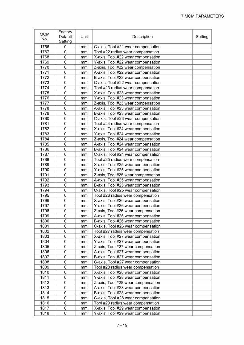
7 MCM PARAMETERS
7 - 19
MCM No.
Factory Default Setting
Unit Description Setting
1766 0 mm C-axis, Tool #21 wear compensation 1767 0 mm Tool #22 radius wear compensation 1768 0 mm X-axis, Tool #22 wear compensation 1769 0 mm Y-axis, Tool #22 wear compensation 1770 0 mm Z-axis, Tool #22 wear compensation 1771 0 mm A-axis, Tool #22 wear compensation 1772 0 mm B-axis, Tool #22 wear compensation 1773 0 mm C-axis, Tool #22 wear compensation 1774 0 mm Tool #23 radius wear compensation 1775 0 mm X-axis, Tool #23 wear compensation 1776 0 mm Y-axis, Tool #23 wear compensation 1777 0 mm Z-axis, Tool #23 wear compensation 1778 0 mm A-axis, Tool #23 wear compensation 1779 0 mm B-axis, Tool #23 wear compensation 1780 0 mm C-axis, Tool #23 wear compensation 1781 0 mm Tool #24 radius wear compensation 1782 0 mm X-axis, Tool #24 wear compensation 1783 0 mm Y-axis, Tool #24 wear compensation 1784 0 mm Z-axis, Tool #24 wear compensation 1785 0 mm A-axis, Tool #24 wear compensation 1786 0 mm B-axis, Tool #24 wear compensation 1787 0 mm C-axis, Tool #24 wear compensation 1788 0 mm Tool #25 radius wear compensation 1789 0 mm X-axis, Tool #25 wear compensation 1790 0 mm Y-axis, Tool #25 wear compensation 1791 0 mm Z-axis, Tool #25 wear compensation 1792 0 mm A-axis, Tool #25 wear compensation 1793 0 mm B-axis, Tool #25 wear compensation 1794 0 mm C-axis, Tool #25 wear compensation 1795 0 mm Tool #26 radius wear compensation 1796 0 mm X-axis, Tool #26 wear compensation 1797 0 mm Y-axis, Tool #26 wear compensation 1798 0 mm Z-axis, Tool #26 wear compensation 1799 0 mm A-axis, Tool #26 wear compensation 1800 0 mm B-axis, Tool #26 wear compensation 1801 0 mm C-axis, Tool #26 wear compensation 1802 0 mm Tool #27 radius wear compensation 1803 0 mm X-axis, Tool #27 wear compensation 1804 0 mm Y-axis, Tool #27 wear compensation 1805 0 mm Z-axis, Tool #27 wear compensation 1806 0 mm A-axis, Tool #27 wear compensation 1807 0 mm B-axis, Tool #27 wear compensation 1808 0 mm C-axis, Tool #27 wear compensation 1809 0 mm Tool #28 radius wear compensation 1810 0 mm X-axis, Tool #28 wear compensation 1811 0 mm Y-axis, Tool #28 wear compensation 1812 0 mm Z-axis, Tool #28 wear compensation 1813 0 mm A-axis, Tool #28 wear compensation 1814 0 mm B-axis, Tool #28 wear compensation 1815 0 mm C-axis, Tool #28 wear compensation 1816 0 mm Tool #29 radius wear compensation 1817 0 mm X-axis, Tool #29 wear compensation 1818 0 mm Y-axis, Tool #29 wear compensation

HUST CNC H4D-T MANUALl
7 - 20
MCM No.
Factory Default Setting
Unit Description Setting
1819 0 mm Z-axis, Tool #29 wear compensation 1820 0 mm A-axis, Tool #29 wear compensation 1821 0 mm B-axis, Tool #29 wear compensation 1822 0 mm C-axis, Tool #29 wear compensation 1823 0 mm Tool #30 radius wear compensation 1824 0 mm X-axis, Tool #30 wear compensation 1825 0 mm Y-axis, Tool #30 wear compensation 1826 0 mm Z-axis, Tool #30 wear compensation 1827 0 mm A-axis, Tool #30 wear compensation 1828 0 mm B-axis, Tool #30 wear compensation 1829 0 mm C-axis, Tool #30 wear compensation 1830 0 mm Tool #31 radius wear compensation 1831 0 mm X-axis, Tool #31 wear compensation 1832 0 mm Y-axis, Tool #31 wear compensation 1833 0 mm Z-axis, Tool #31 wear compensation 1834 0 mm A-axis, Tool #31 wear compensation 1835 0 mm B-axis, Tool #31 wear compensation 1836 0 mm C-axis, Tool #31 wear compensation 1837 0 mm Tool #32 radius wear compensation 1838 0 mm X-axis, Tool #32 wear compensation 1839 0 mm Y-axis, Tool #32 wear compensation 1840 0 mm Z-axis, Tool #32 wear compensation 1841 0 mm A-axis, Tool #32 wear compensation 1842 0 mm B-axis, Tool #32 wear compensation 1843 0 mm C-axis, Tool #32 wear compensation 1844 0 mm Tool #33 radius wear compensation 1845 0 mm X-axis, Tool #33 wear compensation 1846 0 mm Y-axis, Tool #33 wear compensation 1847 0 mm Z-axis, Tool #33 wear compensation 1848 0 mm A-axis, Tool #33 wear compensation 1849 0 mm B-axis, Tool #33 wear compensation 1850 0 mm C-axis, Tool #33 wear compensation 1851 0 mm Tool #34 radius wear compensation 1852 0 mm X-axis, Tool #34 wear compensation 1853 0 mm Y-axis, Tool #34 wear compensation 1854 0 mm Z-axis, Tool #34 wear compensation 1855 0 mm A-axis, Tool #34 wear compensation 1856 0 mm B-axis, Tool #34 wear compensation 1857 0 mm C-axis, Tool #34 wear compensation 1858 0 mm Tool #35 radius wear compensation 1859 0 mm X-axis, Tool #35 wear compensation 1860 0 mm Y-axis, Tool #35 wear compensation 1861 0 mm Z-axis, Tool #35 wear compensation 1862 0 mm A-axis, Tool #35 wear compensation 1863 0 mm B-axis, Tool #35 wear compensation 1864 0 mm C-axis, Tool #35 wear compensation 1865 0 mm Tool #36 radius wear compensation 1866 0 mm X-axis, Tool #36 wear compensation 1867 0 mm Y-axis, Tool #36 wear compensation 1868 0 mm Z-axis, Tool #36 wear compensation 1869 0 mm A-axis, Tool #36 wear compensation 1870 0 mm B-axis, Tool #36 wear compensation 1871 0 mm C-axis, Tool #36 wear compensation

7 MCM PARAMETERS
7 - 21
MCM No.
Factory Default Setting
Unit Description Setting
1872 0 mm Tool #37 radius wear compensation 1873 0 mm X-axis, Tool #37 wear compensation 1874 0 mm Y-axis, Tool #37 wear compensation 1875 0 mm Z-axis, Tool #37 wear compensation 1876 0 mm A-axis, Tool #37 wear compensation 1877 0 mm B-axis, Tool #37 wear compensation 1878 0 mm C-axis, Tool #37 wear compensation 1879 0 mm Tool #38 radius wear compensation 1880 0 mm X-axis, Tool #38 wear compensation 1881 0 mm Y-axis, Tool #38 wear compensation 1882 0 mm Z-axis, Tool #38 wear compensation 1883 0 mm A-axis, Tool #38 wear compensation 1884 0 mm B-axis, Tool #38 wear compensation 1885 0 mm C-axis, Tool #38 wear compensation 1886 0 mm Tool #39 radius wear compensation 1887 0 mm X-axis, Tool #39 wear compensation 1888 0 mm Y-axis, Tool #39 wear compensation 1889 0 mm Z-axis, Tool #39 wear compensation 1890 0 mm A-axis, Tool #39 wear compensation 1891 0 mm B-axis, Tool #39 wear compensation 1892 0 mm C-axis, Tool #39 wear compensation 1893 0 mm Tool #40 radius wear compensation 1894 0 mm X-axis, Tool #40 wear compensation 1895 0 mm Y-axis, Tool #40 wear compensation 1896 0 mm Z-axis, Tool #40 wear compensation 1897 0 mm A-axis, Tool #40 wear compensation 1898 0 mm B-axis, Tool #40 wear compensation 1899 0 mm C-axis, Tool #40 wear compensation 1900 0 mm Tool-tip #1 radius compensation 1901 Tool-tip #2 radius compensation 1902 Tool-tip #3 radius compensation 1903 Tool-tip #4 radius compensation 1904 Tool-tip #5 radius compensation 1905 Tool-tip #6 radius compensation 1906 Tool-tip #7 radius compensation 1907 Tool-tip #8 radius compensation 1908 Tool-tip #9 radius compensation 1909 Tool-tip #10 radius compensation 1910 Tool-tip #11 radius compensation 1911 Tool-tip #12 radius compensation 1912 Tool-tip #13 radius compensation 1913 Tool-tip #14 radius compensation 1914 Tool-tip #15 radius compensation 1915 Tool-tip #16 radius compensation 1916 Tool-tip #17 radius compensation 1917 Tool-tip #18 radius compensation 1918 Tool-tip #19 radius compensation 1919 Tool-tip #20 radius compensation 1920 Tool-tip #21 radius compensation 1921 Tool-tip #22 radius compensation 1922 Tool-tip #23 radius compensation 1923 Tool-tip #24 radius compensation 1924 Tool-tip #25 radius compensation
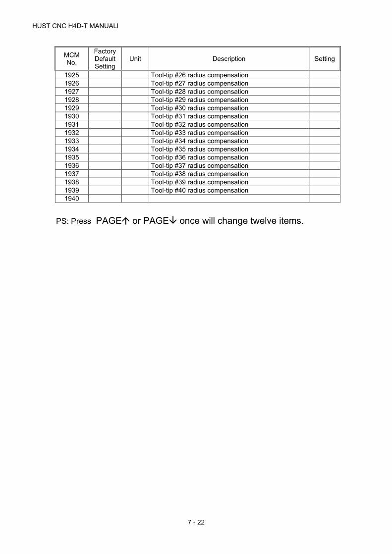
HUST CNC H4D-T MANUALl
7 - 22
MCM No.
Factory Default Setting
Unit Description Setting
1925 Tool-tip #26 radius compensation 1926 Tool-tip #27 radius compensation 1927 Tool-tip #28 radius compensation 1928 Tool-tip #29 radius compensation 1929 Tool-tip #30 radius compensation 1930 Tool-tip #31 radius compensation 1931 Tool-tip #32 radius compensation 1932 Tool-tip #33 radius compensation 1933 Tool-tip #34 radius compensation 1934 Tool-tip #35 radius compensation 1935 Tool-tip #36 radius compensation 1936 Tool-tip #37 radius compensation 1937 Tool-tip #38 radius compensation 1938 Tool-tip #39 radius compensation 1939 Tool-tip #40 radius compensation 1940
PS: Press PAGE or PAGE once will change twelve items.

7 MCM PARAMETERS
7 - 23
7.1 Description of MCM Machine Constants
The decimal format for MCM data in this section is based on 4/3 format.
MCM #1~#36 are for G54~G59 work coordinates data. The setting value is the
distance between the origin of each work coordinate system and the machine
HOME position. All input data have the same format and unit as shown below:
1. G54 (1st) Work Coordinate, X-axis.
2. G54 (1st) Work Coordinate, Y-axis.
3. G54 (1st) Work Coordinate, Z-axis.
4. G54 (1st) Work Coordinate, A-axis.
5. G54 (1st) Work Coordinate, B-axis.
6. G54 (1st) Work Coordinate, C-axis.
7. G54 (1st) Work Coordinate, U-axis.
8. G54 (1st) Work Coordinate, V-axis.
9. G54 (1st) Work Coordinate, W-axis.
Format:□.□□□,Unit: mm (Default=0.000)
MCM# 10~20 System Reserved!
21. G55 (2nd) Work Coordinate, X-axis.
22. G55 (2nd) Work Coordinate, Y-axis.
23. G55 (2nd) Work Coordinate, Z-axis.
24. G55 (2nd) Work Coordinate, A-axis.
25. G55 (2nd) Work Coordinate, B-axis.
26. G55 (2nd) Work Coordinate, C-axis.
27. G55 (2nd) Work Coordinate, U-axis.
28. G55 (2nd) Work Coordinate, V-axis.
29. G55 (2nd) Work Coordinate, W-axis.
Format:□.□□□,Unit: mm (Default=0.000)
MCM# 30~40 System Reserved!
41. G56 (3rd) Work Coordinate, X-axis.
42. G56 (3rd) Work Coordinate, Y-axis.
43. G56 (3rd) Work Coordinate, Z-axis.
44. G56 (3rd) Work Coordinate, A-axis.

HUST CNC H4D-T MANUALl
7 - 24
45. G56 (3rd) Work Coordinate, B-axis.
46. G56 (3rd) Work Coordinate, C-axis.
47. G56 (3rd) Work Coordinate, U-axis.
48. G56 (3rd) Work Coordinate, V-axis.
49. G56 (3rd) Work Coordinate, W-axis.
Format:□.□□□,Unit: mm (Default=0.000)
MCM# 50~60 System Reserved!
MCM# 61~69 G57 (4th) Work Coordinate.
MCM# 70~80 System Reserved!
MCM# 81~89 G58 (5th) Work Coordinate.
MCM# 90~100 System Reserved!
MCM# 101~109 G59 (6th) Work Coordinate.
MCM# 110~120 System Reserved!
MCM Parameters 121~160 are used for setting the coordinates of the
reference point. Its value is the mechanical coordinates of the reference point
relative to the mechanical origin.
121. G28 1st Reference Point Data, X-axis.
122. G28 1st Reference Point Data, Y-axis.
123. G28 1st Reference Point Data, Z-axis.
124. G28 1st Reference Point Data, A-axis.
125. G28 1st Reference Point Data, B-axis.
126. G28 1st Reference Point Data, C-axis.
127. G28 1st Reference Point Data, U-axis.
128. G28 1st Reference Point Data, V-axis.
129. G28 1st Reference Point Data, W-axis.
Format:□.□□□,Unit: mm (Default=0.000)
MCM# 130~140 System Reserved!
141. G30 2st Reference Point Data, X-axis.
142. G30 2st Reference Point Data, Y-axis.
143. G30 2st Reference Point Data, Z-axis.
144. G30 2st Reference Point Data, A-axis.

7 MCM PARAMETERS
7 - 25
145. G30 2st Reference Point Data, B-axis.
146. G30 2st Reference Point Data, C-axis.
147. G30 2st Reference Point Data, U-axis.
148. G30 2st Reference Point Data, V-axis.
149. G30 2st Reference Point Data, W-axis.
Format:□.□□□,Unit: mm (Default=0.000)
MCM# 150~160 System Reserved!
161. Backlash Compensation (G01), X-axis.
162. Backlash Compensation (G01), Y-axis.
163. Backlash Compensation (G01), Z-axis.
164. Backlash Compensation (G01), A-axis.
165. Backlash Compensation (G01), B-axis.
166. Backlash Compensation (G01), C-axis.
167. Backlash Compensation (G01), U-axis.
168. Backlash Compensation (G01), V-axis.
169. Backlash Compensation (G01), W-axis.
Format:□.□□□,Unit: pulse (Default=0) Range:0~9.9999
MCM# 170~180 System Reserved!
181. Backlash Compensation (G00), X-axis.
182. Backlash Compensation (G00), Y-axis.
183. Backlash Compensation (G00), Z-axis.
184. Backlash Compensation (G00), A-axis.
185. Backlash Compensation (G00), B-axis.
186. Backlash Compensation (G00), C-axis.
187. Backlash Compensation (G00), U-axis.
188. Backlash Compensation (G00), V-axis.
189. Backlash Compensation (G00), W-axis.
Format:□.□□□,Unit: pulse (Default=0) Range:0~9.9999
MCM# 170~200 System Reserved!
201. Jog Speed, X-axis.
202. Jog Speed, Y-axis.
203. Jog Speed, Z-axis.
204. Jog Speed, A-axis.
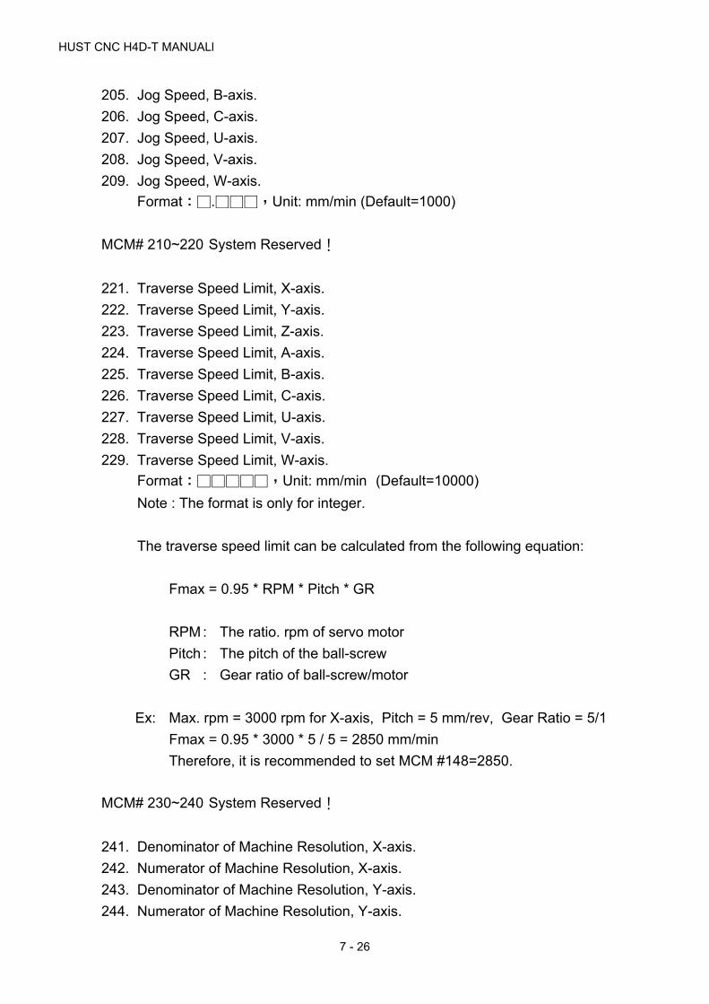
HUST CNC H4D-T MANUALl
7 - 26
205. Jog Speed, B-axis.
206. Jog Speed, C-axis.
207. Jog Speed, U-axis.
208. Jog Speed, V-axis.
209. Jog Speed, W-axis.
Format:□.□□□,Unit: mm/min (Default=1000)
MCM# 210~220 System Reserved!
221. Traverse Speed Limit, X-axis.
222. Traverse Speed Limit, Y-axis.
223. Traverse Speed Limit, Z-axis.
224. Traverse Speed Limit, A-axis.
225. Traverse Speed Limit, B-axis.
226. Traverse Speed Limit, C-axis.
227. Traverse Speed Limit, U-axis.
228. Traverse Speed Limit, V-axis.
229. Traverse Speed Limit, W-axis.
Format:□□□□□,Unit: mm/min (Default=10000)
Note : The format is only for integer.
The traverse speed limit can be calculated from the following equation:
Fmax = 0.95 * RPM * Pitch * GR
RPM : The ratio. rpm of servo motor
Pitch : The pitch of the ball-screw
GR : Gear ratio of ball-screw/motor
Ex: Max. rpm = 3000 rpm for X-axis, Pitch = 5 mm/rev, Gear Ratio = 5/1
Fmax = 0.95 * 3000 * 5 / 5 = 2850 mm/min
Therefore, it is recommended to set MCM #148=2850.
MCM# 230~240 System Reserved!
241. Denominator of Machine Resolution, X-axis.
242. Numerator of Machine Resolution, X-axis.
243. Denominator of Machine Resolution, Y-axis.
244. Numerator of Machine Resolution, Y-axis.

7 MCM PARAMETERS
7 - 27
245. Denominator of Machine Resolution, Z-axis.
246. Numerator of Machine Resolution, Z-axis
247. Denominator of Machine Resolution, A-axis.
248. Numerator of Machine Resolution, A-axis
249. Denominator of Machine Resolution, B-axis.
250. Numerator of Machine Resolution, B-axis
251. Denominator of Machine Resolution, C-axis.
252. Numerator of Machine Resolution, C-axis
253. Denominator of Machine Resolution, U-axis.
254. Numerator of Machine Resolution, U-axis
255. Denominator of Machine Resolution, V-axis.
256. Numerator of Machine Resolution, V-axis
257. Denominator of Machine Resolution, W-axis.
258. Numerator of Machine Resolution, W-axis
Format:□.□□□,(Default=100)
Denominator (D) = pulses/rev for the encoder on motor.
Numerator (N) = pitch length (mm/rev) of the ball-screw.
Gear Ratio (GR) = Tooth No. on ball-screw / Tooth No. on motor.
Pulse Multiplication Factor (MF) = MCM #416~#469.
Ex1: X-axis as linear axis (MCM #781=0), pitch = 5 mm = 5000 m
Encoder = 2500 pulses, MCM #461 = 4, and GR = 5 (motor rotates
5 times while ball-screw rotates once)
Machine resolution = 5000/(2500 × 4)/5 = 5000/50000 = 1/10 = 0.1
m/pulse
Therefore, the setting value for MCM #118 (D) and #119 (N) can be
set as or the same ratio of N/D such as. They are all correct.
(1) D=50000, N=5000 (2) D=10, N=1 (3) D=100, N=10
Ex2: Y-axis as rotating axis (MCM #782=1), Angle = 360.000 deg/circle
Encoder = 2500 pulses, MCM #161 = 4, and GR = 5 (motor rotates
5 times while ball-screw rotates once)
Machine Resolution =(Pitch of Ball - screw)
(Encoder Pulse) * (MF)*
1
GR

HUST CNC H4D-T MANUALl
7 - 28
Machine resolution = 360000/(2500 × 4)/5 = 360000/50000 = 36/5
=72/10
Therefore, the setting value for MCM #120 (D) and #121 (N) can be
one of the three combinations. They are all correct.
(1) D=5, N=36 (2) D=10, N=72 (3) D=50000, N=360000
Ex 3 (Position Linear Axis):
The X-axis is an ordinary linear axis (MCM#781= 0) with the guide screw pitch
= 5.000 mm.
When the motor rotates one turn, 10000 pulses will be generated.
Gear ratio is 5:1 (When the servo motor rotates 5 turns, the guide screw
rotates 1 turn.)
X-axis resolution: denominator setting value (MCM#241)= 10
X-axis resolution: numerator setting value (MCM#242)= 1
Ex 4 (Position type rotational axis):
The Y-axis is a rotational axis (MCM#782 = 1). The angle for rotating 1 turn =
360.000 (degree)
One turn of the motor will generate 10000 pulses.
Gear ratio is 5:1 (When the servo motor rotates 5 turns, the Y-axis rotates 1
turn.)
Y-axis resolution: denominator setting value (MCM#243) = 5
Y-axis resolution: numerator setting value (MCM#244) = 36
1
5
1
10=
Resolution = × 5000
10000
1
5
36
5 =
Resolution = × 360000
10000
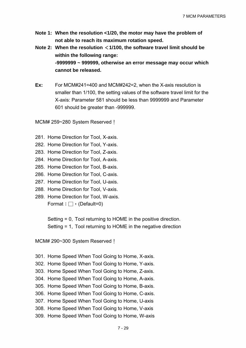
7 MCM PARAMETERS
7 - 29
Note 1: When the resolution <1/20, the motor may have the problem of
not able to reach its maximum rotation speed.
Note 2: When the resolution <1/100, the software travel limit should be
within the following range:
-9999999 ~ 999999, otherwise an error message may occur which
cannot be released.
Ex: For MCM#241=400 and MCM#242=2, when the X-axis resolution is
smaller than 1/100, the setting values of the software travel limit for the
X-axis: Parameter 581 should be less than 9999999 and Parameter
601 should be greater than -999999.
MCM# 259~280 System Reserved!
281. Home Direction for Tool, X-axis.
282. Home Direction for Tool, Y-axis.
283. Home Direction for Tool, Z-axis.
284. Home Direction for Tool, A-axis.
285. Home Direction for Tool, B-axis.
286. Home Direction for Tool, C-axis.
287. Home Direction for Tool, U-axis.
288. Home Direction for Tool, V-axis.
289. Home Direction for Tool, W-axis.
Format:□,(Default=0)
Setting = 0, Tool returning to HOME in the positive direction.
Setting = 1, Tool returning to HOME in the negative direction
MCM# 290~300 System Reserved!
301. Home Speed When Tool Going to Home, X-axis.
302. Home Speed When Tool Going to Home, Y-axis.
303. Home Speed When Tool Going to Home, Z-axis.
304. Home Speed When Tool Going to Home, A-axis.
305. Home Speed When Tool Going to Home, B-axis.
306. Home Speed When Tool Going to Home, C-axis.
307. Home Speed When Tool Going to Home, U-axis
308. Home Speed When Tool Going to Home, V-axis
309. Home Speed When Tool Going to Home, W-axis

HUST CNC H4D-T MANUALl
7 - 30
Format:□□□□,Unit: mm/min (Default=2500)
MCM# 310~320 System Reserved!
321. Home Grid Speed When Tool Going to Home, X-axis.
322. Home Grid Speed When Tool Going to Home, Y-axis.
323. Home Grid Speed When Tool Going to Home, Z-axis.
324. Home Grid Speed When Tool Going to Home, A-axis.
325. Home Grid Speed When Tool Going to Home, B-axis.
326. Home Grid Speed When Tool Going to Home, C-axis.
327. Home Grid Speed When Tool Going to Home, U-axis.
328. Home Grid Speed When Tool Going to Home, V-axis.
329. Home Grid Speed When Tool Going to Home, W-axis.
Format:□□□□,Unit: mm/min (Default=40)
MCM# 330~340 System Reserved!
341. The direction that servo motor search the Grid when X-axis going back to
HOME.
342. The direction that servo motor search the Grid when Y-axis going back to
HOME.
343. The direction that servo motor search the Grid when Z-axis going back to
HOME.
344. The direction that servo motor search the Grid when A-axis going back to
HOME.
345. The direction that servo motor search the Grid when B-axis going back to
HOME.
346. The direction that servo motor search the Grid when C-axis going back to
HOME.
347. The direction that servo motor search the Grid when U-axis going back to
HOME.
348. The direction that servo motor search the Grid when V-axis going back to
HOME.
349. The direction that servo motor search the Grid when W-axis going back
to HOME.
Format:□,(Default=0)
EX:
When MCM#341= 0, the 2nd and 3rd direction is the same with 1st

7 MCM PARAMETERS
7 - 31
MCM#341= 1, the 2nd is the same with 1st .
MCM#341= 128, the 2nd direction is opposite to 1st .
MCM#341= 256, the 2nd and 3rd direction is opposite to 1st .
Set the moving speed when the tool, after having touched the HOME limit
switch, is searching for the encoder grid signal during HOME execution.
HUST H4D/HD/H9D CNC has three (3) different speeds when you
execute HOME function as shown by Fig 7.2.
Speed 1: The motor accelerates to Speed 1 and its maximum speed is
determined by the settings of MCM #301 ~ #309, (X, Y, Z, A, B,
C, U, V, W-axis) and the direction by MCM #281 ~ #289. When
tool touches the home limit switch, it starts deceleration to a
stop.
Speed 2: The motor accelerates again to speed 2 and its maximum
speed is equal to 1/4 of Speed 1 and the direction is by MCM
#341~#349. When tool starts leaving the home limit switch, it
starts deceleration to a stop.
Speed 3: The motor accelerates to speed 3 and its maximum speed is
determined by the settings of MCM #321~#329 and the
direction by MCM #341~#349. Once the encoder grid index is
found, motor decelerates to a stop. This is the HOME position.
Note that the length of the Home limit switch should be longer than the
distance for the deceleration of Speed 1. Otherwise, serious error may
result. The equation to calculate the length of the Home limit switch is
Length of Home Limit Switch (mm) FDCOM * ACC
60000
FDCOM = Speed 1, in mm/min. (MCM #301~ #309)
ACC = Time for acceleration/deceleration, in ms. (MCM #505)
60000 = 60 seconds = 60 * 1000 milliseconds
When the C-bit C063=1 in PLC program, it commands the controller to do
homing operation. Do homing operation for X-axis if R232=1, do Y-axis if
R232=2, do Z –axis if R232=4 , do A–axis if R232=8 and do four axes
simultaneously if R232=15.
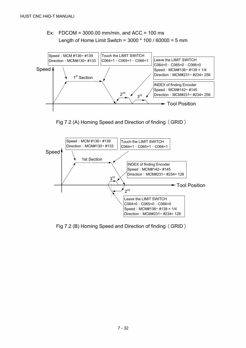
HUST CNC H4D-T MANUALl
7 - 32
Ex: FDCOM = 3000.00 mm/min, and ACC = 100 ms
Length of Home Limit Switch = 3000 * 100 / 60000 = 5 mm
Fig 7.2 (A) Homing Speed and Direction of finding(GRID)
Fig 7.2 (B) Homing Speed and Direction of finding(GRID)
Speed
3rd 2nd
Tool Position
1st Section
Speed:MCM #136~ #139 Direction:MCM#130~ #133
Touch the LIMIT SWITCH C064=1、C065=1、C066=1 Leave the LIMIT SWITCH
C064=0、C065=0、C066=0 Speed:MCM#136~ #139 × 1/4 Direction:MCM#231~ #234= 256
INDEX of finding Encoder Speed:MCM#142~ #145 Direction:MCM#231~ #234= 256
3rd
2nd
Tool Position
1st Section
Touch the LIMIT SWITCH C064=1、C065=1、C066=1
Leave the LIMIT SWITCH C064=0、C065=0、C066=0 Speed:MCM#136~ #139 × 1/4 Direction:MCM#231~ #234= 128
INDEX of finding Encoder Speed:MCM#142~ #145 Direction:MCM#231~ #234= 128
Speed
Speed:MCM #136~ #139 Direction:MCM#130~ #133

7 MCM PARAMETERS
7 - 33
Fig 7-2(C) Homing Speed and Direction of finding(GRID)
Fig 7-2(D) Homing Speed and Direction of finding(GRID)
MCM# 350~360 System Reserved!
361. Setting the X-Home grid setting.
362. Setting the Y-Home grid setting.
363. Setting the Z-Home grid setting.
364. Setting the A-Home grid setting.
365. Setting the B-Home grid setting.
366. Setting the C-Home grid setting.
367. Setting the U-Home grid setting.
368. Setting the V-Home grid setting.
369. Setting the W-Home grid setting.
3rd
2nd
Tool Position
1st Section
Touch the LIMIT SWITCH C064=1、C065=1、C066=1
Leave the LIMIT SWITCH C064=0、C065=0、C066=0 Speed:MCM#136~ #139 × 1/4 Direction:MCM#231~ #234= 1
INDEX of finding Encoder Speed:MCM#142~ #145 Direction:MCM#231~ #234= 1
Speed
Speed:MCM #136~ #139 Direction:MCM#130~ #133
Speed:MCM #136~ #139 Direction:MCM#130~ #133
3rd 2nd Tool Position
Speed Touch the LIMIT SWITCH C064=1、C065=1、C066=1
Leave the LIMIT SWITCH C064=0、C065=0、C066=0 Speed:MCM#136~ #139 × 1/4 Direction:MCM#231~ #234= 0
INDEX of finding Encoder Speed:MCM#142~ #145 Direction:MCM#231~ #234= 0
1st Section
HUST CNC H4D-T MANUALl
7 - 34
Format=□□□□.□□□ (Default=0.000), unit: mm
Leaving from the origin switch signal, deviating from the above set
distance, and then you can start to execute the Homing process (third
section) to locate the motor Gird signal.
MCM# 370~380 System Reserved!
381. Home-Shift Data, X-axis.
382. Home-Shift Data, Y-axis.
383. Home-Shift Data, Z-axis.
384. Home-Shift Data, A-axis.
385. Home-Shift Data, B-axis.
386. Home-Shift Data, C-axis.
387. Home-Shift Data, U-axis.
388. Home-Shift Data, V-axis.
389. Home-Shift Data, W-axis.
Format:□.□□□,Unit: mm/min (Default=0.000)
Set the amount of coordinate shift for HOME location (or machine origin).
With these settings, the machine coordinate will be shifted by the same
amount when you execute "Home". If home shift data are zero for all
axes, the machine coordinate after "Home" operation will be zero also.
Note that the work coordinate will be shifted by the same amount.
MCM# 390~400 System Reserved!
401. The distance that servo motor search the Grid when X-axis going back to
HOME.
402. The distance that servo motor search the Grid when Y-axis going back to
HOME.
403. The distance that servo motor search the Grid when Z-axis going back to
HOME.
404. The distance that servo motor search the Grid when A-axis going back to
HOME.
405. The distance that servo motor search the Grid when B-axis going back to
HOME.
406. The distance that servo motor search the Grid when C-axis going back to
HOME.
7 MCM PARAMETERS
7 - 35
407. The distance that servo motor search the Grid when U-axis going back to
HOME.
408. The distance that servo motor search the Grid when V-axis going back to
HOME.
409. The distance that servo motor search the Grid when W-axis going back
to HOME.
Format=□□□□.□□□ (Default 10.000)
The distance’s maximum when servo motor searching the Grid signal:
EX:
The servo motor of X-axis turns 3/4 round = 5.000 mm, MCM# 401 = 5.200
The servo motor of Y-axis turns 3/4 round = 5.000 mm, MCM# 402 = 5.200
The servo motor of Z-axis turns 3/4 round = 5.000 mm, MCM# 403 = 5.200
The servo motor of A-axis turns 3/4 round = 5.000 mm, MCM# 404 = 5.200
The servo motor of B-axis turns 3/4 round = 5.000 mm, MCM# 405 = 5.200
The servo motor of C-axis turns 3/4 round = 5.000 mm, MCM# 406 = 5.200
※ If it exceeds the range and the motor can not find the Grid still. ERR15 will
be shown up.
MCM# 410~420 System Reserved!
421. X-axis origin switch (+: N.O node; -: N.C node)
422. Y -axis origin switch (+: N.O node; -: N.C node)
423. Z -axis origin switch (+: N.O node; -: N.C node)
424. A-axis origin switch (+: N.O node; -: N.C node)
425. B -axis origin switch (+: N.O node; -: N.C node)
426. C-axis origin switch (+: N.O node; -: N.C node)
427. U-axis origin switch (+: N.O node; -: N.C node
428. V-axis origin switch (+: N.O node; -: N.C node
429. W-axis origin switch (+: N.O node; -: N.C node
Example: MCM 421=5
Set I5 to be the X-axis origin signal with format NO
MCM 425=-6
Set I6 to be the A-axis origin signal with format NC
HUST CNC H4D-T MANUALl
7 - 36
※ Default = 0, Funcitons are inactive, ≠ 0, Functions are active.
※ If a homing process with C64-69 is planned in PLC, it shall be
based on the activity set by PLC.
MCM# 430~440 System Reserved!
441. Direction of Motor Rotation, X-axis.
442. Direction of Motor Rotation, Y-axis.
443. Direction of Motor Rotation, Z-axis.
444. Direction of Motor Rotation, A-axis.
445. Direction of Motor Rotation, B-axis.
446. Direction of Motor Rotation, C-axis.
447. Direction of Motor Rotation, U-axis.
448. Direction of Motor Rotation, V-axis.
449. Direction of Motor Rotation, W-axis.
Format:□,(Default=0)
Setting = 0, Motor rotates in the positive direction. (CW)
Setting = 1, Motor rotates in the negative direction. (CCW)
This MCM can be used to reverse the direction of motor rotation if desired.
So you don’t have to worry about the direction of rotation when installing
motor. These parameters will affect the direction of HOME position
IMPORTANT: Motor Divergence Due to the variations in circuit design of the servo drivers that are available from the market, the proper electrical connections from servo encoder to the driver, then to the CNC controller may vary. If the connections do not match properly, the motor RPM may become divergent (Rotate @ HIGH RPM) and damage to the machine may result. For this reason, HUST strongly suggest separate the servo motor and the machine before you are 100% sure the direction of the motor rotation. If a motor divergence occurs, please inter-change the connections of (A and B phase) and (A- and B- phase) on the driver side. (This statement has nothing to do with MCM #154~ #157 but it’s very important when connecting electrical motor.)
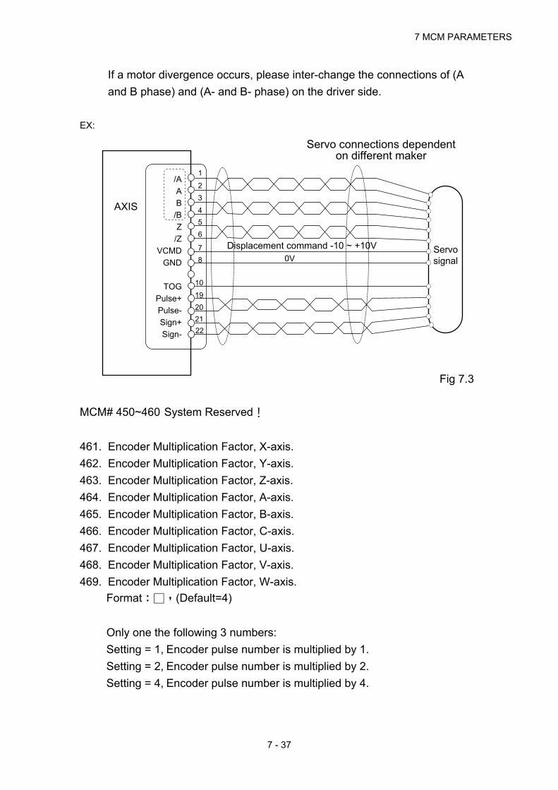
7 MCM PARAMETERS
7 - 37
If a motor divergence occurs, please inter-change the connections of (A
and B phase) and (A- and B- phase) on the driver side.
EX:
Fig 7.3
MCM# 450~460 System Reserved!
461. Encoder Multiplication Factor, X-axis.
462. Encoder Multiplication Factor, Y-axis.
463. Encoder Multiplication Factor, Z-axis.
464. Encoder Multiplication Factor, A-axis.
465. Encoder Multiplication Factor, B-axis.
466. Encoder Multiplication Factor, C-axis.
467. Encoder Multiplication Factor, U-axis.
468. Encoder Multiplication Factor, V-axis.
469. Encoder Multiplication Factor, W-axis.
Format:□,(Default=4)
Only one the following 3 numbers:
Setting = 1, Encoder pulse number is multiplied by 1.
Setting = 2, Encoder pulse number is multiplied by 2.
Setting = 4, Encoder pulse number is multiplied by 4.
Servo connections dependent on different maker
Displacement command -10 ~ +10V 0V
1
3
/A
A
B
/B
Z
/Z
VCMD
GND
TOG
Pulse+
Pulse-
Sign+
Sign-
AXIS
10
19
20
21
22
Servo signal
2
4
5
6
7
8
HUST CNC H4D-T MANUALl
7 - 38
Note:
The setting of multiplication is highly relative with machine’s rigidity. If a motor
divergence occurs too heavily, it means that the rigidity is too big. And then it
can be improved by lowering the multiplication.
Ex: If factor = 2 for MCM #161 and the encoder resolution is 2000
pulses/rev,
then the feed-back signals = 2000 * 2 = 4000 pulses/rev for Y-axis.
MCM# 470~480 System Reserved!
481. X-axis impulse command width adjustment.
482. Y-axis impulse command width adjustment.
483. Z-axis impulse command width adjustment.
484. A-axis impulse command width adjustment.
485. B-axis impulse command width adjustment.
486. C-axis impulse command width adjustment.
487. U-axis impulse command width adjustment.
488. V-axis impulse command width adjustment.
489. W-axis impulse command width adjustment.
Format=□□ (Default=4)
Setting range 1~63。
Used to adjust each axial impulse command width
If the pulse frequency from H4D/H6D/H9D controller is 1Hz, then the
cycle time of a pulse is 0.25us. If it is required to extend the pulse cycle
time, it can be achieved through adjust ment of the impulse width.
For example:
If MCM 486=4, the impulse cycle time in the X-axis direction is
4*0.25=1.5us and the frequency is 625KHz.
MCM# 490~500 System Reserved!
501. Master/Slave Mode Setting
Format:□.□□□,(Default=0)
Setting = 0, CNC mode, Master/Slave mode NOT set.
= 1, X-axis as master axis, Y, Z, A, B, C, U, V, W-axis as slave axes.

7 MCM PARAMETERS
7 - 39
= 2, Y-axis as master axis, X, Z, A, B, C, U, V, W -axis as slave axes.
= 3, Z-axis as master axis, X, Y, A, B, C, U, V, W -axis as slave axes.
= 4, A-axis as master axis, X, Y, Z, B, C, U, V, W -axis as slave axes.
= 5, B-axis as master axis, X, Y, Z, A, C, U, V, W -axis as slave axes.
= 6, C-axis as master axis, X, Y, Z, A, B, U, V, W -axis as slave axes.
= 7, U-axis as master axis, X, Y, Z, A, B, C, V, W -axis as slave axes.
= 8, V-axis as master axis, X, Y, Z, A, B, C, U, W -axis as slave axes.
= 9, W-axis as master axis, X, Y, Z, A, B, C, U, V -axis as slave axes.
= 256, Round Corner Non-stop Operation
502. Type of Motor Acceleration/Deceleration
Format:□,(Default=1)
Setting = 1, Linear type.
Setting = 2, "S" curve.
503. Home command mode setting.
BIT0 = 0 X axis find Home grid available, =1 X axis no need to find Home grid.
BIT1 = 0 Y axis find Home grid available, =1 Y axis no need to find Home grid.
BIT2 = 0 Z axis find Home grid available, =1 Z axis no need to find Home grid.
BIT3 = 0 A axis find Home grid available, =1 A axis no need to find Home grid.
BIT4 = 0 B axis find Home grid available, =1 B axis no need to find Home grid.
BIT5 = 0 C axis find Home grid available, =1 C axis no need to find Home grid.
BIT6 = 0 U axis find Home grid available, =1 U axis no need to find Home grid.
BIT7 = 0 V axis find Home grid available, =1 V axis no need to find Home grid.
BIT8 = 0 W axis find Home grid available, =1 W axis no need to find Home grid.
504. Servo Motor Acceleration/Deceleration Time, G00.
Format:□□□,Unit: millisecond (Default=100)
Setting Range: 2 ~ 3000 millisecond
505. Servo Motor Acceleration/Deceleration Time (T), G01.
Format:□□□,Unit: millisecond (Default=100)
Setting Range: 2 ~ 3000 millisecond.
100 milliseconds is the recommended setting for both G00 and G01.
If MCM #502 setting = 0, type of accel./decel. for G01 = exponential
If MCM #502 setting = 1, type of accel./decel. for G01 = Linear.
If MCM #502 setting = 2, type of acceleration/deceleration for G01 = "S"

HUST CNC H4D-T MANUALl
7 - 40
curve. In this case, the actual acceleration/deceleration time is twice the
setting value.
506. Acceleration/Deceleration Time for G99 Mode.
Format:□□□,Unit: Millisecond (Default=100)
Setting Range: 4 ~ 3000 ms.
507. Set the spindle Acceleration/Deceleration time in master mode.
Format:□□□,Unit: Millisecond (Default=100)
Setting Range: 4 ~ 3000 ms.
508. Spindle Encoder Pulse Per Revolution
Format:□□□□,Unit: Pulse/rev (Default=4096)
509. Set Spindle Motor RPM When Vcmd = 10 Volt.
Format:□□□□,Unit: RPM (Default=3000)
510. Spindle voltage command 0V output balance adjustment (open circuit).
511. Spindle voltage command slope correction (open circuit).
Format:S= □□□□,(Default=0), Set the reference value 2047.
512. Spindle RPM correction (based on feedback from the encoder).
513. Starting Number for Auto Generation of Program Block Number.
Format:S= □,(Default=0)
514. Increment for Auto-generation of Program Block Number.
Format:D= □,(Default=0)
515. If D = 0, the program block number of a single program block will not be
generated automatically.
In the Edit or Teach mode, the block number of a single block can be
automatically generated by simply press the INSERT key. If the RESET
key is pressed, the block number of a single block will be renumbered
according to the setting values in Parameters 514 and 515.
Ex: S = 0 , D = 5
The program block number will be generated in the sequence:
5,10,15,20,25 …

7 MCM PARAMETERS
7 - 41
516. Denominator of Feed-rate Multiplication Factor for MPG Test.
517. Numerator of Feed-rate Multiplication Factor for MPG Test.
Format:□□□□□,(Default=100)
Note: If the MPG rotation speed is not proper, it can be adjusted by
MCM#516, #517. The two items are up to 5 units and it must be integer.
They also can not set as zero.
518. Handwheel direction
Format=□ (Default= 0).
If it is necessary to change the relation between the current handwheel
rotational direction and the axial displacement direction, it can be
achieved by setting the value to 0 or 1.
It can be adjusted separately the corresponding axial direction bit 0 =x
bit 1 =y....
Example: BIT 0=1 The X-axis handwheel command is reverse, but other
axes remain at the default.
519. Set Acceleration / Deceleration Time for MPG
Format=□□□, (Default = 64), Unit: milliseconds
Setting Range: 4~512 ms.
The motor acceleration / deceleration time is equal to MCM #519 when
MPG hand-wheel is used in JOG mode.
520. RS232C Baud Rate.
Format:□□□□,(Default = 38400)
Set RS232C communication speed. Choose from, 9600, 19200, 38400,
57600, 115200 Speed rate 38400 stands for 38400 bits per second.
In addition, use the following settings for your PC:
Parity -- Even

HUST CNC H4D-T MANUALl
7 - 42
Stop Bits -- 2 bits
Data Bits – 7 bits
521. Flag to Save the Data of R000~R199 in PLC when power-off.
Format:□,(Default=0)
Setting = 0, NOT to save.
Setting = 256, Save R000~R199 data.
522. Servo Error Count
Format:□,(Default=0)
When executing locating operation, the controller has sent out the
voltage command, but the motor maybe fall behind some distance. This
parameter is used to set that the controller could execute next operation
or not according to the setting range of pulse
Set MCM#522 = 0 for generating 4096 pulses.
Set MCM#522 0 for user defined value.
523. Radius / diameter programming mode
Format=□ (Default = 0)
0: Radius programming
1: Diameter programming
524. METRIC/INCH Mode Selection (default = 0)
Format:□□□,(Default = 0)
Setting = 0, Measurement in METRIC unit.
Setting = 1, Measurement in INCH unit.
525. Error in Circular Cutting
Format:□□□□,(Default = 1)
Range:1 ~ 32
In circular cutting, the ideal cutting path is a circular arc, but the actual
motor path is along the arc cord (a straight line). Therefore, there is a
cutting error as shown in the figure below.

7 MCM PARAMETERS
7 - 43
Fig 7.4
This parameter enables the user to adjust acceptable error. The smaller
is the setting (=1, the best), the better the circular cutting result. However,
the setting should not be too small to the point that it’s not able to drive
the motor.
526. 6-axis parameter settings in pulse type
Format =□□□□, Default: 0
Setting =0: pulse + direction
Setting =1: +/- pulse
Setting =2: in the format of Phase A or B
527. Setting the G01 speed value at booting
Format=□□□□□□□ (Default=1000)
After booting, in executing the program or MDI command, if you have not
used the F command yet, nor the current single block has designated the
F value, then use the MCM 527 value as the F value of the current single
block.
528. Setting the tool compensation direction
Format=□ (Default=0)
0:HUST
1:FANUC
Tool-wear compensation direction - HUST: same direction; FANUC:
reverse direction.
529. It is used for adjusting the G01’s acceleration/deceleration time when the
acceleration/deceleration type is set to an “S” curve.
Cutting Error
The less the setting set; the
better the circular arc cut.
HUST CNC H4D-T MANUALl
7 - 44
Format=□□□ (Default=100) in unit of millisecond (msec).
When MCM 502=2, the function can then be sustained.
Setting range 10~512 ms.
531. Line editing entry format and numeral decimal’s automatic-generating
setting.
Format=□ (default setting 0)
=0 The standard mode.
=1 When setting the parameter values in the system master list, the
system will automatically add a decimal point to even numbers.
Ex:MCM 401 setting
Enter ”1 " =1.000
Enter ”nter ng=1.999
=2 Line Editing.
Ex:Enter G00 X10.
Standard mode steps:
Step 1 Step 2 Step 3 Step 4
GOO ENTER X10. ENTER
Line editing:
Step 1 Step 2
GOO X10. ENTER
=4 At editing, decimal point will be automatically generated for the
variable value.
At program editing and also entering even numbers, the system
will automatically add decimal point to even numbers.
532. In the milling mode, set the gap for drill to withdraw.
Format=□. □□□ (Default= 2.000) unit:mm
533. Setting the test following count
Format=□□□□□□□ (Default= 0)
With use of parameter Item No.534
534. Testing the axial setting of the servo following error function
Format=□□□ (Default = 0)
Set the testing corresponding to the axis with Bit

7 MCM PARAMETERS
7 - 45
Description:
When MCM534=1 and Bit0 = 1, test the X-axus.
When MCM534=2 and Bit1 = 1, test the Y-axis.
When MCM534=4 and Bit2 = 1, test the Z-axis.
When MCM534=8 and Bit3 = 1, test the A-axis.
When MCM534=16 and Bit4 = 1, test the B-axis.
When MCM534=32 and Bit5 = 1, test the C-axis.
When MCM534=64 and Bit6 = 1, test the U-axis.
When MCM534=128 and Bit7 = 1, test the V-axis.
When MCM534=256 and Bit8 = 1, test the W-axis.
When MCM534=511, i.e. Bit0 ~ Bit8= 1, then test X/Y/Z/A/B/C/U/V/W-
axes at the same time.
Caution: For HUST H4D/H6D/H9D controller, if the servo motor used
is a voltage command type, it is necessary to set testing the
following error function ( not applicable for the impulse command
type).
The controller will compare the actual feedback difference of the servo
motor with the setting of the parameter Item No 533. If the controller
detects that the axis has been set beyond the range, the system will
display an error message.
Example: When the parameter Item No 533= 4096, the parameter Item
No 534=1, and
The actual motor following error
>
4096 (Parameter Item No 533), it will generate ERROR 02 X
535. Controller ID number
Control connection of multiple units with PC. Currently, the function is
reserved.

HUST CNC H4D-T MANUALl
7 - 46
536. Setting the minimum slope of the Auto Teach function
Format=□□□□□.□□ (Default= 0)
Setting range: +360.00 ~ -360.00
537. Setting the first point distance of the Auto Teach function.
Format=□□□□.□□□ (Default= 0)
538. G41 and G42 Handling type
Format=□ (Default 0)
When the setting value =0, an error is displayed, the interference problem
is not handelled, and the motion is stopped.
=1 Automactilly handle the interference problem.
=2 The error message is not displayed and the interference problem is
not handeled.
539. System Reserved
540. Adjustment of the feedback direction for the axes
Format=□□□ (Default 0)
Set the corresponding axes by the bit pattern.
Description:
If MCM540=1, Bit0 = 1, the feedback direction is reverse for the X-axis.
If MCM540=2, Bit1 = 1, the feedback direction is reverse for the Y-axis.
If MCM540=4, Bit2 = 1, the feedback direction is reverse for the Z-axis.
If MCM540=8, Bit3 = 1, the feedback direction is reverse for the A-axis.
If MCM540=16, Bit4 = 1, the feedback direction is reverse for the B-axis.
If MCM540=32, Bit5 = 1, the feedback direction is reverse for the C-axis.
If MCM540=64, Bit6 = 1, the feedback direction is reverse for the U-axis.
If MCM540=128, Bit7 = 1, the feedback direction is reverse for the V-
axis.
If MCM540=256, Bit8 = 1, the feedback direction is reverse for the W-
axis.
541. Arc type
Format=□ (Default 0)
Setting =0 arc cord height control.

7 MCM PARAMETERS
7 - 47
=1 arc cord length control.
=2 system internal automatic control (500 sections/sec).
MCM# 542~560 System Reserved!
561. “S” curve accel./decel. profile setting for the X-axis.
562. “S” curve accel./decel. profile setting for the Y-axis.
563. “S” curve accel./decel. profile setting for the Z-axis.
564. “S” curve accel./decel. profile setting for the A-axis.
565. “S” curve accel./decel. profile setting for the B-axis.
566. “S” curve accel./decel. profile setting for the C-axis.
567. “S” curve accel./decel. profile setting for the U-axis.
568. “S” curve accel./decel. profile setting for the V-axis.
569. “S” curve accel./decel. profile setting for the W-axis.
When R209 Bit30=1, the “S” curve accel./decel. profile settings can be
configured independently.
MCM# 570~580 System Reserved!
581. Software OT Limit in (+) Direction, X-axis. (Group 1)
582. Software OT Limit in (+) Direction, Y-axis. (Group 1)
583. Software OT Limit in (+) Direction, Z-axis. (Group 1)
584. Software OT Limit in (+) Direction, A-axis. (Group 1)
585. Software OT Limit in (+) Direction, B-axis. (Group 1)
586. Software OT Limit in (+) Direction, C-axis. (Group 1)
587. Software OT Limit in (+) Direction, U-axis. (Group 1)
588. Software OT Limit in (+) Direction, V-axis. (Group 1)
589. Software OT Limit in (+) Direction, W-axis. (Group 1)
Format:□□□□□□□,Unit: mm/min (Default=9999.999)
Set the software over-travel (OT) limit in the positive (+) direction, the
setting value is equal to the distance from positive OT location to the
machine origin (HOME).
MCM# 590~600 System Reserved!
601. Software OT Limit in (-) Direction, X-axis. (Group 1)
602. Software OT Limit in (-) Direction, Y-axis. (Group 1)
HUST CNC H4D-T MANUALl
7 - 48
603. Software OT Limit in (-) Direction, Z-axis. (Group 1)
604. Software OT Limit in (-) Direction, A-axis. (Group 1)
605. Software OT Limit in (-) Direction, B-axis. (Group 1)
606. Software OT Limit in (-) Direction, C-axis. (Group 1)
607. Software OT Limit in (-) Direction, U-axis. (Group 1)
608. Software OT Limit in (-) Direction, V-axis. (Group 1)
609. Software OT Limit in (-) Direction, W-axis. (Group 1)
Format:□□□□.□□□,Unit: mm/min (Default=-9999.999)
Set the software over-travel (OT) limit in the negative (-) direction, the
setting value is equal to the distance from negative OT location to the
machine origin (HOME). Figure below shows the relationship among the
software OT limit, the emergency stop, and the actual hardware limit.
MCM# 610~620 System Reserved!
621. Software OT Limit in (+) Direction, X-axis. (Group 2)
622. Software OT Limit in (+) Direction, Y-axis. (Group 2)
623. Software OT Limit in (+) Direction, Z-axis. (Group 2)
624. Software OT Limit in (+) Direction, A-axis. (Group 2)
625. Software OT Limit in (+) Direction, B-axis. (Group 2)
626. Software OT Limit in (+) Direction, C-axis. (Group 2)
627. Software OT Limit in (+) Direction, U-axis. (Group 2)
628. Software OT Limit in (+) Direction, V-axis. (Group 2)
629. Software OT Limit in (+) Direction, W-axis. (Group 2)
Format:□□□□□□□,Unit: mm/min (Default=9999.999)
※In PLC when C10=1, it detects unit 2 software’s range limit.
※,Set the software over-travel (OT) limit in the positive (+) direction, the
setting value is equal to the distance from positive OT location to the
machine origin (HOME).
MCM# 630~640 System Reserved!
641. Software OT Limit in (-) Direction, X-axis. (Group 2)
642. Software OT Limit in (-) Direction, Y-axis. (Group 2)
643. Software OT Limit in (-) Direction, Z-axis. (Group 2)
644. Software OT Limit in (-) Direction, A-axis. (Group 2)
645. Software OT Limit in (-) Direction, B-axis. (Group 2)

7 MCM PARAMETERS
7 - 49
646. Software OT Limit in (-) Direction, C-axis. (Group 2)
647. Software OT Limit in (-) Direction, U-axis. (Group 2)
648. Software OT Limit in (-) Direction, V-axis. (Group 2)
649. Software OT Limit in (-) Direction, W-axis. (Group 2)
Format:□□□□.□□□,Unit: mm/min (Default=-9999.999)
※nIn PLC when C10=1, it detects unit 2 software’s range limit.
※,Set the software over-travel (OT) limit in the negative (-) direction, the
setting value is equal to the distance from negative OT location to the
machine origin (HOME).
Fig 7.5
MCM# 650~660 System Reserved!
661. Flag to Clear X-axis Program Coordinate on M02, M30 or M99 Command.
662. Flag to Clear Y-axis Program Coordinate on M02, M30 or M99 Command.
663. Flag to Clear Z-axis Program Coordinate on M02, M30, or M99 Command.
664. Flag to Clear A-axis Program Coordinate on M02, M30, or M99 Command.
665. Flag to Clear B-axis Program Coordinate on M02, M30, or M99 Command.
666. Flag to Clear C-axis Program Coordinate on M02, M30, or M99 Command.
667. Flag to Clear U-axis Program Coordinate on M02, M30, or M99 Command.
668. Flag to Clear V-axis Program Coordinate on M02, M30, or M99 Command.
669. Flag to Clear W-axis Program Coordinate on M02, M30, or M99
Command.
Format:□,(Default=0)
Used as flag to clear the coordinate when program execution encounters
M02, M30 or M99 function. The following settings are valid for both X and
Y-axis.
Machine Origin
Software OT Limit
(MCM#581~ #649)
5~10 mm each Actual Hardware Limit
Emergency
HUST CNC H4D-T MANUALl
7 - 50
Setting = 0, Flag is OFF, NOT to clear.
Setting = 1, Flag is ON, YES to clear when encountering M02 and M30.
Setting = 2, Flag is ON, YES to clear when encountering M99.
Setting = 3, Flag is ON, YES to clear when encountering M02, M30 and
M99.
MCM# 670~680 System Reserved!
681. Set Incremental/Absolute Mode, X-axis coordinate.
682. Set Incremental/Absolute Mode, Y-axis coordinate.
683. Set Incremental/Absolute Mode, Z-axis coordinate.
684. Set Incremental/Absolute Mode, A-axis coordinate.
685. Set Incremental/Absolute Mode, B-axis coordinate.
686. Set Incremental/Absolute Mode, C-axis coordinate.
687. Set Incremental/Absolute Mode, U-axis coordinate.
688. Set Incremental/Absolute Mode, V-axis coordinate.
689. Set Incremental/Absolute Mode, W-axis coordinate.
Format:□,(Default=1) for absolute positioning
Ex: Set MCM 681 = 0, X value represents the incremental position and
U value is ineffective.
= 1, X value represents the incremental position and
U value is the incremental position.
*Note 1: After the parameters are set, execute the command G01
X***,Y***,Z*** F***, the program will perform the axial motions
according to the configured incremental or absolute positions.
H9D: When R209 = 4, the incremental address codes of
X,Y,Z will be U,V,W. However, the A,B,C axes have no
incremental address code, they cannot be used in the
same way as the X,Y,Z axes which allow the
conversion between the incremental positioning and the
absolute positioning. It is necessary to use the
G90/G91 modes to use them.
H9D: X,Y,Z,A,B,C,U,V,W have no incremental address codes,
so they cannot allow the conversion between the
incremental positioning and the absolute positioning. It
is necessary to use the G90/G91 mode to use them.

7 MCM PARAMETERS
7 - 51
*Note 2: For H9D using the incremental address codes U,V,W, it is
necessary to set the parameters 1 of the X,Y,Z axes for the
absolution positioning so that the U,V,W commands can be
performed in the program.
*Note 3: If the G90/G91 mode is used for the 9-axis absolute or
incremental positioning change, no matter the parameters are
configured for absolution positioning or for incremental
positioning, the single block X,Y,Z,A,B,C,U,V,W commands
will use the G90/G91 mode for absolute positioning or
absolute increments after the G90/G91 mode is used.
*Note 4: When the controller in H9D is configured to use U,V,W as the
incremental address codes, it will not be influenced by the
G90/G91 mode.
Format of mode appointment:
G90 Absolute coordinate
G91 Incremental coordinate
1. G90 :
When writing G90 in the program, all the axes of X,Y,Z,A,B,C,U,V,W are the
absolute coordinate. All following nodes` axes direction will also feed absolutely.
(See EX1)
The incremental codes U,V,W also can be used in G90 mode. Then X, Y, Z
axes will feed incrementally. But A-axis still feed absolutely. Until it meeting G91
or recycling the program, then the G90 will be over.
EX1: G90 Set Absolute Coordinate
N1 G90
N2 G1 X20.000 Y15.000 .... P0 to P1
N3 X35.000 Y25.000 .... P1 to P2
N4 X60.000 Y30.000 .... P2 to P3
2. G91 :
When writing G90 in the program, all the axes of X,Y,Z,A,B,C,U,V,W are the
incremental coordinate. All following nodes` axes direction will also feed
incrementally. (See EX2)
In G91 mode, X,Y,Z represent the incremental value. The codes of U, V, W are
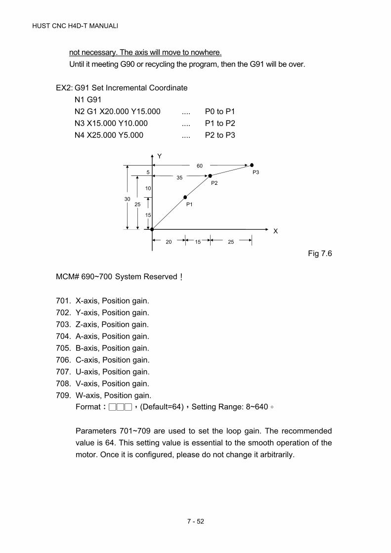
HUST CNC H4D-T MANUALl
7 - 52
not necessary. The axis will move to nowhere.
Until it meeting G90 or recycling the program, then the G91 will be over.
EX2: G91 Set Incremental Coordinate
N1 G91
N2 G1 X20.000 Y15.000 .... P0 to P1
N3 X15.000 Y10.000 .... P1 to P2
N4 X25.000 Y5.000 .... P2 to P3
Fig 7.6
MCM# 690~700 System Reserved!
701. X-axis, Position gain.
702. Y-axis, Position gain.
703. Z-axis, Position gain.
704. A-axis, Position gain.
705. B-axis, Position gain.
706. C-axis, Position gain.
707. U-axis, Position gain.
708. V-axis, Position gain.
709. W-axis, Position gain.
Format:□□□,(Default=64),Setting Range: 8~640。
Parameters 701~709 are used to set the loop gain. The recommended
value is 64. This setting value is essential to the smooth operation of the
motor. Once it is configured, please do not change it arbitrarily.
15
10
5
25 30
20 15 25
Y
X
P1
P2
P360
35

7 MCM PARAMETERS
7 - 53
Fig 7-7 Driver output voltage vs. the servo error
The position gain and HUST H4D/H6D/H9D output voltage command
can be calculated as follows:
Position Gain = Setting value
64
NC controller output voltage command
= GAIN * Servo feedback error * ( )
The controller in HUST is a closed-loop system. The servo error is the
difference between the controller position command and the actual
feedback value of the servo motor. The controller will adjust the output
voltage of the controller properly according to this difference value. The
setting value of the position gain is related to the stability and the follow-
up of the system servo, so please modify it with care. If:
Servo mismatch > 4096, the ERROR 02 will occur.
In this case, please correct the values of MCM Parameters 701~709 and
then press the “Reset” key. If the problem still exists, please check if the
wire connection of the servo motor is correct.
Adjustment procedure for smooth motor operation: (recommended)
10V
2048
1024 2046 4096 Servo error (ERROR COUNT)
N=128/64 N=64/64 N=32/64 DC10V VCMD
Driver output voltage

HUST CNC H4D-T MANUALl
7 - 54
(1) Adjust the servo driver. (Please refer to the operation manual of the
driver)
(2) Adjust the MCM Parameters 461~469 for the multipliers (1,2,4) of
the signals from the the speed sensors. In normal condition, if the
motor is locked, the Servo Error will be oscillating between 0 and 1;
if it is oscillating between 4 and 5, the problem can be solved
usually by adjusting the MCM Parameters 461 ~ 469 for the
multipliers, i.e., 4 --> 2, or 2 --> 1.
(3) Adjust the values of MCM Parameters 701~709 for the position
loop gain.
MCM# 710~720 System Reserved!
721. Break-over Point (in Error Count) for Position Gain, X-axis.
722. Break-over Point (in Error Count) for Position Gain, Y-axis.
723. Break-over Point (in Error Count) for Position Gain, Z-axis.
724. Break-over Point (in Error Count) for Position Gain, A-axis.
725. Break-over Point (in Error Count) for Position Gain, B-axis.
726. Break-over Point (in Error Count) for Position Gain, C-axis.
727. Break-over Point (in Error Count) for Position Gain, U-axis.
728. Break-over Point (in Error Count) for Position Gain, V-axis.
729. Break-over Point (in Error Count) for Position Gain, W-axis.
Format:□□□,(Default=10)
The proper setting of this parameter will assure smooth start-up of servo
motor. When servo error is smaller than the setting value of MCM
#721~#729, the position gain is 64. Otherwise, position gain will be
calculated based on the setting value of MCM #701~ #709 and the
setting values depend on the frictional load on the motor. If the frictional
load is high, setting value is small and vice versa.

7 MCM PARAMETERS
7 - 55
Fig 7.7
MCM# 730~740 System Reserved!
741. X-axis Denominator, MPG Hand-wheel Resolution Adjustment. (pulse)
742. X-axis Numerator, MPG Hand-wheel Resolution Adjustment. (m)
743. Y-axis Denominator, MPG Hand-wheel Resolution Adjustment. (pulse)
744. Y-axis Numerator, MPG Hand-wheel Resolution Adjustment. (m)
745. Z-axis Denominator, MPG Hand-wheel Resolution Adjustment. (pulse)
746. Z-axis Numerator, MPG Hand-wheel Resolution Adjustment. (m)
747. A-axis Denominator, MPG Hand-wheel Resolution Adjustment. (pulse)
748. A-axis Numerator, MPG Hand-wheel Resolution Adjustment. (m)
749. B-axis Denominator, MPG Hand-wheel Resolution Adjustment. (pulse)
750. B-axis Numerator, MPG Hand-wheel Resolution Adjustment. (m)
751. C-axis Denominator, MPG Hand-wheel Resolution Adjustment. (pulse)
752. C-axis Numerator, MPG Hand-wheel Resolution Adjustment. (m)
753. U-axis Denominator, MPG Hand-wheel Resolution Adjustment. (pulse)
754. U-axis Numerator, MPG Hand-wheel Resolution Adjustment. (m)
755. V-axis Denominator, MPG Hand-wheel Resolution Adjustment. (pulse)
756. V-axis Numerator, MPG Hand-wheel Resolution Adjustment. (m)
757. W-axis Denominator, MPG Hand-wheel Resolution Adjustment.
(pulse)
10 20 30 40 50 60 70 80
0
0.05
0.10
0.15
0.20
Vcmd
Controller
Command
ERROR = 10
ERROR COUNT
GAIN = 128/64 GAIN = 64/64 GAIN = 32/64

HUST CNC H4D-T MANUALl
7 - 56
758. W-axis Numerator, MPG Hand-wheel Resolution Adjustment. (m)
Format:□□□□,(Default = 100)
Unit: Denominator = pulses, Numerator = m
Ex1: For X-axis, MCM #741 = 100 pulses, MCM #742 = 100 m.
The resolution for X-axis = 100/100 = 1 m/pulse.
If MPG hand-wheel moves 1 notch (=100 pulses), the feed length in
X-axis = 100 x (100/100) = 100 m = 0.1 mm.
Ex2: For Y-axis, MCM #743 = 200 pulses, MCM #744 = 500 m.
The resolution for Y-axis = 500/200 = 2.5 m/pulse.
If MPG hand-wheel moves 1 notch (=100 pulses), the feed length in
Y-axis = 100 x (500/200) = 250 m = 0.25 mm.
MCM# 759~780 System Reserved!
781. Set if X-axis is rotational axis.
782. Set if Y-axis is rotational axis.
783. Set if Z-axis is rotational axis.
784. Set if A-axis is rotational axis.
785. Set if B-axis is rotational axis.
786. Set if C-axis is rotational axis.
787. Set if U-axis is rotational axis.
788. Set if V-axis is rotational axis.
789. Set if W-axis is rotational axis.
Format=□ (Default 0)
Setting= 0 Linear Axis
Setting= 1 Rotational Axis
MCM# 787~800 System Reserved!
801. The distance of S bit sent before the X-axis reaches in position. (S176)
802. The distance of S bit sent before the Y-axis reaches in position. (S177)
803. The distance of S bit sent before the Z-axis reaches in position. (S178)
804. The distance of S bit sent before the A-axis reaches in position. (S179)
805. The distance of S bit sent before the B-axis reaches in position. (S180)
806. The distance of S bit sent before the C-axis reaches in position. (S181)
807. The distance of S bit sent before the U-axis reaches in position. (S182)
7 MCM PARAMETERS
7 - 57
808. The distance of S bit sent before the V-axis reaches in position. (S183)
809. The distance of S bit sent before the W-axis reaches in position. (S184)
Format=□□□□.□□□ (Default= 0.000)
Unit: mm
For example: MCM 801 =10.00mm
Giving the command: When G01 U30.000 F1000, when the X-axis
move 20.000mm and 10.000mm away from the final value, the sysem
will send S176=ON。
MCM# 807~820 System Reserved!
821. The accelerate/decelerate time of X-axis.
822. The accelerate/decelerate time of Y-axis.
823. The accelerate/decelerate time of Z-axis.
824. The accelerate/decelerate time of A-axis.
825. The accelerate/decelerate time of B-axis.
826. The accelerate/decelerate time of C-axis.
827. The accelerate/decelerate time of U-axis.
828. The accelerate/decelerate time of V-axis.
829. The accelerate/decelerate time of W-axis.
Format=□□□□ (Default 0), Unit (msec)
Acceleration/Deceleration Time (2~3000)
When R209 Bit30=1, the acceleration/deceleration speed can be
programmed independently.
MCM# 830~840 System Reserved!
The pitch error compensation of the guide screw in HUST H4D/H6D/H9D is
relative to the mechanical origin as the base point.
841. Pitch Error Compensation Mode Setting, X-axis.
842. Pitch Error Compensation Mode Setting, Y-axis.
843. Pitch Error Compensation Mode Setting, Z-axis.
844. Pitch Error Compensation Mode Setting, A-axis.
845. Pitch Error Compensation Mode Setting, B-axis.
846. Pitch Error Compensation Mode Setting, C-axis.
847. Pitch Error Compensation Mode Setting, U-axis.
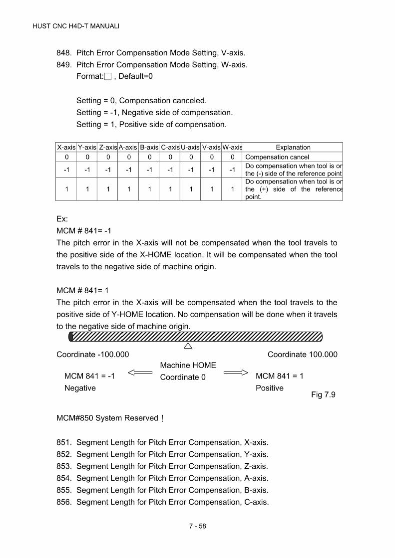
HUST CNC H4D-T MANUALl
7 - 58
848. Pitch Error Compensation Mode Setting, V-axis.
849. Pitch Error Compensation Mode Setting, W-axis.
Format:□ , Default=0
Setting = 0, Compensation canceled.
Setting = -1, Negative side of compensation.
Setting = 1, Positive side of compensation.
X-axis Y-axis Z-axis A-axis B-axis C-axis U-axis V-axis W-axis Explanation
0 0 0 0 0 0 0 0 0 Compensation cancel
-1 -1 -1 -1 -1 -1 -1 -1 -1 Do compensation when tool is onthe (-) side of the reference point
1 1 1 1 1 1 1 1 1 Do compensation when tool is onthe (+) side of the referencepoint.
Ex:
MCM # 841= -1
The pitch error in the X-axis will not be compensated when the tool travels to
the positive side of the X-HOME location. It will be compensated when the tool
travels to the negative side of machine origin.
MCM # 841= 1
The pitch error in the X-axis will be compensated when the tool travels to the
positive side of Y-HOME location. No compensation will be done when it travels
to the negative side of machine origin.
Fig 7.9
MCM#850 System Reserved!
851. Segment Length for Pitch Error Compensation, X-axis.
852. Segment Length for Pitch Error Compensation, Y-axis.
853. Segment Length for Pitch Error Compensation, Z-axis.
854. Segment Length for Pitch Error Compensation, A-axis.
855. Segment Length for Pitch Error Compensation, B-axis.
856. Segment Length for Pitch Error Compensation, C-axis.
Machine HOME
Coordinate 0
Coordinate -100.000 Coordinate 100.000
MCM 841 = 1
Positive
MCM 841 = -1
Negative

7 MCM PARAMETERS
7 - 59
Format=□.□□□, Default=0, Unit=mm
Axis Corresponding MCM# for
Segment Length Segment Length
Max. Number of Segment
X MCM# 861 ~ 940 20 ~ 480 mm 80
Y MCM# 941 ~ 1020 20 ~ 480 mm 80
Z MCM# 1021 ~ 1100 20 ~ 480 mm 80
A MCM# 1101 ~ 1180 20 ~ 480 mm 80
B MCM# 1181 ~ 1260 20 ~ 480 mm 80
C MCM# 1261 ~ 1340 20 ~ 480 mm 80
1. Segment length is the total length of ball-screw divided by the
number of segment.
Fig7.10
Ex:
If you want to divide the ball-screw on X-axis, which is 1 meter in
length, into 10 segments, the segment length is
1000.00/10=100.00mm. This 100.00 mm will be stored in MCM#
851.(Each compensation of them is set by MCM#861~#940)
2. If the average segment length is less than 20 mm, use 20 mm.
3. When doing compensation, HUST H4D/H6D/H9D controller will
further divide each segment into 8 sections. The amount of
compensation for each section is equal to the whole number, in μm,
of 1/8 of the amount in MCM #861~#940. The remainder will be
added to the next section.
Ex:
Segment length =100.00mm and the amount of compensation is
0.026mm as set in MCM#861. Then, the compensation for each section
is 0.026/8=0.00325mm. The compensation for this segment will be done
in a manner as tabulated below:
Section Tool PositionAvg. comp. For each
section Actual comp. At
each section Accumulated compensation
1 12.5 0.00325 0.003 0.003
2 25 0.00325 0.003 0.006
1000 mm
100mm
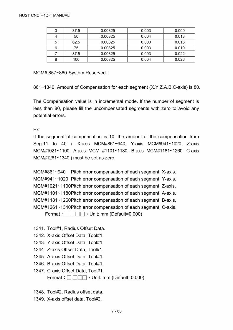
HUST CNC H4D-T MANUALl
7 - 60
3 37.5 0.00325 0.003 0.009
4 50 0.00325 0.004 0.013
5 62.5 0.00325 0.003 0.016
6 75 0.00325 0.003 0.019
7 87.5 0.00325 0.003 0.022
8 100 0.00325 0.004 0.026
MCM# 857~860 System Reserved!
861~1340. Amount of Compensation for each segment (X.Y.Z.A.B.C-axis) is 80.
The Compensation value is in incremental mode. If the number of segment is
less than 80, please fill the uncompensated segments with zero to avoid any
potential errors.
Ex:
If the segment of compensation is 10, the amount of the compensation from
Seg.11 to 40 ( X-axis MCM#861~940, Y-axis MCM#941~1020, Z-axis
MCM#1021~1100, A-axis MCM #1101~1180, B-axis MCM#1181~1260, C-axis
MCM#1261~1340 ) must be set as zero.
MCM#861~940 Pitch error compensation of each segment, X-axis.
MCM#941~1020 Pitch error compensation of each segment, Y-axis.
MCM#1021~1100 Pitch error compensation of each segment, Z-axis.
MCM#1101~1180 Pitch error compensation of each segment, A-axis.
MCM#1181~1260 Pitch error compensation of each segment, B-axis.
MCM#1261~1340 Pitch error compensation of each segment, C-axis.
Format:□.□□□,Unit: mm (Default=0.000)
1341. Tool#1, Radius Offset Data.
1342. X-axis Offset Data, Tool#1.
1343. Y-axis Offset Data, Tool#1.
1344. Z-axis Offset Data, Tool#1.
1345. A-axis Offset Data, Tool#1.
1346. B-axis Offset Data, Tool#1.
1347. C-axis Offset Data, Tool#1.
Format:□.□□□,Unit: mm (Default=0.000)
1348. Tool#2, Radius offset data.
1349. X-axis offset data, Tool#2.

7 MCM PARAMETERS
7 - 61
1350. Y-axis offset data, Tool#2.
1351. Z-axis offset data, Tool#2.
1352. A-axis offset data, Tool#2.
1353. B-axis offset data, Tool#2.
1354. C-axis offset data, Tool#2.
Format:□.□□□,Unit: mm (Default=0.000)
MCM#1355~1620:Tool#3~40, Radius offset data and X/Y/Z/A/B/C-axis
offset data。
1621. Tool #1 radius wear compensation.
1622. X-axis, Tool #1 wear compensation.
1623. Y-axis, Tool #1 wear compensation.
1624. Z-axis, Tool #1 wear compensation.
1625. A-axis, Tool #1 wear compensation.
1626. B-axis, Tool #1 wear compensation.
1627. C-axis, Tool #1 wear compensation.
Format:□.□□□,Unit: mm (Default=0.000)
1628. Tool #2 radius wear compensation.
1629. X-axis, Tool #2 wear compensation.
1630. Y-axis, Tool #2 wear compensation.
1631. Z-axis, Tool #2 wear compensation.
1632. A-axis, Tool #2 wear compensation.
1633. B-axis, Tool #2 wear compensation.
1634. C-axis, Tool #2 wear compensation.
Format:□.□□□,Unit: mm (Default=0.000)
MCM#1635~1900:Tool#3~40, Radius wear compensation and X/Y/Z/A/B/C-
axis wear compensation。
1901~1940:Tool-tip radius compensation(Tool-tip#1~40)

HUST CNC H4D-T MANUALl
7 - 62

8 APPENDIX
8 - 1
8 APPENDIX
Input Arrangement
Input Description Note
I00 EM-STOP Normally Close
I01 X-axis Home Limit Normally Close
I02 Z-axis Home Limit Normally Close
I03 Foot-Switch Talk Switch (PTT)
I04 Option Skip Auto/ Semi-Auto Switch
I05 Spindle Speed Arrival (Reserved)
I06
I07
I08 CYCST (Key) Reserved for the External Panel
I09 Feed Hold (Key) Reserved for the External Panel
I10 Reset (Key) Reserved for the External Panel
I11 Tool Changer (Key) Reserved for the External Panel
I12 No.1 Tool Positioning Signal
I13 No.2 Tool Positioning Signal
I14 No.3 Tool Positioning Signal
I15 No.4 Tool Positioning Signal
I16 No.5 Tool Positioning Signal
I17 No.6 Tool Positioning Signal
I18 No.7 Tool Positioning Signal
I19 No.8 Tool Positioning Signal
I20 Turret Clamp
I21 Bar Feeder Ready
I22
I23
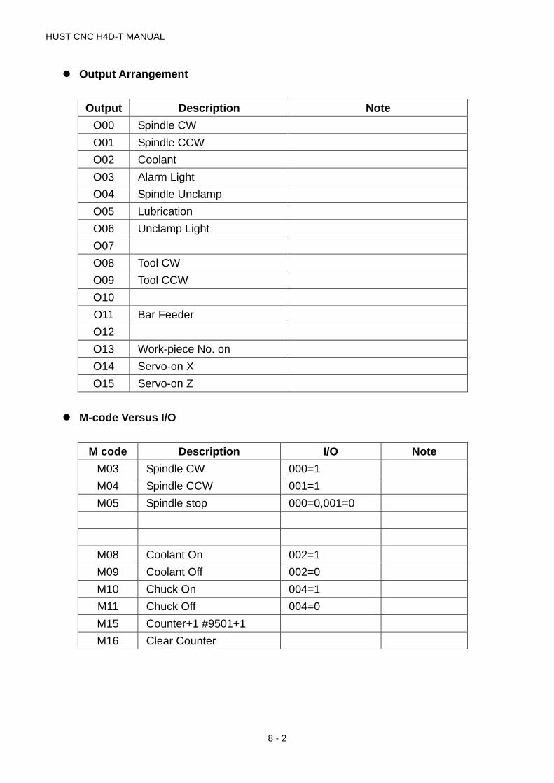
HUST CNC H4D-T MANUAL
8 - 2
Output Arrangement
Output Description Note
O00 Spindle CW
O01 Spindle CCW
O02 Coolant
O03 Alarm Light
O04 Spindle Unclamp
O05 Lubrication
O06 Unclamp Light
O07
O08 Tool CW
O09 Tool CCW
O10
O11 Bar Feeder
O12
O13 Work-piece No. on
O14 Servo-on X
O15 Servo-on Z
M-code Versus I/O
M code Description I/O Note
M03 Spindle CW 000=1
M04 Spindle CCW 001=1
M05 Spindle stop 000=0,001=0
M08 Coolant On 002=1
M09 Coolant Off 002=0
M10 Chuck On 004=1
M11 Chuck Off 004=0
M15 Counter+1 #9501+1
M16 Clear Counter
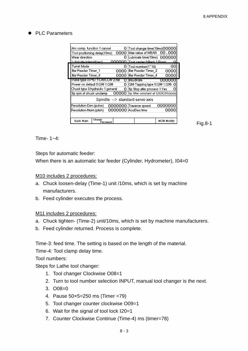
8 APPENDIX
8 - 3
PLC Parameters
Fig.8-1
Time- 1~4:
Steps for automatic feeder:
When there is an automatic bar feeder (Cylinder, Hydrometer), I04=0
M10 includes 2 procedures:
a. Chuck loosen-delay (Time-1) unit /10ms, which is set by machine
manufacturers.
b. Feed cylinder executes the process.
M11 includes 2 procedures:
a. Chuck tighten- (Time-2) unit/10ms, which is set by machine manufacturers.
b. Feed cylinder returned. Process is complete.
Time-3: feed time. The setting is based on the length of the material.
Time-4: Tool clamp delay time.
Tool numbers:
Steps for Lathe tool changer:
1. Tool changer Clockwise O08=1
2. Turn to tool number selection INPUT, manual tool changer is the next.
3. O08=0
4. Pause 50×5=250 ms (Timer =79)
5. Tool changer counter clockwise O09=1
6. Wait for the signal of tool lock I20=1
7. Counter Clockwise Continue (Time-4) ms (timer=78)

HUST CNC H4D-T MANUAL
8 - 4
8. O09=0, Tool changer stops.
Tool numbers ≦1 & >8 Tool changer remains
>1 or <8 Tool changes
Two – six tool numbers can be assigned.
Example: Tool numbers =5
Manual tool changer 1,2,3,4, 1, 2,3… cycle.
TCODE→ tool changes.
T202 → changes to the next tool and select the second set of tool
compensation.
T603→ Tool number remains. Because 6 is bigger than 5, it will select the
third set of tool compensation instead.