lateral forces review concrete
TRANSCRIPT

SE EXAM REVIEW COURSE — August 2017
NCSEA Structural Engineering Exam Review Course
Lateral Forces Review
ConcreteRavi Kanitkar, S.E.

SE EXAM REVIEW COURSE — August 2017
Exam Topics• Shear Walls
– Ordinary, Intermediate, and Special• Moment‐Resisting Frames
– Ordinary, Intermediate, and Special• Ductile Detailing and Anchorage• Diaphragms• Tilt‐up Walls
SE EXAM REVIEW COURSE — August 2017
Review Contents• Overview of Codes• Load Combinations, Prerequisite Information• Reinforcement Development and Splices• Shear Walls• Moment‐Resisting Frames• Ductile Detailing and Anchorage• Tilt‐up Walls• Diaphragms• Final Remarks

SE EXAM REVIEW COURSE — August 2017
Reference Codes for Concrete• IBC 2012: Section 1613 and Chapter 19• ASCE 7‐2010: Excluding Chapter 14 and Appendix 11A (IBC 1613.1)
• ACI 318‐11 (with appropriate amendments per IBC Section 1905)

SE EXAM REVIEW COURSE — August 2017
Applicable Load Combinations• IBC 2012, Section 1605.2
1. 1.2D + 1.0W + f1L + 0.5(Lr or S or R) + 1.6H2. 1.2D + 1.0E + f1L + f2S + 1.6H3. 0.9D + 1.0W + 1.6H4. 0.9D + 1.0E + 1.6H
• ASCE 7‐10, 12.4.2:– E = Eh + 0.2SDSD Use in LC 2– E = Eh – 0.2SDSD Use in LC 4– Eh = QE (QE => V or Fp)
f1 = 0.5 or 1.0 for live loadsf2 = 0.2 or 0.7 for snow loadsSee IBC 1605.2
SE EXAM REVIEW COURSE — August 2017
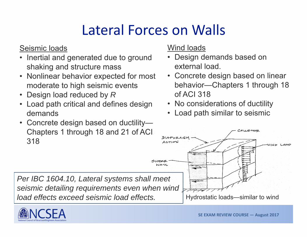
Lateral Forces on WallsWind loads• Design demands based on
external load.• Concrete design based on linear
behavior—Chapters 1 through 18 of ACI 318
• No considerations of ductility• Load path similar to seismic
Seismic loads• Inertial and generated due to ground
shaking and structure mass• Nonlinear behavior expected for most
moderate to high seismic events• Design load reduced by R• Load path critical and defines design
demands• Concrete design based on ductility—
Chapters 1 through 18 and 21 of ACI 318
Hydrostatic loads—similar to wind
Per IBC 1604.10, Lateral systems shall meet seismic detailing requirements even when wind load effects exceed seismic load effects.
SE EXAM REVIEW COURSE — August 2017
Prerequisite Information• Calculation wind design forces• Seismic design category (SDC)
– SDC determined seismic risk level and sets design and detailing requirements
• Seismic design forces–Base shear (Equivalent Lateral Force Procedure, ASCE 7, 12.8 or Simplified Procedure ASCE 7, 12.14)
–Vertical distribution of base shear –Redundancy factor, (ASCE 7, 12.3.4.2)

SE EXAM REVIEW COURSE — August 2017
Reinforcement Development and Splices
SE EXAM REVIEW COURSE — August 2017
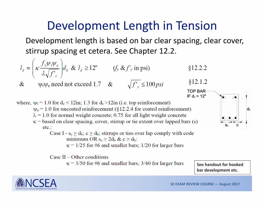
Development Length in TensionDevelopment length is based on bar clear spacing, clear cover, stirrup spacing et cetera. See Chapter 12.2.
See handout for hooked bar development etc.
SE EXAM REVIEW COURSE — August 2017
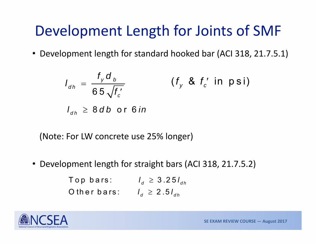
Development Length for Joints of SMF• Development length for standard hooked bar (ACI 318, 21.7.5.1)
(Note: For LW concrete use 25% longer)
• Development length for straight bars (ACI 318, 21.7.5.2)
6 5y b
d hc
f dl
f
( & in p s i)y cf f
8 o r 6d hl d b in
T o p b a rs : 3 .2 5O th e r b a rs : 2 .5
d d h
d d h
l ll l

SE EXAM REVIEW COURSE — August 2017
Lap Splices in Tension• Tension lap splices (ACI 318, 12.15):
Class A lap length = 1.0ldClass B lap length = 1.3ldld = development length (≥ 12in)
• Compression lap splices (ACI 318, 12.16):
But not less than 12in
Note: Column lap splices (ACI 12.17) => Use Class B splice in exam
Note: No splices in regions of plastic hinging
Use Class B lap splices for seismic detailing

SE EXAM REVIEW COURSE — August 2017
Typical Hooks and Bends

SE EXAM REVIEW COURSE — August 2017
Shear Walls

SE EXAM REVIEW COURSE — August 2017
Selection of Wall TypeWALL TYPE DESIGN REQUIREMENTS SDC
Ordinary RC shear walls ACI 318, Chapters 1–18 A, B, CSpecial RC shear walls ACI 318, Chapters 1–8 &
Sections 21.1.3 to 21.1.7, 21.9All
Ordinary precast shear walls
ACI 318, Chapters 1–18 A, B
Intermediate precast shear walls
ACI 318, Chapters 1–18 &Section 21.4
A, B, C
Special precast shear walls
All requirements for Special RC Walls & Section 21.10
All
Refer to ASCE 7, Table 12.2-1 for walls types, R and o, height limitations, and so onAlso see IBC Section 1905 for all Modifications to ACI 318

SE EXAM REVIEW COURSE — August 2017
Reinforced Concrete Shear Walls
MuVu
Flexural reinforcement design
Boundary element requirement
Shear design of concrete and reinforcement
Wall Type SDC Reinf Limits Shear Design
Axial and Flexure Design Other
Ordinary shear wall A, B, C 14.3
11.9.8, 11.9.9 11.9 14.2, 14.310.2, 10.3 —
Specialshear wall ALL 21.9.2 21.9.4 21.9.5
10.2, 10.3
Boundary elements 21.9.6
SE EXAM REVIEW COURSE — August 2017
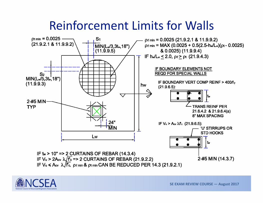
Reinforcement Limits for Walls

SE EXAM REVIEW COURSE — August 2017
Shear Design of WallTwo‐story 12‐in. thick special shear wall = 1.0, SDS = 1.0g, I = 1.0, u = 6 in.f’c = 4000psi, fy = 60ksi
Gravity loads (includes wall weight): DR = 20k, D2nd = 20k; LR = 10k, L2nd = 30k
Seismic loads shownFor first floor wall:
Load combinations:1. (1.2 + 0.2SDS)D + 1.0QE + 0.5L => 2. (0.9 – 0.2SDS)D + 1.0QE =>
Pu Vu Mu76k 110k 2,112k‐ft28k 110k 2,112k‐ft
66k
44k

SE EXAM REVIEW COURSE — August 2017
Shear Design of Wall

SE EXAM REVIEW COURSE — August 2017
Shear Design of WallShear strength (§11.9.5, 11.9.9, and 21.9.4)
Ordinary shear walls (§11.9.4, 11.9.5, 11.9.9)
Special shear walls (§21.9.4)
2
0.82 0.8 (§11.9.5 & 11-29)
where, 0.8 represents effective depth and is horizontal reinforcement.
v y wn c w w
w v
A f LV f t L
s
L d A
(21-7)
Where, Concrete shear area, . 0.6 (if certain that flexure governs, 0.75). §9.3.2.3 & 9.3.4
n cv c c t y cv c c v y
cv w w
V A f f A f A f
A L t
Horizontal shear reinforcement ratio
Factor that varies linearly between / of 1.5 and 2. §21.9.4.1t
c w wh L

SE EXAM REVIEW COURSE — August 2017
Shear Design of Wall

SE EXAM REVIEW COURSE — August 2017
Shear Design of Wall

SE EXAM REVIEW COURSE — August 2017
Flexural Design of Wall• Axial load contributes towards flexural capacity• Controlling load combo (typ): (0.9 – 0.2SDS)D + 1.0QE
• Also check: (1.2 + 0.2SDS)D + 1.0QE + 0.5L

SE EXAM REVIEW COURSE — August 2017
Flexural Design of Wall• Assume all vertical wall (Asw) steel yields (the two final bars at
the compression edge could be neglected)• Compute depth of compression block
• Generally walls are tension controlled elements, (i.e., t ≥ 0.005 at cu = 0.003 and per ACI 9.3.21 & 10.3.4) = 0.9 can be assumed
0 .8 5s w y u
c w
A f Pa
f t
SE EXAM REVIEW COURSE — August 2017
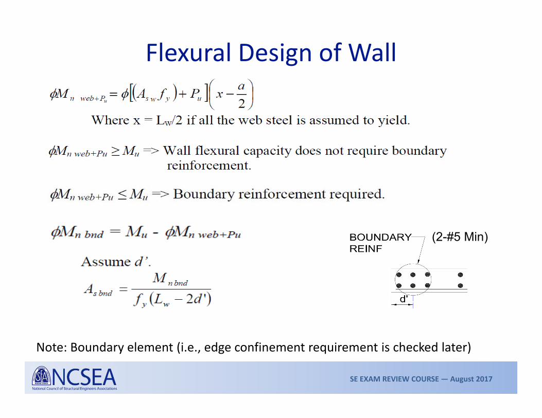
Flexural Design of Wall
Note: Boundary element (i.e., edge confinement requirement is checked later)
(2-#5 Min)
SE EXAM REVIEW COURSE — August 2017
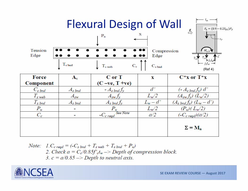
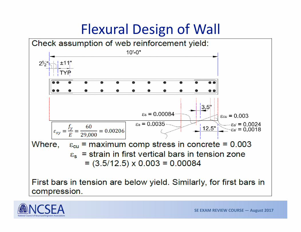
Flexural Design of Wall
(Ref 4)

SE EXAM REVIEW COURSE — August 2017
Flexural Design of Wall

SE EXAM REVIEW COURSE — August 2017
Flexural Design of Wall
SE EXAM REVIEW COURSE — August 2017
Flexural Design of Wall

SE EXAM REVIEW COURSE — August 2017
Flexural Design of Wall

SE EXAM REVIEW COURSE — August 2017
Displacement-based design (Section 21.9.6.2)• Maximum expected displacement, u
• Critical Section with axial loads & flexural yielding
• Typically applies to cantilevered walls
Flexural Design of WallBoundary Element for Special Walls Confinement of compressed edges of walls—two approaches in ACI 318
Force-based design (Section 21.9.6.3)• Apply all axial and lateral loads• Compute maximum compressive stress (axial + flexure)• Applicable to all walls
Possible zone for critical compressive strain

SE EXAM REVIEW COURSE — August 2017
Displacement-Based Design (21.9.6.2)
Boundary elements shall be provided where c ≥ lw / 600(u/hw) Eqn 21-8, &u/hw ≥ 0.007
For u/hw = 0.007, the limit become c ≥ 0.24 lw.Higher the u, lower the threshold for a boundary element.
Neutral axis depth shall be calculated using the designLoad combination (especially factored axial load) thatproduces the design displacement, u;Most likely:
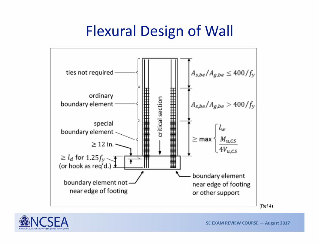
Flexural Design of Wall
lw
Critical Section
Not less than larger of lw or Mu/4Vu
Horz extent of boundary element

SE EXAM REVIEW COURSE — August 2017
Flexural Design of Wall

SE EXAM REVIEW COURSE — August 2017
Flexural Design of Wall

SE EXAM REVIEW COURSE — August 2017
Flexural Design of Wall
SE EXAM REVIEW COURSE — August 2017
Flexural Design of Wall
(Ref 4)

SE EXAM REVIEW COURSE — August 2017
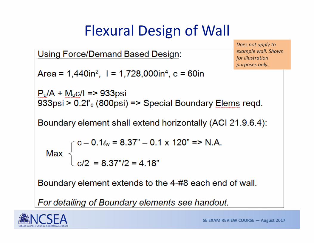
Force/Demand-Based Design (21.9.6.3):
More conservative approach.
Boundary elements shall be provided where the compressive stress due to axial and flexural demands exceeds 0.2f’c.
Discontinue boundary element where compressive stressis less than 0.15f’c.
Stress calculated for factored loads from linearelastic analysis and gross section properties of wall.
Flexural Design of Wall
c > 0.2f’cc < 0.15f’c
SE EXAM REVIEW COURSE — August 2017
Flexural Design of WallDoes not apply to example wall. Shown for illustration purposes only.

SE EXAM REVIEW COURSE — August 2017
Flexural Design of Wall
(Ref 4)

SE EXAM REVIEW COURSE — August 2017
Design of WallOther detailing considerations:
Shear Friction for shear transfer. Use
all vertical web steel. Add dowels if
required & develop for fy
§21.9.2.3 refers to Chapter 12 for bar development & splices
§21.9.2.3(c) Where reinforcement will yield provide laps and development based on 1.25fy
Note: If footing is deep enough, use straight bar development
SE EXAM REVIEW COURSE — August 2017
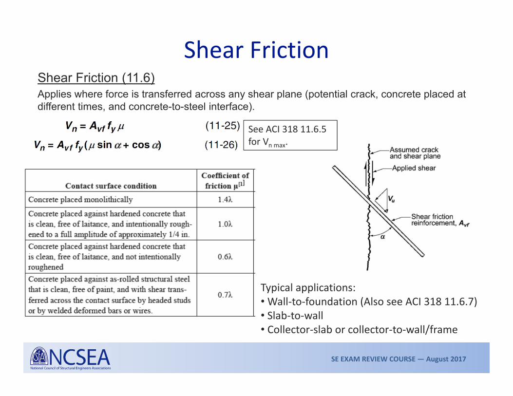
Shear FrictionShear Friction (11.6)Applies where force is transferred across any shear plane (potential crack, concrete placed at different times, and concrete-to-steel interface).
Typical applications:• Wall‐to‐foundation (Also see ACI 318 11.6.7)• Slab‐to‐wall • Collector‐slab or collector‐to‐wall/frame
See ACI 318 11.6.5 for Vn max.

SE EXAM REVIEW COURSE — August 2017
Moment‐Resisting Frames

SE EXAM REVIEW COURSE — August 2017
Selection of Frame Type
Refer to ASCE 7, Table 12.2‐1 for frame types, R and o, height limitations, and so on.
FRAME TYPE DESIGN REQUIREMENTS SDCOrdinary MF ACI 318, Chapters 1–18 &
Section 21.2A, B
Intermediate MF ACI 318, Chapters 1–18 &Section 21.3
A, B, C
Special MF ACI 318, Chapters 1–18 &Section 21‐5 to 21‐8
ALL

SE EXAM REVIEW COURSE — August 2017
Moment FramesMoment frames resist lateral forces by virtue of rigid joints
Beams and columns at the jointare subjected to moments andshears
Goal: Limit damage to frame by appropriate detailing of members and joints

SE EXAM REVIEW COURSE — August 2017
Moment FramesDemands on frames:
Combine with applicable load combinations for design
GRAVITY LOADS LATERAL LOADS

SE EXAM REVIEW COURSE — August 2017
Ordinary Moment Frames• Design for factored loads using provisions of Chapters 1 through 18
• No special detailing requirements, except for SDC B• §21.2.2: Provide at least two main continuous flexural bars top and bottom. Continue through columns or develop these bars at face of support.
• §21.2.3: Columns of OMFs with clear height‐to‐maximum‐plan‐dimension ratio ≤ 5 shall be designed for shear per 21.3.3.2.
Part of the IMF provisions

SE EXAM REVIEW COURSE — August 2017
Intermediate Moment Frames• Design for factored loads using provisions of Chapters 1 through 18 and Section 21.3
• Shear design of beams and columns (21.3.3.1)• Vn shall not be less than smaller of
• shear at nominal moment capacity and shear due to factored gravity loads, or
• shear from load combinations using two times the code prescribed seismic loads.
• Beams (21.3.4)• Lower limits on beam flexural strength
SE EXAM REVIEW COURSE — August 2017
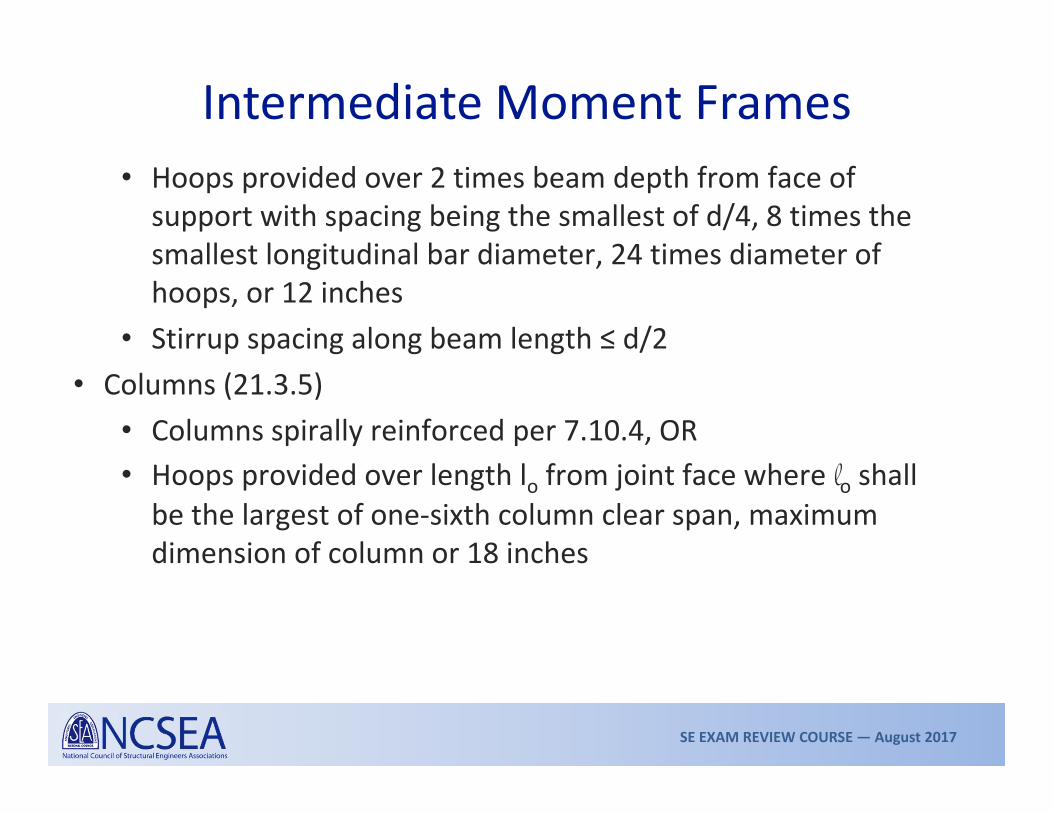
Intermediate Moment Frames• Hoops provided over 2 times beam depth from face of support with spacing being the smallest of d/4, 8 times the smallest longitudinal bar diameter, 24 times diameter of hoops, or 12 inches
• Stirrup spacing along beam length ≤ d/2• Columns (21.3.5)
• Columns spirally reinforced per 7.10.4, OR• Hoops provided over length lo from joint face where lo shall be the largest of one‐sixth column clear span, maximum dimension of column or 18 inches
SE EXAM REVIEW COURSE — August 2017
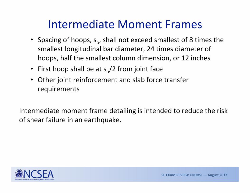
Intermediate Moment Frames• Spacing of hoops, so, shall not exceed smallest of 8 times the smallest longitudinal bar diameter, 24 times diameter of hoops, half the smallest column dimension, or 12 inches
• First hoop shall be at so/2 from joint face• Other joint reinforcement and slab force transfer requirements
Intermediate moment frame detailing is intended to reduce the risk of shear failure in an earthquake.
SE EXAM REVIEW COURSE — August 2017
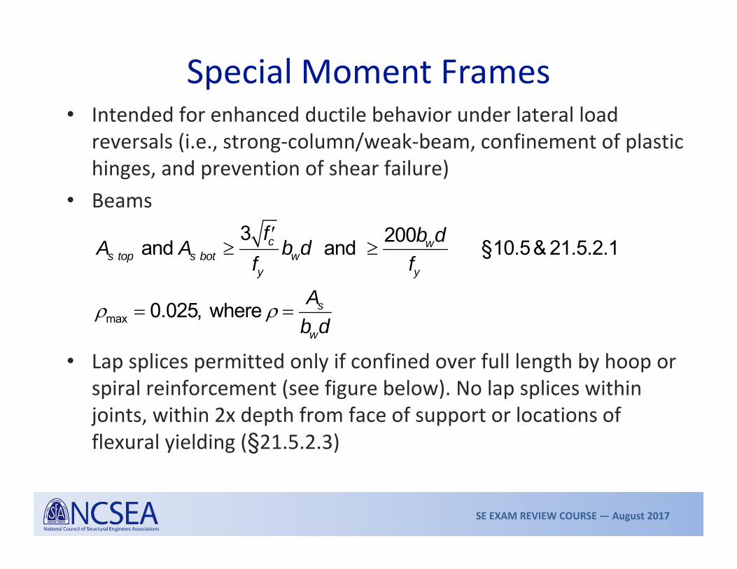
Special Moment Frames• Intended for enhanced ductile behavior under lateral load
reversals (i.e., strong‐column/weak‐beam, confinement of plastic hinges, and prevention of shear failure)
• Beams
• Lap splices permitted only if confined over full length by hoop or spiral reinforcement (see figure below). No lap splices within joints, within 2x depth from face of support or locations of flexural yielding (§21.5.2.3)
max
3 200 and and §10.5& 21.5.2.1
0.025, where
c ws top s bot w
y y
s
w
f b dA A b df f
Ab d

SE EXAM REVIEW COURSE — August 2017
Special Moment FramesBeam Detailing

SE EXAM REVIEW COURSE — August 2017
Special Moment FramesBeams
Mpr = Probable moment strength of section, §21.6.5

SE EXAM REVIEW COURSE — August 2017
Special Moment Frames• Columns• Flexural strength of columns shall satisfy (21.6.2.2) (Eqn 21‐1)
• Longitudinal reinforcement (21.6.3)
65
Where, Sum of nominal flexural strengths of the columns Sum of nominal flexural strengths of the girders
nc nb
nc
nb
M M
MM
0.01 0.06 (Applies to splice as well)Lap splices only within center half of column
g
SE EXAM REVIEW COURSE — August 2017
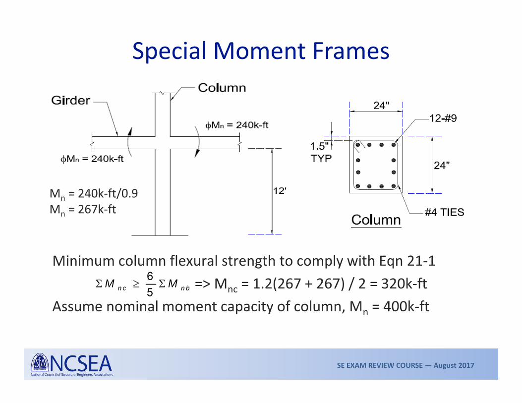
Special Moment Frames
Minimum column flexural strength to comply with Eqn 21‐1 => Mnc = 1.2(267 + 267) / 2 = 320k‐ft
Assume nominal moment capacity of column, Mn = 400k‐ft
Mn = 240k‐ft/0.9 Mn = 267k‐ft
65n c n bM M
SE EXAM REVIEW COURSE — August 2017
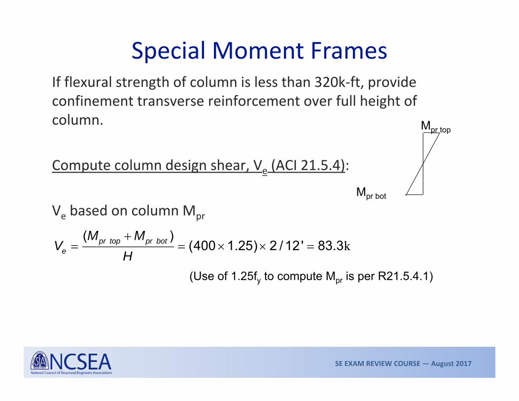
If flexural strength of column is less than 320k‐ft, provide confinement transverse reinforcement over full height of column.
Compute column design shear, Ve (ACI 21.5.4):
Ve based on column Mpr
Special Moment Frames
Mpr top
Mpr bot
k ( )(400 1.25) 2 / 12' 83.3pr top pr bot
e
M MV
H
(Use of 1.25fy to compute Mpr is per R21.5.4.1)
SE EXAM REVIEW COURSE — August 2017
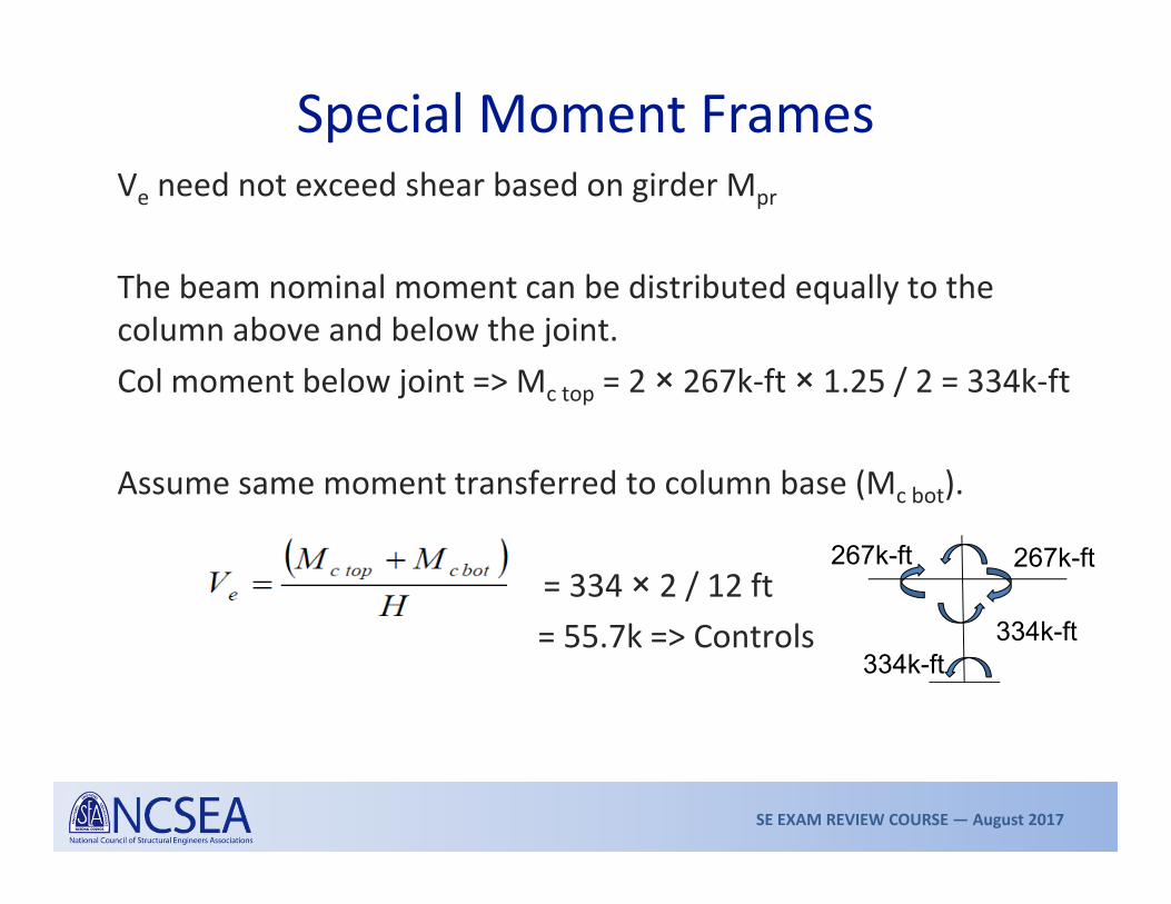
Special Moment FramesVe need not exceed shear based on girder Mpr
The beam nominal moment can be distributed equally to the column above and below the joint.Col moment below joint => Mc top = 2 × 267k‐ft × 1.25 / 2 = 334k‐ft
Assume same moment transferred to column base (Mc bot).
= 334 × 2 / 12 ft = 55.7k => Controls
267k-ft267k-ft
334k-ft334k-ft

SE EXAM REVIEW COURSE — August 2017
Shear capacity of concrete is to be neglected (i.e., Vc = 0) when:
If Vc can be used, it can be computed as
where, = 0.75 (ACI 9.3.4)
Shear reinforcement can be designed per ACI 11.4.7.2.Spacing of ties shall be minimum of 6db or 6 inches (ACI 21.6.4.5). For confinement of plastic hinges other transverse reinforcement requirements apply.
Special Moment Frames

SE EXAM REVIEW COURSE — August 2017
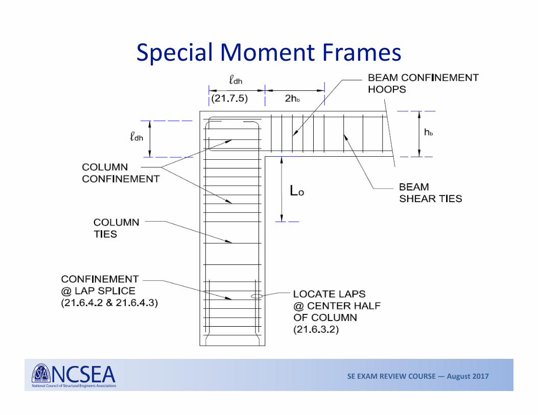
Special Moment FramesColumn hinge confinement and main rebar support• Transverse reinforcement (21.6.4.4)

SE EXAM REVIEW COURSE — August 2017
§21.6.4.1 The ties/spirals computed above are required within Lo as shown in the Figure:
hLo is the greater of H/6
18”
§21.6.4.3 Spacing of transverse reinforcement within Lo shall be the minimum of:
• h/4• 6db
•
so ≤ 6 in. and need not be less than 4 in.where, hx = horizontal spacing of crossties or legs of overlapping hoops (14 in. max).
Special Moment Frames
Two zones are defined for column lateral reinforcement:
• Lo for confinement reinforcement • Lr for ties based on shear demand
1 443
xo
hs
SE EXAM REVIEW COURSE — August 2017
Special Moment Frames

SE EXAM REVIEW COURSE — August 2017
Column P‐M Interaction
Design Points

SE EXAM REVIEW COURSE — August 2017
Tilt‐Up Walls
SE EXAM REVIEW COURSE — August 2017
Tilt‐Up Walls• Tilt‐up and precast walls are designed similar to cast‐in‐place
concrete walls for in‐plane seismic forces• For intermediate and special walls, yielding at the connections
between walls or between walls and foundations shall be restricted to steel elements (plates, etc.) or reinforcement (ACI 21.4.2)
• Elements of the connection not designed to yield shall develop at least 1½ times the yield strength of the connection (ACI 21.4.3)

SE EXAM REVIEW COURSE — August 2017
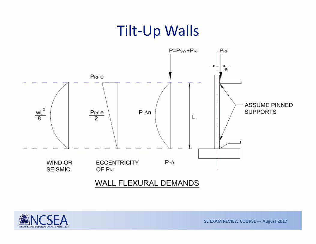
Tilt‐Up Walls• Tilt‐up walls tend to be slender and need to be designed for out‐
of‐plane forces• Wall thickness limits
– Bearing walls: tw ≥ max (supported length/25, 4 inches)– Non‐bearing walls: tw ≥ max (supported length/30, 4 inches)
• A typical slender wall has to resist combined axial and out‐of‐plane flexural demands
• ACI Section 14.8 (Alternative Design of Slender Walls) provisions can be used
SE EXAM REVIEW COURSE — August 2017
Tilt‐Up Walls

SE EXAM REVIEW COURSE — August 2017
Tilt‐Up WallsWall seismic load

SE EXAM REVIEW COURSE — August 2017
Tilt‐Up WallsWall seismic load
Compute Fp at z = 0 and z = hr and use average or use z = hr/2
SE EXAM REVIEW COURSE — August 2017
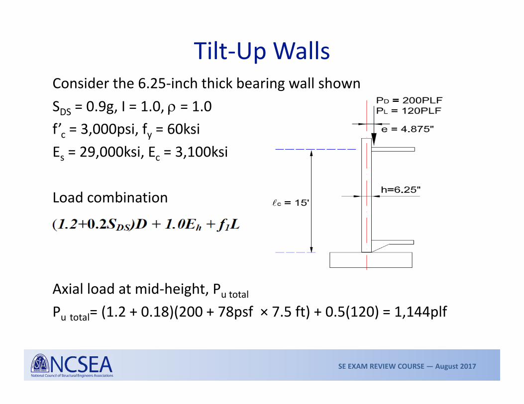
Tilt‐Up WallsConsider the 6.25‐inch thick bearing wall shownSDS = 0.9g, I = 1.0, = 1.0f’c = 3,000psi, fy = 60ksiEs = 29,000ksi, Ec = 3,100ksi
Load combination
Axial load at mid‐height, Pu totalPu total= (1.2 + 0.18)(200 + 78psf × 7.5 ft) + 0.5(120) = 1,144plf

SE EXAM REVIEW COURSE — August 2017
Tilt‐Up WallsSeismic out‐of‐plane forceFp = 0.4(0.9)(1.0)(78psf) = 28psf (>0.1Wp)
Moment at wall mid‐height (per foot width)
Factored roof load = (1.2 + 0.18)(200) + 0.5(120) = 336plfMua = FpL2/8 + Pu Rfe/2Mua = 28 × 152/8 + 336×4.875 in./12in / 2 = 858.8lb‐ft = 10.3k‐in
Per ACI 14.8.3,
SE EXAM REVIEW COURSE — August 2017
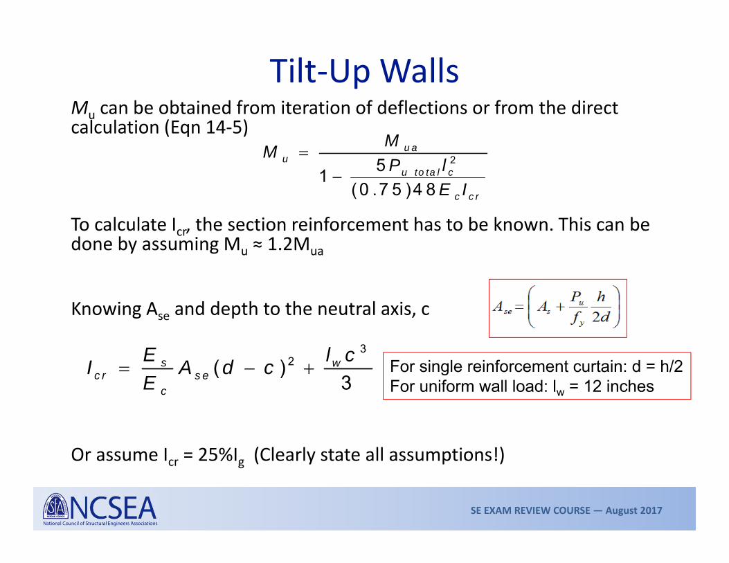
Tilt‐Up WallsMu can be obtained from iteration of deflections or from the direct calculation (Eqn 14‐5)
To calculate Icr, the section reinforcement has to be known. This can be done by assuming Mu ≈ 1.2Mua
Knowing Ase and depth to the neutral axis, c
Or assume Icr = 25%Ig (Clearly state all assumptions!)
For single reinforcement curtain: d = h/2For uniform wall load: lw = 12 inches
2 51
(0 .7 5 )4 8
u au
u to ta l c
c c r
MMP l
E I
32( )
3s w
c r s ec
E l cI A d cE

SE EXAM REVIEW COURSE — August 2017
Tilt‐Up WallsIf the wall has #4 at 10 inches o/c vertical reinforcement at center
Ase = As + Pu total/fy = 0.24in2 + 1.144k/60ksiAse = 0.259in2 (per foot of wall)
a = 0.51 in., c = 0.6 in., Icr = 16.31in4 => Mu = Mua/0.898 = 11.5k‐in/foot of wall
Assuming Icr = 25% of Ig = 0.25 × 12 × 6.253/12 = 61.03in4 => Mu = Mua/0.97 = 10.6k‐in/foot of wall
The P‐ effect adds 10–20% to MuOther checks like service deflection ≤ l /150 ensure limit to P‐
Check maximum axial stress in wallPu/Ag = 1,144lb/(6.25 in. × 12 in.) = 15.2psi (< 0.06f’c, satisfies ACI 14.8.2.6)

SE EXAM REVIEW COURSE — August 2017
Diaphragms

SE EXAM REVIEW COURSE — August 2017
Diaphragms• Diaphragms transfer floor inertial loads and other demands to
the lateral resisting system• For SDC A, B, and C, diaphragms are designed to ACI Chapters
1 through 18• For SDC D, E, F also use sections 21.11• Diaphragm design demands shall be per ASCE 7, 12.10• In SDC C, D, E, and F, collectors, splices, and connections shall
use special load combinations
O E 1
O E
1 . (1 .2 0 .2 )D Q2 . (0 .9 0 .2 )D Q
D S
D S
S f LS

SE EXAM REVIEW COURSE — August 2017
Diaphragms
Chord Force Calculation

SE EXAM REVIEW COURSE — August 2017
Diaphragms
Collector force calculation
Use special load combinations
DIR OF LOADING

SE EXAM REVIEW COURSE — August 2017
Diaphragms• Other requirements
– Shear capacity of diaphragm (ACI 21.11.9)
– In chords, collectors, and so on where compressive stress exceeds 0.2f’c, provide confinement reinforcement per 21.9.6.4(c). Discontinue where stress < 0.15f’c (ACI 21.11.7.5).
– Shear transfer between diaphragm and lateral force‐resisting elements is typically via shear friction (ACI 11.6.4).
c c
cv
(2 ) 8Where, A = Gross area of diaphragm section
n cv t y cvV A f f A f

SE EXAM REVIEW COURSE — August 2017
Final Remarks• The review course intends to give a quick oversight of the
material. Further in‐depth study is essential.• The S.E. Exam is not necessarily an exam to test specific code
knowledge. However, code references are important.• In the essay questions, assumptions are okay so long as the
basis is clearly explained.• Time‐management is critical. Solve problems in a systematic
manner: easiest first, most‐difficult last.

SE EXAM REVIEW COURSE — August 2017
Structural Design Standards Relevant for Concrete Design
• International Building Code (IBC 2012 Edition)• Minimum Design Loads for Buildings and Other Structures (ASCE 7‐10) (forces only)
• ACI 318‐11 Building Code Requirements for Structural Concrete
SE EXAM REVIEW COURSE — August 2017
Recommended References/Additional Study Materials
1. Alan Williams, Structural Engineering PE License Review Problems & Solutions, 6th Ed.
2. Handout accompanying this review course3. S.E. Exam Manual, Ravi Kanitkar4. Seismic Design of CIP Concrete Special Structural Walls &
Coupling Beams, NEHRP Seismic Design Tec Brief No. 6 (NIST GCR 11‐9‐17‐11REV‐1)
5. Seismic Design of CIP Concrete Diaphragms, Chords, Collectors, NEHRP Seismic Design Tech Brief No. 3 (NIST GCR 10‐917‐4)
SE EXAM REVIEW COURSE — August 2017
Final Remarks• Create your own a reference that you can get to know
well.• Practice solving examples; time yourself.• Be rested.
GOOD LUCK!GO PASS THE [email protected]