laser tracker testing - national physical laboratory · fundamentally, a laser tracker is a polar...
TRANSCRIPT
Laser Tracker Testing
© Q
uee
n’s
Pri
nte
r an
d C
on
tro
ller
of
HM
SO
, 200
9.
877
2/11
09
Laser trackers have become popular measuring tools for users needing to make precision measurements of items that are simply too large to be handled by Coordinate Measuring Machines (CMMs). Fundamentally, a laser tracker is a polar coordinate measuring system – it makes measurements in terms of two angles (horizontal and vertical) and a distance (radius).
As with any metrology tool, a laser tracker needs to be calibrated and its performance verifi ed. NPL is setting up a service for the calibration and verifi cation of laser trackers. This will include:• laser wavelength calibration• calibration/check of air sensors (pressure, temperature)• performance verifi cation to ASME B89.4.19 - 2006 or similar standards.
As well as the tests specifi ed in ASME B89, NPL also plans to conduct additional testing as suggested in a recent NIST publication [1] in order to fully test the vertical encoder eccentricities and horizontal and vertical encoder scale errors. In addition, NPL will also be performing Network Testing [2] which will be used to derive values for the residual tracker errors.
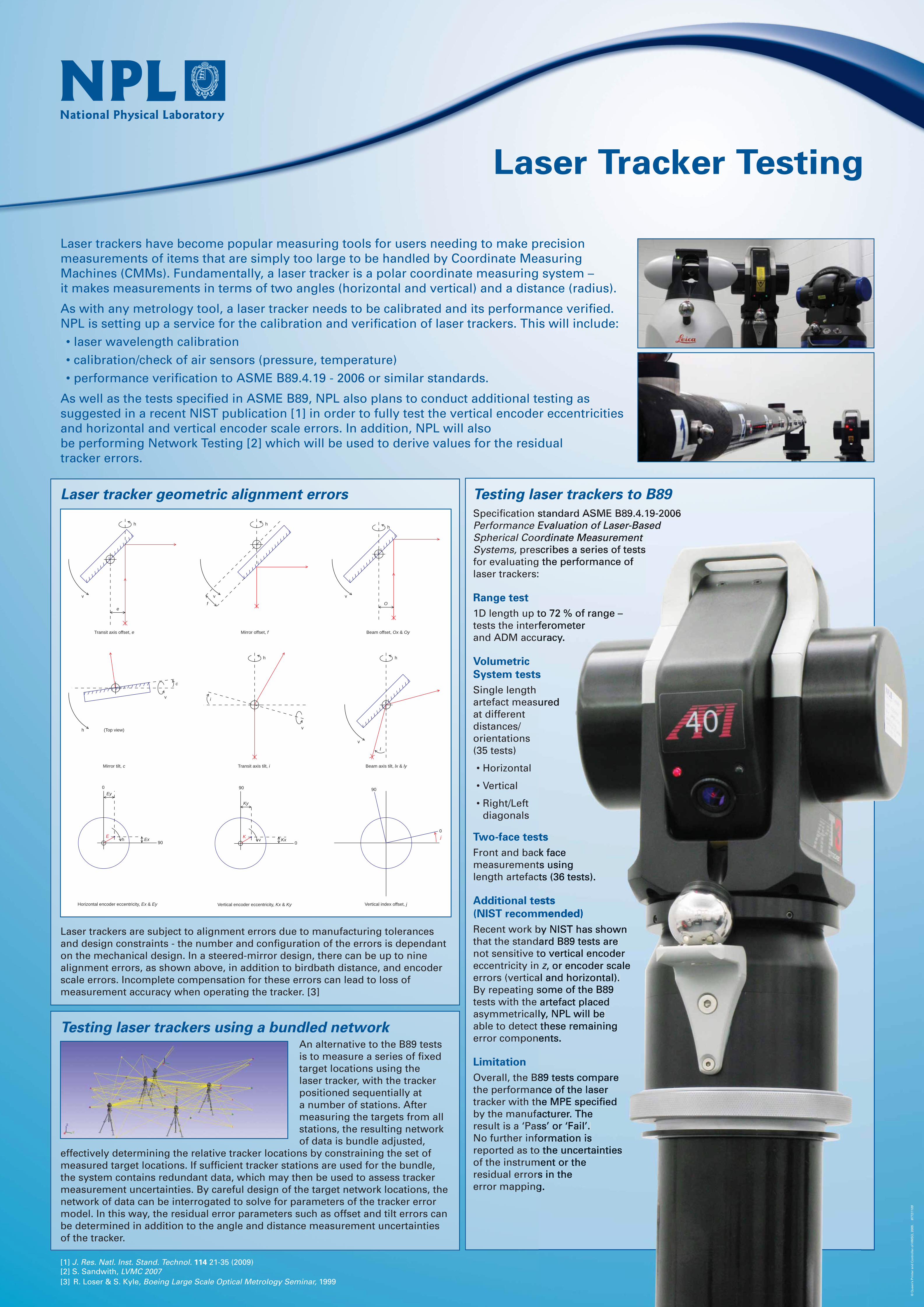
Laser tracker geometric alignment errors
Laser trackers are subject to alignment errors due to manufacturing tolerances and design constraints - the number and confi guration of the errors is dependant on the mechanical design. In a steered-mirror design, there can be up to nine alignment errors, as shown above, in addition to birdbath distance, and encoder scale errors. Incomplete compensation for these errors can lead to loss of measurement accuracy when operating the tracker. [3]
[1] J. Res. Natl. Inst. Stand. Technol. 114 21-35 (2009)[2] S. Sandwith, LVMC 2007[3] R. Loser & S. Kyle, Boeing Large Scale Optical Metrology Seminar, 1999
Testing laser trackers to B89
Specifi cation standard ASME B89.4.19-2006 Performance Evaluation of Laser-Based Spherical Coordinate Measurement Systems, prescribes a series of tests for evaluating the performance of laser trackers:
Range test
1D length up to 72 % of range – tests the interferometer and ADM accuracy.
Volumetric
System tests
Single length artefact measured at different distances/orientations (35 tests)
• Horizontal
• Vertical
• Right/Left diagonals
Two-face tests
Front and back face measurements using length artefacts (36 tests).
Additional tests
(NIST recommended)
Recent work by NIST has shown that the standard B89 tests are not sensitive to vertical encoder eccentricity in z, or encoder scale errors (vertical and horizontal). By repeating some of the B89 tests with the artefact placed asymmetrically, NPL will be able to detect these remaining error components.
Limitation
Overall, the B89 tests compare the performance of the laser tracker with the MPE specifi ed by the manufacturer. The result is a ‘Pass’ or ‘Fail’. No further information is reported as to the uncertainties of the instrument or the residual errors in the error mapping.
Testing laser trackers using a bundled networkAn alternative to the B89 tests is to measure a series of fi xed target locations using the laser tracker, with the tracker positioned sequentially at a number of stations. After measuring the targets from all stations, the resulting network of data is bundle adjusted,
effectively determining the relative tracker locations by constraining the set of measured target locations. If suffi cient tracker stations are used for the bundle, the system contains redundant data, which may then be used to assess tracker measurement uncertainties. By careful design of the target network locations, the network of data can be interrogated to solve for parameters of the tracker error model. In this way, the residual error parameters such as offset and tilt errors can be determined in addition to the angle and distance measurement uncertainties of the tracker.
h
v
e
Transit axis offset, e
h
v
f
Mirror offset, f
h
v
O
Beam offset, Ox & Oy
v
h
Mirror tilt, c
c
(Top view)
h
Transit axis tilt, i
v
i
h
Beam axis tilt, lx & ly
v
l
0
Horizontal encoder eccentricity, Ex & Ey
90h Ex
E
Ey90
Vertical encoder eccentricity, Kx & Ky
0v Kx
K
Ky
Vertical index offset, j
90
0
j
© Q
uee
n’s
Pri
nte
r an
d C
on
tro
ller
of
HM
SO
, 200
9.
877
2/11
09