laser retroreflectance consistent with a polarized single-scatter weak electromagnetic-field...
TRANSCRIPT
Laser retroreflectance consistent with apolarized single-scatter weak electromagnetic-fieldlocalization-interference phenomenon
Walter G. Egan
A set of laser retroreflectance measurements at 0.6328 and 1.159 pum are presented for white and redNextel paints, MgCO3, and Halon for phase angles from 12.10 to 00, with incident radiation perpendicularand parallel to the plane of vision, to determine plane- and cross-polarized components. It is shown thata physical optical retroreflectance can occur for a polarized single-asperity surface scatter or selectedmultiple scattering that preserves the source polarization and coherence. Also subsequent geometricaloptical shadowing of the scattering can occur. At very high resolutions ( 0.1), an optical structureappears on the retroreflectance patterns suggesting a physical optical interference. The observationssupport a theory of retroreflectance based on weak electromagnetic-field localization, and extend theseconcepts with observations of unpolarized scattering. Ideally the dominant, sharp retroreflectance peakis theoretically predicted to be twice the diffuse-background level, and this has been observed for somesamples. At higher angular and spectral resolutions, retroreflectance thus appears to be a combinationof physical and geometrical optical effects.
Key words: Retroreflection, surface scattering, opposition effect, weak localization.
1. Introduction
Retroreflection by a rough surface is the brightnessincrease of a surface as the source-surface-observerangle (also termed the phase angle in astronomy) isdecreased. Peaking is independent of the orienta-tion of the surface relative to the source or observer.Retroreflection (the opposition effect) was first discov-ered by Barabashev,1 who observed a sharp rise in thereflective intensity of lunar maria when the moon isfull. This was further confirmed by Markov,2 vanDiggelen,3 and Gehrels et al. 4
A number of mechanisms have been proposed toexplain theoretically the ubiquitous retroreflectanceeffect occurring not only with natural surfaces,5 6 butalso with photometric standards and coatings. Trow-bridge7 8 has proposed various geometrical optical(ray-tracing) mechanisms, such as lens retroreflec-tion and below-surface-shadowing retroreflection.Hapke9 -12 proposed a theoretical lunar-photometricfunction based on interparticulate shadowing.
When this work was performed, the author was with PolytechnicUniversity, Brooklyn, New York. He is now with York College,City University of New York, Jamaica, New York 11451.
Received 30 October 1991; revised manuscript received 28December 1992.
0003-6935/94/030535-09$06.00/0.o 1994 Optical Society of America.
For electromagnetic waves interacting with a densemedium, the energy scattered back in the retroreflec-tion direction is significantly larger on the averagethan in other directions.13 This enhanced backscat-tering of light propagating in a dense medium hasbeen reported for a dense random distribution oflatex microspheres.14 A sharp peak appears whenthe volume density is above 1%. The peak cannot beexplained by Mie theory, double-passage effects, orradiative-transfer theory: the peak has an angularwidth of between a few tenths of a degree to 2°.A second-order multiple-scattering theory is used tocalculate the scattered field, and Feynman diagramsare used to represent the physical processes. Thetheory yields an angular width of the peak on theorder of the attenuation rate divided by the wavenumber. 15
Further, in solid-state physics, electronic conduc-tion in a disordered material is affected by coherenteffects in their wave function, which is related towave propagation. The probability that an electronwill return to its starting point is not predicted inmodels based on the Boltzman transport equationwhen the mean free path between consecutive colli-sions approaches their wavelength.'3 There is anenhanced probability that an electron will return toits starting point (enhanced backscattering), whichreduces the electrical conductivity (weak electromag-
20 January 1994 / Vol. 33, No. 3 / APPLIED OPTICS 535
netic-field localization).16 This weak localization ofphotons with enhanced backscattering of light hasonly recently been recognized and promises to yieldinsight into the laser-retroreflectance phenomena.
Oetkingl7,18 was the first to demonstrate the opposi-tion effect peaking in laboratory measurements. Hissystem allowed observations to be made to within 1°of the incident direction. All of the materials mea-sured showed the opposition effect. It was pointedout that the opposition effect could not be specularreflectance because it existed even when the surfacewas tilted at angles up to 500 from the incidentdirection.
Subsequently Egan and Hilgeman19-22 used varioustechniques including a cube beam-splitting device tomake retroreflectance measurements at exactly 00incidence and viewing. Surfaces measured were pho-tometric standards and coatings, such as MgCO3,BaSO4 paint, sulfur, and Nextel white, red, blue, andblack paints. The observations of Oetking werecorroborated by their retroreflectance observations,which included lasers. The source collimation in theinitial work of Egan and Hilgeman19 was 10.
The retroreflectance of the photometric samples in0.6328-jim laser illumination varied somewhat fromthat in 0.600-pm incandescent illumination, withblack Nextel paint having a retroreflection ratio (i.e.,retroreflection amplitude ratioed to the reflected am-plitude at the 300 phase angle) of 11 in laser radiation.
In a later set of experiments, Montgomery andKohl23 made opposition-effect measurements with aplane-polarized 0.6328-jim laser on BaSO4 paint,leaves, grass, red clay, sand, and various other sub-stances. Their measurements were of simple-polar-ized and perpendicular-depolarized scattering notrelated to the plane of incidence. They showed thatthe scattered, polarized retroreflectance peak oc-curred only when the analyzer was parallel to thepolarization of the laser. They mentioned that the
RANGE LENGTH f 914 cmLI'
retroreflectance peak in the shadowing mechanismcould result from single-scattering contributions,which should exhibit less depolarization than themultiple diffusely scattered radiation. Equipmentlimitations yielded a lower limit of 10% of the incidentradiation that could be established on the existence ofperpendicularly (i.e., cross-polarized) diffuse backscat-ter at a phase angle of 00.
The present research was similarly directed towardthe measurement of the polarimetric properties ofretroreflection with 100% plane-polarized laser radia-tion at 0.6328-jim and 1.159-im wavelengths downto zero-degree phase angles. The polarized and depo-larized radiation scattered from various surfaces (e.g.,white and red Nextel paint and MgCO3) was sensed.A total of 39 surfaces were sensed, but only theresults from the aforementioned surfaces are pre-sented herein as representative, otherwise the paperwould be excessively long. Various powder surfaceswere also measured, but only Halon (powdered poly-styrene) is discussed in this paper.
2. Experiment
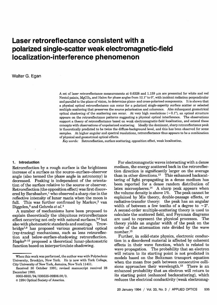
The measurement of retroreflectance requires posi-tioning of the source and sensor so as to allow varyingthe phase angle from approximately 10° to exactly 0°.This positioning required two laser ranges: one (I)for angles from 0.260 to 12.10 (Fig. 1), and another (II)for phase angles from +1.20 to -0.1° (Fig. 2). Thefirst system (Fig. 1) allowed the photomultiplier (RCAtype 6199 for 0.6328-,um and type 7102 for 1.159-,umwavelengths) to be moved laterally in the horizontalplane [the plane of vision (POV)] in the x direction toachieve a range of phase angles. The laser used wasusually the Keuffel & Esser alignment laser (nowCubic Precision Model 71-2610) having a 1.27-cm-diameter beam, with improved collimation (to < 0.5milliradian). However, a Spectra-Physics Model 120laser was used for 1.159-jLm measurements (0.72-mm-
CHOPPER
VERTICALTARGET
LASER I
LASER !APERTURE
PMT APERTUREIILI _
OPAL GLASS450 FRONTSURFACE MIRROR
HOR IZONTALTARGET
Fig. 1. Laser range I: Layout showing laser and adjacent photomultiplier, chopper, baffles, and polarization filter. Targets may beplaced vertically, or for powders, horizontally with the use of the 450 mirror.
536 APPLIED OPTICS / Vol. 33, No. 3 / 20 January 1994
I - - -
beam diameter, 2. 1-milliradian beam divergence).Some measurements were made with the Spectra-Physics Model 120 laser at 0.6328 m (beam diameter0.79 mm, beam divergence 1.0 mrad). Two sizes ofapertures were used in front of the photomultiplier(PMT in the figure) and also in front of the Keuffel &Esser laser to improve the angular resolution of themeasurements.24 25 The photomultiplier aperturewas 1.27 cm for measurements shown in Figs. 3-7and 9, and 0.424 cm for measurements shown in Figs.8 and 10-12.
The angular resolution of the system was deter-mined experimentally with a precision front-surfacemirror located at the vertical (or horizontal) target.The photomultiplier was traversed across the re-flected laser beam to measure the beam width atFWHIM. The position of the photomultiplier in the xdirection was sensed by a potentiometer attached tothe photomultiplier. The potentiometer was turnedby a rack-and-pinion gear system affixed in the xdirection. The potentiometer output was fed to thex position of a Houston Instruments x-y recorder,and the photomultiplier output to they position froma Princeton Applied Research phase-sensitive ampli-fier. The time for a single scan averaged 10 min, andthis permitted improved speckle averaging. Powdersamples were accommodated through the use of a 450front-surface mirror located at the position of thevertical target.
Range length was usually 425 cm, although therange could be increased to 914 cm to increase theangular resolution of the system. The polarizationfilter was located in front of the photomultiplieraperture, with an opal-glass diffuser at the photomul-tiplier face.
Four polarization configurations were measured,
I RANGE LENGTH
and they are identified first by the plane of polariza-tion of the laser, then by the plane of polarization ofthe sensor relative to the plane defined by the laser,the sample, and the sensor (the POV). For example,I I means a configuration in which the plane ofpolarization of the laser was perpendicular to thePOV and the sensed polarization was parallel to thePOV.
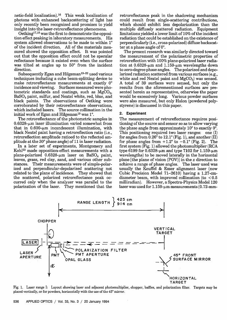
The second laser range (II), shown in Fig. 2, allowsmeasurements at exactly the zero-degree phase angle.Here the photomultiplier (and the rack-and-pinionpotentiometer assembly) are located to permit trans-verse movement of the photomultiplier. The essen-tial difference is a 10-cm-diameter beam splitter; it isan Oriel general-purpose flat-glass component, flat to1 wave over the 2.54-cm diameter and parallel to 30seconds of arc or better. The surface is a standardoptical polish with an Inconel front surface to provideincreased reflection; the rear surface is coated withmagnesium fluoride to reduce reflection to 1-2%between 400 and 700 nm. The transmitted wave-front distortion is less than 1/10 wave/2.54 cm.The position of zero degrees was set by autocollima-tion of the laser beam onto itself to the beamsplitter.
Appropriate baffles are included, as are provisionsfor observing powder samples. The absolute ampli-tude accuracy of the polarization measurements is± 1% for measurements shown in Figs. 3, 4, and 6,and ± 10% for measurements shown in Figs. 8-11.
3. Results
Experimental results of the four amplitudes of thepolarized intensities are shown in Figs. 3, 4, and6-12. Figures 3, 4, 6, and 7 show measurements atangles in the POV between 0.26 and 12.10 on whiteNextel paint, MgCO3, Halon, and red Nextel paint,
} 425cm914 cm l
CHOPPER
_LA_ S I
LASERSER -
APE RTURE
10cm BEAM SPLITTER
POLARIZATION FILTERPMT APERTURE
OPAL GLASS
VERTICALTAR GE T
450 FRONT'NV~ SURFACE MIRROR
I
'--HORIZONTALTARGET
Fig.2. Laser range II: Layout showing laser and perpendicular photomultiplier viewing the 10-cm-diameter beamsplitter. Appropriatebaffles are provided. Targets may be placed vertically, or for powders, horizontally with the use of the 45° mirror.
20 January 1994 / Vol. 33, No. 3 / APPLIED OPTICS 537
i%
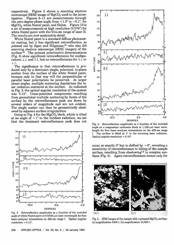
respectively. Figure 5 shows a scanning electronmicroscope (SEM) image of MgCO3 used in the inves-tigation. Figures 8-11 are measurements throughthe zero-degree phase angle from + 1.20 to -0.1°, forMgCO3, white Nextel paint, and Halon. Figure 12 isa set of measurements at high resolution (0.076°) forwhite Nextel paint with the 914-cm range of laser II.The results are now analyzed in detail.
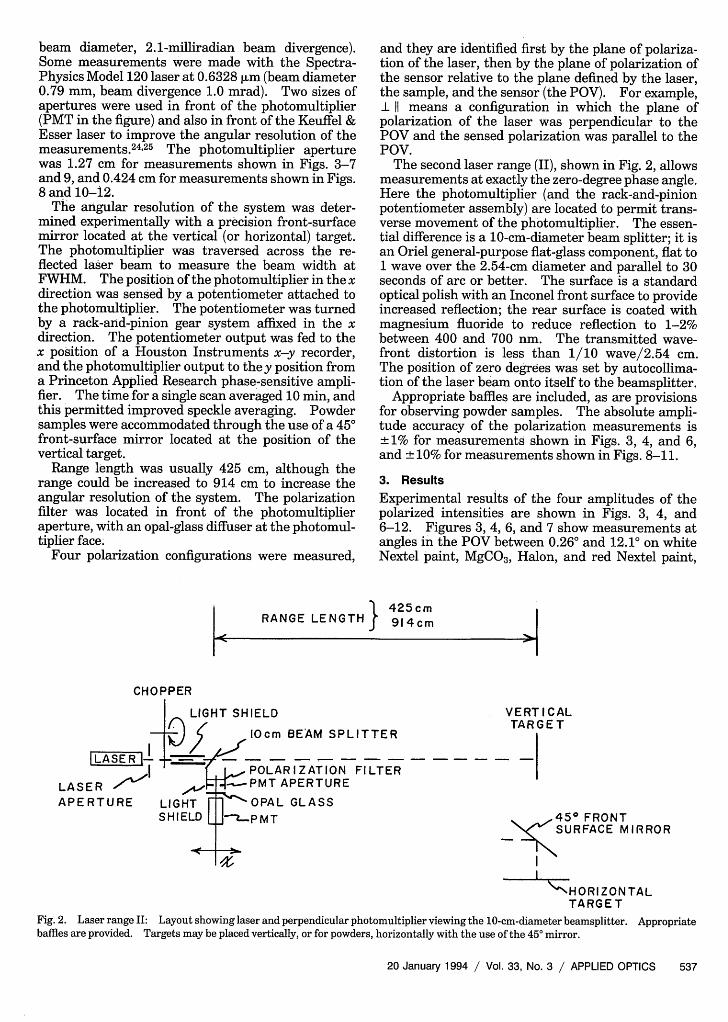
White Nextel paint is a standard diffuse photomet-ric coating, but it has significant retroreflection, aspointed out by Egan and Hilgeman,2 0 who also didscanning electron microscope (SEM) imagery of thesurface.20 The present polarimetric determinations(Fig. 3) show significant retroreflectance for configu-raitons l l and liii, but no retroreflectance for 11 or111.
The significance is that retroreflectance is pro-duced only by a dominant single, polarized, in-planescatter from the surface of the white Nextel paint,because only in that way will the perpendicular orparallel laser polarization be preserved. At largerphase angles, multiple scattering depolarizes the la-ser radiation scattered at the surface. As indicatedin Fig. 3, the optical angular resolution of the systemwas 0.140. Cross-polarized components resultingfrom geometrical multiple scattering by facets of thesurface by the retroreflectance peak are down byseveral orders of magnitude and are not evident.The single scatter can then be geometrically shad-owed by adjacent surface irregularities.
Going to Fig. 4 for the MgCO3 block, which is tiltedat an angle of 10 to the incident radiation, we seethat the dominant retroreflectance peak does not
121
10
8 -W 0-0
D 14-t
2 12
10-
8-
9-8-
I , , , , , , . . I
10.0 5.0 0.0
DEGREES
Fig. 3. Retroreflection amplitudes as a function of the includedangle of white Nextel paint at 0.6328-plm laser wavelength for fourlaser-analyzer orientations on 425-cm range I. Optical angularresolution = 0.14°.
wIn
-J0Q
16-
14-
12-
10-
8-
8-
1607
16-
14-
12-
10-
8-0-
8-
11
I T J
1- I I I I I I I I I I
7~~
I , | I I I I I k
I
I II
I I I '''I'''* II I , , I I , I
10.0 5.0 0.0DEGREES
Fig. 4. Retroreflection amplitudes as a function of the includedangle on a magnesium carbonate block at 1.159-[Lm laser wave-length for four laser-analyzer orientations on the 425-cm rangeI. The surface is tilted at 1 to the incoming laser radiation.Optical angular resolution = 0.18°.
occur at exactly 00 but is shifted by 20, revealing asensitivity of retroreflectance to tilting of the sample
_1 surface, resulting from shadowing7'8 in complex sur-faces (Fig. 5). Again retroreflectance occurs only for
Fig. 5. SEM images of the sample with a pressed MgCO3 surface:(a) magnification 1000x; (b) magnification 10,000x.
538 APPLIED OPTICS / Vol. 33, No. 3 / 20 January 1994
-. 11 I I I I
11
z
I .
.' I ' ' I ' I I I
. . . . | X
1.
la * X l | |
:.
iof6,_
-
I
-it.
the I I and 11 11 orientations, but not for the 11 I or I 11orientations. The MgCO3 surface (Fig. 5) is a ran-dom, apparently on-end platelet structure as shownby the SEM imagery2627 (sometimes termed fairycastle); it is not amenable to systematic structurecharacterizations. It is difficult to conceive of thegeometrical optical-lens mechanism of Trowbridge7
as an explanation of the observed retroreflectances.The present measurements (Fig. 4) were made at1.159-pm wavelength with an optical angular resolu-tion of 0. 180.
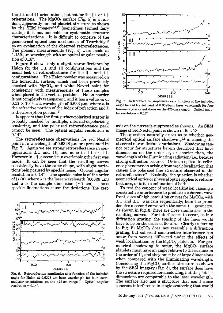
Figure 6 shows only a slight retroreflectance byHalon for the I I and 1111 configurations and theusual lack of retroreflectance for the I I and I 11configurations. The Halon powder was measured onthe horizontal surface, which had been previouslychecked with MgCO3 and white Nextel paint forconsistency with measurements of these sampleswhen placed in the vertical position. Halon powderis not completely transparent, and it has a value nk of0.11 X 10-3 at a wavelength of 0.633 jim, where n isthe refractive portion of the index of refraction and kis the absorption portion.27
It appears that the first surface-polarized scatter isprobably masked by multiple, internal-depolarizingscattering, and the polarized retroreflectance peakcannot be seen. The optical angular resolution is0.140.
The retroreflectance observations for red Nextelpaint at a wavelength of 0.6328 jim are presented inFig. 7. Again we see strong retroreflectance in con-figurations II and 11 11, and none in Ill or I 11.However in 11 11, a second run overlapping the first wasmade. It can be seen that the resulting curvesconsistently have the same shape, with slight varia-tions being caused by speckle noise. Optical angularresolution is 0.140. The speckle noise is of the orderof (X/a), where is the laser wavelength (0.6328 jim)and a is the sample dimension (- 1 cm). Thesespeckle fluctuations cause the deviations (the zero
II-
w0
EI--Ja-
1019
o'Sj
I I I I , I I I I
II,111
II I , I I I . .
10_9-
ol I II I I I . .90
10.0 5.0 0.0DEGREES
Fig. 6. Retroreflection amplitudes as a function of the includedangle for Halon at 0.6328-pum laser wavelength for four laser-analyzer orientations on the 425-cm range I. Optical angularresolution = 0.14°.
In
8-
waM-
-J02
6-0-
10-5-0-10-
8-
6-0-6-5-O -
11
11 I I I I I I I .
; e
11 II I I I
Ii I II
rf
r
J-zII 11 ' ' ' I I I ' I I
r_ . , . We . a , | | fr0.0 5.0 0.0
DEGREESFig. 7. Retroreflection amplitudes as a function of the includedangle for red Nextel paint at 0.6328-pLm laser wavelength for fourlaser-analyzer orientations on the 425-cm range I. Optical angu-lar resolution = 0.14°.
axis on the curves is suppressed as shown). An SEMimage of red Nextel paint is shown in Ref. 18.
The question naturally arises as to whether geo-metrical optical surface shadowing78 is causing theobserved retroreflectance variations. Shadowing can-not occur for structures herein described that havedimensions on the order of, or shorter than, thewavelength of the illuminating radiation (i.e., becausestrong diffraction occurs). Or is an optical-interfer-ence phenomenon arising from weak localization thatcauses the polarized fine structure observed in theretroreflectance? Basically, the question is whethergeometrical optics or physical optics applies to retrore-flectance, or is it a combination of both.
To test the concept of weak localization causing aconstructive interference to produce a coherent wavefront, a set of high resolution curves for MgCO3, with
lI and II' was run sequentially; here the primedenotes a second curve with the same I geometry.As shown in Fig. 8, there are close similarities in theresulting curves. For interference to occur, as in adiffraction grating, the spacing of the lines wouldhave to be on the order of 50 jim. Clearly (referringto Fig. 5) MgCO3 does not resemble a diffractiongrating, but coherent constructive interference canoccur from weaves diffracted under the effects ofweak localizataion by the MgCO3 platelets. For geo-metrical shadowing to occur, the MgCO3 surfaceplatelets must have an angle relative to the surface onthe order of 1, and they must be of large dimensionswhen compared with the illuminating wavelength.Considering the MgCO3 surface structure as shownby the SEM imagery (Fig. 5), the surface does havethe structure required for shadowing, but the plateletdimensions are comparable to the laser wavelength.The surface also has a structure that could causecoherent interference in single scattering that would
20 January 1994 / Vol. 33, No. 3 / APPLIED OPTICS 539
. --- or W | E a . . . .
, . . . . . .. . . .
II
I
8- 4-2
6 0
-4
2 . .01.5 1.0 0.5 0.0 -0.5
0 __ _ _ _ _ _ _ _ _ _ _ _ DEGREES
1.5 1.0 0.5 0.0 -0.5DEGREES
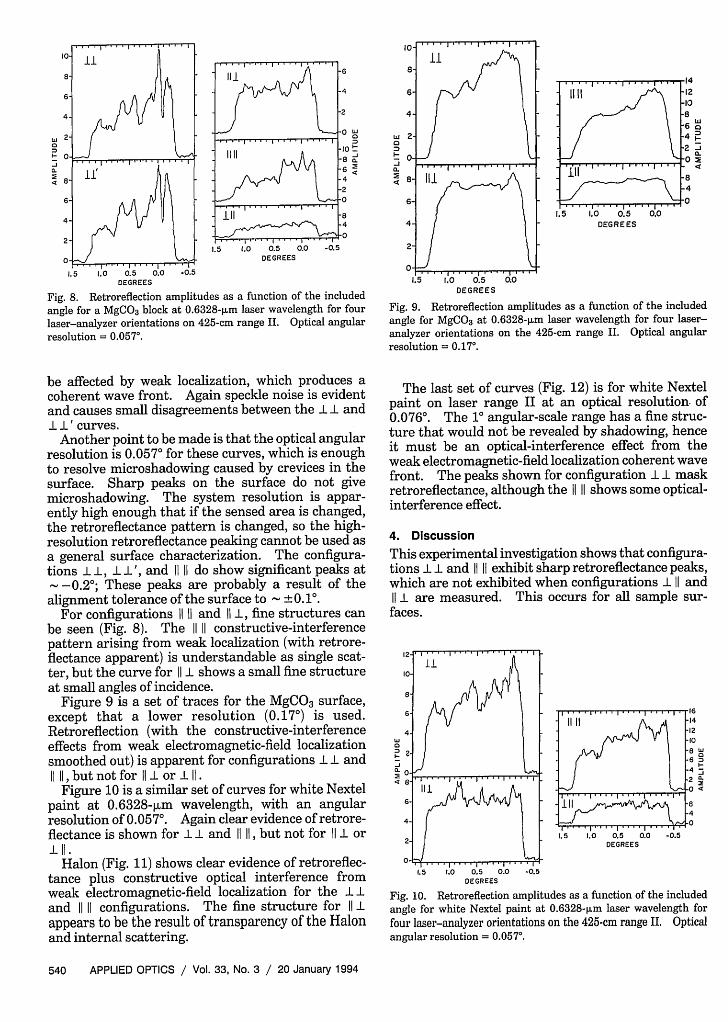
Fig. 8. Retroreflection amplitudes as a function of the includedangle for a MgCO3 block at 0.6328-pm laser wavelength for four
laser-analyzer orientations on 425-cm range II. Optical angularresolution = 0.057°.
be affected by weak localization, which produces acoherent wave front. Again speckle noise is evidentand causes small disagreements between the I I andI ' curves.Another point to be made is that the optical angular
resolution is 0.057° for these curves, which is enoughto resolve microshadowing caused by crevices in thesurface. Sharp peaks on the surface do not givemicroshadowing. The system resolution is appar-ently high enough that if the sensed area is changed,the retroreflectance pattern is changed, so the high-resolution retroreflectance peaking cannot be used asa general surface characterization. The configura-tions II, II', and 11 11 do show significant peaks at-0.20; These peaks are probably a result of thealignment tolerance of the surface to 0.10.
For configurations 11 11 and 11 I, fine structures canbe seen (Fig. 8). The 1111 constructive-interferencepattern arising from weak localization (with retrore-flectance apparent) is understandable as single scat-ter, but the curve for I I shows a small fine structureat small angles of incidence.
Figure 9 is a set of traces for the MgCO3 surface,except that a lower resolution (0.17°) is used.Retroreflection (with the constructive-interferenceeffects from weak electromagnetic-field localizationsmoothed out) is apparent for configurations I I andI I, but not for 11 Il or I 11.
Figure 10 is a similar set of curves for white Nextelpaint at 0.6328-jim wavelength, with an angularresolution of 0.057°. Again clear evidence of retrore-flectance is shown for I I and 11 11, but not for II l or1LI.
Halon (Fig. 11) shows clear evidence of retroreflec-tance plus constructive optical interference fromweak electromagnetic-field localization for the Iland 11 11 configurations. The fine structure for 11 lappears to be the result of transparency of the Halonand internal scattering.
w
I--J
a.M
111 m \
...I . ., .I .a
1.5 I- I I I . . . l 1.0 0.5
DEGREES
.0 .0.0
-12-108
-6 WC.4 '
-4'-02
-8-4-0
DEGREES
Fig. 9. Retroreflection amplitudes as a function of the includedangle for MgCO3 at 0.6328-pum laser wavelength for four laser-analyzer orientations on the 425-cm range II. Optical angularresolution = 0.17°.
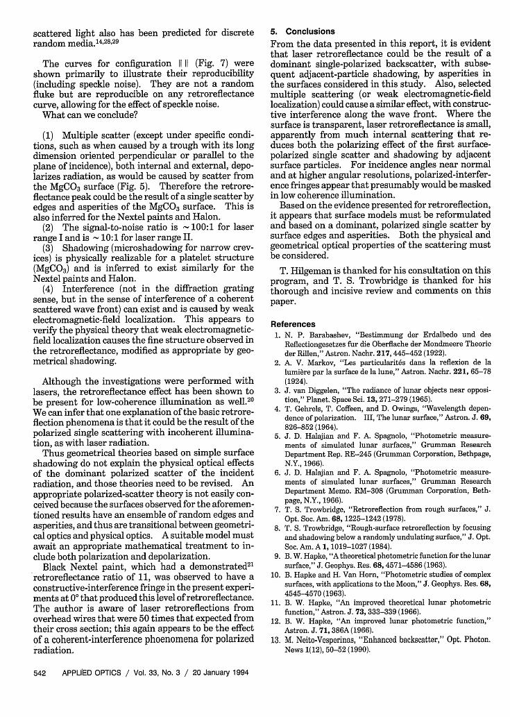
The last set of curves (Fig. 12) is for white Nextelpaint on laser range II at an optical resolution. of0.0760. The 10 angular-scale range has a fine struc-ture that would not be revealed by shadowing, henceit must be an optical-interference effect from theweak electromagnetic-field localization coherent wavefront. The peaks shown for configuration I I maskretroreflectance, although the l1 ii shows some optical-interference effect.
4. DiscussionThis experimental investigation shows that configura-tions I and 11 i1 exhibit sharp retroreflectance peaks,which are not exhibited when configurations I and11 I are measured. This occurs for all sample sur-
faces.
0
0.4
...............1.5 1.0 0.5 0.0DEGREES
-0.5
4
0
-J.12
1.5 .0 0.5 0.0 -0.5DEGREES
Fig. 10. Retroreflection amplitudes as a function of the includedangle for white Nextel paint at 0.6328-pLm laser wavelength forfour laser-analyzer orientations on the 425-cm range II. Opticalangular resolution = 0.057°.
540 APPLIED OPTICS / Vol. 33, No. 3 / 20 January 1994
I
. .... .... .... .,| ..., ... .. .. |....,.. .I1 1I 1e
I,,c
.8
.6-4.2
0ill .~~~~~84
. . . . .. . . . . . . . . . 0
T. I ..|§ ........x lI
Li ' i .e
0 -
V~~~~~~~. 1.1.-00-.
-Ja. 4
4 - 2
.I
14- Il1612- 1210 -88- 4
2- DEGREES
1.5 1.0 0.5 0.0 -0.5DEGREES
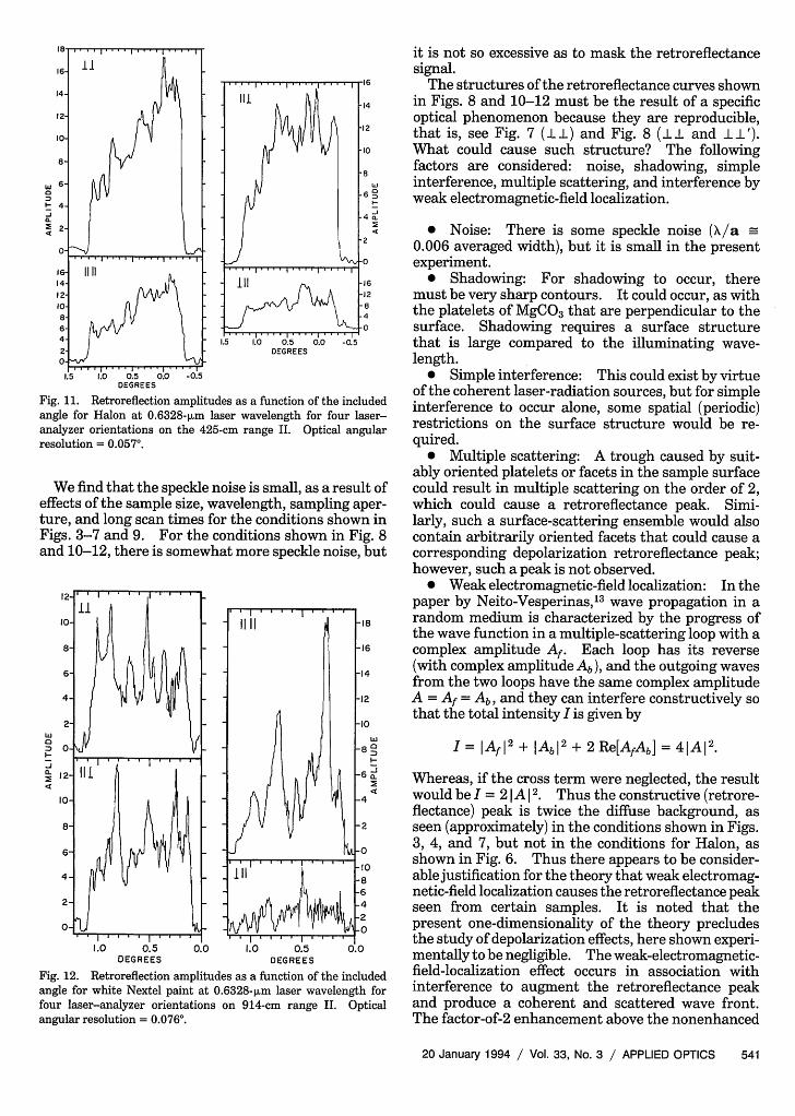
Fig. 11. Retroreflection amplitudes as a function of the includedangle for Halon at 0.6328-pum laser wavelength for four laser-analyzer orientations on the 425-cm range II. Optical angularresolution = 0.057°.
We find that the speckle noise is small, as a result ofeffects of the sample size, wavelength, sampling aper-ture, and long scan times for the conditions shown inFigs. 3-7 and 9. For the conditions shown in Fig. 8and 10-12, there is somewhat more speckle noise, but
Li
I-
I I s
a
0-.J,.
1.0 0.5 0.0 1.0 0.5 0.0DEGREES DEGREES
Fig. 12. Retroreflection amplitudes as a function of the includedangle for white Nextel paint at 0.6328-pum laser wavelength forfour laser-analyzer orientations on 914-cm range II. Opticalangular resolution = 0.076°.
it is not so excessive as to mask the retroreflectancesignal.
The structures of the retroreflectance curves shownin Figs. 8 and 10-12 must be the result of a specificoptical phenomenon because they are reproducible,that is, see Fig. 7 (I) and Fig. 8 (I and II').What could cause such structure? The followingfactors are considered: noise, shadowing, simpleinterference, multiple scattering, and interference byweak electromagnetic-field localization.
* Noise: There is some speckle noise (/a0.006 averaged width), but it is small in the presentexperiment.
* Shadowing: For shadowing to occur, theremust be very sharp contours. It could occur, as withthe platelets of MgCO3 that are perpendicular to thesurface. Shadowing requires a surface structurethat is large compared to the illuminating wave-length.
* Simple interference: This could exist by virtueof the coherent laser-radiation sources, but for simpleinterference to occur alone, some spatial (periodic)restrictions on the surface structure would be re-quired.
* Multiple scattering: A trough caused by suit-ably oriented platelets or facets in the sample surfacecould result in multiple scattering on the order of 2,which could cause a retroreflectance peak. Simi-larly, such a surface-scattering ensemble would alsocontain arbitrarily oriented facets that could cause acorresponding depolarization retroreflectance peak;however, such a peak is not observed.
* Weak electromagnetic-field localization: In thepaper by Neito-Vesperinas,13 wave propagation in arandom medium is characterized by the progress ofthe wave function in a multiple-scattering loop with acomplex amplitude Af. Each loop has its reverse(with complex amplitude Ab), and the outgoing wavesfrom the two loops have the same complex amplitudeA = Af = Ab, and they can interfere constructively sothat the total intensity I is given by
I = AfI2 + Abl2 + 2 Re[AfAb] = 41A12.
Whereas, if the cross term were neglected, the resultwould be I = 21 A 12. Thus the constructive (retrore-flectance) peak is twice the diffuse background, asseen (approximately) in the conditions shown in Figs.3, 4, and 7, but not in the conditions for Halon, asshown in Fig. 6. Thus there appears to be consider-able justification for the theory that weak electromag-netic-field localization causes the retroreflectance peakseen from certain samples. It is noted that thepresent one-dimensionality of the theory precludesthe study of depolarization effects, here shown experi-mentally to be negligible. The weak-electromagnetic-field-localization effect occurs in association withinterference to augment the retroreflectance peakand produce a coherent and scattered wave front.The factor-of-2 enhancement above the nonenhanced
20 January 1994 / Vol. 33, No. 3 / APPLIED OPTICS 541
scattered light also has been predicted for discreterandom media.1 4 ,2 8 29
The curves for configuration 1111 (Fig. 7) wereshown primarily to illustrate their reproducibility(including speckle noise). They are not a randomfluke but are reproducible on any retroreflectancecurve, allowing for the effect of speckle noise.
What can we conclude?
(1) Multiple scatter (except under specific condi-tions, such as when caused by a trough with its longdimension oriented perpendicular or parallel to theplane of incidence), both internal and external, depo-larizes radiation, as would be caused by scatter fromthe MgCO3 surface (Fig. 5). Therefore the retrore-flectance peak could be the result of a single scatter byedges and asperities of the MgCO3 surface. This isalso inferred for the Nextel paints and Halon.
(2) The signal-to-noise ratio is - 100:1 for laserrange I and is - 10:1 for laser range II.
(3) Shadowing (microshadowing for narrow crev-ices) is physically realizable for a platelet structure(MgCO3) and is inferred to exist similarly for theNextel paints and Halon.
(4) Interference (not in the diffraction gratingsense, but in the sense of interference of a coherentscattered wave front) can exist and is caused by weakelectromagnetic-field localization. This appears toverify the physical theory that weak electromagnetic-field localization causes the fine structure observed inthe retroreflectance, modified as appropriate by geo-metrical shadowing.
Although the investigations were performed withlasers, the retroreflectance effect has been shown tobe present for low-coherence illumination as well.20
We can infer that one explanation of the basic retrore-flection phenomena is that it could be the result of thepolarized single scattering with incoherent illumina-tion, as with laser radiation.
Thus geometrical theories based on simple surfaceshadowing do not explain the physical optical effectsof the dominant polarized scatter of the incidentradiation, and those theories need to be revised. Anappropriate polarized-scatter theory is not easily con-ceived because the surfaces observed for the aforemen-tioned results have an ensemble of random edges andasperities, and thus are transitional between geometri-cal optics and physical optics. A suitable model mustawait an appropriate mathematical treatment to in-clude both polarization and depolarization.
Black Nextel paint, which had a demonstrated 2lretroreflectance ratio of 11, was observed to have aconstructive-interference fringe in the present experi-ments at 00 that produced this level of retroreflectance.The author is aware of laser retroreflections fromoverhead wires that were 50 times that expected fromtheir cross section; this again appears to be the effectof a coherent-interference phoenomena for polarizedradiation.
5. Conclusions
From the data presented in this report, it is evidentthat laser retroreflectance could be the result of adominant single-polarized backscatter, with subse-quent adjacent-particle shadowing, by asperities inthe surfaces considered in this study. Also, selectedmultiple scattering (or weak electromagnetic-fieldlocalization) could cause a similar effect, with construc-tive interference along the wave front. Where thesurface is transparent, laser retroreflectance is small,apparently from much internal scattering that re-duces both the polarizing effect of the first surface-polarized single scatter and shadowing by adjacentsurface particles. For incidence angles near normaland at higher angular resolutions, polarized-interfer-ence fringes appear that presumably would be maskedin low coherence illumination.
Based on the evidence presented for retroreflection,it appears that surface models must be reformulatedand based on a dominant, polarized single scatter bysurface edges and asperities. Both the physical andgeometrical optical properties of the scattering mustbe considered.
T. Hilgeman is thanked for his consultation on thisprogram, and T. S. Trowbridge is thanked for histhorough and incisive review and comments on thispaper.
References1. N. P. Barabashev, "Bestimmung der Erdalbedo und des
Reflectiongesetzes fur die Oberflache der Mondmeere Theorieder Rillen," Astron. Nachr. 217, 445-452 (1922).
2. A. V. Markov, "Les particularit6s dans la reflexion de lalumiere par la surface de la lune," Astron. Nachr. 221, 65-78(1924).
3. J. van Diggelen, "The radiance of lunar objects near opposi-tion," Planet. Space Sci. 13, 271-279 (1965).
4. T. Gehrels, T. Coffeen, and D. Owings, "Wavelength depen-dence of polarization. III, The lunar surface," Astron. J. 69,826-852 (1964).
5. J. D. Halajian and F. A. Spagnolo, "Photometric measure-ments of simulated lunar surfaces," Grumman ResearchDepartment Rep. RE-245 (Grumman Corporation, Bethpage,N.Y., 1966).
6. J. D. Halajian and F. A. Spagnolo, "Photometric measure-ments of simulated lunar surfaces," Grumman ResearchDepartment Memo. RM-308 (Grumman Corporation, Beth-page, N.Y., 1966).
7. T. S. Trowbridge, "Retroreflection from rough surfaces," J.Opt. Soc. Am. 68, 1225-1242 (1978).
8. T. S. Trowbridge, "Rough-surface retroreflection by focusingand shadowing below a randomly undulating surface," J. Opt.Soc. Am. A 1, 1019-1027 (1984).
9. B. W. Hapke, "A theoretical photometric function for the lunarsurface," J. Geophys. Res. 68, 4571-4586 (1963).
10. B. Hapke and H. Van Horn, "Photometric studies of complexsurfaces, with applications to the Moon," J. Geophys. Res. 68,4545-4570 (1963).
11. B. W. Hapke, "An improved theoretical lunar photometricfunction," Astron. J. 73, 333-339 (1966).
12. B. W. Hapke, "An improved lunar photometric function,"Astron. J. 71, 386A (1966).
13. M. Neito-Vesperinas, "Enhanced backscatter," Opt. Photon.News 1(12),50-52 (1990).
542 APPLIED OPTICS / Vol. 33, No. 3 / 20 January 1994